data sheet - 2D Debus & Diebold MeÃsysteme GmbH
data sheet - 2D Debus & Diebold MeÃsysteme GmbH
data sheet - 2D Debus & Diebold MeÃsysteme GmbH
- No tags were found...

You also want an ePaper? Increase the reach of your titles
YUMPU automatically turns print PDFs into web optimized ePapers that Google loves.
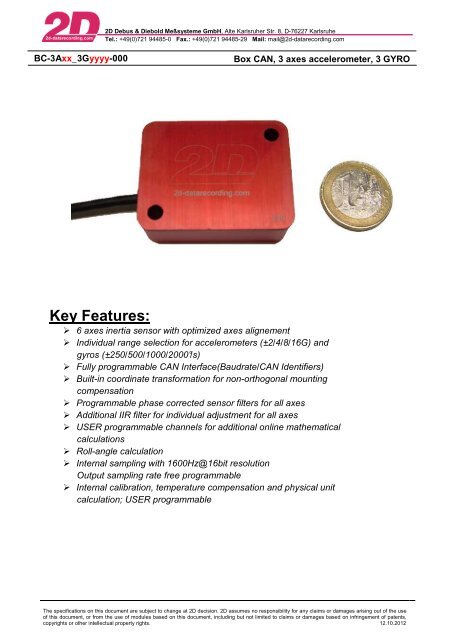
<strong>2D</strong> <strong>Debus</strong> & <strong>Diebold</strong> Meßsysteme <strong>GmbH</strong>, Alte Karlsruher Str. 8, D-76227 KarlsruheTel.: +49(0)721 94485-0 Fax.: +49(0)721 94485-29 Mail: mail@2d-<strong>data</strong>recording.comBC-3Axx_3Gyyyy-000Box CAN, 3 axes accelerometer, 3 GYROKey Features: 6 axes inertia sensor with optimized axes alignement Individual range selection for accelerometers (±2/4/8/16G) andgyros (±250/500/1000/2000°/s) Fully programmable CAN Interface(Baudrate/CAN Identifiers) Built-in coordinate transformation for non-orthogonal mountingcompensation Programmable phase corrected sensor filters for all axes Additional IIR filter for individual adjustment for all axes USER programmable channels for additional online mathematicalcalculations Roll-angle calculation Internal sampling with 1600Hz@16bit resolutionOutput sampling rate free programmable Internal calibration, temperature compensation and physical unitcalculation; USER programmableThe specifications on this document are subject to change at <strong>2D</strong> decision. <strong>2D</strong> assumes no responsibility for any claims or damages arising out of the useof this document, or from the use of modules based on this document, including but not limited to claims or damages based on infringement of patents,copyrights or other intellectual property rights. 12.10.2012
<strong>2D</strong> <strong>Debus</strong> & <strong>Diebold</strong> Meßsysteme <strong>GmbH</strong>, Alte Karlsruher Str. 8, D-76227 KarlsruheTel.: +49(0)721 94485-0 Fax.: +49(0)721 94485-29 Mail: mail@2d-<strong>data</strong>recording.comBC-3Axx_3Gyyyy-000Box CAN, 3 axes accelerometer, 3 GYROTechnical SpecificationsSpecification 3 axis accelerationRange switchable with 3 axisError of linearityLowpass filter response(programmable)Specification yaw-rate sensorSensitivityError for linearityLowpass filter response(programmable)CAN OutputCAN IDTransmission rate, programmable by user±2, ±4,±8,±16 G
<strong>2D</strong> <strong>Debus</strong> & <strong>Diebold</strong> Meßsysteme <strong>GmbH</strong>, Alte Karlsruher Str. 8, D-76227 KarlsruheTel.: +49(0)721 94485-0 Fax.: +49(0)721 94485-29 Mail: mail@2d-<strong>data</strong>recording.comBC-3Axx_3Gyyyy-000Box CAN, 3 axes accelerometer, 3 GYRODimensionsCAN identifier allocationCAN ID (default)CAN-ID Byte 0 Byte 1 Byte 2 Byte 3 Byte 4 Byte 5 Byte 6 Byte 7Hi Lo Hi Lo Hi Lo Hi Lo0x498 ACC_X ACC_Y ACC_Z T_ACC0x499 GYRO_X GYRO_Y GYRO_Z T_GYRO0x000* ACC_X_IIR ACC_Y_IIR ACC_Z_IIR T_ACC_IIR0x000* GYRO_X_IIR GYRO_Y_IIR GYRO_Z_IIR T_GYRO_IIR0x000* ACC_X_ROT ACC_Y_ROT ACC_Z_ROT T_ACC_IIR0x000* GYRO_X_IIR GYRO_Y_IIR GYRO_Z_IIR T_GYRO_IIR *optionalFormulas to calculate physical valuesChannel Multiplicator OffsetACC_X [m/s 2 ] = 0,005 * digits - 163,835ACC_Y [m/s 2 ] = 0,005 * digits - 163,835ACC_Z [m/s 2 ] = 0,005 * digits - 163,835Channel Multiplicator OffsetGYRO_X [°/s] = 0,01 * digits - 327,67GYRO_Y [°/s] = 0,01 * digits - 327,67GYRO_Z [°/s] = 0,01 * digits - 327,67Connector LayoutConnector typePin Name Description Color1 CAN H CAN Bus High White2 CAN L CAN Bus Low Green3 GND Ground Black4 n.c. Not Connected -5 Vext Power in (8 – 18V) redmating plugplug @ moduleOn request other options are possible for the CAN-line connector of all <strong>2D</strong> CAN modules.Please take a look at the product group [Connectors] in the <strong>2D</strong> Product catalog.The specifications on this document are subject to change at <strong>2D</strong> decision. <strong>2D</strong> assumes no responsibility for any claims or damages arising out of the useof this document, or from the use of modules based on this document, including but not limited to claims or damages based on infringement of patents,copyrights or other intellectual property rights. 12.10.2012
<strong>2D</strong> <strong>Debus</strong> & <strong>Diebold</strong> Meßsysteme <strong>GmbH</strong>, Alte Karlsruher Str. 8, D-76227 KarlsruheTel.: +49(0)721 94485-0 Fax.: +49(0)721 94485-29 Mail: mail@2d-<strong>data</strong>recording.comBC-3Axx_3Gyyyy-000Box CAN, 3 axes accelerometer, 3 GYROSupplementary SheetThe Figure shown beneath shows the “correct directions” for the accelerometers in three directions (x, y and z) as well asthe three included gyros. The directions are essential if you calibrate this sensor using WinIt.a xa ya z“right-hand rule“ for orientation of axis a x,y,zG x,y,z“right-hand rule“ for gyro sense of rotationsThe specifications on this document are subject to change at <strong>2D</strong> decision. <strong>2D</strong> assumes no responsibility for any claims or damages arising out of the useof this document, or from the use of modules based on this document, including but not limited to claims or damages based on infringement of patents,copyrights or other intellectual property rights. 12.10.2012