I-688 GSE Gas Transmitter Installation, Operation and ... - Brasch
I-688 GSE Gas Transmitter Installation, Operation and ... - Brasch
I-688 GSE Gas Transmitter Installation, Operation and ... - Brasch
- No tags were found...

Create successful ePaper yourself
Turn your PDF publications into a flip-book with our unique Google optimized e-Paper software.
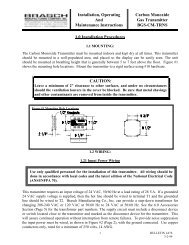
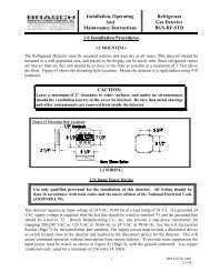
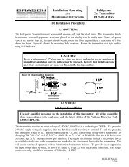
QUICK INSTALLATION GUIDEPlease read this entire manual before attempting to install <strong>and</strong> operate this gastransmitter. But, if you do not read the manual, this Quick <strong>Installation</strong> Guide willprovide the basic steps necessary to install <strong>and</strong> operate the transmitter. In each step,reference is made to the portion of the manual where more complete information canbe obtained.Follow the basic steps listed below to install <strong>and</strong> operate your <strong>Brasch</strong> <strong>Gas</strong> <strong>Transmitter</strong>. However, werecommend that you read the complete manual to obtain a more detailed description of the transmitter’scapabilities.Installing <strong>and</strong> operating your <strong>Brasch</strong> transmitter:Step 1Determine the location for mounting your transmitter(s). The location(s) may be indicated on thearchitectural drawing. Also, the owner or designer of the facility may be consulted. Mounting guidelines canbe found on page 1 of this manual.Step 2WARNINGThis transmitter may require the use of voltage levels high enough to cause fatal injuries.Proper procedures must be followed anytime work is performed on this unit.Only Qualified Personnel Should Attempt To Install, Maintain Or Service ThisEquipment.The transmitter can operate from 24 VAC or +/- 25 VDC. If the transmitter provides a signal to acustomer supplied building management system, or a <strong>Brasch</strong> GDCP-0, GDCP-1, GDCP-2, or GDCP-3control panel, the transmitter is connected to 24VAC. This voltage is provided by a step-downtransformer connected to the building’s AC line.Provide a dedicated circuit, at the required 24 VAC <strong>and</strong> 5 VA, at each transmitter mounting location. Followall national <strong>and</strong> local wiring codes. The wiring should be at least 14 AWG. A conductor, connected to theearth ground, should also be provided. The circuit must include a disconnect switch located within easyreach of the transmitter.To access the power connections, it is not necessary to remove the transmitter’s housing cover. Allconnections to the transmitter are made using the wiring that exits through the conduit fitting on the top ofthe transmitter. See the wiring diagram on page 5 <strong>and</strong> the suggested mounting method on page 13.CAUTIONOperating this transmitter with the incorrect voltage <strong>and</strong> power requirement can causeinternal electrical components to overheat <strong>and</strong> fail. <strong>Operation</strong> under these conditions willvoid the manufacturer’s warranty, <strong>and</strong> the installer will be responsible for any damage thatoccurs.Contact <strong>Brasch</strong> Manufacturing Company before connecting power to the transmitter if youare unsure of the correct power requirement.iv