I-688 GSE Gas Transmitter Installation, Operation and ... - Brasch
I-688 GSE Gas Transmitter Installation, Operation and ... - Brasch
I-688 GSE Gas Transmitter Installation, Operation and ... - Brasch
- No tags were found...

You also want an ePaper? Increase the reach of your titles
YUMPU automatically turns print PDFs into web optimized ePapers that Google loves.
QUICK INSTALLATION GUIDEPlease read this entire manual before attempting to install <strong>and</strong> operate this gastransmitter. But, if you do not read the manual, this Quick <strong>Installation</strong> Guide willprovide the basic steps necessary to install <strong>and</strong> operate the transmitter. In each step,reference is made to the portion of the manual where more complete information canbe obtained.Follow the basic steps listed below to install <strong>and</strong> operate your <strong>Brasch</strong> <strong>Gas</strong> <strong>Transmitter</strong>. However, werecommend that you read the complete manual to obtain a more detailed description of the transmitter’scapabilities.Installing <strong>and</strong> operating your <strong>Brasch</strong> transmitter:Step 1Determine the location for mounting your transmitter(s). The location(s) may be indicated on thearchitectural drawing. Also, the owner or designer of the facility may be consulted. Mounting guidelines canbe found on page 1 of this manual.Step 2WARNINGThis transmitter may require the use of voltage levels high enough to cause fatal injuries.Proper procedures must be followed anytime work is performed on this unit.Only Qualified Personnel Should Attempt To Install, Maintain Or Service ThisEquipment.The transmitter can operate from 24 VAC or +/- 25 VDC. If the transmitter provides a signal to acustomer supplied building management system, or a <strong>Brasch</strong> GDCP-0, GDCP-1, GDCP-2, or GDCP-3control panel, the transmitter is connected to 24VAC. This voltage is provided by a step-downtransformer connected to the building’s AC line.Provide a dedicated circuit, at the required 24 VAC <strong>and</strong> 5 VA, at each transmitter mounting location. Followall national <strong>and</strong> local wiring codes. The wiring should be at least 14 AWG. A conductor, connected to theearth ground, should also be provided. The circuit must include a disconnect switch located within easyreach of the transmitter.To access the power connections, it is not necessary to remove the transmitter’s housing cover. Allconnections to the transmitter are made using the wiring that exits through the conduit fitting on the top ofthe transmitter. See the wiring diagram on page 5 <strong>and</strong> the suggested mounting method on page 13.CAUTIONOperating this transmitter with the incorrect voltage <strong>and</strong> power requirement can causeinternal electrical components to overheat <strong>and</strong> fail. <strong>Operation</strong> under these conditions willvoid the manufacturer’s warranty, <strong>and</strong> the installer will be responsible for any damage thatoccurs.Contact <strong>Brasch</strong> Manufacturing Company before connecting power to the transmitter if youare unsure of the correct power requirement.iv
PART ONE – INSTALLATIONMounting the <strong>Transmitter</strong>The ability of the transmitter to efficiently sense the target gas depends greatly upon proper selection of themounting location. This transmitter monitors the area around it by sampling the air that passes by thesensor. Therefore, the transmitter should be positioned where it can sample air that contains a target gasconcentration representative of the average value in that area.When determining the mounting location, give special consideration to the following guidelines.• Use one transmitter for each 7000 to 9000 square feet of area to be monitored.• The types of gases the transmitter is designed to monitor have densities approximately equal to that ofair. For maximum safety, mount the transmitter at the average breathing height.• Avoid mounting locations that would not be representative of the average gas value in that area.Locations near doorways, fans, ventilation inlets <strong>and</strong> outlets <strong>and</strong> areas with high volume of air flowshould be avoided.• Avoid locations that would allow direct contact with water. Mounting the transmitter near outside garagedoors may allow rain to hit the transmitter when the door is open.• Avoid locations that are directly in the outlet air vents of heaters or air conditioners.• Do not allow exhaust from engines to flow directly on the transmitter. This transmitter is designed tosense gas concentrations that are 300 to 1000 times less concentrated than the gas levels found inengine exhaust. Also, engine exhaust contains high levels of other components. These componentscan shorten the useful life of the sensor if they contact the sensor before being diluted by the room airvolume.• Avoid mounting locations where the transmitter may be hit by passing vehicles. If the transmitter mustbe mounted in these locations, provide a shielding cage around the transmitter for protection.• Do not restrict the air flow to the transmitter housing.• Do not mount the transmitter near containers of chemicals such as gasoline, kerosene, alcohol or othercleaning fluids. High level concentrations of these chemicals may be mistaken as the target gas by thesensor <strong>and</strong> cause false readings. Also, some welding gases may cause false readings.The transmitter is attached in the mounting position in one of three ways.• Attach the housing to conduit using appropriate conduit fittings. If you use this method, make sure thatthe conduit is securely attached to a solid support. Firmly tighten the threaded nuts on the conduitfittings inside the transmitter housing so they will not loosen over time.• Attach the housing to a four inch square conduit box using the ½ inch fitting provided with thetransmitter. Make sure that the conduit box is firmly fastened to the mounting surface with screws.Securely tighten the fitting nut on the inside of the conduit box so it will not loosen over time. Fig. 6, inthe appendix, illustrates how the box is connected to the transmitter.• Attach the housing to a solid support base using screws through the internal housing mounting holes.This method requires removal of the housing cover to gain access to the mounting holes. A mountinghole is located at the top <strong>and</strong> bottom of each of the housing end walls.Find a flat area at least 6” high by 6” wide <strong>and</strong> place the back of the open housing flat against it. Usinga pencil, or other slender marking tool, mark the location of the four mounting holes using the housingas a template. Start the screws without the housing in place to avoid any possibility of damage to thehousing or circuit board. Remove the screws, place the housing in position <strong>and</strong> install the mountingscrews. Do not over-tighten the screws <strong>and</strong> crack the plastic housing. Being careful not to damage theprinted circuit board, replace the housing cover <strong>and</strong> securely tighten the four cover retaining screws.1
.PART TWO – TECHNICAL SPECIFICATIONSDescriptionThe <strong>Brasch</strong> <strong>Gas</strong> <strong>Transmitter</strong> is designed to function as a gas sensor <strong>and</strong> signal transmitter. The transmitterconsists of a sensor <strong>and</strong> digital control circuitry. A 4-20 ma. analog output circuit is available to providesignals to a customer supplied building management controller. A microprocessor monitors the signal fromthe sensor circuitry, converts that signal to a digital value <strong>and</strong>, on dem<strong>and</strong>, transfers the digital signal to a<strong>Brasch</strong> <strong>GSE</strong> Detector. In the case of the 4-20 ma. circuit, the digital signal is converted to a current <strong>and</strong>sent over a two wire current loop to the building management controller.The sensor used in the transmitter operates on the electrochemical principle. A current is produced whenthe target gas reacts chemically with water inside the sensor. This small current is changed to a voltage bythe transmitter’s circuitry, amplified <strong>and</strong> changed to a digital signal by the microprocessor. This digital signalis proportional to the gas concentration present at the sensor. When requested by the <strong>Brasch</strong> <strong>GSE</strong>Detector, the digital signal is sent to the controller. The transmitter then updates the sensor reading <strong>and</strong>stores it for the next request.The transmitter’s circuitry consists of a printed circuit board mounted inside a polycarbonate housing. Thehousing has a NEMA 1 rating. A port is provided at the top of the housing cover that allows the sensoraccess to the ambient air.Product SpecificationsPower:+/- 25 VDC Input Voltage0.2 Amps24 VAC Input Voltage50/60 Hz.0.200 Amps<strong>Installation</strong> Category:II (local level, over-voltage transients less than 500 volts)Operating Temperature:Storage-50° C to 120° C (-58° F to 248° F)Operating-15° C to 40° C (5° F to 104° F)Humidity:10% to 90% (non-condensing)Front Panel Indicators:Power (green LED)`Dimensions: 4.8” W x 4.72” H x 2.16” D (12.2 cm W x 12 cm H x 5.5 cm D)Weight:Housing:1 lb. ( 0.5 Kg.)Gray, NEMA 1, polycarbonate plasticAgency Acceptance: ETL listed to UL 3111-12
Target <strong>Gas</strong> SpecificationsThe <strong>Brasch</strong> <strong>Gas</strong> <strong>Transmitter</strong> is available for monitoring several different target gases. Various regulatoryagencies have determined the threshold concentrations at which these gases become dangerous. <strong>Brasch</strong>Manufacturing Company has designed their transmitters so that the measurement ranges for each targetgas meet the agencies’ requirements.Each target gas, for which <strong>Brasch</strong> currently produces a transmitter, is listed below along with the relevantconcentration specifications.Carbon MonoxideFull Scale Span:Resolution:200 PPM1 PPMNitrogen DioxideFull Scale Span: 10.0 PPM, (BMS); 2.0 PPM, (GDCP-0, 1, 2, 3)Resolution:0.05 PPMOxygenFull Scale Span: 25.0 %Resolution: 0.1 %Description of Front Panel IndicatorsThe only indicator on the transmitter’s front panel is the green power lamp. This lamp glows continuouswhenever power is present.How the <strong>Transmitter</strong> Senses the Target <strong>Gas</strong>Ambient air surrounding the transmitter contacts the sensor through the sensing port at the top of thehousing cover. Any target gas present in this air causes a response from the sensor. If the transmitter islocated properly, the sensor will respond to the average amount of the target gas present in the area. Forhelp in properly locating the transmitter, please read the mounting guidelines on page 1.The transmitter monitors the actual concentration of the target gas exposed to the sensor. This actual valuemay be different than the time-weighted-average values displayed by most of the personal gas monitors.Please take this difference into account when comparing the response of the two units.Obtaining the Best <strong>Operation</strong>Carbon Monoxide <strong>and</strong>/or Nitrogen Dioxide <strong>Transmitter</strong>sThese transmitters are placed in areas to monitor for a rising concentration of the target gas.No two installations will be exactly the same. The number of gas producing sources, air flow patterns insidethe room, the total room volume <strong>and</strong> the exact location of the transmitter(s) influence how effective each is insensing the target gas concentration.3
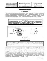
In some cases, you may find that a target gas source is too close to the transmitter. Consider othermounting locations for the transmitter, or move the gas source farther away.Oxygen DetectorThis transmitter is placed in areas to monitor for a decreasing concentration of oxygen. Usually a controllerwill respond by activating a ventilation system to bring fresh air, at a normal oxygen concentration, into thearea being monitored. In other instances, the controller may only be used to sound an alarm allowingworkers to evacuate the area.The number of oxygen depleting sources, air flow patterns in the area, the total room volume <strong>and</strong> thetransmitter location influence the effectiveness of the transmitter.Under most conditions, the only variable that the installer can change will be the location of the transmitter.Please see page 1 for mounting guidelines.Assembly View <strong>and</strong> Wiring DiagramsThe following assembly view <strong>and</strong> wiring diagrams should be referenced during installation.Fig. 1: Assembly View: Sensor P.C. Board to <strong>Transmitter</strong> Cover4
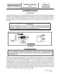
Fig. 2: Wiring Diagram, Others BMS to Remote <strong>Transmitter</strong>5
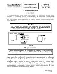
Fig. 3: Wiring Diagram, <strong>Brasch</strong> <strong>GSE</strong> Detector to Remote <strong>Transmitter</strong>6
PART THREE – TROUBLESHOOTING <strong>and</strong> MAINTENANCETesting the Response to the Target <strong>Gas</strong>Carbon Monoxide or Nitrogen Dioxide <strong>Transmitter</strong>sTesting these transmitters require that the target gas be applied to the sensor using one of two methods.<strong>Gas</strong> can be applied from a tank of air containing a known concentration of the target gas, or a level of targetgas sufficient to activate the control system can be produced from the exhaust of an operating engine. Usea gasoline engine to produce CO <strong>and</strong> a diesel engine to produce nitrogen dioxide.Of the two methods of obtaining test gas, the simplest is operating an engine in the vicinity of the transmitterunder test. The engine should be placed about 10 feet away from the transmitter so that exhaust gases willnot contact the transmitter directly.CautionAllowing the transmitter to come in direct contact with undiluted exhaust gases will decreasethe expected useful lifetime of the sensor. The high concentration of acids <strong>and</strong> othercomponents in the exhaust gas will overload the activated carbon filter inside the sensor <strong>and</strong>will increase the effects of interfering gases upon the accuracy of the sensor.If the sensor becomes damaged, it must be replaced with a new sensor calibrated at thefactory.The engine should be allowed to operate until the level of the target gas is sufficient to activate theventilation system. Depending upon the volume of the area where the transmitter is located, this may takefrom 10 to 30 minutes.Using test gas applied from a tank has the advantage of speed as well as assurance that the transmitter isresponding to the target gas. However, the gas must be applied directly to the sensor if the response is tobe close to the value present in the tank. The test gas can not be allowed to become diluted by the air in theroom before it comes in contact with the sensor. This reduces the concentration to a level too low to givethe desired result.While a test gas mixture is readily available for CO, gas mixtures containing low PPM levels of nitrogendioxide is not available.When testing the CO sensor response using test gas from a tank, the gas is allowed to flow through aflexible hose into a plastic fitting that is placed directly over the sensing port. Allow 2 to 3 minutes for thesensor to respond to the test gas. If the test gas has the required concentration of CO, the controller shouldrespond by displaying a concentration <strong>and</strong> activating the appropriate ventilation component.Because of the uncontrolled conditions in the test area, the controller will probably not indicate aconcentration equal to the CO value of the test gas. However, sufficient response can be obtained todetermine that the system is working.8
Oxygen DetectorsThe response of the oxygen sensor is checked by exposing the transmitter to room air having a normalconcentration of oxygen. Ambient air should contain 20.9 % oxygen. Therefore, if the controller displays areading close to 20.9 %, the transmitter is responding correctly to the oxygen level in the area.If the ventilation system operation is to be tested, a tank containing the appropriate concentration of oxygenmust be used. Flow from this tank is channeled through a flexible hose into a plastic fitting. This fitting isthen placed over the sensing port of the transmitter housing. Allow 2 to 3 minutes, depending uponconditions in the test area, for the sensor to respond <strong>and</strong> send a signal to the controller. Because of theuncontrolled room conditions, do not expect the controller to display an oxygen concentration equal to thatspecified on the tank data sheet.Checking <strong>and</strong> Replacing FusesThe fuses used to protect the transmitter circuitry are time-lag TR5 elements. They are UL rated at 250VAC, <strong>and</strong> manufactured by Wickmann, series 374.There are two fuses labeled FI <strong>and</strong> F2 on the P.C. board. These fuses have a rating of 0.200 Amps.Access the fuses by removing the cover securing screws <strong>and</strong> lifting off the housing cover. Test these fusesby removing them from their holders after disconnecting all power sources. Measure for a low value ofresistance across the pins. Replace any fuse that does not have a resistance reading near 0 ohms. Alwaysreplace fuses with one having the same ratings <strong>and</strong> characteristics.Replacing the SensorThe sensor’s useful lifetime depends greatly upon its operating conditions. Continuous operation aroundlarge or numerous gas sources may shorten the sensor’s useful life. The recommended replacement dateis two years after the manufacturing date listed on the front panel label.Because each sensor requires individual calibration, the sensor is replaced by installing a new, calibratedsensor board assembly purchased through your <strong>Brasch</strong> distributor. This procedure can beaccomplished in the field. The old sensor board assembly can be discarded.Please refer to the assembly drawing on page 4 of this manual while removing <strong>and</strong>installing the sensor board assembly.To replace the sensor board assembly, remove all transmitter power sources <strong>and</strong> remove the front coverfrom the transmitter. Carefully lay the cover assembly on its front to expose the sensor P.C. board.Disconnect the wires from terminal strip TS1, <strong>and</strong> remove the four securing screws from the sensor board.After making sure that the sensor is firmly seated on the replacement sensor board, place the board inposition with the sensor toward the inside of the front cover. Secure the board with the four mountingscrews. Connect the wiring to terminal TS1 being very careful to place the wires back on the correctterminals. Secure the wires by firmly tightening the terminal screws.Place the cover on the transmitter housing <strong>and</strong> secure with the four cover screws. Restore the transmitterpower source <strong>and</strong> check for proper operation. See “Testing the Response to the Target <strong>Gas</strong>” on page 8.Suggested Repair PartsThe <strong>Brasch</strong> <strong>Gas</strong> <strong>Transmitter</strong> contains few field serviceable parts. However, the fuses are replaceable in thefield. While an open fuse may indicate problems with the P.C. board circuitry, fuses may also open becauseof power surges on the AC line. Therefore, <strong>Brasch</strong> Manufacturing Company recommends that the followingfuses be available for replacement.Qty. Description Part Number5 ea. Fuse, TR5, time-lag, 0.200 Amp, 250 VAC. TR5-0.200A package containing the proper quantity of fuses can be purchased through your <strong>Brasch</strong> distributor.9
PART FOUR – COMMON INSTALLATION/OPERATION MISTAKES<strong>Transmitter</strong> <strong>Gas</strong> Type Set WrongThe sensor contained inside the transmitter housing is designed to respond to a specific type of gas. A twoposition header, TP2, on the sensor P.C. board is configured so that the controller will know the type of gasthe transmitter is programmed to detect. Whenever the controller asks the transmitter for its latest sensorreading, the transmitter also sends information about the type of sensor it contains. The controller uses boththe type information <strong>and</strong> the sensor reading to properly scale the sensor response before displaying theconcentration.Fig. 5, in the appendix, shows the location of TP2 <strong>and</strong> also indicates where jumpers should be placed sothat the transmitter sends the controller the proper type of gas information. The header has two positionsmarked “A” <strong>and</strong> “B”. An “X” in a position indicates that the position should have a jumper placed across itstwo pins.<strong>Transmitter</strong> I.D. Set WrongThe transmitter is designed to operate in a system of up to 2 transmitters. In this case, each transmitter isassigned a unique number called its I.D. The controller uses this I.D. number to address the transmitter <strong>and</strong>distinguish the transmitter from the other transmitter in the system. The I.D. of the transmitter is determinedby the jumper configuration of TP1 on the sensor board. The appropriate jumper configurations are shownin Fig. 5 in the appendix. As an example, transmitter #1 would have an I.D. of “1” <strong>and</strong> jumpers would beplaced on positions 2, 4, 8 <strong>and</strong> 16. <strong>Transmitter</strong> 2 would have an I.D. of “2” <strong>and</strong> jumpers would be placed onpositions 1, 4, 8 <strong>and</strong> 16. The two transmitters can not share the same I.D. number in a system.The communication protocol between the controller <strong>and</strong> the transmitters works as a “master/slave”configuration. The controller sends all transmitters the same I.D. number, but only one transmitterrecognizes the comm<strong>and</strong>. The selected transmitter then becomes the “master” <strong>and</strong> sends the sensor type<strong>and</strong> reading to the controller which is now the “slave”. If two transmitters are identified by the same I.D.number, a collision could occur on the serial data line that could destroy the transmitters’microprocessors.When the transmitter is operated as part of a <strong>Brasch</strong> GDCP-0, 1, 2, or 3 panel system, each transmitter isnot uniquely identified. In this case, all transmitters will have jumpers positioned on all of the header pinsshown in Fig. 5.If you are unsure of the proper I.D. configurations, do not operate the system. Instead, call your <strong>Brasch</strong>representative <strong>and</strong> discuss your questions with a <strong>Brasch</strong> technician before placing the system intooperation.<strong>Transmitter</strong> Mounted In an Unsatisfactory LocationFor reliable operation, the transmitter(s) must be mounted in the proper location(s). Please read “Mountingthe <strong>Transmitter</strong>” on page 1 for guidelines on choosing locations. By following the mounting guidelines, muchof the problems caused by improper mounting locations can be eliminated.Common mistakes include mounting a transmitter too close to a garage door. When the door is open, rainmay blow through the doorway <strong>and</strong> onto the transmitter housing. Another common mistake is to mount thetransmitter in a location where it comes in direct contact with engine exhaust. The large amount ofcontaminates in engine exhaust can shorten the useful life of the sensor.One more common mistake is to choose a mounting location that places the transmitter too near the outletof air conditioners or heaters. Quick, drastic changes in ambient temperature can cause erratic shifts in thetransmitter response.10
PART SIX – APPENDIXModel Numbers <strong>and</strong> DescriptionsEach <strong>Brasch</strong> <strong>Gas</strong> <strong>Transmitter</strong> is given a model number that describes the type of target gas it is designed tomonitor. This model number appears on the front panel label below the sensing port along with the name ofthe transmitter.Use the following list to completely identify a transmitter once you know the model number.<strong>Transmitter</strong> Model Number <strong>and</strong> DescriptionModel DescriptionCarbon Monoxide <strong>Transmitter</strong>:<strong>GSE</strong> = <strong>Gas</strong> Sensor, ElectrochemicalModel Number<strong>GSE</strong>-CM-TRNSNitrogen Dioxide <strong>Transmitter</strong>:<strong>GSE</strong>-ND-TRNSOxygen <strong>Transmitter</strong>:<strong>GSE</strong>-OX-TRNS“Type of <strong>Gas</strong>” (TP2) Jumper Positions:“<strong>Transmitter</strong> I.D.” (TP1) Jumper PositionTYPE Jumpers on Position: I.D. Jumpers on Position:A B 1 2 4 8 16CO X XNO 2X1 X X X X2 X X X XO 2XFig. 5: <strong>Transmitter</strong> <strong>Gas</strong> Type <strong>and</strong> I.D. Settings.12
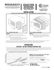
Fig. 6: <strong>Transmitter</strong> Mounting Method Using Four Inch Conduit Box13