AQ/D Duct Air Quality Sensor Data Sheet - Trend Controls
AQ/D Duct Air Quality Sensor Data Sheet - Trend Controls AQ/D Duct Air Quality Sensor Data Sheet - Trend Controls
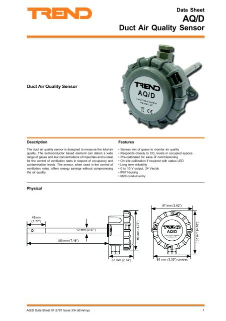
Data SheetAQ/DDuct Air Quality SensorDuct Air Quality SensorDescriptionThe duct air quality sensor is designed to measure the total airquality. The semiconductor based element can detect a widerange of gases and low concentrations of impurities and is idealfor the control of ventilation rates in respect of occupancy andcontamination levels. The sensor, when used in the control ofventilation rates, offers energy savings without compromisingthe air quality.Features• Senses mix of gases to monitor air quality• Responds closely to CO 2levels in occupied spaces• Pre-calibrated for ease of commissioning• On site calibration if required with status LED• Long term reliability• 0 to 10 V output, 24 Vac/dc• IP67 housing• M20 conduit entryPhysical97 mm (3.82”)45 mm(1.77”)190 mm (7.48”)12 mm (0.47”)90 mm (1.77”)AQ/DTrend Control SystemsHorsham, UK105 mm (4.16”)57 mm (2.74”) 85 mm (3.35”) centresAQ/D Data Sheet 91-2797 Issue 3/A dd/mm/yy1
- Page 2 and 3: AQ/DData SheetFUNCTIONALITYThe sens
- Page 4: AQ/DData SheetPRODUCT CODEAQ/DDuct
<strong>Data</strong> <strong>Sheet</strong><strong>AQ</strong>/D<strong>Duct</strong> <strong>Air</strong> <strong>Quality</strong> <strong>Sensor</strong><strong>Duct</strong> <strong>Air</strong> <strong>Quality</strong> <strong>Sensor</strong>DescriptionThe duct air quality sensor is designed to measure the total airquality. The semiconductor based element can detect a widerange of gases and low concentrations of impurities and is idealfor the control of ventilation rates in respect of occupancy andcontamination levels. The sensor, when used in the control ofventilation rates, offers energy savings without compromisingthe air quality.Features• Senses mix of gases to monitor air quality• Responds closely to CO 2levels in occupied spaces• Pre-calibrated for ease of commissioning• On site calibration if required with status LED• Long term reliability• 0 to 10 V output, 24 Vac/dc• IP67 housing• M20 conduit entryPhysical97 mm (3.82”)45 mm(1.77”)190 mm (7.48”)12 mm (0.47”)90 mm (1.77”)<strong>AQ</strong>/D<strong>Trend</strong> Control SystemsHorsham, UK105 mm (4.16”)57 mm (2.74”) 85 mm (3.35”) centres<strong>AQ</strong>/D <strong>Data</strong> <strong>Sheet</strong> 91-2797 Issue 3/A dd/mm/yy1
<strong>AQ</strong>/D<strong>Data</strong> <strong>Sheet</strong>FUNCTIONALITYThe sensor is highly sensitive to gases given off from Volatile Organic Compounds (VOCs) as well as high levels of CO, CO 2, andhigh humidity. The sensor output is 0 to 10 Vdc and increases with the degree of contamination.The air quality sensor is factory calibrated to provide 1 V output in clean uncontaminated conditions.View of <strong>AQ</strong>/D pcb. from connector sidestatus LEDRun/calibrate link (run position)Connector24V 0V OPRunCalDelay PotentiometerLD1 VR1ADJUST DELAY- +VR2View of <strong>AQ</strong>/D pcb. from surface mount sideRun/calibrate link (run position)Status LEDThe status LED under ‘run’ operation provides indication of theaverage sensor condition over the last 96 hours. Thismeasurement is updated every 24 hours. The following providesindication of the sensor condition.LED OFF - sensor condition OKLED FLASHING - sensor output above 4 V continuous.Atmosphere contaminated or sensor needsre-calibration.LED ON - Output above 7 V continuous. Atmosphereseverely contaminated or sensor needs re-calibration.Under calibration operation it provides an indication of outputlevel (see adjacent re-calibration section).Re-CalibrationIf the air quality sensor needs re-calibration this can be achievedby adjusting the calibration potentiometer VR1. If site calibrationis necessary then any adjustments should be made in smallincrements using the following procedure.1. Ensure that the power supply to the sensor has been onfor a minimum of 30 minutes and the environment aroundit is clean, low occupancy, and free from odours andcigarette smoke.2. Change red run/calibrate link from Run (*left to centrepin) to Cal mode (calibration, *centre to right pin).3. The status LED removes the need for a DVM. The LEDindicates the following:OFF - output below 0.9 V,FLASHING - within calibration thresholds,ON - output above 1.1 V.4. If you need to re-calibrate, adjust the TRIM potentiometerVR1 slowly until LED flashes then goes off. The outputvoltage at this level will be 0.9 to 1.1 Volts. Leave for aminimum of 15 minutes and check the output again.5. Repeat step 4 if further calibration is required.6. After the sensor is re-calibrated return the redrun/calibrate link to Run position (*left to centre).*<strong>AQ</strong>/D pcb viewed from connector sideImportant do not over adjust during re-calibration as thiswill cause instability.2 <strong>AQ</strong>/D <strong>Data</strong> <strong>Sheet</strong> 91-2797 Issue 3/A dd/mm/yy
<strong>Data</strong> <strong>Sheet</strong><strong>AQ</strong>/DINSTALLATIONDue to the sensor’s sensitivity to numerous gases, the sensor cannot be rated in ppm across its output range so it is important atthe commissioning stage that the setting up is carried out in clean uncontaminated air.The installation involves:choose an accessible location for the sensor where there is good air movement but is not subject to high air velocitydrill 2 pilot holes at 85 mm centres in duct side to take No.6 20 mm self tapping screws (see template)Ø 15 mm2 pilot holes42.5 mm42.5 mmdrill a 15 mm diameter clearence hole centrally between the 2 screw holesmount sensor on duct, tighten screwsremove lidremove connectorinsert cable through glandcheck link position is ‘Run’connect to controllerturn Delay Potentiometer (VR2) to ‘min’ (fully anti-clockwise)power up and leave for 30 minutes in a clean environment with fan system running, sensor should read between 1 to 3 Vdc,if not recalibrate as aboveturn delay to required level (0-12 mins)set up IQ channel for voltage (V)configure IQ sensor modulestest sensorNote: - The sensor is factory calibrated and should not require adjustment under normal conditions. A burn in period of 2 to 3days is required to ensure a stable and repeatable output.Full installation details are given in the <strong>AQ</strong>/D Installation Instructions TG100525.CONNECTIONS24V 0V OPRunCalLD1 VR1 VR2ADJUST DELAY- +Note that sensor requires 96 mA from 24 V supply24V 0V OPIQ1 or IQ224V (AUX)C (0V)INIQ analogue input channel linkedfor voltage (V)24V 0V OPIQ30 (0V)N (in)24VNIQ analogue input channel linkedfor voltage (V)use auxiliary 24 Vdc output terminal as maximum current = 96 mA<strong>AQ</strong>/D <strong>Data</strong> <strong>Sheet</strong> 91-2797 Issue 3/A dd/mm/yy3
<strong>AQ</strong>/D<strong>Data</strong> <strong>Sheet</strong>PRODUCT CODE<strong>AQ</strong>/D<strong>Duct</strong> air quality sensor.DISPOSALWEEE Directive :At the end of their useful life the packaging andproduct should be disposed of using a suitablerecycling centre.Do not dispose of with normal household waste.Do not burn.SPECIFICATIONElectricalOutputConsumptionPower SupplySensing ElementAccuracyHysteresisSensitivityEnvironmentalOperating limitsMechanical:0 to 10 Vdc(0 V = good quality, 10 V = bad quality):96 mA maximum:15 to 32 V (ac/dc):Tin dioxide semiconductor elementenclosed in flame proof stainless steelhousing.:International standards to be agreed.:Negligible:Dependent on gas mix:Designed for controlled environments(e.g. return air) 18 to 24 °C (64 to 75 °F),65 %RH ±5%.Dimensions<strong>Duct</strong> tube :190 mm long x 12 mm diameterFixing centres :85 mmHead :57 mm deep x 105 mm diameter (max.)Cable entry :M20Enclosure material :Flame retardant (V0) ABS.Connectors:Single part for 1.0 mm (18 to 20 AWG)Weight:170 gm (6 ozs)Protection:IP67Input channels and sensor scalingThe IQ controller’s input channel must be set up for analogvoltage (V), and the sensor type module must be set up with thesensor type scaling. It is recommended to use SET (softwaretool) for the setting of sensor type module. For all IQ2 seriescontrollers with firmware of version 2.1 or greater, or IQ3 seriescontrollers, the following SET Unique <strong>Sensor</strong> Reference shouldbe used:<strong>Air</strong> <strong>Quality</strong> VIf not using SET, use the following table for all IQ2 series controllerswith firmware of version 2.1 or greater or IQ3; for all other IQcontrollers see the <strong>Sensor</strong> Scaling Reference Card TB100521A.Use sensor type scaling mode 5, characterise, with the inputtype set to 0 (volts) and the table below:Y I nput type0 (volts )E Exponent3U Upper100L Lower0P Points2x IxOx1 0 02 10100Manufactured for and on behalf of the Environmental and Combustion <strong>Controls</strong> Division of Honeywell Technologies Sàrl, Ecublens, Routedu Bois 37,Switzerland by its Authorized Representative, <strong>Trend</strong> Control Systems Limited.<strong>Trend</strong> Control Systems Limited reserves the right to revise this publication from time to time and make changes to the contenthereof without obligation to notify any person of such revisions or changes.<strong>Trend</strong> Control Systems LimitedP.O. Box 34, Horsham, West Sussex, RH12 2YF, UK. Tel:+44 (0)1403 211888 Fax:+44 (0)1403 241608 www.trend-controls.com<strong>Trend</strong> Control Systems USA6670 185th Avenue NE, Redmond, Washington 98052, USA. Tel: (425)869-8400, Fax: (425)869-8445 www.trend-controls.com4 <strong>AQ</strong>/D <strong>Data</strong> <strong>Sheet</strong> 91-2797 Issue 3/A dd/mm/yy


