Rendre compatible les techniques traditionnelles et les modernes ...
Rendre compatible les techniques traditionnelles et les modernes ...
Rendre compatible les techniques traditionnelles et les modernes ...
- No tags were found...

You also want an ePaper? Increase the reach of your titles
YUMPU automatically turns print PDFs into web optimized ePapers that Google loves.
<strong>Rendre</strong> <strong>compatible</strong> <strong>les</strong> <strong>techniques</strong> traditionnel<strong>les</strong> <strong>et</strong> <strong>les</strong> <strong>modernes</strong>Compatibilizar técnicas tradiciona<strong>les</strong> y modernasCombining traditional and modern <strong>techniques</strong>The Swabian Village of Termoli. Thevault system: tecniques and recoveryCamilla SansoneArchitect, Ph. in “Technologies for the Building Recovery and theTechnological Innovation”, researcher with biennial scholarship, visitingProfessor to the Faculty of Architecture (Montevideo UY), AssistantProfessor of “Technology for the building recovery” in the Universityof Molise (IT). She publishes volumes and artic<strong>les</strong> about technologicalrecovery of the traditional architecture.E-mail address:camilla.sansone@fastwebn<strong>et</strong>.itTelephone:039 3331127900The ancient Swabian Village of Termoli is the original nucleus of theadriatic town, whose foundation is dated, by archive sources, to theV th century. It was born as an extension of a fortified emplacementpertaining to a system of sighting towers installed to protection ofwraps coastal. This village constitutes an independent entity fromthe modern city, fruit of an expansion plan of the XIX th century. Itpresents uniform constructive characters that have been maintainedunchanged in the centuries. As centre of the Bishopric and a trades portthem Termoli has always been a rich city and this explains the notablecharacteristics present also in the more modest buildings. Apart fromsome of the wealthier buildings like the castle, the cathedral and <strong>les</strong>sernoble mansions, the building of the Swabian Village of Termoli wasborn in order to accommodate merchants and fishermen.The composition of these architectures is strongly conditioned by therequirements deriving from the activities tied to the sea. The buildingsare on three levels: on the ground floor the storage for the equipmentand the stock and a premises with the fireplace; on the first floorthe residence for the family and, in the attic, a ventilated area for theconservation of the provisions. The construction materials from th<strong>et</strong>echnological survey carried out on these buildings show a prevailinglocal origin. The construction stones come partially from still existingquarries, for example the breccia del Gargano. The constructors,instead, show a typical technical formation of the swabian constructiveculture, imported in Italy by the emperor Federico II, that was theinitiator of the construction of the Cathedral of Termoli. The systems ofhorizontal partition of the buildings introduce a rich technological andconstructive vari<strong>et</strong>y. The vault system, frequently used for the realizationof the ceilings of the first level of the buildings, present widely articulatemodalities of organization of the blocks that compose it, rich elaborateand accurate in the geom<strong>et</strong>ric and technical construction. The vaultsystem is found also outside the buildings in the planning of the citysystem. In fact the Swabian Village of Termoli, raised on a limestoneblock nearly entirely encircled by the sea, is exposed to strong winds.For this reason it is delimited by a wide building curtain that protectsthe residential area and is characterized by tight and winding roads,made mostly by means of city passages covered with characteristicbarrel vaults in stone and brick. (img.1)Made in limestone and sandstone stone with disarticulated weavingin the ancient buildings, like the castle and the cathedral, the vaultsassume, in the course of the centuries, more and more elaborateapparatus by use of the brick that, covered with plaster opportunelymixed guarantees a b<strong>et</strong>ter capacity of the horizontal partition system.The simp<strong>les</strong>t vault system is the barrel vault in stone to cover basementsand underground spaces. The construction used a arch lagging in earthshaped with uses of bund<strong>les</strong> of wood, made with stone chips jammedtog<strong>et</strong>her and tied with chalk or lime mortar. The traditional mortarsare based on the baking and the treatment of local limekilns with riversand, in the proportion of 1/3 and 2/3. In order to accelerate the s<strong>et</strong>tingprocesses of the mortar chalk was added, or more often for vaults andhourdis ceiling only chalk mortar was used.The cladding spandrel was realized with a system known as “copertina atre accavallatoi” cover with three levels, that is a filling obtained in threedistinct phases. The first part has the task to fill up the interstices and thesides, the second level renders the surface flat still slightly curve whil<strong>et</strong>he third part finishes the surface destined to receive the pavement.In some cases the upper surface of the vault is left without filling orfilled up with incoherent materials that offer insufficient support, thepavement is supported by an independent ceiling. The beams of thisceiling, supported on the mid portion of the vault below, can be ofreduced dimensions. Structurally different are the vaults placed onthe upper floors: with baked bricks, rectangular pianelle laid on edgehigh 0.15cm united with chalk or lime mortar with sand or volcanicsand (pozzolana), or small hollow floor bricks on lanc<strong>et</strong> or skene archlagging. The geom<strong>et</strong>ric configuration of these vaults generally is ofversatile shape, pendentive dome or pavilion. (img.2) Less frequent ar<strong>et</strong>he groined volts that are found mostly in the covers of the footpaceof the stairsThe use of brick in the coastal area of the Molise widespread thanks tothe presence of clay quarries; in fact the difficulties in the transportsand the inadequate stre<strong>et</strong> n<strong>et</strong> did not favour the transport of theconstruction materials. The activity of brick creation happened near thequarry. The procedure consisted in one first phase in which the clay inpieces was sifted by hand, and then struck with a mall<strong>et</strong> or crumbledunder a stone. After a second passage in the sieves and an addition ofwater the material was pasted with the fe<strong>et</strong> in appropriate pits linedwith bricks. In order to make more valuable bricks the clay was left tosediment for five or six months exposed to the atmospheric agents.Every pit concurred the preparation of approximately 600 bricks. Theconfection of bricks employed of shapes positioned on a surfacecovered with sand or ash in order to facilitate the separation of thefinished pieces. The shapes were rectangular for the making of bricksand pianelle. After the formation the next step was drying exposed tothe air and then baking in appropriate furnaces. The handcrafted bricks,beginning from the 1800 had standard dimensions, with small localvariations. Normally solid bricks and the those with two ho<strong>les</strong> were26x13x7cm while those with three ho<strong>les</strong> were 21x10x4 cm.For the construction of the light vaults and the vaulted ceiling slabsb<strong>et</strong>ween the m<strong>et</strong>allic beams of the ceiling special shaped bricks weremade: these elements, called pignatielli had a cylindrical shape andthey were hollow inside. The last system frequently found, beginningfrom the second half of the eighteen hundreds, the ceilings with ironbeams and small brick vaults. (img.3) A variation of the wood ceiling531
<strong>Rendre</strong> <strong>compatible</strong> <strong>les</strong> <strong>techniques</strong> traditionnel<strong>les</strong> <strong>et</strong> <strong>les</strong> <strong>modernes</strong>Compatibilizar técnicas tradiciona<strong>les</strong> y modernasCombining traditional and modern <strong>techniques</strong>Building and Rebuilding with earth.Earthen architecture in Cyprusand the problem of its conservationDiomedes MyrianthefsSchool of Architecture, NTU Athens, Greece, 1983-89. MA in ArchitecturalConservation, IoAAS, U of York, UK, 1990-91. He has been workingin the conservation of historical buildings field, in Greece and Cyprus,since 1989. He participated in several seminars and congresses in thefield of history and conservation of Byzantine, Post Byzantine andmore modern architectureAddress:13A, Averof st. Strovolos 2063, Nicosia, CyprusE-mail address:dmyri@cy.n<strong>et</strong>Telephone:+357.22.516.447 fax : +357.22.516.449 mob.: +357.99.654.456Historical InformationIt seems that mud brick structures were common in Cyprus from theNeolithic age (7000-6000 BC) to the first decades of the 20 th century,The earliest example of such structures were found at Choirokitia, aNeolithic Age s<strong>et</strong>tlement. Through archaeological investigation andexcavations it was found that adobe was used in several places ofCyprus from the Neolithic, to the Classic Period. The construction ofthose walls is very simple; mud bricks of different sizes and thicknessesare resting on a rubble-stone substructure. This technique continued tobe used throughout the various periods of Cypriot history. Mud brickswere also used in military structures like the Ven<strong>et</strong>ian walls of Nicosia aswell as in some Medieval churches. Adobe as a basic building materialis m<strong>et</strong> mainly today in the rural and urban traditional architecture ofthe 19 th and 20 th c.Types of traditional architectureThe basic rural dwelling in Cyprus is the single-unit structure. Twocan be considered the main types of this. In the plains and in thes<strong>et</strong>tlements of the foothills of the mountains the type that prevails isthe broad-front single-room house (makrinari). The maximum widthof the makrinari varies from 3-4 m<strong>et</strong>ers which is d<strong>et</strong>ermined by theconstructional properties of the timber available where the length ofthe building varies b<strong>et</strong>ween 6-8 m<strong>et</strong>ers or even more. A second basictype of a single-unit house is that in which the almost rectangular room(palati or dichoro) is divided either by a large, often pointed, arch thatsupports the roof or by a wooden post on which the central beam restsand carries either a pitched roof or an almost flat roof. In these casesand according to the timber available the dimensions are about 6X6m<strong>et</strong>ers. Of course the vari<strong>et</strong>y of the islands rural houses is not limited tothe above mentioned basic types. There are many house variations asa result of either successive extensions or additions of auxiliary units tothe basic one. According to the plot and the area available a house wasbuilt and extended as a single-storey building (plains) or in two levels(mountainous regions). In the towns the typology differs, especiallyfrom the end of 19 th century onwards, as neo-classical characteristicswere incorporated both in typology and façade formation. In thiscategory a central common room (iliakos) is surrounded on both sidesby rectangular rooms which with the backyard additions, the verantahs<strong>et</strong>c create a more complex type of dwelling.The structureMud brick constructionAdobe architecture has been mainly used in the plains where soil isplentiful and stone rare and difficult to obtain. Mud bricks were madewith the use of local soil and the addition of binders such chaff, strawand ear as the most common ones. Also goat hair and seaweed wasused depending on the location and availability. The mixture of soil,straw and water was left for few hours up to a day so as cellulose wasreleased to give adhesive properties and make it mouldable. Mud brickswere prepared with the use of a wooden mould of internal dimensions30x45x5 cm and were left to dry for at least a week. Mud bricks wereonly made during the summer.Building with mud bricksThe foundation of an traditional house consist of a mixture of lime, sandand gravel (“limeconcr<strong>et</strong>e”) and was used to fill a trench which was dugfor the purpose. On top of that a stone base foundation is always builtto protect mud brick walls from rising damp. The stone base of thewall, of about 40 cm thick, was built with local stone. The height ofthe stone part of the wall varies, it goes from 1 m<strong>et</strong>er high, up to thelintel of the openings. Mud bricks were then laid in consecutive layerswith intersecting joints. The walls were built with the use of straw basedmortar which was as thin as possible to avoid shrinking and unevens<strong>et</strong>tling while drying. The wall was strengthened and “tied” with theuse of wooden binding beams (mantosia). Mantosia was placed atthe top of the wall, usually at the external side of it. Wooden beamswere also used at the height of the lintels of the openings. The wallswere left to “s<strong>et</strong>tle” for a long period before any kind of coating wasapplied. The most common renders were gypsum on the inside andmud plaster with straw on the outside. From the beginning of the 20 thcentury onwards lime based renderings were used as well. Mud plasteris essential for the protection of the mud brick wall from rain but it hasto be repaired annually when used externally.The causes and effects of decay on mud bricks structuresThe main cause of mud brick, and its render, d<strong>et</strong>erioration is waterpen<strong>et</strong>ration.1. D<strong>et</strong>erioration at the base of the wall. The rising damp pen<strong>et</strong>ratesinto the mass of the wall and depending on the temperaturealterations it is drawn outwards. Thus the evaporating water leavesbehind crystalline salts breaking this way the coherence of thesoil and creates disintegration of the material which is then easilyeroded by wind action. The process continues upwards and inwards,undercutting the wall structure and it may end to a collapse.2. D<strong>et</strong>erioration at the top of the wall. Water pen<strong>et</strong>rates when the533
<strong>Rendre</strong> <strong>compatible</strong> <strong>les</strong> <strong>techniques</strong> traditionnel<strong>les</strong> <strong>et</strong> <strong>les</strong> <strong>modernes</strong>Compatibilizar técnicas tradiciona<strong>les</strong> y modernasCombining traditional and modern <strong>techniques</strong>roof structure at the top of the wall fails. Hair cracks due to excessivew<strong>et</strong>ting gradually develop to channels which become thinnerand die out as they progress downwards. This procedure leads toextensive disintegration of the bricks and to vertical cracking.3. Disintegration of the material. Damp pen<strong>et</strong>rated the wall graduallyevaporates and through the freezing-thawing cycle causes loss ofthe material cohesion which is pulverised and becomes dust.4. Cracking is developed as a result of structural inefficiency du<strong>et</strong>o extrinsic causes like earthquake or due to poor foundationconstruction which causes displacements and bending.5. Human activity. In order to “strengthen” or “protect” the sensitivemud brick material or its stone base from external dump and water,cement plaster was extensively applied. This m<strong>et</strong>hod proved to becatastrophic for the mud wall as the cement render being strongerthan the earthen core does not allow humidity to be released andleads to humidity accumulation in the core of the wall. This leadseventually to the extensive disintegration of the mud brick.Repair m<strong>et</strong>hodsAn intervention on a damaged mud brick structure aims at therestoration of those parts by eliminating the causes of its destruction.Also additional strengthening by means of modern <strong>techniques</strong> mustbe considered if necessary.1. I ntervention on the stone base of a mud brick wall. The mostcommon <strong>techniques</strong> for the strengthening of the stone wall andthe prevention of the rising damp are, the underpinning, theconstruction of a proper drainage system and the grouting by<strong>compatible</strong> injection grout. Stone replacement as well as repointingof the wall are also common practice.2. Repairs in the body of the wall. Heavily damaged mud bricksshould always be replaced. Precaution must be taken in relationwith the “soil compatibility” and the proper bonding of the newwith the existing. Replacements of mud bricks with other materialthan that (fired bricks <strong>et</strong>c) should be avoided as incompatibility mayresult to poor connection.If the damaged part is a corner or is accompanied by cracks a furtherstrengthening m<strong>et</strong>hod must be applied. The most common one is theinsertion of a wooden tie beam at an appropriate length and at severallevels along the height of the wall (stitching). If it is necessary woodentie beams could be inserted on both sides of the wall and should be, inthis case, properly connected b<strong>et</strong>ween them. The same way a properinterlocking of the corners must be inserted if the existing one is notappropriate or does not exist at all. It is of crucial importance to createa proper tie at the top of the wall to establish the diaphragm function.This can be done by the insertion of ring beam(s) where the woodstructure of the roof/floor can rest.Other strengthening m<strong>et</strong>hods that are widely used is the increase ofthe length of the sitting of a wooden beam so as load is distributed ina wider area and the increase of the length and section of the lintelsof the openings. In an extreme case where a wall has a very low loadbearing ability, a timber frame structure (vertical posts and horizontalbeams properly connected) can be incorporated to carry the load ofthe structure.534
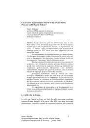
<strong>Rendre</strong> <strong>compatible</strong> <strong>les</strong> <strong>techniques</strong> traditionnel<strong>les</strong> <strong>et</strong> <strong>les</strong> <strong>modernes</strong>Compatibilizar técnicas tradiciona<strong>les</strong> y modernasCombining traditional and modern <strong>techniques</strong>Récupération des TechniquesConstructives Traditionnel<strong>les</strong> Sismo-Résistantes pour un Entr<strong>et</strong>ien du BâtiAncienAmina FoufaDr. Architecte, enseignante-chercheur au Département d’Architecture.2002-2003 <strong>et</strong> 2004- Enseignant invité aux cours intensifs Européenssur la Culture Sismique locale. (CUBEC), Ravello, Italie. 2000- Aujourd’hui –Proj<strong>et</strong> de Recherche IUGS-UNESCO-IGCP Proj<strong>et</strong> 457“Seismic Hazard Assessment in North Africa”. 2007 – Chercheur associéau CNERU, Alger. « Proj<strong>et</strong> : Plan de sauvegarde de la Casbah d’Alger ».Adresse postale :Département d’Architecture, Faculté des Sciences de l’Ingénieur.Université de Blida. BP 270- Blida 09000, AlgérieAdresse courrier électronique :Foufa_a_dz@yahoo.frTéléphone :Tel : + 213 25 415 697 Mob : + 213 71 309 595Introduction :Pour m<strong>et</strong>tre en évidence la résistance des constructions datant de lapériode Ottomane (Alger <strong>et</strong> Tunis) <strong>et</strong> de la période Alaouite (Fès) durantle XVIII ème siècle, une analogie avec ce que préconisent d’une part, lerèglement parasismique actuel pour <strong>les</strong> constructions en maçonnerie<strong>et</strong> une comparaison avec la théorie de la dynamique des structuresd’autre part ont été établies. En eff<strong>et</strong> ces lois sont immuab<strong>les</strong> <strong>et</strong> lecomportement dynamique des constructions de même type est lemême quel<strong>les</strong> que soient <strong>les</strong> périodes.C<strong>et</strong>te démarche à partir de données scientifiques nous a permisd’éviter <strong>les</strong> interprétations hasardeuses en matière de <strong>techniques</strong>parasismiques.Les normes utilisées concernent tous <strong>les</strong> éléments structuraux. Dans lebâti traditionnel ont été pris en considération <strong>les</strong> règ<strong>les</strong> qui régissent<strong>les</strong> constructions en maçonnerie 1 réalisées généralement en mursde commande simple (brique de terre cuite 2 ) ou mixte (briques <strong>et</strong>moellons).Les <strong>techniques</strong> constructives mise en évidence ont permis d’établirque le bâti traditionnel construit après <strong>les</strong> séismes destructeurs n’estpas aussi vulnérable car il répond aux règ<strong>les</strong> des codes parasismiquesactuels établis pour <strong>les</strong> constructions en maçonnerie.Les <strong>techniques</strong> constructives sismo-résistantes :Il a été mis en évidence suite à une lecture archéologique in situà la Casbah d’Alger 3 , dans la médina de Fès <strong>et</strong> celle de Tunis, des<strong>techniques</strong> constructives sismo résistantes qui ont été exécutées suiteau tremblement de terre de 1716 par la communauté d’Alger 3 . Etprobablement depuis <strong>les</strong> séismes de 1624 <strong>et</strong> 1755 à Fès <strong>et</strong> 1758 à Tunis.Ces <strong>techniques</strong> concernent :La typologie constructive de la structure rigide (murs enmaçonnerie) :La structure rigide (murs porteurs) est représentée par des mursde commande en maçonnerie qui peut être classée selon le typede matériaux, la taille <strong>et</strong> la forme des blocs ainsi qu’en typologieconstructive régulière ou irrégulière 4 . Le type principal de maçonnerierencontrés sur <strong>les</strong> différents sites (Alger, Tunis <strong>et</strong> Fès) est : cuite de dimensions variab<strong>les</strong> 3x10x20 cm, 3x12x20 cm, 3x12x25 cm,3.5x12x20cm <strong>et</strong> 4x11x24cm pour Alger 5 <strong>et</strong> 2.5x13x26 cm pour Fès 6 .C<strong>et</strong>te maçonnerie est liée par un mortier de terre ou de chaux. La paroimurale en général a une épaisseur de 60 cm.Ces murs de commande présentent différentes variantes. non équarri de 10 cm de diamètre (thuya Alger 7 , cèdre à Fès 8 <strong>et</strong>genévrier à Tunis 9 ). Le bois dans ce cas-là n’exerce aucune force d<strong>et</strong>raction (Fig 1).C<strong>et</strong>te disposition de deux matériaux, l’un rigide <strong>et</strong> l’autre flexible,perm<strong>et</strong> une absorption des charges horizonta<strong>les</strong> lors des sollicitationssismiques. Par ailleurs, <strong>les</strong> murs présentent peu de fissures <strong>et</strong> ne sedétruisent pas. régulières ou non présentant un « opus mixtum ».Dans ces cas là seule la stratification des matériaux fait baisser lebarycentre global des masses d’où la sismo-résistance de ce type demur 10 .La typologie constructive d’un pilier de voûtes :Les piliers en maçonnerie supportant <strong>les</strong> voûtes sont également réalisésen briques entre <strong>les</strong>quel<strong>les</strong> est insérée une rangée de 4 à 5 rondins d<strong>et</strong>huya à Alger <strong>et</strong> 6 rondins de genévrier à Tunis (fig 2). Ces rondins sontà intervalle régulier variant entre 80 cm <strong>et</strong> 100 cm.A Fès, il semblerait que c<strong>et</strong>te technique soit semblable à celle observéedans <strong>les</strong> deux autres médinas. C<strong>et</strong>te technique a été décrite lors destravaux de restauration de Da r ‘Adyal 11 . Il est dit que des plaques debois sont intégrées tous <strong>les</strong> 50 cm aux sections des piliers assurant ainsila connexion entre <strong>les</strong> piliers octogonaux des rez de chaussée <strong>et</strong> <strong>les</strong>piliers rectangulaires de l’étage. Ces éléments en bois, disent-ils, ontpour fonction d’absorber <strong>les</strong> éventuels désordres générés soit par <strong>les</strong>séismes soit par <strong>les</strong> tassements différentiels du sol de fondation.C<strong>et</strong>te technique semble procurer à c<strong>et</strong> élément structurel sa fonctionsismo-résistante puisque le bois intercalé entre <strong>les</strong> éléments demaçonnerie fait baisser le barycentre global des masses.Les encorbellements :Dans le trois médinas ont été exécutés des encorbellements à l’extérieurdes constructions. Ils résultent d’une extension en profondeur donnantsur la rue, un avant-corps soutenu en étage supérieur par des rondins535
<strong>Rendre</strong> <strong>compatible</strong> <strong>les</strong> <strong>techniques</strong> traditionnel<strong>les</strong> <strong>et</strong> <strong>les</strong> <strong>modernes</strong>Compatibilizar técnicas tradiciona<strong>les</strong> y modernasCombining traditional and modern <strong>techniques</strong>de bois débordant largement du mur. Ces balcons de façade appeléq’bu à Alger <strong>et</strong> Tunis <strong>et</strong> ru sha n 12 à Fès sont soutenus par desrondins de bois formant un angle avec le mur porteur <strong>et</strong> ayant le rôle dejambage. Ce dernier perm<strong>et</strong> à l’encorbellement de ne pas osciller lorsdes secousses sismiques <strong>et</strong> de ne pas se briser. Les rondins de thuya <strong>et</strong><strong>les</strong> poutres de cèdres sont en une constante flexion dynamique (fig 3).Les planchers :Ceux d’Alger sont constitués par une superposition de deux rangéesde thuya insérées dans toute la largeur des murs porteurs créant ainsiune différence de niveau. Entre ces derniers est disposé un voligeageen bois 13 . C<strong>et</strong>te disposition du bois facilite l’absorption des effortshorizontaux lors du mouvement de glissement ou de roulement. Ainsi<strong>les</strong> planchers sont préservésLe détail constructif de la liaison colonne- départ d’arc :Par ailleurs, un détail particulier a été observé uniquement à Alger.Au niveau de l’articulation de la colonne avec l’arc <strong>et</strong> au dessus duchapiteau, il y’a une ou deux rangées de rondins superposées à lamaçonnerie (fig 4). C<strong>et</strong>te disposition de matériaux différents l’un rigide<strong>et</strong> l’autre flexible garantit grâce aux mouvements de glissement unebonne résistance aux cisaillement. Ce détail contribue à la résistancesismique de l’arc algérois.Conclusion : ont été relevées. Le catalogue des <strong>techniques</strong> sismo-résistantesrépond en matière d’entr<strong>et</strong>ien du bâti historique localisé dans <strong>les</strong>régions sismiquement actives à travers <strong>les</strong> opérations de réparation<strong>et</strong> de restauration sismiques. par une utilisation innovatrice des matériaux <strong>et</strong> des <strong>techniques</strong>traditionnel<strong>les</strong> qui soient <strong>compatible</strong> avec le temps, l’existant <strong>et</strong> <strong>les</strong>aléas naturels (séimes). planificateurs, bureaux d’études, architectes, entreprises deréalisation, ingénieurs ...<strong>et</strong>c) de disposer d’une documentationsynthétique, relative aux mesures préventives traditionnel<strong>les</strong> <strong>et</strong> à laprise en charge du risque sismique. développer une culture de la conservation en vulgarisant laméthodologie de mise en évidence des <strong>techniques</strong> préventivesdans <strong>les</strong> universités pour <strong>les</strong> disciplines liées au patrimoine. diffusée par la formation d’ouvriers qualifiés dans le domaine dela conservation <strong>et</strong> favorisera la bonne exécution des <strong>techniques</strong>préventives pour un meilleur entr<strong>et</strong>ien du bâti.dimanche 13 janvier, 7 Ramadan, n°4386-20eme année.4. CORPUS (2001). Architecture Traditionnelle Méditerranéenne. Euromed Héritage.C.D.Rom5. LAVORGNA A (1990). San Lorenzello. La recherché des “anomalies” qui protègent. Ouvragecollectif CUEBC. Ed F. Ferrigni. Nap<strong>les</strong>.6. LIBERATORE D <strong>et</strong> BERNARDINI A (1999). Seismic behaviour, vulnerability and probability ofcollapse of masonry buildings. In GNDT, The Catania Project earthquake damage scenariosfor a high risk area in the Mediterranean. Pp 127-159.7. Ministère de l’habitat <strong>et</strong> de l’aménagement du territoire du Maroc (1978). SchémaDirecteur d’Urbanisme de la ville de Fès (SDU Fès). Dossier technique n° IV.2 : <strong>les</strong> <strong>techniques</strong>traditionnel<strong>les</strong> d’architecture <strong>et</strong> de décors à Fès.8. Ministère de l’Habitat <strong>et</strong> de la Construction, CGS (2003). RPA 99 ; Modificatifs <strong>et</strong>compléments aux Règ<strong>les</strong> Parasismiques Algériennes CDRom9. RANDAZZO, G (1988 ). Le strutture murarie negli edifici del centro storico di Catania,Documenti dell’Istituto Dipartimentale di Architecttura e Urbanistica dell’Unversità diCatania.10. RAVEREAU, A (1985). La Casbah d’Alger <strong>et</strong> le site créa la ville », Sindbad, Paris. 232 p.11. Saadaoui A. (2001). Tunis ville ottomane. Trois sièc<strong>les</strong> d’urbanisme <strong>et</strong> d’architecture. EdCPU, Tunis, 473 p12. TOURI A, AMEZIANE-HASSANI M ET BARBATO G. Le proj<strong>et</strong> pilote de restauration <strong>et</strong> réhabilitation dupalais Da r ‘Adyel à Fès : un exemple remarquable de coopération tripartite. Ed Diagonale,Italie. 158 p.13. ZACEK, M (1996). Construire parasismique, Risque sismique, Conception parasismique desbâtiments, Réglementation, Ed Parenthèses, Marseille, 340p1 RPA 99, Modification <strong>et</strong> compléments 2003 op.cit <strong>et</strong> Zacek (1995) op.cit2 Atelier Casbah (1980) Proj<strong>et</strong> de revalorisation de la Casbah d’Alger, Plan d’aménagementpréliminaire, structure du bâti <strong>et</strong> CORPUS- Euromed Héritage (2001), <strong>les</strong> principesconstructifs, Saadaoui (2003). Tunis ville ottomane trois sièc<strong>les</strong> d’urbanisme <strong>et</strong>d’architecture, pp 291-345. SDU de la ville de Fès (1978). Notes sur <strong>les</strong> <strong>techniques</strong>traditionnel<strong>les</strong> de l’architecture <strong>et</strong> du décor à Fès, pp 1-30.3 Berbrugger (1867). Dans un article faisant une synoptique des tremblements de terreayant affecté Alger, Berbrugger annonce que le système constructif d’Alger datait de1716.4 Randazzo (1988). La strutture murarie negli edifici del centro storico di Catania.Documenti dell’Instituto Dipartimentale di Architecttura e Urbanistica dell’Università diCatania, 16; pp109-143 <strong>et</strong> Liberatore <strong>et</strong> Bernardini (1999). Seismic behaviour, vulnerabilityand probability of collapse of masonry buildings. GNDT, The Catania Project earthquakedamage scenarios for a high risk area in the Mediterranean; pp128-1295 Abdessemed-Foufa (2005) idem, Atelier Casbah (1980) idem <strong>et</strong> CORPUS (2001) idem6 SDU Fès op.cit p 8 <strong>et</strong> p1217 CORPUS (2001), op.cit, Typologie Architecturale, <strong>les</strong> maisons de la Médina d’Alger, p 3 <strong>et</strong>Abdessemed-Foufa (2005) op.cit pp 28-308 SDU Fès, ibidem9 Saadaoui (2000). Op.cit p 31110 Lavorgna (1990). San Lorezello. La recherche des « anomalies » qui protègent. p 5111 Touri, Ameziane-Hassani <strong>et</strong> Barbato (1999), op .cit ibidem12 SDU de Fès op.cit p 2513 Ravereau (1985).La Casbah d’Alger <strong>et</strong> le site créa la ville. P 148.RÉFÉRENCES :1. ABDESSEMED-FOUFA, A, A, (2005). Contribution for a catalogue of earthquake resistanttraditional <strong>techniques</strong> in Northern Africa: the case of the Casbah of Algiers (Algeria).European Earthquake Engineering Journal, 2.05, Ed Patron, Bologne, pp 23-39.2. ATELIER CASBAH, ETAU, UNESCO, PNUD (1980). Proj<strong>et</strong> de revalorisation de la Casbah d’Alger,plan d’aménagement préliminaire, MUCH, Algérie.3. BERBRUGGER A (1867), <strong>les</strong> tremblements de terre algériens, Akhbar, journal de l’Algérie,GLOSSAIRE :Fahs : la région extra murosDa r: maisonq’bu : encorbellementru sha n: encorbellement536
<strong>Rendre</strong> <strong>compatible</strong> <strong>les</strong> <strong>techniques</strong> traditionnel<strong>les</strong> <strong>et</strong> <strong>les</strong> <strong>modernes</strong>Compatibilizar técnicas tradiciona<strong>les</strong> y modernasCombining traditional and modern <strong>techniques</strong>Pilier à TunisDétail articulation colonne - arcBois inséré dans la maçonnerie à FèsEncorbellement à Alger537
<strong>Rendre</strong> <strong>compatible</strong> <strong>les</strong> <strong>techniques</strong> traditionnel<strong>les</strong> <strong>et</strong> <strong>les</strong> <strong>modernes</strong>Compatibilizar técnicas tradiciona<strong>les</strong> y modernasCombining traditional and modern <strong>techniques</strong>The observed seismic damage oftraditional buildings of WesternGreece reinforce the need for theirstrengtheningF.V. KarantoniDr. Civil Engineer, Lecturer of masonry structures at the Department ofCivil Engineering, University of Patras, Greece.Adress:Department of Civil engineering, University of PatrasUniversity Campus,Gr 26500, Patras, GreeceEmail:karmar@upatras.grTelephone:+30 2610 9977781. IntroductionThe traditional buildings in Greece as in the most countries around theMediterranean Sea should be classified in three major groups in relationwith their structural type, which is related to their construction period.The older buildings may consist the first group (type A1). The materialof the structural walls is adobe or stone, the floors and the roof are oftimber joists but som<strong>et</strong>imes the floors are vaulted. The openings are ofa small percentage of structural walls and the height of each storey isrelatively high. These buildings are generally stiff structures with naturalperiods <strong>les</strong>s than 0.10 sec, depending on their height. The secondgroup (type A2) consists of the buildings subsequently constructed ofstone or solid bricks, that contain many and large openings. The floorsand the roof are of wooden joists. These structures are more flexibl<strong>et</strong>han the previous ones, with natural periods higher than 0.20 sec.In the third group (type B) belong the buildings constructed in thebeginning of 20 th century and have an internal reinforced concr<strong>et</strong>eframe and external structural masonry walls, principally of solid orperforated bricks. The floors are of reinforced concr<strong>et</strong>e and the roofis either wooden or composite of bricks supported by steel beams.A characteristic of these buildings is the asymm<strong>et</strong>ry in plane and inelevation. Their natural periods are lower than 0.20 sec.These values of natural periods refer to low rise buildings, which arecommon in Greece. In the present paper the vulnerability of eachtype of building is examined by the means of finite element analyses.The results of the simulations are compared with the data collectedafter earthquakes. Furthermore, simple strengthening <strong>techniques</strong> arerecommended. In addition, an assessment of the widely spreadingintervention, which is the demolition of internal structural walls andthe erection of a new frame of steel or reinforced concr<strong>et</strong>e as a loadbearing system, is made.Group A1 consists of stiff, symm<strong>et</strong>rical stone masonry buildings withrelatively high storeys, and openings of a low percentage of the totalwall surface. The main external characteristic is that all the architecturalelements emphasize the horizontal dimension of the structure. Th<strong>et</strong>ype A2 buildings consist of openings with great percentage of th<strong>et</strong>otal area. These buildings are also more or <strong>les</strong>s symm<strong>et</strong>rical, havelower storeys, and are <strong>les</strong>s stiff than the type A1. The vertical dimensionis emphasized by all means, structural and architectural. The type Bbuildings are of a hybrid type b<strong>et</strong>ween frame structures and structuralmasonry ones. An internal frame of reinforced concr<strong>et</strong>e beams andcolumns supports the reinforced concr<strong>et</strong>e slabs while the externalstructural masonry supports the end of the reinforced concr<strong>et</strong>e beamsand the outer side of the slabs. As a result, these buildings have a littlepercentage of structural walls, but the slab makes them <strong>les</strong>s flexibl<strong>et</strong>han those of type A2. Their seismic behaviour is unpredictable as ashearing failure causes severe damage due to the lack of load bearingwalls but the bending develops light damage to the upper floor.The analyses were linear elastic by means of finite elements m<strong>et</strong>hods.The seismic forces are according to the Greek Aseismic Code [2], whichhas many similarities with the specifications of the Eurocode 8 [1]. Theloading combination includes the dead loads, plus 30% of live loads,the seismic force along a principal direction plus 30% of seismic forcealong the orthogonal direction, each one along positive and negativedirection. In this study, eight seismic loading combinations areconsidered. The results presented correspond to the most unfavourablecombination of each one of the four combinations in each direction,regard<strong>les</strong>s if the outer or inner fibre of the masonry is mainly stressed.Of course, the reverse of seismic action stresses the opposite fibre ofthe wall.2. Buildings of type A1In situ inspections have shown that the main reason for seismic damageof these stiff structures is the out of plane bending of the upper storeywhich develops vertical cracks near the upper parts of the corners du<strong>et</strong>o the separation of orthogonal walls and almost vertical cracks of thelintels and of the top of the walls. Also, diagonal cracking of the lowerstoreys piers and of the strong lintels is observed [6,7].The results of an analysis of such a building are presented in Fig. 1. Thebuilding is of stone masonry with only one internal load bearing wall inthe two lower storeys along the x direction. The tensile strength of thestone masonry was estimated to be 0.25 MPa. The building is stiff withnatural periods Τ x=0.07 sec and T y=0.1 sec along the x and y direction,respectively. The contours represent the principal tensile stressesdeveloped in the external fiber of masonry. As shown, the regions ofthe masonry walls with tensile stresses exceeded 0.25 MPa are thosepredicted to be most vulnerable.A simple m<strong>et</strong>hod to strengthen this building is to add a structural wallalong the y direction up to the roof level as well as to raise the existinginternal wall to the same level. As shown in Fig. 2, this easy to makeintervention, results in decreasing the principal tensile stresses up to50%. In addition, after the intervention, only a few elements of the walldevelop principal tensile stresses that exceed the tensile strength ofmasonry.A usual modern intervention in order to rehabilitate traditionalbuildings is the demolition of the internal load bearing walls and thepreservation only of the external shell of the building. A new framing538
<strong>Rendre</strong> <strong>compatible</strong> <strong>les</strong> <strong>techniques</strong> traditionnel<strong>les</strong> <strong>et</strong> <strong>les</strong> <strong>modernes</strong>Compatibilizar técnicas tradiciona<strong>les</strong> y modernasCombining traditional and modern <strong>techniques</strong>fig 1afig 1bfig 4afig 4bfig 2afig 2bfig 5afig 5bfig 3afig 3bfig 6afig 6bFig1: Building of type A1. Principal tensile stresses of outer fibers due to:(a) G+0.3Q+E x +0.3E y , and (b) G+0.3Q+0.3E x +E y seismic actionFig2: Building of type A1. Principal tensile stresses after adding structural walls, of outer fibersdue to: (a) G+0.3Q+E x +0.3E y , and (b) G+0.3Q+0.3E X+E y seismic actionFig3: Building of type A1. Principal tensile stresses after demolition of internal structuralwalls, of outer fibers, due to: (a) G+0.3Q+EX+0.3EY, and (b) G+0.3Q+0.3EX+EY seismic actionFig4: Building of type A2. Principal tensile stresses for (a) inner fibers due to G+0.3Q-E x -0.3E yseismic action , and (b) outer fibers due to G+0.3Q-0.3E x +E y seismic actionFig5: Building of type A2. Principal tensile stresses after adding structural walls for (a) innerfibers due to G+0.3Q-E x -0.3E y seismic action, and (b) outer fibers due to G+0.3Q-0.3E x +E yFig6: Building of type A2. Principal tensile stresses after demolition of internal structuralwalls for (a) inner fibers due to G+0.3Q-E x -0.3E y , and (b) outer fibers due to G+0.3Q-0.3E x +E yseismic action seismic actionfig 7afig 7bfig 8afig 8bFig7: Building of type B. Principal tensile stresses for inner fibers due to (a) G+0.3Q+E x -0.3E yseismic action, and (b) G+0.3Q+0.3Ex+Ey seismic actionFig8: Building of type B. Principal tensile stresses after the interventions for inner fibers du<strong>et</strong>o (a) G+0.3Q+E x -0.3E y seismic action, and (b) G+0.3Q+0.3E x +E y seismic action540
<strong>Rendre</strong> <strong>compatible</strong> <strong>les</strong> <strong>techniques</strong> traditionnel<strong>les</strong> <strong>et</strong> <strong>les</strong> <strong>modernes</strong>Compatibilizar técnicas tradiciona<strong>les</strong> y modernasCombining traditional and modern <strong>techniques</strong>A proposal for the development of th<strong>et</strong>raditional construction crafts in EgyptA case study of Aswan CityDiaa-Eldin Ibrahim Mohamed Hanafi,Sherif Mohamed Rabie KhashabaDr. Diaa-Eldin Ibrahim Mohamed Hanafi:Faculty of Engineering, Ain-Shams UniversityDr. Sherif Mohamed Rabie Khashaba:Faculty of Engineering, Zagazig UniversiyResearch Problem:Through studying the current situation of traditional crafts in Aswanwe find a clear shrinking in this new constructional result due to therecession of traditional construction crafts and the overwhelming ofnon local construction ways over stable construction ways.Research Targ<strong>et</strong>:Offering a proposal to develop traditional construction crafts in thegovernorate of Aswan to match modern needs as well as to maintainlocal identity.Research M<strong>et</strong>hodology:The research was based on a theor<strong>et</strong>ical m<strong>et</strong>hod to recognize the localconstruction crafts existing in Aswan, their progress, and the transferof expertise. Along with conducting a practical study of constructionmodels expressing the architectural heritage existing in Aswan tocome up with the architectural specifications and local m<strong>et</strong>hods ofconstruction and to recognize its positive as well as negative aspectsand also to know the extent to which soci<strong>et</strong>y accepts them, then toanalyze the previously mentioned points and to come out with asuggestion to develop inherited traditional ways of construction,to match modern requirements, and then to apply this m<strong>et</strong>hod to acurrent projects and measure the extent to which users will accept it aswell as the extent to which it will contribute to improve the standard oftraditional crafts in Aswan.1- Types of traditional construction crafts in Aswan:A variable collection of traditional crafts in Aswan were located asfollows: fig(1). 2- Reasons for the d<strong>et</strong>erioration Of the traditional constructioncrafts decline in Aswan: crafts restructuring. due to aversion from many people to work in traditional crafts. modern construction systems as an aspect of social prestige. building. required for the usage of traditional construction crafts.3- Proposed m<strong>et</strong>hodology for developing and maintainingtraditional crafts in Aswan:After analyzing this research, m<strong>et</strong>hodology for preserving the traditionalcrafts in Aswan is proposed and it is as follows:Levels of proposedm<strong>et</strong>hodologyLegislation level Economical level Artistic level Cultural and social level3-1 Cultural and social level: depending on the traditional crafts. 3-2 Technical level: m<strong>et</strong>hodologies and <strong>techniques</strong> of the traditional crafts. would be economically. maximize the benefits of the end product. craftsmen traditional crafts and supplying them with the various technical support3-3 Economical level : total cost of construction. crafts, to increase it. to spread the knowledge about it3-4 Legislation level: the building cost to using traditional crafts541
<strong>Rendre</strong> <strong>compatible</strong> <strong>les</strong> <strong>techniques</strong> traditionnel<strong>les</strong> <strong>et</strong> <strong>les</strong> <strong>modernes</strong>Compatibilizar técnicas tradiciona<strong>les</strong> y modernasCombining traditional and modern <strong>techniques</strong> concerning traditional crafts.4- Practical application for proposed m<strong>et</strong>hodology in a familyresidential housing Project:“El herbiyab” projects in Aswan where designed by a two researchers tosupport the use of traditional crafts in building, fig(2).4-1 “ Al-HERBIYAB” VILAGE PROJECT :The project aim to construct family houses, under the national housingproject in Aswan including 500 units.4-1-1 Purpose of project:Support for traditional crafts existing in Aswan through a project thatuses traditional crafts in a wide range which does the following: means of construction using timber, masonry, stone or clay. through incorporating them in big scale projects. crafts could be. 4-2 Studying the applications of the proposed m<strong>et</strong>hodology inproject (after Construction of the proposed project):4-2-1 Craftsmen:A lot of opportunities were made available for the craftsmen , newcraftsmen were trained to preserve the new traditional crafts.4-2-2 The general Style used in buildings:IT was taken in consideration the local identity and the local styl<strong>et</strong>hrough using their same style in the design to produce a secure,healthy and comforting living Place that will attract them to buy newunits with the same style.4-2-3 Construction m<strong>et</strong>hod:All units used a wall bearing m<strong>et</strong>hod, using stones and covering spansusing vaults and domes built from bricks, , which also decreases cost asno exterior finishing is needed.4-2-4 Using natural and local materialsNatural stone was used ,which is abundant in to build walls and vaults,also the windows and doors used local timber , manfactured in a localm<strong>et</strong>hod ,the pergolas also where made from palm leaves and strawwhich was done by local craftsmen.4-2-5 Inhabitants participation:Project includes the participations of the users in design andconstruction process4-3 Implementing the proposal:4-3-1 Social level the project using traditional building systems and crafts. The tworesearchers, the governor, the officials and the popular leaders haveparticipated in these me<strong>et</strong>ings. advantages of the houses which are built using the local crafts.4-3-2 Technical level construction systems, local materials, participation of the localtechnicians who are specialized in the local systems and crafts. using the local systems and crafts that includes constructionsystems, local building materials and local crafts. by developing a system of scaffold and wooden moulds to achieveb<strong>et</strong>ter performance and saving time. for one hundred non skilful workers. 4-3-3 Economical level Euros by changing the roofing from reinforced concr<strong>et</strong>e to brickvaults, fig(3).4-3-4 Legislative levelAn official approval for building the project using local building systemsand local crafts has been obtained and this generates a new officialprincipal to a lease to build by using local building systems and crafts.4-4 Results workers if they built the project using contemporary constructionsystems, fig(4). building craft. building crafts. the local crafts that from 500 houses to 4000 houses. 600 houses extra by the same construction systems and crafts. Aswanian culture and a unique architectural character.Recommendations: internationally. crafts internationally. world wide. revive Traditional Crafts. Traditional Crafts.542
<strong>Rendre</strong> <strong>compatible</strong> <strong>les</strong> <strong>techniques</strong> traditionnel<strong>les</strong> <strong>et</strong> <strong>les</strong> <strong>modernes</strong>Compatibilizar técnicas tradiciona<strong>les</strong> y modernasCombining traditional and modern <strong>techniques</strong>REFERENCES:http://www.fekrzad.com/library/8227http://www.kenanaonline.com/page/3173RAAFAT, A., Future Architecture, Published by Inter-consult Research Center, Giza, Egypt,2007.FATHY, H., Natural Energy and Vernacular Architecture, Arabic edition published ,Beirut, 1988.Modern Architecture b<strong>et</strong>ween Imitation and Renovation, Abenaa Magazine Vol.83, Riyadh,Kingdom of Saudia Arabia 1995.http://www.smartwebonline.com/NewCulture/cont/018300200009.aspIBRAHIM, A. Arab Architects- Hasan Fathy, Center for Planning and Architectural Studies, Cairo,1987.http://www.kenanaonline.com/page/82279Hakim. O., Nubian Architecture, the Palm Press, Cairo, Egypt, 1999.Fig(3) The preliminary design Skelton building, which is changed by two researchersFig(1) Samp<strong>les</strong> of Traditional crafts used in buildings in Aswan.Fig(2) “El herbiyab” projects in Aswan after construction, where designed by a tworesearchers to support the use of traditional crafts in building.Fig(4) brick vaults users in project.543
<strong>Rendre</strong> <strong>compatible</strong> <strong>les</strong> <strong>techniques</strong> traditionnel<strong>les</strong> <strong>et</strong> <strong>les</strong> <strong>modernes</strong>Compatibilizar técnicas tradiciona<strong>les</strong> y modernasCombining traditional and modern <strong>techniques</strong>Repair and Maintenance guidelines forthe inhabitants of a historical district:Papaz Mahal<strong>les</strong>i in Yeni Foça, IzmirEge Uluca TumerPhD in Architecture, Department of Architecture, Restoration andConservation of Historical Buildings Programme, ITUMSc in Architecture, Department of Architecture, Restoration andConservation of Historical Buildings Programme, METUBA in Architecture, Faculty of Architecture, Department of Architecture,METUResearch Assistant in Design, History of Art and Architecture, RestorationCourses, İstanbul Kultur University, IstanbulAddress:İstanbul Kultur University, Atakoy Kampusu Bakırkoy IstanbulE-mail address:egeuluca@superonline.comTelephone:e.ulucatumer@iku.edu.tr0-216-4501705 0-532-4528218 0-216-4984293IntroductionTraditional buildings in Turkey are at risk mainly because of harmful/lackof repairs due to the deficient knowledge of the users and craftsmen.Studies on the preparations for repair and maintenance guidelines areneeded for the continuity of traditional historic sites in Turkey.Papaz Mahal<strong>les</strong>i was found suitable for a case study on ‘developingproper m<strong>et</strong>hods and <strong>techniques</strong> for repair and maintenance problemsand guidelines for users’, for reasons such as its values and specificproblems. Papaz Mahal<strong>les</strong>i (Figure.1) is a well preserved 19 th centurys<strong>et</strong>tlement in Yeni Foça, a small town located north of Izmir. Thestudy area, comprising fifty-six traditional masonry buildings, showsarchitectural and s<strong>et</strong>tlement characteristics of its period in the AegeanRegion. The values of Papaz Mahal<strong>les</strong>i are categorized under six tit<strong>les</strong>;“Aesth<strong>et</strong>ic Value”, “Value for Architectural Diversity”, “Value for FunctionalDiversity”, “Resource Value”, and “Value for Continuity of Cultural Memory/Heritage”, “Value for Uniformity in Architectural Style” (1).1. Problems in Papaz Mahal<strong>les</strong>i1.1. Str uctural System ProblemsAlthough there are not many serious structural problems in buildings,some unique cases have been taken into consideration for theevaluation of structural problems (Figure.2).1.1.1. Interior Structural Problems and Their CausesInterior structural problems documented in the area are mostlydeformation problems in floors, slight deformations of interior walls.More serious problems have emerged in unused and not maintainedbuildings in the area. Loss of mortar, plaster and other binders are theprimary cause of external wall movements that cause interior structuralproblems, as well. However, rigidity of external walls is sufficient for therigidity of structural system.1.1.2. Exterior Structural Problems and Their CausesExterior structural problems are mainly small structural cracks anddeformations on external walls. Emptied joints and loss of binders ar<strong>et</strong>he most important factors that may cause a weakening in these 80-90cm thick walls. As the deformation of walls with emptied joints hasled to the collapse of façades in other historic sites of the town, thisproblem must be taken into consideration rapidly as a primary problemfor the structural systems.1.2. Problems of MaterialsMaterials are visually examined by grouping the problems of eachmaterial in order of emergency. Problems of materials are documentedon 1/100 stre<strong>et</strong> elevations (Figures.3-4) and 1/200 plan (Figure.2). Stone,timber, mortar, plaster, iron, roof ti<strong>les</strong> and paint are recorded accordingto the visual observations made.1.2.1. Decay Forms of StoneThe decay forms of stone is visually recorded and classified accordingto the classification of Fitzner <strong>et</strong> al (2).Stone decay was d<strong>et</strong>ected atlower levels of the buildings, areas under the eaves and on the corners.Discoloration, crusts and salt deposits on stone surface are the mostwidely seen problem types on these areas. The effects of rainfallpen<strong>et</strong>rating the surface under the eaves are very clear. The otherproblematic area is the lower level of the buildings where materiallosses, flaking, discoloration, crusts and soiling are visible. Besides these,rising damp causes joint loss in the upper levels and serious problemsin the whole structure by loss of its binders (Figures.3-4)1.2.2. Timber ProblemsObserved problems on timber are due to the lack of maintenance– preservative waxes, polishes. The problems of structural timber andarchitectural timber differ in the area and evaluated in different subgroups(Figures.3-4).Structural Timber Problems: There are not any serious problems ofstructural timber, except in some empty buildings. In three buildings,floor deformation is documented. Roofs have been observed to bequite firm. Ceilings, if maintained, preserve their properties in goodcondition.Architectural Timber Problems: Capillary cracks and discoloration as a resultof damp are found especially on shutters. The man-made problems aremost common like the bursting and deformation of shutters. Externaltimber architectural elements, exposed to environmental conditions,have more problems like discoloration, capillary cracks, deformationand material loss.1.2.3. Mortar ProblemsMortar is the material having the most severe problems (Figures.3-4).Loss of mortar b<strong>et</strong>ween the joints is especially seen on the walls, fromwhich the plaster is compl<strong>et</strong>ely d<strong>et</strong>ached. Slight deformations on thewalls with emptied joints have been inspected. At the advanced stage544
<strong>Rendre</strong> <strong>compatible</strong> <strong>les</strong> <strong>techniques</strong> traditionnel<strong>les</strong> <strong>et</strong> <strong>les</strong> <strong>modernes</strong>Compatibilizar técnicas tradiciona<strong>les</strong> y modernasCombining traditional and modern <strong>techniques</strong>of mortar loss, material loss of stones occurs.1.2.4. Plaster ProblemsThe plaster problems are classified into four categories; “loss of plaster”,“d<strong>et</strong>achment from wall surface”, “salt deposition” and “discoloration”. Likestone the worst problems are areas under eaves, lower levels of frontalwalls, and corners of the jambs due to dampness. Soiling and crusts arealso seen deposited on plasters.Loss of plaster is the first stage of increasing decays on building façades.Where plaster is d<strong>et</strong>ached, stone and mortar are prone to problems.As plaster is the protective layer, the maintenance of plaster is veryimportant. As the stones of these buildings are closer to cut-stone, theydo not l<strong>et</strong> exterior partic<strong>les</strong>, salts and humidity in as much as the roughcut stones.1.2.5. M<strong>et</strong>al ProblemsThe m<strong>et</strong>al elements are iron in all of the traditional buildings. Problemsof m<strong>et</strong>als do not show much vari<strong>et</strong>y. Oxidation, inspected especially onshutter hinges, and supports is the main problem. Almost all unpaintediron elements, like doors and shutters, are oxidized.2.Proposals for Repairs of the Studied BuildingsAs a result of the studies on building materials, and repair problems,guidelines are formed for different types of repairs that are widelyneeded in the studied buildings. Proposals for these repairs andmaintenance are prepared to be used as guidelines for users and aconservation program.2.1. Cure of Rising DampThere are two sources of water causing rising damp: rainfall andunderground water. The comprehensive m<strong>et</strong>hod of overcoming theexcess water is a b<strong>et</strong>ter drainage system. ventilation, rather than a monolithic one having cement mortar asbinder”, and bottom in front of the base of the damp buildings to reduce thecapillary action”.2.2. Masonry RepairsDuring the repair of masonry, a minimum of stone replacement mustbe done. The new stones are often more difficult to maintain than theold stones. Repair work to be done to these masonry buildings is gapfilling rather than consolidating. Only the buildings, which lost plasterand mortar in joints, started to have small loss and d<strong>et</strong>achment of stoneproblems. There emerged small gaps and cracks, which may weakenthese stones. The stones with special craftsmanship such as inscriptions,panels, keystones, jambs, architraves and some of the eaves needs gapfilling or consolidation work.“Using <strong>compatible</strong> mortars with stones”, and “taking care of esth<strong>et</strong>icalharmony b<strong>et</strong>ween mortars and stones” must be considered while gapfilling.2.3. Grouting and Re-pointingGrouting seems to be a appropriate m<strong>et</strong>hod for some of the buildings,which have compl<strong>et</strong>ely emptied joints and probably have voidsb<strong>et</strong>ween the layers. Similar building types have collapsed and provedthe severity of the problem. Although grouting is not widespread inTurkey, it is the best m<strong>et</strong>hod for consolidating these buildings.Grouting Masonry Walls: The consolidation of historic masonry involvesthe need to stabilise walls by filling voids within their thickness. Thisoperation is most commonly needed when thick walls of doub<strong>les</strong>kin construction, with rubble core filling, have been subject tothe percolation of water for many years. The important point inconsolidating the masonry with a liquid binder is to select a binder thatis <strong>compatible</strong> with stone and former mortar.Re-pointing.: Re-pointing should be carried out immediately to preventthe rapid weathering of the stones. When the mortar in the joints isweathered, the stones become vulnerable to damage and material losson stone surfaces are seen.Permeability, porosity, density and other properties of mortar and stonemust be recorded. When the mortar is <strong>les</strong>s permeable and <strong>les</strong>s porousthan stone, it acts like a vapour barrier in the wall, causes a continuousvapour flow into the stone and prevents evaporation. A permanentdampness can occur in stone that is very harmful. Cement basedmortars in contact with stone can introduce sodium or potassiumsulphate (3) and must be avoided, not only in the preparation of mortarbut also in every stage of repairs.Re-pointing is an advanced type of work, and must be done byqualified workers. Flush filling will greatly increase the apparent widthof the joint, and therefore great care must be taken to keep the layer ofthe new mortar within the original width. mortar.2.4. Plastering and PaintingPlastering: After grouting and re-pointing, plastering the external wallsis necessary. All of the buildings in the area need plaster repairs, exceptthe ones that have never been plastered. The properties of plaster mustbe <strong>compatible</strong> with former plaster and stone. If the plaster is moreporous than stone it weakens quickly and if it is <strong>les</strong>s porous it causes thed<strong>et</strong>erioration of stone by transporting salts and vapour. The criteria forinterior and exterior plasters do not change, while their composition isdifferent due to the different conditions in and outside the buildings.Painting: Painting is the last step of the maintenance of the walls.Besides the compatibility of properties of paint with the plasters andstones, colours have to be carefully selected for the harmony with theother paints in the district. Some of the plasters in the site are colouredwith original colours extracted from plants and earth (indigo, madder,i.e.)2.5. Timber Repair and ConsolidationStructural timber elements like floors and roofs more urgently needattention and must be solved immediately. The main works to be donefor the maintenance of the timbers are;Local or Total Replacements of Timber Elements with New Timber:545
<strong>Rendre</strong> <strong>compatible</strong> <strong>les</strong> <strong>techniques</strong> traditionnel<strong>les</strong> <strong>et</strong> <strong>les</strong> <strong>modernes</strong>Compatibilizar técnicas tradiciona<strong>les</strong> y modernasCombining traditional and modern <strong>techniques</strong>Substitute timber must be the original type of wood and themoisture content of it must be limited in low percentages. Newtimber must be the treated with insecticides. Replacements mustbe limited within least possible amount.Treatment of Infested or Infected Timbers: Infested or infected timberelements must be treated against insects, dry rot or w<strong>et</strong> rot.Extraction of moisture from infected timber and providing adequateventilation must be done before treating with fungicidal paste.Similarly, insecticidal pastes may be applied to infested timbers.Application of Timber Preservatives: For improving the strength andthe resistance of timber elements against external conditions, theymust be applied proper kind of preservatives, paints, insecticidal/fungicidal pastes after various studies and researches on them.2.6. M<strong>et</strong>al RepairsThe traditional m<strong>et</strong>hod is painting for preventing m<strong>et</strong>als from corrosion;however, there are other works to be done before paintingm<strong>et</strong>al elements, manual preparation (removal of rust, loosening millsca<strong>les</strong> and soluble corrosion salts) of m<strong>et</strong>al surfaces by using variousmechanical and chemical m<strong>et</strong>hods considering “not to lose d<strong>et</strong>ailson surfaces of m<strong>et</strong>als”. properties, intermediate and finishing coats of paint must beapplied, taking care not to harm or change its properties.2.7. Roof RepairsRoofs: The structural timber elements must be repaired, by consideringthe important points mentioned for timber repairs. Replacement of thebroken and missing ti<strong>les</strong> must be done with same type of roof ti<strong>les</strong>.REFERENCES(1) TIESDELL, S.; OC, T.; HEATH, T. (1996), Revitalizing Historic Urban Quarters, Martnolls Ltd, UK.p.11-16(2) FITZNER, B.; HYPERLINK “http://webserver.lih.rwth-aachen.de/lih/content/e27/e34/e2876”Heinrichs, K.; Kownatzki, R. (1992), Classification and mapping of weathering forms . In:Proceedings of the 7th International Congress on D<strong>et</strong>erioration and Conservation of Stone,Lisbon, 15.-18.06.1992, Lisbon (Portugal), S. 957-968.(3) FEILDEN, B. M. (1989), Conservation of Historic Buildings, Butterworths, London, p.324546
<strong>Rendre</strong> <strong>compatible</strong> <strong>les</strong> <strong>techniques</strong> traditionnel<strong>les</strong> <strong>et</strong> <strong>les</strong> <strong>modernes</strong>Compatibilizar técnicas tradiciona<strong>les</strong> y modernasCombining traditional and modern <strong>techniques</strong>Traditional Construction TechniquesRevaluation of «Good Practice Rule» forSustainable ConstructionEzilda CostanzoPhD (1998) and building engineer degree (1993) at University of Palermo.Work activities on building pathology and renovation, architectur<strong>et</strong>echnology, sustainable buildings and cities both independentlyand within different research institutions in Italy and in Switzerland(since 2004)Addresse:Ecole Polytechnique Fédérale de Lausanne, Laboratoire de Construction<strong>et</strong> Conservation,EPFL-LCC1, Bâtiment BP, Station 16, CH-1015 Lausanne, SwitzerlandE-mail :ezilda.costanzo@epfl.chTéléphone :0041.(0)79.2978845IntroductionThe Mediterranean area has been characterised, since ancient times,by technical knowledge and stylistic exchange influences. Migrations,conquests, commercial links allowed more advanced constructionalcultures to spread, in different historical periods, even at relevantgeographic distance and beyond the Basin itself. During EuropeanMiddle Ages, as instance, the weight of Roman art on Romanesquearchitecture in France, Byzantine influence on figurative and decorativearts in Germany, France and Italy, Islamic art rule in Southern Spainand Southern Italy can be cited. Multicultural contact Europeanterritories like Southern Spain and Italy were interesting demonstrativelaboratories of imported <strong>techniques</strong> adoption and combination, as wellas of sty<strong>les</strong> amalgamation (mudejar art). In such contexts, foreign goodtechnical ru<strong>les</strong> have been locally assumed by adapting materials andaccustomed practice. Such variations can be seen as the consequenceof a process of optimisation of material and economic resources whichentails what we could presently call “improvement of sustainabilityperformances”.Since the Renaissance, and more systematically since XVIII century,the habit began to classify architecture constructional and formalru<strong>les</strong> in treaties and manuals. The Grand Tour, the Grand Prix ofRome 1 and afterwards more frequent and southwards travels in theBasin, had permitted direct observation, study and representation ofMediterranean buildings in Voyage Carn<strong>et</strong>s. They were drafted in d<strong>et</strong>ailand hypoth<strong>et</strong>ically reconstructed by scholars and Beaux Arts academystudents 2 interested in ancient Greek and Roman construction issuesbut also in vernacular examp<strong>les</strong>.Manuals and treaties contain a precious structured repertoire ofinformation on common traditional <strong>techniques</strong> in the Mediterraneanbasin. Up to the I World War, French and Italian textbooks - the presentstudy refers to some of them, - endorsed architectonic identity of localexamp<strong>les</strong> that were directly surveyed with reference to analoguesapplications in ancient well known buildings. Local idiom were codifiedin these “illustrated dictionaries of construction art”, where classicaluniversal rule is taken into account too. Furthermore they give d<strong>et</strong>ailson durability and quality of different materials and <strong>techniques</strong> and putinto-workpractices, references to cost and material depl<strong>et</strong>ion and useoptimisation. At any rate transportation, material availability, recyclingand recovering concerns were always dealt with in pre-modernbuilding contracts and documents.The paper investigates some issues of “sustainability” which wereimplicit in traditional <strong>techniques</strong> of construction by taking into accountprescriptions in manuals and existent case studies. Local traditionalru<strong>les</strong>, only partially deducible from manuals, are to be integrated, infact, by data coming from direct survey in order to verify local variations,efficacy and related durability performances.Good practice Rule and Sustainability Princip<strong>les</strong> inMediterranean ConstructionStone MasonryStone for structural walls - almost 70% material in a traditional masonryconstruction, - was accurately chosen. For minor constructions andvernacular architecture adoption of undressed stone available on site,rejected or coarse roughly dressed stone consented to save moreprecious quarried stone for ashlars.Rubb<strong>les</strong> were picked up from closest plots of land and selectedaccording to dimension and weight. They were proportional tomason’s strength (25-30 kg) and easy to handle (35-40 cm). They wereafterwards arranged in the building yard into five separate pi<strong>les</strong> ofstones, for rational and ergonomic putting into work. Undressed stonesmight have different origin, hardness and permeability: cold volcanicor m<strong>et</strong>amorphic, quarry offs<strong>et</strong>, live splinters from crushing, irregularfragments picked up below rock faces. Reuse materials frequently camefrom ramparts or more ancient existing constructions.In the traditional building site nothing had to be spoilt and discharged:inert wastes were used to form thin walls at upper levels (15-35 cm)and infill. The stuffed wall, where the core b<strong>et</strong>ween the two externalmasonry workform walls was filled with mortar and stone rubble,belonged to Mediterranean tradition since ancient Rome (II centuryb.C.). It has spread in Mediterranean humble or minor constructionsuntil XIX century, assuring quickness and economy when put intowork.Roofs and floorsManuals classify pitched roofs secondary timber frame accordingto kind of support of roof covering: Steep battens roof (piemontesestyle); horizontal counter batten roof; timber-decking board, terracottaflat ti<strong>les</strong> or stone slabs. All the systems preview maintenance andpartial replacement of timber components, that were pre-squared,prefabricated and ready to be assembled on site. Carpenters used tomark them to facilitate their putting into work. Type and dimensionsof secondary roof frame differ according to countries and resourcesavailability.547
<strong>Rendre</strong> <strong>compatible</strong> <strong>les</strong> <strong>techniques</strong> traditionnel<strong>les</strong> <strong>et</strong> <strong>les</strong> <strong>modernes</strong>Compatibilizar técnicas tradiciona<strong>les</strong> y modernasCombining traditional and modern <strong>techniques</strong>MONROY J.F., Traité d’architecture pratique, Paris 1785 (reprint Genève 1973).RONDELET J.B., Traité théorique <strong>et</strong> pratique de l’art de bâtir, Paris 1802-17.REYNAULD L., Traité d’architecture, Paris, 1850-60.RAMÉE D., L’architecture <strong>et</strong> la construction pratique, Paris 1868.CLAUDEL J. <strong>et</strong> Laroque L., Pratique de l’art de construire, Paris 1910.CLOQUET L., Eléments de l’architecture. Types d’édifices – Esthétique, composition <strong>et</strong> pratique del’architecture, Paris <strong>et</strong> Liège 1911.BARBEROT F., Traité de constructions civi<strong>les</strong>, Paris 1912.BREYMANN, Trattato generale di costruzioni civili, (trad. G. Valentini), Milan 1884.MUSSO E COPPERI, Particolari di costruzioni murali e finimenti di fabbricati, Turin 1885.FORMENTI C., La pratica del fabbricare, Milan, 1893.DONGHI D., Manuale dell’archit<strong>et</strong>to, Turin 1925.BENFRATELLO S, Lezioni di tecnologia delle costruzioni edili, Pisa 1929.GIOVANNONI, Corso d’Archit<strong>et</strong>tura, Rome, 1932.549
<strong>Rendre</strong> <strong>compatible</strong> <strong>les</strong> <strong>techniques</strong> traditionnel<strong>les</strong> <strong>et</strong> <strong>les</strong> <strong>modernes</strong>Compatibilizar técnicas tradiciona<strong>les</strong> y modernasCombining traditional and modern <strong>techniques</strong>Present and Future of Solar Controlwith Photovoltaic Components inMediterranean Architecture in TurkeyMujde AltinI work as an Assistant Proffesor at Dokuz Eylul University Faculty ofArchitecture Department of Architecture Structure and ConstructionBranch. I had my B.Sc., M.Sc. and Ph.D. degrees also in the samedepartment. My working area is solar architecture, use of shadingdevices in architecture, integration of photovoltaics into architecture.Address:Dokuz Eylul University Faculty of Architecture Department ofArchitecture Tinaztepe Kampusu Dogus Cad. No: 209 Kurucesme 35160Buca Izmir TURKEYE-mail address:mujde.altin@deu.edu.trTelephone:00 90 232 412 84 481. Introduction:Buildings are constructed to be a shelter for people. They have toprovide comfort conditions for the people as well as being a shelter.This is due to the fact that human beings are not well protected againstenvironmental and climatic factors. Some animals have fur and this furprotects them from cold weather. But human beings are not as lucky asthose animals. They have to provide these conditions on the buildingsthat they design, construct and live in. Therefore these buildings shouldbe a shelter that protects them from cold weather in the winter andfrom hot weather in the summer.Sun is the source of life and we cannot live without it. But especiallyin some places, it becomes unbearable in the summer time becauseof the hot weather. Therefore, people developed some strategies toovercome this effect of sun on their buildings. These ru<strong>les</strong> have becom<strong>et</strong>raditional in time and they are still being used.One of these strategies is the “Solar Control”. Solar control has beenused for thousands of years by human beings for creating comfortconditions in building interiors. Especially Mediterranean architectureuses solar control a lot because Mediterranean countries have moresunlight than they need and this more energy is not wanted in theinterior places. Therefore we need to create spaces that will keep uswarm in the winter and calm in the summer. By the use of the solarcontrol devices, this is possible because the aim of the solar control is tobalance the solar energy which enters a building through its windows.Nowadays, it is possible to change this unwanted solar energy intodesired electrical energy by the use of “Photovoltaic Components”as solar control devices, because PV components are devices thatproduce electrical energy from solar radiation directly. It is also possibl<strong>et</strong>o integrate them into existing buildings as shading devices with onlya little effort economically because the shading elements’ mountingsystems already exist on some of the buildings and only the claddingpanel should be replaced by new photovoltaic panels. For the ones thatdo not have any shading system, only the mounting system should beadded and then the photovoltaic panels can be placed on them. This isnot an uneconomical process due to the fact that new shading systemwill make the interior more comfortable than its present situation andalso will reduce its energy need considerably. Therefore, the aim ofthis study is to examine the use of solar control systems and to makea proposal for using photovoltaic components for solar control in theTurkish Mediterranean architecture. This will be done by examining solarcontrol in traditional Turkish architecture in Alacati-Izmir as case studyand use of photovoltaic (PV) panels for solar control, and by proposinga new m<strong>et</strong>hod for Turkish Mediterranean architecture for the future.2. Solar Control in the Traditional Turkish Architecture in IzmirSolar energy is desired in the houses in the winter, but it is not wantedin the summer. Therefore windows have to be designed very carefully inorder to avoid overheating in the summer while g<strong>et</strong>ting the maximumsolar energy in the winter. Especially solar shading elements are beingused for that purpose. These shall be curtains, sun louvers, Ven<strong>et</strong>ianblinds, <strong>et</strong>c... These all have the same purpose: to protect the window,therefore the interior of the building from excess sunlight. But the onesthat are used inside are not as efficient as the ones that are used outsidedue to the fact that they stop the solar rays after entering the building.Therefore these rays still make interior hot because of the greenhouseeffect of the window-glasses: the solar rays which lose their energyafter entering the interior and hitting the solar control device insidecannot g<strong>et</strong> out through the glass again and they begin to heat theinterior. Therefore shading elements that are used outside the buildingare more efficient.Shading elements should be designed very carefully. If the windowsare protected with them so strictly, interior cannot be heated with solarenergy in the winter. But if they do not protect the windows much,then they are not used efficiently. Therefore, there should be a verycareful designed balance when they are being used. For this purpose,masks and sun-path-diagrams are being used.The climate has a very important role in designing houses. Izmir hasMediterranean architecture. The summers in Izmir are hot and dry, andwinters are warm and rainy. Due to the fact that the weather is very hotin the summer, all the stre<strong>et</strong>s and roads are placed perpendicular to thesea. Therefore all the houses can have the summer breeze, especiallythe desired local wind of Izmir “imbat” is taken easily to the inner parts ofthe houses easily. The entrance (bottom) floor of the houses is generallyconstructed with stone and these walls are thick and massive with lowceilings. These floors are generally called as “winter floor”. Upper floor ofthe houses is constructed with light materials like wood and the wallsare thin with high ceilings. These floors are generally called as “summerfloor” 1 . Besides these, solar control has an important role in traditionalarchitecture in Izmir.As seen in these pictures 1 and 2, buildings are not declined outwards;in spite they are declined inside. That cannot be seen from thesepictures but there is a courtyard at the backside, inside the house. Thiscourtyard helps to protect people from excess solar energy by providingshades for them and l<strong>et</strong> them spend most of their time outside the550
<strong>Rendre</strong> <strong>compatible</strong> <strong>les</strong> <strong>techniques</strong> traditionnel<strong>les</strong> <strong>et</strong> <strong>les</strong> <strong>modernes</strong>Compatibilizar técnicas tradiciona<strong>les</strong> y modernasCombining traditional and modern <strong>techniques</strong>house. Courtyards are climate control spaces. They form spaces thatare designed according to wind, sun, hot and cold. They provide shadewhen necessary, and they provide solar energy when needed.Another strategy is to make north facing walls as thick as possible andto open as <strong>les</strong>s and small windows as possible. That is due to the factthat these walls are the coldest walls of houses in winter and heat canescape from these walls easily. As similar, west facing walls of housesare designed and constructed as narrow as possible.Another strategy is using long eaves if there is no opportunity toprovide a courtyard. These long eaves protect the building from excesssolar radiation and also from rain. As similar, shading elements are alsoused in front of the windows in order to prevent excess solar radiationenter the building.3. A Proposal for Using PV Components for Solar Control inTraditional Architecture in IzmirShading elements are used in the Mediterranean architecture a lotbecause of the excess solar energy in the summer. This is unwantedsolar energy in the summer. If shading devices are composed of PVcomponents, then this unwanted solar energy can be turned intodesired electrical energy. This is economical due to the fact that nomoney is paid for the energy source. And if the mounting system isready, then it is more economic due to the fact that PV panels can easilybe mounted on this system.In the traditional Turkish architecture, it is easy to integrate PVcomponents into the buildings with only a little effort because theshading elements’ mounting systems already exist on some of thebuildings and only the cladding panel should be replaced by newPV panels. For the ones that do not have any shading system, onlythe mounting system should be added and then the photovoltaicpanels can be placed on them. This is not an uneconomical processdue to the fact that new shading system will make the interior morecomfortable than its present situation and also will reduce its energyneed considerably.When “PV - Sun - Radiation - Building” words are thought tog<strong>et</strong>her, theforming of buildings with the help of passive design system princip<strong>les</strong>according to the sun is recognized. That is due to the fact that climaticcomfort conditions could be achieved in the interior by the use of thedifferences in the ang<strong>les</strong> of the sun-rays. If PV elements are going tobe used instead of roof or wall cladding elements or shading devices,they are going to take the solar radiation instead of them, but in spite,they are going to use most of this solar radiation to produce electricity.(Some part of the solar radiation will heat the PV panel and this heatwill be carried to the interior by conduction. Thus, not all, but most ofthe solar radiation will be used to produce electricity.) Therefore, thesustainability of the traditional Turkish architecture in Izmir wouldbe achieved because of the fact that these houses would be morecomfortable and in addition they would lower the energy need withthe energy they produce by using unwanted solar radiation 2 .will help the traditional Turkish architecture live longer in time.REFERENCES:AKYÜZ, E. (1993). Traditional Housing Architecture in Izmir, p.39ALTIN, M. (2005). Research on the Architectural Use of Photovoltaic (PV) Components inTurkey from the Viewpoint of Building Shape, Ph.D. Thesis, p.781 Akyüz, E. (1993). Traditional Housing Architecture in Izmir, p.392 Altin, M. (2005). Research on the Architectural Use of Photovoltaic (PV) Components inTurkey from the Viewpoint of Building Shape, p.78124. ConclusionIt is important to provide comfort conditions in the buildings. It isalso important to provide the sustainability of traditional architecturewith the use of new technologies. This can be done by integrating PVcomponents as shading devices to the traditional architecture in Izmiras well as all around Turkey. This will provide comfort conditions andalso will help lowering the energy requirement of houses. Therefore it551
<strong>Rendre</strong> <strong>compatible</strong> <strong>les</strong> <strong>techniques</strong> traditionnel<strong>les</strong> <strong>et</strong> <strong>les</strong> <strong>modernes</strong>Compatibilizar técnicas tradiciona<strong>les</strong> y modernasCombining traditional and modern <strong>techniques</strong>Reproduction of hydraulic lime mortarsbased on the traditional productiontechnology of ancient mortarsfrom CyprusI. Ioannou, M. Philokyprou, G. Papadouris, K. KyriakouIoannis Ioannou is a lecturer at the Department of Civil and EnvironmentalEngineering of the University of Cyprus. His research interestslie in the field of traditional building materials technology. His workfocuses on the characterisation of mortars, stone and brick. He isparticularly interested in water-mediated processes affecting theweathering of masonry materials and m<strong>et</strong>hods for the protection andrestoration of cultural heritage monuments.Address:75 Kallipoleos Str., P.O. Box 20537, 1678 Nicosia, CyprusE-mail:ioannis@ucy.ac.cyTelephone:+357 22 89 2257IntroductionUntil the beginning of the 19 th century, mud, air hardening lime,hydraulic lime and lime mixed with natural or artificial pozzolanas (e.g.crushed brick) were the most popular binders and renders used inthe construction of buildings. After the discovery of Portland cementin 1824, the latter and its derivatives became the dominant bindingand rendering materials in the building industry, mostly due to thestandardisation of their production [1]. As a result, during the lastcentury, there has been a gradual replacement of traditional mortarsby highly hydraulic cement-based mortars.The uncontrolled use of cement-based mortars for restoration purposesresulted, in many cases, in extensive damage to cultural heritage,mainly because of their incompatibility with the traditional material [2-8]. Cement is hard, rigid and impermeable. It also contains significantamounts of soluble salts which can be harmful to historic buildings.These salts not only produce non-aesth<strong>et</strong>ic efflorescences uponcrystallisation on the façade of a building, but they can also developlarge damaging pressures when they crystallise behind the surfaces ofmasonry materials.Reported damage cases, tog<strong>et</strong>her with the principle of “authenticity”,defined in the ICOMOS Venice Charter [9], resulted in a renewedinterest in the use of (hydraulic) lime mortars in the field of restoration.In the research study described in this paper, a physicochemicalcharacterisation of ancient mortar samp<strong>les</strong> from Cyprus wasundertaken in order to find out the provenance of their raw materialsand to d<strong>et</strong>ermine their composition and properties. An experimentalstudy was also carried out to design <strong>compatible</strong> mortars for restorationand conservation purposes.Materials and M<strong>et</strong>hodsMortar sampling was performed on excavations, monuments andtraditional buildings. Part of each sample was ground and used for X-ray diffraction (XRD) and X-ray florescence (XRF) analyses to identifymineral constituents and to d<strong>et</strong>ermine quantitatively the major oxidespresent in the mortars. A slice was used for the preparation of a thinsection which was used for p<strong>et</strong>rographic examination of the mortars.A scanning electron microscope (SEM), equipped with an EnergyDispersive X-ray (EDX) microanalyser, was also used to examine themicrostructure and texture of the mortars, while a significant group of15 samp<strong>les</strong> underwent thermal analyses (DTA/TG) to d<strong>et</strong>ermine theirhydraulicity. The most important physical properties of the ancientmortars (i.e. vacuum saturation porosity and capillary absorptioncoefficient) were also measured using water as the w<strong>et</strong>ting liquid.The analytical study of ancient mortar samp<strong>les</strong> was followed by thelaboratory preparation and testing of experimental mortars withsimilar compositions. The laboratory mixes were prepared using awater/binder (w/b) ratio enabling the mortar to achieve a constantflow of 165 ± 10 mm. The proportion of binder (lime and ceramicpowder) to aggregates was equal to 1:3 w/w. This was selected as theproper mixture ratio for restoration syntheses since it is matching withtechnologies of homologous mortars found in ancient monuments ofthe wider Mediterranean area [6, 10-11].In all experimental samp<strong>les</strong>, the aggregates comprised siliceous andcalcareous sands. The mixing of the aggregates and binder with tapwater was mechanical and always uniform. Compaction of the samp<strong>les</strong>was carried out in accordance to EN 196-1:1995 [12]. It was consideredcritical to use the same batch preparation for all specimens to avoid anydifferences which might occur from batch to batch. Such differenceshave been shown to exist for hydraulic mortars in previous studies [13].The samp<strong>les</strong> were prepared using standardised prismatic steel moulds ofdimensions 40 x 40 x 160 mm. After casting, the moulds containing thespecimens were covered with a glass plate to prevent loss of water byevaporation. Specimens were removed from the moulds after 7 days andthey were kept covered with a w<strong>et</strong> burlap until testing. The performanceefficiency of the experimental mortars was evaluated by a series of testsdesigned to measure their physical and mechanical properties.Results and DiscussionCharacterisation of ancient mortarsLaboratory examination of the ancient mortars under a stereoscoperevealed in most samp<strong>les</strong> the presence of small (angular, sub-angularand rounded) reddish inclusions in a compact (fine-grained) matrix(Fig. 1). These inclusions were identified by SEM/EDX analysis as regionsof silica-alumina composition (i.e. clay brick ceramic).P<strong>et</strong>rographic observations provided evidence that the mortars mostlyconsisted of fine to medium aggregates of quartz, feldspars, pyroxeneand plagioclase. Carbonate compounds and broken shells were alsoobserved in some samp<strong>les</strong>.Microscopic observations also provided ample evidence of productsof boundary reactions. Reaction rims were observed at the interfaceb<strong>et</strong>ween the binding matrix and the ceramic fragments. These weredispersed in the form of veins along the matrix, filling the vacancies and552
<strong>Rendre</strong> <strong>compatible</strong> <strong>les</strong> <strong>techniques</strong> traditionnel<strong>les</strong> <strong>et</strong> <strong>les</strong> <strong>modernes</strong>Compatibilizar técnicas tradiciona<strong>les</strong> y modernasCombining traditional and modern <strong>techniques</strong>discontinuities of its structure. The presence of hydration rims aroundindividual hydraulic phases is indicative of the existence of a strongcohesion b<strong>et</strong>ween the constituent elements of the mortars [14].The results of the mineralogical (XRD) analysis showed that the bindingmaterial of the ancient samp<strong>les</strong> was almost exclusively calcitic. Thepresence of quartz and other accessory minerals was also evidenced inall samp<strong>les</strong>. Salt crystallisation was observed in some cases where haliteand/or gypsum were present. Gehlenite was also evidenced in some ofthe ancient mortars. This is characteristic of the use of natural hydrauliclime burnt at low temperatures (
<strong>Rendre</strong> <strong>compatible</strong> <strong>les</strong> <strong>techniques</strong> traditionnel<strong>les</strong> <strong>et</strong> <strong>les</strong> <strong>modernes</strong>Compatibilizar técnicas tradiciona<strong>les</strong> y modernasCombining traditional and modern <strong>techniques</strong>Sample Ceramic Powder w/b Fc (MPa) Ft (MPa) P (%) S (mg/cm2s1/2)28d 90d 180d 28d 90d 180dB.2 n/a 0.8 1.0 1.6 1.3 0.5 0.6 0.5 34.8 26.41B.4 CB3 (0-150) 0.9 3.0 4.0 4.8 1.1 1.9 1.9 36.9 14.01B.7 CB11 (0-150) 0.9 0.5 1.0 2.0 0.2 0.5 0.9 37.1 22.33B.8 CB12 (0-150) 0.9 0.6 1.6 3.3 0.2 0.8 1.1 37.3 14.06B.9 CB2 (0-150) 0.9 0.6 1.4 3.5 0.3 0.7 1.4 36.5 19.47B.10 CB14 (0-150) 0.9 1.2 2.9 4.1 0.5 1.4 1.0 37.8 21.68B.11 CB31 (0-150) 1.0 0.9 2.7 3.1 0.4 1.2 0.5 37.5 25.88B.12 CB31 (0-150) 0.8 2.4 4.6 4.9 1.2 1.7 1.0 35.8 19.69B.14 CB31 (0-150) 0.9 2.9 3.0 3.6 0.7 0.6 0.9 37.3 19.74S.10 CB2 (0-75) 0.8 3.4 6.2 6.4 1.3 2.6 30.6 16.45S.15 CB2 (0-45) 0.8 5.4 7.5 1.7 2.7 29.1 8.55S.16 CB2 (75-150) 0.8 2.6 4.6 1.4 1.9 29.9 10.64S.20 CB2 (150-500) 0.8 1.2 1.7 0.5 0.6 34.8 21.10S.21 CB3 (0-75) 0.8 7.0 7.7 1.7 2.4 32.3 15.07S.25 CB3 (0-150) 0.8 5.0 1.4 31.0 13.05Table 2: Experimental results.presence of a dense carbonated rim on the surface of the sample whichprevented moisture from reaching the interior of the mortar [1].The experimental results confirmed the close relationship b<strong>et</strong>weencompressive strength and porosity. Fig. 4 shows that the compressivestrength of the experimental crushed brick-lime samp<strong>les</strong> increased withdecreasing porosity. The relationship b<strong>et</strong>ween these two fundamentalmortar properties may be described analytically as follows [22]:S = S 0(1=P) n (1)where S is the strength of mortar, S 0the theor<strong>et</strong>ical strength at zeroporosity, P the porosity and n a constant.The capillary absorption tests (Table 2) showed that the coefficient ofwater absorption (S) is dependent on the microstructural characteristicsof the mortar and, in particular, its porosity [23]. Mortars with lowerporosities and higher mechanical strengths (i.e. mortars with finerceramic powder), generally showed lower capillary water absorptionvalues, as would be expected from denser materials [13]. The results alsoshowed differences b<strong>et</strong>ween the aerial and the weak hydraulic mortars.The latter exhibited lower capillary water absorption coefficients.The evaluation of the physico-mechanical characteristics of theexperimental mortars should be carried out bearing in mind theircompatibility with old masonry [23]. Low mechanical resistance (~ 5.5MPa) and high porosity (35-40%) characterise one of the main buildingstones (i.e. the calcareous sandstone of the Nicosia-Athalassa formation)found on ancient monuments in Cyprus. The experimental mortarsexhibit lower strengths than the original stone and similar porosities.Therefore, one may assume that they are <strong>compatible</strong> with the units ofhistoric buildings and can be used for re-pointing and re-rendering.ConclusionsFollowing the physico-chemical characterisation of ancient mortarsfrom Cyprus, and adopting a “reverse” engineering” process, it becamepossible to prepare restoration mixtures having characteristics<strong>compatible</strong> with the traditional masonry structure. The repair mortarsconsisted of raw materials locally available.Examination of the physico-mechanical characteristics of theexperimental mortars indicated the main param<strong>et</strong>ers which d<strong>et</strong>ermin<strong>et</strong>heir strength, workability and durability. These are the binding systemand the water content.AcknowledgementsThe authors acknowledge financial support from the Cyprus ResearchPromotion Foundation. They also thank Dr. Ioannis Maniatis and Dr.Michele Machiarola for help with thermal and XRD analyses and Dr.Antonis Charalambides for his assistance with the chemical analyses.REFERENCES1. K. CALLEBAUT, J. ELSEN, K.V. BALEN, W. VIAENE (2001). Nin<strong>et</strong>eenth centuryhydraulic restoration mortars in the Saint Michael’s Church (Leuven,Belgium). Natural hydraulic lime or cement? Cement and Concr<strong>et</strong>eResearch 31, 397-403.2. M. Collepardi (1990). Degradation and restoration of masonry wallsof historic buildings. Materials and Structures 23, 81-102.3. D. Michoinová (1999). Lime based mortars for restoration of historicalmortars especially under wall paintings. In: P.J.M. Bartos, C.J.W.P.Groot, J.J. Hughes (Eds), Proceedings of the International RILEMWorkshop “Historic Mortars: Characteristics and Tests”, RILEM, Paisley,287-295.4. I. Holmström (1981). Mortars, cements and grouts for conservationand repair. Some urgent needs for research. In: Proceedings ofthe ICCROM Symposium “Mortars, cements and grouts used in theconservation of historic buildings”, Rome, 19-24.5. P. ROTA ROSSI-DORIA (1986). Mortars for restoration: basic requirementsand quality control. Matériaux <strong>et</strong> Constructions 19, 445-448.6. A. MOROPOULOU, P. MARAVELAKI-KALAITZAKI, M. BORBOUDAKIS, A. BAKOLAS, P.MICHAILIDIS, M. CHRONOPOULOS (1998). Historic mortars technologiesin Cr<strong>et</strong>e and guidelines for <strong>compatible</strong> restoration mortars. PACT:Journal of the European Study Group on Physical, Chemical, Biologicaland Mathematical Techniques applied to Archaeology 55, 55-72.7. Z. AL-SAAD, M.A.H. ABDEL-HALIM (2001). Laboratory investigation ofvarious types of mortars for the restoration of Qasr al-Bint monument,P<strong>et</strong>ra-Jordan. Engineering Structures 23, 926-933.554
<strong>Rendre</strong> <strong>compatible</strong> <strong>les</strong> <strong>techniques</strong> traditionnel<strong>les</strong> <strong>et</strong> <strong>les</strong> <strong>modernes</strong>Compatibilizar técnicas tradiciona<strong>les</strong> y modernasCombining traditional and modern <strong>techniques</strong>8. P. M ARAVELAKI-KALAITZAKI, A. BAKOLAS, A. MOROPOULOU (2003). Physicochemicalstudy of Creatn ancient mortars. Cement and Concr<strong>et</strong>eResearch 33, 651-661.9. ICOMOS (1964). International Charter for the conservation andrestoration of monuments and sites (The Venice Charter 1964). ICOMOS,Venice, Italy.10. A. BAKOLAS, G. BISCONTIN, V. CONTARDI, E. FRANCESCHI, A. MOROPOULOU, D.PALAZZI, E. ZENDRI (1995). Thermoanalytical research on traditionalmortars in Venice. Thermochimica Acta 269/270, 817-828.11. A. MOROPOULOU, G.BISCONTIN, P. THEOULAKIS, E. ZENDRI, A. BAKOLAS, K. BISBIKOU,A. THEODORAKI, N. CHONDROS (1993). Study of mortars in the Medievalcity of Rhodes. In: M.-J. Thiel (Ed), Conservation of Stone and OtherMaterials, Vol. 1, Proceedings of the International RILEM/UNESCOCongress “Conservation of Stone and Other Materials: Research-Industry-Media”, E & F.N. Spon, Paris, 394-401.12. EN 196-1 (1995). M<strong>et</strong>hods of testing cement – Part 1: D<strong>et</strong>erminations ofstrength. CEN, Brussels.13. F.M.A. HENRIQUES, A.E. CHAROLA (1996). Comparative study of standardtest procedures for mortars. In: J. Riederer (Ed), Proceedings of the 8 thInternational Congress on D<strong>et</strong>erioration and Conservation of Stone,Moeller Druck und Verlag, Berlin, 1521-1528.14. A. MOROPOULOU, A.S. CAKMAK, G. BISCONTIN (1998). Criteria and m<strong>et</strong>hodologyto evaluate the Hagia Sophia crushed brick/lime mortars. PACT:Journal of the European Study Group on Physical, Chemical, Biologicaland Mathematical Techniques applied to Archaeology 55, 39-54.15. T. GÖDICKE-DETTMERING, G. STRÜBEL (1996). Mineralogische undtechnologische Eigenschaften von hydraulischen Kalken alsBindemittel für Restaurierungsmörtel in der Denkmalpflege.Giessener Geologische Schriften 56, 131-154.16. A. BAKOLAS, G. BISCONTIN, A. MOROPOULOU, E. ZENDRI (1998). Characterizationof structural Byzantine mortars by thermogravim<strong>et</strong>ric analysis.Thermochimica Acta 321, 151-160.17. G. PÉRINET, L. COURTOIS (1983). Evaluation des températures de cuissonde céramiques <strong>et</strong> de vaissel<strong>les</strong> blanches Néolithiques de Syrie.Bull<strong>et</strong>in de la Société Préhistorique Française 80,157-160.18. G. PÉRINET, R. FAFONT, F. RICHARDOT (1976). Contrôle de la cuisson pardiffraction des rayons X. Application au problème du “carton” entuilerie. L’Industrie Céramique 701, 863-865.19. A. Moropoulou, A. Bakolas, K. Bisbikou (1995). Characterisation ofancient, Byzantine and later historic mortars by thermal and X-raydiffraction <strong>techniques</strong>. Thermochimica Acta 269/270, 779-795.20. I. PAPAYIANNI (1997). A holistic way of studying mortars and bricks ofancient masonries for manufacturing <strong>compatible</strong> repair materials. In:Proceedings of the 4th International Symposium on the Conservation ofMonuments in the Meditteranean, Rhodes, 265-274.21. Z. AL-SAAD, M.A.H. ABDEL-HALIM (2001). Laboratory evaluation of varioustypes of mortars for the conservation of Qasr al-Bint monument,P<strong>et</strong>ra-Jordan. Engineering Structures 23, 926-933.22. J. SCHÄFER, H.K. HILSDORF (1993). Ancient and new lime mortars – Thecorrelation b<strong>et</strong>ween their composition, structure and properties.In: M.-J. Thiel (Ed), Conservation of Stone and Other Materials, Vol. 2,Proceedings of the International RILEM/UNESCO Congress “Conservationof Stone and Other Materials: Research-Industry-Media”, E & F.N. Spon,Paris, 605-612.23. P. Maravelaki-Kalaitzaki (2007). Hydraulic lime mortars with siloxanefor waterproofing historic masonry. Cement and Concr<strong>et</strong>e Research37, 283-290.1: Evidence of reddish inclusions in sample KT.26B.2: CO2 (%) versus ratio of CO2/H2O for ancient mortars.3: Inverse relationship b<strong>et</strong>ween silicon and calcium oxides.4: Correlation of porosity with compressive strength for the experimental mortars.555
<strong>Rendre</strong> <strong>compatible</strong> <strong>les</strong> <strong>techniques</strong> traditionnel<strong>les</strong> <strong>et</strong> <strong>les</strong> <strong>modernes</strong>Compatibilizar técnicas tradiciona<strong>les</strong> y modernasCombining traditional and modern <strong>techniques</strong>Hacia un sistema-mortero paraintervención en restauraciónJoan Ramon Rosell*, Jaume* Avellaneda,Servando**Chinchón, Judith*Ramírez* UPC Universitat Politècnica de Catalunya** Universitat d’AlacantE-mail:joan.ramon.rosell@upc.edu1 IntroducciónDesde siempre el conglomerante universal ha sido la cal, hasta laaparición del cemento portland. El cemento portland y los cementosen general son la consecuencia de la evolución en una d<strong>et</strong>erminadadirección tecnológica de la producción de la cal.Resulta muy interesante viajar por los textos clásicos (los “tratados deconstrucción”) para constatar que, con el paso de los siglos, el discursono ha variado substancialmente en lo referente a la cal. Las instrucciones“vitruvianas” se repiten aconsejando un producto a partir de la piedraslo más puras posible [1].Sin embargo, las técnicas de producción preindustrial de cal nopermiten asegurar un producto de máxima pureza en óxido decalcio [2]. Debemos pensar que casi nunca se conseguía un productoexento compl<strong>et</strong>amente de propiedades hidráulicas y de elementos nocalcinados. La naturaleza de las materias primas disponib<strong>les</strong> cercanasa las obras, la dificultad en el transporte, la h<strong>et</strong>erogeneidad en ladistribución de la temperatura en el horno, <strong>et</strong>c. necesariamente soncausas de una producción de baja pureza en CaO libre.El largo proceso de apagado por inmersión en balsa generaba unproducto compuesto por hidróxido cálcico y carga mineral inerte. Otrasformas de apagado con menor cantidad de agua, materias primas conmayores contenidos de arcillas y superiores temperaturas de cocciónproporcionaban productos de cal con propiedades hidráulicas queactualmente conocemos como ca<strong>les</strong> hidráulicas natura<strong>les</strong>.El conglomerante con propiedades hidráulicas es aquel que comportaen si mismo elementos capaces de reaccionar entre si en presencia deagua para formar nuevos compuestos resistentes. Así pues, existe unacierta continuidad desde las ca<strong>les</strong> aéreas puras a los conglomerantesmodernos con fraguados mayoritariamente hidráulicos.El conocimiento “clásico” ya distinguía entre diversas utilizaciones delos morteros de cal, donde eran necesarias d<strong>et</strong>erminadas prestaciones.Realmente, aquello que se convertía en un producto con propiedadesde resistencia inicial elevada, o con capacidad de fraguado enambientes saturados, <strong>et</strong>c., era el propio mortero. Estas propiedades seconseguían a partir de dosificaciones con materia<strong>les</strong> con puzolanidadlatente, como puzolanas natura<strong>les</strong> o chamota.Las modernas técnicas instrumenta<strong>les</strong> de análisis de materia<strong>les</strong> [3] hanpermitido constatar en multitud de edificios patrimonia<strong>les</strong> la realidadde los morteros históricos realizados con materia<strong>les</strong> de actividadpuzolánica.Otra cuestión es ¿con que morteros intervenimos actualmente en estasobras?La cotidianidad de las obras de restauración [4] nos muestra unarealidad muy preocupante. La industria del cemento y las preferenciasde los operarios han ido arrinconando el uso de la cal, por muy diversascausas. La cultura actual de las obras (y de los proyectos) es la delcemento y el hormigón.Si en una d<strong>et</strong>erminada obra de restauración se prescribe el uso decal como conglomerante, se puede conseguir realmente, comomal menor, la confección de un mortero bastardo de cal y cemento.Aunque seguramente sería más correcto definirlo como un mortero decemento adicionado con cal cálcica, dadas las proporciones de ambosconglomerantes.Incluso d<strong>et</strong>erminados morteros industrializados, comercializadoscomo “morteros de cal”, son realmente morteros mixtos cemento-calcon proporciones en peso 2 a 1, respectivamente.No es ahora el momento de relatar pormenorizadamente los distintosproblemas que comporta el uso de cemento portland en estas obras [5].Resumidamente: la consiguiente formación de nuevos compuestos, generalmenteexpansivos. criptoeflorescencias. consecuentes cambios de rigidez de partes del monumento.2 PlanteamientoEntroncando con la tradición de los morteros romanos, de losmedieva<strong>les</strong> y los posteriores hasta los de cal hidráulica, se planteadesarrollar nuevos morteros de cal con capacidades puzolánicas(controlando estas características) a partir de productos específicos, dealta pureza y constancia, concebidos como un mortero para obras derestauración.Justamente por el hecho de tratarse de este tipo de obras se puedepensar de manera algo distinta a las obras nuevas, dadas las siguientescaracterísticas: pluridisciplinar. En particular, generalmente, se identificarán losmateria<strong>les</strong> presentes y los procesos patológicos existentes, loque posibilitará definir condiciones genera<strong>les</strong> para los “nuevos”materia<strong>les</strong>. experiencia en este tipo de obras y disponiendo de mano de obracualificada en los distintos oficios. el presupuesto se regirá por parám<strong>et</strong>ros distintos a los de la obra556
<strong>Rendre</strong> <strong>compatible</strong> <strong>les</strong> <strong>techniques</strong> traditionnel<strong>les</strong> <strong>et</strong> <strong>les</strong> <strong>modernes</strong>Compatibilizar técnicas tradiciona<strong>les</strong> y modernasCombining traditional and modern <strong>techniques</strong>nueva. condicionará el proceso.Así, es posible plantear para cada caso la utilización de un morterod<strong>et</strong>erminado considerando distintos parám<strong>et</strong>ros de diseño del materialcomo: general sacrificio se desarrolla la obra, medios disponib<strong>les</strong> y tiempos de utilización deestos, <strong>et</strong>c.En la medida de lo posible, se persigue desarrollar una cierta basecomún para todos estos morteros que de por sí resuelva un buennúmero de situaciones, o bien que facilite el desarrollo de morterosespecíficos para d<strong>et</strong>erminados casos.3 PropuestaSe piensa en un producto a medio camino entre el producto industrialy el artesanal, es decir, un mortero moderno preparado industrialmente,pero con una parte de la dosificación que deberá de finalizarse en laobra. Aquella que resulta más d<strong>et</strong>erminante en el aspecto final, esdecir, el árido de mayor tamaño y el colorante.Se parte del conglomerante generalmente aceptado para estas obras,la cal aérea, por razones de compatibilidad[6].Se cuanta también con elementos capaces de incorporar al sistemasílice reactiva para desarrollar funciones puzolánicas y conseguirmayores resistencias mecánicas y rigideces inicia<strong>les</strong>. Pensamos enelementos de tamaño de partícula muy pequeño, de gran superficieespecífica (hasta 100 m 2 /g.)[7,8,9].La utilización de tantas partículas pequeñas comporta una grandemanda de agua y, por tanto, condiciona la r<strong>et</strong>racción en el procesode secado. Será necesario incorporar un aditivo reductor de agua.También debemos considerar las funciones diversas que desarrollan losáridos en los morteros[10]:Los colorantes minera<strong>les</strong> para conseguir el color deseado, ynaturalmente, el agua “que pida”.Finalmente, en tanto que el mortero es un elemento de unión o derevestimiento, puede resultar un magnífico testigo, aparentementeinvisible, de datación de las intervenciones. El sistema-mortero quese propone conlleva un elemento inerte cuya única función es la d<strong>et</strong>razador imborrable de la intervención.REFERENCIAS[1] ALBERTI, LEÓN BAPTISTA.; Los Diez Libros de Architectura de Leon Baptista Alberti.; Traduzidosdel Latin en Romance. [por Francisco Loçano] Madrid: Casa de Alfonso Gomez, 1582. (Ed.facs. C olegios Oficia<strong>les</strong> de Aparejadores y Arquitectos Técnicos, 1975)[2] ROSELL, J.; La producció de calç ahir. El procés pre-industrial de producció de calç a lacomarca del Montsià. CAATB, Barcelona 1987.[3] MOROPOULOU, A. BAKOLAS, A. BISBIKOU, K.; Physico - chemical adhesion and cohesion bondsin joint mortars imparting durability to the historic structures. Construction and BuildingMaterials; 14 (2000)[4]“Restauración: acción o efecto de reparar o volver a poner un edificio, un monumento, enel buen estado que antes tenía” González Moreno-Navarro, Antonio, en: La masia catalana.Evolució, arquitectura i restauració. Ed Brau. 2005 Figueres (España).[5] CAZALLA VÁZQUEZ, OLGA.; Morteros de cal. Aplicación en el patrimonio histórico.; Tesispresentada Universidad de Granada; 2003[6] TUFANI, A.; “Le malte nel restauro. Studi, ricerche e operatività”; Ediart; 1987 Perugia.[7] A. MOROPOULOU, A. CAKMAK, K.C. LABROPOULOS, R. VAN GRIEKEN, K. TORFS. “Acceleratedmicrostructural evolution of a calcium-silicate-hydrate (C-S-H) phase in pozzolanic pastesusing fine siliceous sources: Comparison with historic pozzolanic mortars” Cem. Concr. Res.,34, 1-6 (2004).[8] E. ZENDRI, V. LUCCHINI, G. BISCONTIN AND Z.M. MORABITO. “Interaction b<strong>et</strong>ween clay and lime in“cocciopesto” mortars: a study by Si-29 MAS spectroscopy,” Appl. Clay. Sci., 25, 1-7 (2004).[9] G. BARONIO AND L. BINDA. “Study of the pozzolanicity of some bricks and clays,” Constr. Build.Mater., 11, 41-6 (1997).[10] M. STEFANIDOU AND I. PAPAYIANNI. “The role of aggregates on the structure and properties oflime mortars,” Cem. Concr. Compos., 27, 914-9 (2005).del conglomerante (germinación).De todo el conjunto de la curva granulométrica, la parte más relevanteen los aspectos anteriores es la de las partículas menores (< 200 μm),por tanto, deberá de conllevar una cierta curva de finos.La parte de áridos de mayor tamaño se incorporará en obra ycondicionará el aspecto del mortero. Estos deberán ser “limpios” deelementos potencialmente nocivos para el monumento, es decir,lavados bajo agua y tamizados por 200 μm, despreciando la parte quepasa.557
<strong>Rendre</strong> <strong>compatible</strong> <strong>les</strong> <strong>techniques</strong> traditionnel<strong>les</strong> <strong>et</strong> <strong>les</strong> <strong>modernes</strong>Compatibilizar técnicas tradiciona<strong>les</strong> y modernasCombining traditional and modern <strong>techniques</strong>558
<strong>Rendre</strong> <strong>compatible</strong> <strong>les</strong> <strong>techniques</strong> traditionnel<strong>les</strong> <strong>et</strong> <strong>les</strong> <strong>modernes</strong>Compatibilizar técnicas tradiciona<strong>les</strong> y modernasCombining traditional and modern <strong>techniques</strong>Newsandstone versus Montjuïc.¿Hermanas Gemelas?Joan Ramon* Rosell , Antonia** Navarro; Domingo***Gimeno* Arquitecto técnico e Ingeniero en Organización Industrial. Profesor yDirector de proyectos del Laboratorio de Materials de l’EPSEB. UPC** Geóloga. Técnica del Laboratorio de Materia<strong>les</strong> de l’EPSEB. UPC*** Geólogo. Departamento de Geoquímica, P<strong>et</strong>rología y ProspecciónGeológica. Facultad de Geología. UB.Dirección:Laboratori de Materials de l’EPSEB. UPCAvda. Gregorio Marañón, 44-50. 08028 BarcelonaE-mail:laboratori.materials@upc.eduTeléfono:9340162341. ANTECEDENTESComparamos dos rocas, separadas geográficamente, de orígenesgeológicos diferentes, pero de composición química y propiedadesfísicas similares.Una roca es la utilizada en Barcelona, y conocida como piedra deMontjuïc. Sus canteras o están agotadas o han sido cerradas. Es lapiedra emblemática de Barcelona.La otra roca proviene de Escocia, en concr<strong>et</strong>o de Moray, con variosfrentes de cantera abiertos actualmente, y con buenas reservas dematerial a explotar. En su lugar de origen se conoce con el nombre deClashach sandstone. Se ha utilizado en multitud de edificios, destacandoel Museo de Scotland (1998), Scottish Widows Fund and Life AssuranceSoci<strong>et</strong>y (1997), y en reparaciones del castillo de Edimburgo (1978) 1 .Consideramos óptimo que las piedras de substitución deben envejecerde forma similar a las piedras origina<strong>les</strong>, con la finalidad que no seproduzcan variaciones de cromatismo y textura muy diferenciados,para que así no se tenga que recurrir a la aplicación de recubrimientosque impidan la lectura de estos elementos nob<strong>les</strong>: las piedras deconstrucción.2. CARACTERIZACIÓNDada la imposibilidad de finalizar a tiempo la caracterización de lapiedra Clashach en nuestro Laboratorio, los datos aquí presentadosde esta roca han sido facilitados por el British Geological Survey, aexcepción de los datos de resistencia a compresión y flexión que sí sehan podido realizar en este Laboratorio.En cuanto a la caracterización de la piedra de Montjuïc, los datos aquíexpuestos son experimenta<strong>les</strong> de este Laboratorio, y cotejados conlos publicados por Esbert, R.M. <strong>et</strong> al 2 . Para caracterizar esta roca se harealizado el correspondiente estudio geológico, p<strong>et</strong>rofísico, y se haenvejecido aceleradamente.Actualmente se está llevando a cabo una caracterización de seis tiposdiferentes de la piedra de Clashach, diferenciados principalmente porsu contenido en óxidos de hierro.2.1. Caracterización geológicaArenisca de MontjuïcLa arenisca de Montjuïc se formó como un depósito sedimentariod<strong>et</strong>rítico en un ambiente deltáico. Esta roca ha sufrido importantesmodificaciones (principalmente una extensa silicificación, porcirculación intersticial de aguas ácidas a baja temperatura) que hanconducido a la desaparición del cemento carbonatado originario y sumatriz arcillosa (hasta un 50-55 %del volumen original), así como a laargilización (o neoformación de adularia) a expensas de los feldespatosy fragmentos líticos (San Miguel y Masriera 1970 3 , Gómez Gras <strong>et</strong> al.2000 4 , 2001 1 , Parcerisa <strong>et</strong> al. 2001 6 , Parcerisa 2002 7 ).Su composición es en un 96% de cuarzo y el resto son feldespatos yfragmentos de roca silícea. El cemento de esta roca principalmente essilícico, aunque hay zonas donde existe un cemento ferruginoso.Su coloración varia entre gris (variedad blancatxe, con cemento silícico)y rojo (variedad rebuig, con cemento ferruginoso), aunque la másutilizada en construcción es la de coloración grisácea, que en algunaszonas puede tener cementos ferruginosos.Es una roca de edad miocénica, concr<strong>et</strong>amente del Serravalliense(Gómez Gras <strong>et</strong> al. 2000, 2001).Arenisca de ClashachLa arenisca de Clashach se formó en un proceso sedimentario de tipoeólico (dunas del desierto). Presenta una mejor selección granulométricay mineralógica que la anterior arenisca.Esta roca también fue afectada por un proceso diagenético(cementación) desarrollado tras su deposición, menos intenso que enel caso de la arenisca de Montjuïc, pero suficientemente importantecomo para darle características mineralógicas similares.El estudio p<strong>et</strong>rográfico de la arenisca escocesa muestra tanto elcarácter eólico como, en general, una menor cementación silícica.Su composición es en un 96% de cuarzo y el resto son feldespatos yfragmentos de roca silícea. También tiene los dos tipos de cemento:silícico y ferruginoso, y por tanto se pueden encontrar desde variedadesde color grisáceas hasta rojizas, existiendo sus puntos intermedios.Es una roca del Pérmico superior 1 .2.2. Caracterización p<strong>et</strong>rofísica y envejecimiento aceleradoEn la siguiente tabla se recogen los resultados de algunas propiedadesfísicas de estas dos rocas, así como la pérdida de material que sufrentras el envejecimiento artificial acelerado mediante cristalización desa<strong>les</strong> y de hielo deshielo.TIPOS ρo no Ws Rc Rf Δm sal Δm hieloClashach 2.08 21.40 6.90 65.20 7.60 -0.8 -0.08Montjuïc 2.13 24.00 8.34 60.16 7.20 -0.1 -0.07ρ o: densidad aparente (g/cm 3 ); n o: porosidad abierta (%); W s: contenidode agua en saturación (%);Rc: resistencia a la compresión uniaxial (MPa); R f: resistencia a la559
<strong>Rendre</strong> <strong>compatible</strong> <strong>les</strong> <strong>techniques</strong> traditionnel<strong>les</strong> <strong>et</strong> <strong>les</strong> <strong>modernes</strong>Compatibilizar técnicas tradiciona<strong>les</strong> y modernasCombining traditional and modern <strong>techniques</strong>flexotracción (MPa),Δm sal: incremento de masa tras envejecimiento por cristalización desa<strong>les</strong> (%).Δm hielo: incremento de masa tras envejecimiento por hielo deshielo (%).FRANCE 172 (6): 751-764.7 Parcerisa, D. (2002) PETROLOGIA I DIAGÈNESI EN SEDIMENTS DE L’OLIGOCÈ SUPERIOR IDEL MIOCÈ INFERIOR I MITJÀ DE LA DEPRESSIÓ DEL VALLÈS I DEL PLA DE BARCELONAEvolució de l’àrea font i dinàmica dels fluids, Tesis doctoral inédita, UAB, 261 pp.Dado que el principal agente de alteración de la arenisca de Montjuïc,a excepción de las actuaciones realizadas por la mano del hombre, esla cristalización se sa<strong>les</strong> solub<strong>les</strong>, se ha creído conveniente observar elenvejecimiento de los dos tipos de roca, bajo este agente alterológico.Por ahora, se ha comprobado que presentan una pérdida de masainsignificante al finalizar los ciclos normalizados, y que no se observanformas de alteración relevantes, a excepción de una subida de lostonos rojizos en aquellas muestras que presentan una concentraciónde óxidos de hierro importante.También se ha realizado el envejecimento artificial acelerado mediantehielo deshielo. No se ha observado ningún síntoma de alteración deestas dos rocas bajo este agente alterológico.3. CONCLUSIONESComo se ha podido comprobar, las características p<strong>et</strong>rológicasy p<strong>et</strong>rofísicas de estos dos tipos de piedra son muy similares. Suenvejecimiento es muy similar, tanto en valores de pérdida de masacomo de su forma de alteración.Así pues, la arenisca Clashach se perfila como una verdadera substitutade la arenisca de MontjuïcEl comportamiento de estas piedras frente al envejecimiento artificialacelerado ensayado nos indica que no se alteran excesivamente, tal ycomo se puede comprobar en la realidad, en los edificios construidos, yque envejecen como si de dos hermanas gemelas se tratara.Así pues, tenemos la posibilidad de garantizar que los edificiosconstruidos con piedra de Montjuïc sigan teniendo el mismoaspecto, aún con la actuación del paso del tiempo y de los agentesalterológicos.En este estudio no se ha pr<strong>et</strong>endido menospreciar las piedras que enla actualidad se están utilizando como substitutas de Montjuïc (piedrade Vinaixa, La Floresta, <strong>et</strong>c). Tan solo pr<strong>et</strong>endemos justificar que, si esposible, siempre es mejor sustituir con piedras de similar característicasque con otras que sólo se asimilan a las origina<strong>les</strong> en el color inicial.A la vista está el comportamiento diferencial de las piedras yasubstituidas respecto a las origina<strong>les</strong>.Sagrada Familia de Barcelona. Piedra de Montjuïc1 McMillan, A.; Gillandeis, R.J.; Fairhusrst, J.A. Building stones of Edinburg. Where to seesandstones in Edinburgh’s buildings: Part 2.2 Esbert, R.M.; Ordaz, J.; Alonso, F.J.; Montoto, M. (1997). Manual de diagnosis y tratamientode materia<strong>les</strong> pétreos y cerámicos. CAATB.3 San Miguel, A., Masriera, A. (1970). Contribución al estudio p<strong>et</strong>rológico de los nive<strong>les</strong>de areniscas de Montjuic (Barcelona). Publicaciones del Instituto de InvestigacionesGeológicas de la Diputación Provincial, 19, 83-104.4 Gómez-Gras, D., Parcerisa, D., Bitzer, K., Calv<strong>et</strong>, F., Roca, E., Thiry, M. (2000).Hydrogeochemistry and diagenesis of Miocene sandstones at Montjuic, Barcelona(Spain), JOURNAL OF GEOCHEMICAL EXPLORATION 69: 177-182 Sp. Iss. SI, JUN 2000.5 Gómez-Gras, D., Parcerisa, D., Calv<strong>et</strong>, F., PORTA, J., SOLÉ DE PORTA, N., CIVÍS, J. (2001)Stratigraphy and p<strong>et</strong>rology of the Miocene Montjuïc delta (Barcelona, Spain). ACTAGEOLOGICA HISPANICA, v. 36 (2001), no 1-2, p. 115-136.6 Parcerisa, D., Thiry, M., Gomez-Gras, D., Calv<strong>et</strong>, F. (2001). Tentative model for thesilicification in Neogene Montjuic sandstones, Barcelona (Spain): authigenic minerals,geochemical environment and fluid flow. BULLETIN DE LA SOCIETE GEOLOGIQUE DEExterior del Museo Nacional de Escocia. Piedra de Clashach560
<strong>Rendre</strong> <strong>compatible</strong> <strong>les</strong> <strong>techniques</strong> traditionnel<strong>les</strong> <strong>et</strong> <strong>les</strong> <strong>modernes</strong>Compatibilizar técnicas tradiciona<strong>les</strong> y modernasCombining traditional and modern <strong>techniques</strong>Traditional Building Techniques from1850 to 1950: The case of northernJordanFandi. A. Waked*; Ziad al-Saad*** He got his BA in architecture in 1987 and his MA in Stone Conservationin 1997. Mr Waked attended many training courses in architecturalconservation, and he participated in many national and internationalconferences and projects. His main research interest is architecturalconservation and Rehabilitation of traditional buildings.** Ziad Al-Saad is currently the Dean of the Faculty of Archaeology andAnthropology at Yarmouk University. He is a professor of conservationof cultural heritage at Yarmouk University. His research interest focuseson conservation and management of cultural heritage in additionto application of scientific <strong>techniques</strong> for the study and analysis ofarchaeological materials. Prof. Al-Saad is the principal investigator andcoordinator of a number of EU funded collaborative projects.Address:Department of conservationFaculty of Archaeology & AnthropologyYarmouk UniversityE-mail:wfandi2000@yahoo.comMobile:+962-777313059IntroductionThe past human activities had always left traces on the landscape asthe thread on canvas (Ashmore and Knapp, 1999). On of these tracesis architecture embodied in building and structures which reflectsin a way the interaction of the social systems with the surroundingenvironment (Sozen and Gedik, 2007), geography (Doeppers, 1990)and politics (Swenson, 2007). It has long been known that architectureindirectly serves as a m<strong>et</strong>aphor for the people’s social and behavioralattitudes and consequently the culture (Al-zoabi, 2004). All of thesecomponents were not divorced from the cultural exchange whichmost of the time enriches the traditional buildings and structures, andprovides a special essence for them. Taking a very important time spanof the history of Jordan (1850-1950), this study focuses on the variousattributes of the traditional buildings in Jordan, an issue that remain notvery well researched until recently.Before 1921 and during the Ottoman era (1520-1920AD), thearea comprising modern Jordan was divided among a number ofcontinuously changing administrative provinces which comprised Biladal-Sham (the area consisting of Syria, Jordan, Lebanon, and Pa<strong>les</strong>tine)(Salibi,1993, Fradric,1958). Being a passage for the pilgrimage to Mecca,Jordan received a special attention by the Ottoman authority, whichconstructed the Hijaz Railroad in 1900 (Fraddric, 1934; Ochsenwald,1980). The Ottoman heavy taxes altered the development of s<strong>et</strong>tled lifeas much as the raids of Bedouin tribes (Daher, 1988; Abujaber, 1989).Consequently, Jordanian peasants fled to caves; then numerousvillages were constructed on the mountains representing severalstages of architectural development through trial and error to suit<strong>et</strong>he environment and the community (Khammash, 1986). Each villageadapted to several cultural and environmental changes through timeas being located near historical sites (Khammash, 1986; Knauf, 1986).The villages’ architecture reflects the social traditions and the prevailedsocio-economic patterns; the subsistence economy was mainlyagriculture and pastoralism (Khammash, 1986) and the constructionmaterials were stone, mud, wood, and reeds (Mahadine, 1997). Theestablishment of Transjordan encouraged the development of a s<strong>et</strong>tledlife. Therefore, a considerable progress was achieved in the constructiondevelopment. The emerg¬ing state acted as a magn<strong>et</strong> which attractedimmigrants bringing with them new construction m<strong>et</strong>hods (Al-rifaa’iand Kan’aan, 1987; Salibi, 1993), such as Circassians and Chechens inthe late 19 th century (Al-rifaa’i and Kan’aan, 1987; Ochsenwald, 1980;Abujaber, 1989).The north of Jordan received series of immigrants from Syria andPa<strong>les</strong>tine. These new developments created an immediate needfor new buildings in Amman and the other major towns of Jordan.Interesting new structures, which incorporated imported designfeatures and construction m<strong>et</strong>hods, were built during the next fewdecades (Al-asad, 1997). These buildings included train stations, whichwere built along the Hijaz Railroad. The stations spread new buildingmaterials such as steel beams that were used in the construction ofroofs. Previously, the roofs in the area were constructed using stonevaulting, which is complicated, and costly (Zou’bi and Shahab, 1995).The other m<strong>et</strong>hod of roofing comprised the use of wooden beams ortree trunks that spanned a maximum length of about 3 m<strong>et</strong>ers andcovered with thatch and mud. This m<strong>et</strong>hod is not durable; it neededfrequent maintenance and depended on the availability of woodwhich is very scarce in the region (Bushnaq, 1997, Al-rifaa’i and Kan’aan,1987).Before the establishment of Transjordan, few important structures otherthan those of the Hijaz Railroad were built, especially in the major citiesby master builders from Bilad al-Sham. These structures incorporatedWestern architectural features alongside local traditional ones, andshowed a remarkable use of stone for construction and decorativepurposes (Al-asad, 1997). The traditional buildings can be classified asrural and urban, the traditional urban buildings were affected by thealready existing patterns of rural architecture (Bushnaq, 1997).Rural Dwelling plans:The first type of the rural houses was the peasant house (Fellahi House);this type of houses has been existed as early as the beginning ofsedentary life (Nourissier, <strong>et</strong> al., 2002). It’s simple in form and buildingtechnique with a rectangular plan and double skin stone walls. This typewas a single or multi-purpose space. These houses can be entered fromone door; they have small openings for natural lighting and ventilation(Khammash, 1986, Nahhas, 1987; Faqih, 1991) (fig.1).The second type of rural houses was the Yard house (Housh), which was561
<strong>Rendre</strong> <strong>compatible</strong> <strong>les</strong> <strong>techniques</strong> traditionnel<strong>les</strong> <strong>et</strong> <strong>les</strong> <strong>modernes</strong>Compatibilizar técnicas tradiciona<strong>les</strong> y modernasCombining traditional and modern <strong>techniques</strong>almost a development of the previous type (Fakhoury, 1993; Khammash,1986). This type dominated over the other types in Jordanian villagesdue to its compatibility with the environment and daily activities. Therooms were grouped around a large open space, while the rest of thespace is defined by the use of high walls built in the property line (Alrifaa’iand Kan’aan, 1988; Faqih, <strong>et</strong> al., 1989) (Fig.2)Urban Dwelling plans:Riwaq type was brought by Circassians and Chechens immigrants.This type consists of a number of rooms placed side by side. They areconnected tog<strong>et</strong>her through doors opened in a front arcade (shadedspace functioned as a foreground and summer living) (fig.3).This typewas found in Amman, Jarash and Swaileh (Khammash, 1986).The other type of urban dwelling(in most of the urban buildings)followed a tripartite arrangement. The middle section contains anentrance and a major living room. The side sections contain sleepingand service areas. One of the corner rooms is usually located next to theentrance; it may have been used as a reception. This arrange¬ment wasoriginally a traditional courtyard house one, but here the central sectionof the house replaced the courtyard. The prototypes for these housesare built in the urban centers of Bilad al-Sham during the early 20 thcentury. During the 1940s, this traditional arrangement was changed toa more western one in which the bedrooms are grouped tog<strong>et</strong>her andseparated from the living, dining, and family rooms (Zou’bi and Shahab,1995; Al-asad, 1997; Bushnaq, 1997) (Fig.4).Foundation system:In the mountain areas where the topsoil is shallow, Jordanians builttheir houses directly into the rocks either on a slope or step systems.In the clay soil they usually dig a trench about one m<strong>et</strong>er in width anddown to the bed rock (Zou’bi and Shahab, 1995). The foundation trenchwas filled with stone boulders mixed with mud. The mud was replacedby concr<strong>et</strong>e in later periods (Al-asad, 1997).Walling system:The load-bearing walls were made of rubble stones held tog<strong>et</strong>her bymud and mixed with thatch making them thick. Rough-textured stoneblocks provided the major exterior surface mater¬ial for the houses.Smooth-textured stone blocks were also used, but <strong>les</strong>s frequentlythan the former ones since they require additional chisel¬ing by stonemasons and therefore being relatively expensive (Al-asad, 1997).Roofing system:The flat roof was the common roofing system in traditional buildingshaving very weak slopes to evacuate water, which required permanentmaintenance (Nourissier, <strong>et</strong> al, 2002). Jordanians experienced differentroofing <strong>techniques</strong>; mostly not domestic. Barrel vaults and cross vaultsmade of limestone were the most common. Arched walls that dividedthe house space were also used to shorten the distance b<strong>et</strong>ween thewooden beams. In Jordan valley, these <strong>techniques</strong> were not applieddue to availability of wood. Tree trunks were used as a main beam andreeds as a second beam. After 1912 Steel I-beams, which were closelyspaced at intervals of about one m<strong>et</strong>er, were generally used to supportthe roofs. By the end of the 1930s, the roofs were mostly of reinforcedconcr<strong>et</strong>e mesh (Al-asad, 1997, Bushnaq, 1997).Flooring:In rural areas, earlier type of flooring technique was the compact soilfinished with lime wash. The other type of flooring was executed bypaving the floor with stones covered by sand mixed with lime butlately replaced by a thin layer of concr<strong>et</strong>e. In urban areas, ti<strong>les</strong> broughtform Pa<strong>les</strong>tine and Syria were used. Terrazzo floor ti<strong>les</strong> were used forthe interior and exte¬rior areas. These ti<strong>les</strong> were often colored andhad veg<strong>et</strong>al or geom<strong>et</strong>ric patterns (Zou’bi and Shahab, 1995, Al-asad,1997).Opening System:The windows of these houses were usually narrow and long. Flat andarched lintels were common for windows and doors. The verticalorientation of windows bridged the horizontal span of the windowopenings, while the overall area of each window allowed a sufficientamount of light to enter. Wood frames and glass panes were usedfor the windows. Wrought iron grillwork incorporating a range ofpatterns pro¬vided protection for window openings from burglary.Stone carving was used selectively for elements such as the framessurrounding openings, columns, cor¬bels, and balustrades (Al-asad,1997; Zou’bi and Shahab, 1995).AcknowledgmentThis project was sponsored by the RehabiMed Project.REFERENCESAL-ASAD,M, 1997. Old Houses of Jordan, Amman 1920-1950. Jordan: National Press JordanTURAB. pp; 15.AL-ZOABI, Y. 2004. The residents’ ‘images of the past’ in the architecture of Salt City, Jordan.Habitat International 28(4).pp; 541-565.ABUJABER,R,1989. Pioneers over Jordan, The Frontier of S<strong>et</strong>tlement in Transjordan,1850-1914.I.B.Tauris & Co Ltd, 110 Gloucester Avenue London NW I 8JA.pp:132,197.AL-RIFAA’I, T. AND KAN’AAN, R. 1987. The First Houses of Amman. Amman: University of JordanPress.AL-RIFAA’I, T.; KAN’AAN, R AND YAGEN, M. 1988. Iraq Al-Amir/Al-Bardun: Architectural Future of heJordanian Village. Amman: University of Jordan Press. pp: 4-5.ASHMORE, W. AND KNAPP, A. 1999. Archaeologies of landscape: contemporary perspective. Oxford:Blackwell Publishers Ltd.BUSHNAQ,Z 1997. Adaptive reuse and rehabilitation of traditional buildings in Jordan “ A CritticalAssessment of Selected Adaptive reuse case Studies. Mater Thesis. University of Jordan. Pp:83-90DAHER, A. 1988. (in Arabic). Ghor Al-Urdun,ulamat Al tagher wa Adat Al Tatwear ( Jordan Valley,process of change and development.) Amman: Dar Eben Roushed. pp: 90.DOEPPERS, D. 1990. China’s traditional rural architecture: A cultural geography of the commonhouse. Journal of Historical Geography 16 (2): 268.FAKHOURY,L.1993: Taibeh, A Traditional Village with a New Role . Proc of the Conference on theconservation of architecture heritage in Jordan and the Arab world, University of Jordan.Amman, Jordan.FAQIH,S.1991: The Traditional Souf House. Open House International Vol.16,No 1. pp: 24-26.Amman University of JordanFAQIH,S, MURQUS,F, AL-RAHHAL, Y. 1989; Suf An Architectural study of the Local Environment.University of Jordan.Amman JordanKHAMMASH, A. 1986. Notes on Village Architecture in Jordan. 1 st edition. USA University ofSouthern Louisiana Press. pp: 8KNAUF, E.A (1986): A Brief History of S<strong>et</strong>tlement in Jordan. In: Ammar Khammash. Noteson Village Architecture in Jordan, Lafay<strong>et</strong>te: University Art Museum. University of SouthernLouisiana.562
<strong>Rendre</strong> <strong>compatible</strong> <strong>les</strong> <strong>techniques</strong> traditionnel<strong>les</strong> <strong>et</strong> <strong>les</strong> <strong>modernes</strong>Compatibilizar técnicas tradiciona<strong>les</strong> y modernasCombining traditional and modern <strong>techniques</strong>MAHADINE,K. (1997, September): The conservation of the architectural heritage in Wadi Musa.The First Conference on the Conservation of Architectural Heritage of Jordan, Amman.Nahhas,S.1987.: (in Arabic). Tarikh Madaba Al- hadeath . Aldar al arabia le- alnasher.Amman,Jordan. Pp: 186-188NOURISSER,G, REGUANT,J, CASANOVAS,X and Graz, 2002 Traditional Mediterranean Architecture.CORPUS and European Commission MEDA-EUROMED Heritage. 2002. Grup 4, Barcelona.pp: 54-63.OCHSENWALD,W.1980. The Hijaz Railroad. The University Press of Virginia, pp:14,16 23.PEAKE, F. 1958. A history of Jordan and its tribes. Florida: University of Miami Press, pp:227,260.SALIBI, K.1993. The Modern History of Jordan. I.B.Tauris & Co Ltd, 45 Bloomsbury Square LondonWCIA 2HY.Pp:26, 28,109.SWENSON, E. 2007. Adaptive strategies or ideological innovations? Interpr<strong>et</strong>ing sociopoliticaldevelopments in the Jequ<strong>et</strong>epeque Valley of Peru during the Late Moche Period. Journal ofAnthropological Archaeology, In Press.SOZEN, M. and GEDIK, G. 2007. Evaluation of traditional architecture in terms of buildingphysics: Old Diyarbakr houses. Building and Environment 42: 1810-1816.ZOU’BI, H and SHAHAB, S.1995 (in Arabic). Khsas Buyut Madaba Al Taqlidaeah fi Bedauate AlqurenAl-ushreen Manshurate .al dustor press Amman. JordanYard HouseCourtyard housePeasant houseRiwaq house563
<strong>Rendre</strong> <strong>compatible</strong> <strong>les</strong> <strong>techniques</strong> traditionnel<strong>les</strong> <strong>et</strong> <strong>les</strong> <strong>modernes</strong>Compatibilizar técnicas tradiciona<strong>les</strong> y modernasCombining traditional and modern <strong>techniques</strong>La intervención en la cimentación de laconstrucción tradicionalFernando da Casa Martín y Andrés García BodegaAmbos Doctores Arquitectos, profesores del Departamento deArquitectura de la Universidad de Alcalá, y Director y Subdirectorde la Escuela Universitaria de Arquitectura Técnica del Campus deGuadalajara. Miembros del Grupo de Investigación: “Intervención en elPatrimonio y Arquitectura Sostenib<strong>les</strong>” de la Universidad de Alcalá.Dirección postal:Edificio Multidepartamental. C/ Cifuentes no 28. 19003 –GuadalajaraDirección de correo electrónico:fernando.casa@uah.esTeléfono:949.20.96.33La intervención en una cimentación existente es un tipo de actuaciónque conlleva una problemática diferente a otras actuaciones dentrodel campo de la rehabilitación. El caso de intervenir en el PatrimonioTradicional, por sus características intrínsecas, tanto funciona<strong>les</strong>, comoconstructivas es particular.La configuración constructiva de la cimentación ha variado a lo largode la historia y de la localización geográfica. Lo más común es quesean elementos con una gran homogeneidad con los materia<strong>les</strong> de laestructura sobre rasante.Podemos hallar casos apoyados en terrenos blandos, como aluvia<strong>les</strong>, ozonas arenosas, con problemas propiciados por la presencia de agua.Pero no solamente este tipo de terrenos pueden provocar problemasgeotécnicos.Una afección diferente es la asociada a la actividad humana, quemodifican las características geotécnicas del terreno pudiendo afectara la cimentación.Dos aspectos son fundamenta<strong>les</strong>, a la hora de analizar este tipo deintervención, y que influyen a la hora de seleccionar el tipo de técnica aaplicar. Son por un lado el aspecto técnico, y por otro el económico.Desde el punto de vista económico, son intervenciones de granvolumen económico, que literalmente va a ser enterrado, y por ello laaparición de dudas sobre la necesidad de su ejecución.Desde el punto de vista técnico, son intervenciones complejas, contécnicas no habitua<strong>les</strong> en el proceso constructivo, que obligan,al técnico que interviene, a estudiar de un modo minucioso cadasituación, cada técnica tiene sus aplicaciones y sus inconvenientes.Particularidades específicas en la Construcción TradicionalCuando se interviene en un edificio de carácter tradicional, existenparticularidades que condicionarán la selección del sistema, así comosu proceso de puesta en obra:Derivados de ser una actuación bajo rasante entorno y servicios subterráneos, produciendo movimientosdiferencia<strong>les</strong>.los movimientos de maquinaria durante la ejecución de las obras.Derivados “de la edad del edificio” su alteración, siquiera de forma provisional. implique afectación al conjunto. constructiva. necesidad de medidas de precaución en lo referente a movimientosen ellos.Derivados de aspectos constructivos y estructura<strong>les</strong> comportamiento, estar realizadas con fábricas de baja calidad, oestar degradadas. complejidad. El tiempo puede producir la integración de unosmateria<strong>les</strong> en otros.se apoye. Esto plantea la imposibilidad de asumir movimientosañadidos, y se deberán adoptar sistemas dirigidos a tal fin. pueden ser la causa de la intervención. elemento original.producen movimientos incontrolados.Derivados de la organización de la obra movimientos nulos. realizando las correcciones adecuadas.M<strong>et</strong>odología de aplicación en la selección de la técnica aadoptarEs necesario saber mirar, “produce una inmensa tristeza observar comola naturaleza habla, mientras que el ser humano no escucha” (VíctorHugo) y utilizando el símil médico, la terapia debe estar basada en unbuen diagnóstico, que no se encuentra sino se busca.La selección del sistema de intervención debe ser como consecuenciade una m<strong>et</strong>odología que principalmente debe tratar:564
<strong>Rendre</strong> <strong>compatible</strong> <strong>les</strong> <strong>techniques</strong> traditionnel<strong>les</strong> <strong>et</strong> <strong>les</strong> <strong>modernes</strong>Compatibilizar técnicas tradiciona<strong>les</strong> y modernasCombining traditional and modern <strong>techniques</strong>Los criterios de selección serán fundamentalmente técnicos yeconómicos, aunque hay otra serie de factores:Todo esto sería valido para cualquier actuación de recalce,independientemente del tipo de suelo. Cada edificio debe tratarsecomo caso único, irrep<strong>et</strong>ible y con un estudio específico de suscircunstancias.Tipologías a aplicar.Una clasificación ajustada a la problemática, sería diferenciar entrelas técnicas que interfieren en el elemento construido, modificandosu comportamiento estructural, y las que sin actuar directamente enel elemento construido mejoran las características geotécnicas delterreno.Sistemas que actuan sobre la cimentación existenteEn estas soluciones es imprescindible una conexión con la cimentaciónoriginal. Fundamental es tener claro cómo funciona estructuralmenteel nuevo conjunto de cimentación.y gran longitud. Son de gran aplicación por su cierta versatilidad,sobre todo trabajando como conjunto (“Pali Radice”). El fallo máscomún es un deficiente dimensionado y/o ejecución de su conexióncon la cimentación, que puede provocar la nula conexión. Se deb<strong>et</strong>ener en cuenta el estado de la cimentación original ya que en casode optar por perforarla y estar en mal estado podría producir sud<strong>et</strong>erioro. necesitan una puesta en carga correctamente ejecutada, ya quepueden producir asientos bruscos en la estructura superior, deforma diferencial. Son fundamenta<strong>les</strong> las medidas auxiliares.morteros muy plásticos. material con alta capacidad de aumentar de volumen, aumentan lacohesión del terreno, pero implican movimientos no <strong>compatible</strong>s oadmisib<strong>les</strong> con la estructura superior. inyección armada, con tubo manguito, que crean franjas de terrenotratado, modificando los parám<strong>et</strong>ros geotécnicos aumentado lacohesión y el ángulo de rozamiento interno. Son inyecciones a bajapresión, y con una gran capacidad de control. La puesta en cargaes progresiva conforme se va produciendo la mejora del terreno yno implica variaciones bruscas en el comportamiento estructural dela edificación existente. Esta progresividad en la ejecución permiteincluso la ejecución de recalces parcia<strong>les</strong>, mediante la utilización dezonas de transición entre la zona recalzada y sin recalzar.ConclusiónComo se ha observado, y dada la gran variedad de circunstancias quepueden presentarse no se pueden presentar soluciones genera<strong>les</strong>,siendo de gran importancia la m<strong>et</strong>odología aplicada, que lleven a undiagnóstico compl<strong>et</strong>o y a solucionar la técnica concr<strong>et</strong>a de aplicación.Para poder seleccionar, diseñar y poner en marcha cualquier solución esnecesaria la preparación científica y técnica, por parte de los técnicos,que puedan prever las acciones derivadas de cada solución, y no secondicionen las obras a decisiones proveniente de carácter comercial.Es de gran importancia la visión interdisciplinar, tener en cuentaopiniones desde los diferentes puntos de vista que intervienen. Para laUniversidad de Alcalá y desde su Grupo de Investigación: “Intervenciónen el Patrimonio y Arquitectura Sostenible” este es uno de susobj<strong>et</strong>ivos.materia<strong>les</strong> presentes y los procesos patológicos existentes, lo queposibilitará definir condiciones genera<strong>les</strong> para los “nuevos” materia<strong>les</strong>. experiencia en este tipo de obras y disponiendo de mano de obracualificada en los distintos oficios. presupuesto se regirá por parám<strong>et</strong>ros distintos a los de la obraSistemas que actuan sobre el terreno de apoyo del edificioEn estas soluciones se trata de sistemas que varían las característicasgeotécnicas adecuándolas a las necesidades del edificio. La implicaciónde estos sistemas está en el propio proceso de ejecución. “batido” de este con cemento, a altas presiones. Estos sistemasimplican que en su zona superior no se produzca un contactodirecto con la cimentación, ya que debido a las altas presiones sepodrían producir movimientos considerab<strong>les</strong> no controlab<strong>les</strong>. del parám<strong>et</strong>ro que se desee modificar. De este modo en el casode querer dotar de un carácter impermeable, se deberían utilizarinyecciones de impregnación a muy baja presión y con lechadasmuy fluidas de carácter químico.baja movilidad, con presiones bajas a medias, con la utilización de565
<strong>Rendre</strong> <strong>compatible</strong> <strong>les</strong> <strong>techniques</strong> traditionnel<strong>les</strong> <strong>et</strong> <strong>les</strong> <strong>modernes</strong>Compatibilizar técnicas tradiciona<strong>les</strong> y modernasCombining traditional and modern <strong>techniques</strong>Utilización correcta de contraventanaspara ahorro energéticoMargarita Arroba FernándezUniversidad SEK de SegoviaDirección postal:C/ Cardenal Zúñiga, 12 – 40.003 SegoviaDirección de correo electrónico:margarita.arroba@sekmail.comTeléfono:921.412.410Cuando un arquitecto emprende la rehabilitación de un edificio, sobr<strong>et</strong>odo si éste tiene interés arquitectónico por su carácter histórico y/oartístico, normalmente prestará atención a los aspectos forma<strong>les</strong> delmismo, con la intención de conservar su carácter.Esto conlleva la conservación del tamaño de los huecos y del color yaspecto exterior de las carpinterías, pero no siempre se presta igualinterés a otros aspectos de las mismas, como la posición de dichascarpinterías en el espesor del muro, el material de que están hechas– independientemente de que formalmente se haya conservado unaspecto similar – y la protección climática de que se va a dotar al hueco,y estos aspectos son, sin embargo, fundamenta<strong>les</strong> para minorar el gastoenergético del edificio.El primero de los aspectos – la posición de dicha carpintería en elgrosor del muro – suele funcionar correctamente si se conservala posición original de la misma, puesto que, tradicionalmente, sebuscaba la captación solar en climas fríos – para lo que se instalabala carpintería a haces exteriores del muro – y el apantallamiento enclimas cálidos – para lo que se instalaba la carpintería a haces interiores,logrando mejorar la protección de dicha carpintería y evitar gran partedel efecto invernadero que de otra forma se produciría (de hecho nosencontramos con artificios ta<strong>les</strong> como tejadillos adosados al muroencima de las ventanas (figura 1) que aumentan localmente el anchodel mismo, incrementando la entidad de la sombra, de forma que enverano, con el sol más vertical, no se introducen rayos solares en eledificio a través de las ventanas orientadas a sur) –. El desconocimientode la utilidad de estos tejadillos hace que encontremos ocasionalmenteeste tipo de elementos ubicados en zonas de sombra (por ejemplo,bajo porches) donde son, evidentemente, inúti<strong>les</strong>.Evidentemente, si las ventanas están orientadas a norte la posiciónde las carpinterías en el espesor del muro es indiferente (excepto enel aspecto de la protección de las mismas contra las inclemencias deltiempo), y si están orientadas a este u oeste tampoco afecta muchodicha posición desde el punto de vista del ahorro energético, ya que aprimera hora de la mañana y a última de la tarde, el sol estará demasiadobajo para que cualquier visera horizontal pueda producir sombra sobrela ventana, aunque sí la producirán parcialmente las jambas vertica<strong>les</strong>.En estos casos habrá que recurrir al diseño de las contraventanas parapaliar las ganancias energéticas.El segundo aspecto a considerar es el material que se utiliza en dichacarpintería, ya que el coeficiente de transmisión térmica del mismo s<strong>et</strong>oma siempre en consideración, pero no ocurre lo mismo con otrosaspectos como su capacidad de almacenamiento de calor, que puedeocasionar elevaciones de la temperatura de la carpintería tan intensascomo para llegar a causar quemaduras a los usuarios.El efecto puede incrementarse considerablemente si se pigmentadicha carpintería en colores “tradiciona<strong>les</strong>”, sin pensar que un color queno afecta en demasía a la temperatura de una carpintería de madera,puede suponer un aumento de temperatura insoportable para unacarpintería m<strong>et</strong>álica.Como recomendación general, no deben utilizarse carpinteríasm<strong>et</strong>álicas de color oscuro en aquellos puntos en que puedan quedarexpuestas al sol directo, puesto que, incluso en los climas más fríosde España, la temperatura alcanzada podría llegar a ser tan elevada,aunque sea por breves periodos al año, como para producir estasquemaduras.Adicionalmente, estas carpinterías transportarían esa temperatura a lacara interna de la misma, actuando como un elemento radiante quemodifica las condiciones climáticas interiores en gran medida, inclusoen las carpinterías dotadas de rotura de puente térmico.El tercer aspecto a considerar sería la utilización de contraventanas,estudiando su posición, su forma, su color y el material de que esténconstituidas.En cuanto al primer punto – su posición – podemos encontrarcontraventanas prácticamente idénticas pero ubicadas respectivamenteen el interior de la ventana y en el exterior de la misma.Energéticamente, ambas funcionan de forma muy diferente, ya que laprimera de ellas permite el paso de los rayos solares a través del cristal,de modo que la contraventana se calentará y la radiación infrarrojaque una vez caliente emita tendrá una longitud de onda incapaz deatravesar nuevamente el cristal, por lo que el calor captado se quedaráen el interior de la estancia.Si la contraventana es de color oscuro, este efecto aumentará, ya queel porcentaje de energía solar absorbido será mucho mayor que elreflejado, mientras que si es de color claro el efecto será mucho menordebido al alto coeficiente de reflexión de esos colores.También en este caso habrá que tener en cuenta el material de lacontraventana, puesto que el m<strong>et</strong>al – mejor conductor del calor – secalentará más deprisa y en mayor medida, radiando posteriormentedicho calor al interior del local, lo que le hace más deseable en climasfríos, mientras que materia<strong>les</strong> más inertes como la madera, captaránmucha menos energía solar lo que mejorará su comportamiento anivel energético en climas caliente, aunque, evidentemente, lo mejorserá siempre nunca instalar las contraventanas en el interior en climascálidos.La utilización de contraventanas opacas presenta ventajas en dosaspectos: la protección contra el frío, deseable en zonas con est<strong>et</strong>ipo de clima, y la capacidad de oscurecimiento que las hace idóneaspara loca<strong>les</strong> específicos como los dormitorios. Sin embargo, enel área mediterránea, el problema no es usualmente la captaciónsolar sino la tamización de los rayos solares y de la alta intensidad566
<strong>Rendre</strong> <strong>compatible</strong> <strong>les</strong> <strong>techniques</strong> traditionnel<strong>les</strong> <strong>et</strong> <strong>les</strong> <strong>modernes</strong>Compatibilizar técnicas tradiciona<strong>les</strong> y modernasCombining traditional and modern <strong>techniques</strong>de la luz para que sólo se introduzcan en el interior de las viviendascuando es necesario, permitiendo al mismo tiempo la percepción delexterior. Para ello, tradicionalmente, se ha recurrido a la utilización decontraventanas de tipo celosía, que igualmente pueden ubicase tantointerior como exteriormente. Lógicamente, si se usan preferentementeen climas cálidos su ubicación idónea será siempre en el exterior delacristalamiento, aunque puede considerarse su ubicación interior siel acristalamiento es practicable con la celosía cerrada, ya que el calorque ésta capte será así expulsado al exterior; esto suele recomendar lainstalación de carpinterías con apertura de tipo oscilobatiente, y aún asíes muy probable que el calor radiado por la contraventana pen<strong>et</strong>re engran medida al interior.En cuanto al material, las celosías m<strong>et</strong>álicas presentan el inconvenienteya mencionado de su rápida y elevada capacidad de calentamiento,evidentemente tanto más considerable cuanto más oscuro sea sucolor. Sin embargo, en esta ocasión esa disipación térmica se produceen el exterior del edificio, por lo que es menos perjudicial que con lascontraventanas interiores.Además, la utilización de contraventanas exteriores m<strong>et</strong>álicas presentala ventaja de constituir un cierre de seguridad contra intrusiones,además de una protección térmica, por lo que puede ser aceptable suutilización, siendo en estos casos deseable en el clima mediterráneo laelección de un color lo más claro posible para la misma y una circulaciónconvectiva natural que evacue el calor captado lo más rápidamenteposible.Las celosías de madera sólo presentan el inconveniente de su altanecesidad de mantenimiento, ya que a intemperie es un material quese d<strong>et</strong>eriora rápidamente si no es protegido adecuadamente. El colorrecomendable de estas celosías es, asimismo, el más claro posible.En cuanto a las lamas, podemos encontrar celosías de lamas horizonta<strong>les</strong>y de lamas vertica<strong>les</strong>, siendo siempre deseable que éstas sean móvi<strong>les</strong>para que puedan abrirse con el fin de permitir la percepción del exteriory cerrarse para lograr el oscurecimiento del local.La elección de la inclinación de las lamas semiabiertas de las celosíashorizonta<strong>les</strong> dependerá de varios factores: la existencia de pluviom<strong>et</strong>ríaabundante requerirá que su inclinación hacia abajo favorezca laevacuación de agua y la existencia de altos nive<strong>les</strong> de soleamientodirecto del sur también recomendarán esta posición de las lamas, yaque es la más idónea para el apantallamiento solar con el sol en el cenit.Sin embargo, si la pluviom<strong>et</strong>ría es escasa y no existe exposición directaal sol del mediodía (por ejemplo por sombreamiento cvonseguidomediante la existencia de dinte<strong>les</strong> profundos), se favorecerá laevacuación del calor captado potenciando la convección natural alinstalar la lamas abriéndose hacia arriba (segunda imagen de la figura2). Si además estas lamas pueden abrirse en los momentos en que no<strong>les</strong> da el sol directo, la evacuación del calor será más rápida.La ubicación de una celosía en una ventana ubicada al este o al oeste,deberá dar preferencia a las lamas vertica<strong>les</strong> (figura 3), dado que elsol puede estar muy horizontal en cualquiera de estas orientaciones.Simplemente con esta actuación y manteniendo la ventana a hacesinteriores evitaremos gran cantidad de captación solar sin eliminar laposibilidad de la visión hacia el exterior.12. Posición de las lamas horizonta<strong>les</strong> en zona de alta y baja pluviom<strong>et</strong>ría3 Sección horizontal de celosías de lamas verticaes, con lamas cerradas y abiertas,respectivamente.567