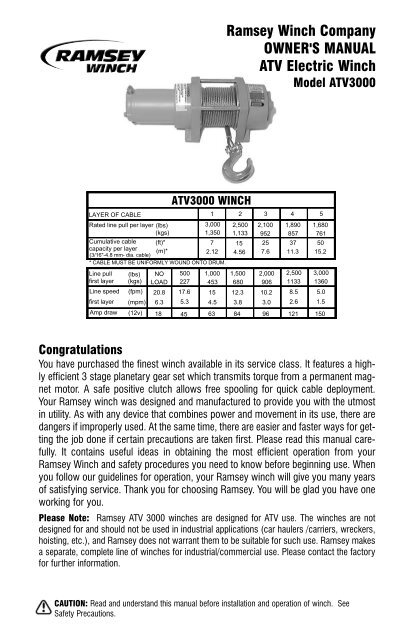
Ramsey Winch Company OWNER'S MANUAL ATV Electric Winch
Ramsey Winch Company OWNER'S MANUAL ATV Electric Winch
Ramsey Winch Company OWNER'S MANUAL ATV Electric Winch

Create successful ePaper yourself
Turn your PDF publications into a flip-book with our unique Google optimized e-Paper software.
LAYER OF CABLE<br />
<strong>ATV</strong>3000 WINCH<br />
Rated line pull per layer (lbs)<br />
3,000 2,500<br />
(kgs)<br />
1,350 1,133<br />
Cumulative cable<br />
capacity per layer<br />
(3/16"-4.8 mm- dia. cable)<br />
(ft)*<br />
(m)*<br />
7<br />
2.12<br />
15<br />
4.56<br />
* CABLE MUST BE UNIFORMLY WOUND ONTO DRUM.<br />
Line pull (lbs) NO 500 1,000 1,500<br />
first layer (kgs) LOAD 227 453 680<br />
Line speed (fpm) 20.8 17.6 15 12.3<br />
first layer (mpm) 6.3 5.3 4.5 3.8<br />
Amp draw (12v) 18 45 63 84<br />
1<br />
<strong>Ramsey</strong> <strong>Winch</strong> <strong>Company</strong><br />
<strong>OWNER'S</strong> <strong>MANUAL</strong><br />
<strong>ATV</strong> <strong>Electric</strong> <strong>Winch</strong><br />
Model <strong>ATV</strong>3000<br />
2 3<br />
2,100<br />
952<br />
25<br />
7.6<br />
2,000<br />
906<br />
10.2<br />
3.0<br />
96<br />
4 5<br />
1,890<br />
857<br />
37<br />
11.3<br />
2,500<br />
1133<br />
8.5<br />
2.6<br />
121<br />
1,680<br />
761<br />
50<br />
15.2<br />
3,000<br />
1360<br />
5.0<br />
1.5<br />
150<br />
Congratulations<br />
You have purchased the finest winch available in its service class. It features a highly<br />
efficient 3 stage planetary gear set which transmits torque from a permanent magnet<br />
motor. A safe positive clutch allows free spooling for quick cable deployment.<br />
Your <strong>Ramsey</strong> winch was designed and manufactured to provide you with the utmost<br />
in utility. As with any device that combines power and movement in its use, there are<br />
dangers if improperly used. At the same time, there are easier and faster ways for getting<br />
the job done if certain precautions are taken first. Please read this manual carefully.<br />
It contains useful ideas in obtaining the most efficient operation from your<br />
<strong>Ramsey</strong> <strong>Winch</strong> and safety procedures you need to know before beginning use. When<br />
you follow our guidelines for operation, your <strong>Ramsey</strong> winch will give you many years<br />
of satisfying service. Thank you for choosing <strong>Ramsey</strong>. You will be glad you have one<br />
working for you.<br />
Please Note: <strong>Ramsey</strong> <strong>ATV</strong> 3000 winches are designed for <strong>ATV</strong> use. The winches are not<br />
designed for and should not be used in industrial applications (car haulers /carriers, wreckers,<br />
hoisting, etc.), and <strong>Ramsey</strong> does not warrant them to be suitable for such use. <strong>Ramsey</strong> makes<br />
a separate, complete line of winches for industrial/commercial use. Please contact the factory<br />
for further information.<br />
CAUTION: Read and understand this manual before installation and operation of winch. See<br />
Safety Precautions.
Contents<br />
Performance Specifications . . . . . . . . . .cover<br />
Safety Precautions . . . . . . . . . . . . . . . . . . . .2<br />
Tips for Safe Operation . . . . . . . . . . . . . . . .2<br />
Techniques of Operation . . . . . . . . . . . . . . .3<br />
General Installation . . . . . . . . . . . . . . . . . . .3<br />
Rotating the Motor . . . . . . . . . . . . . . . . . .4-7<br />
Operating Instructions . . . . . . . . . . . . . . . . .8<br />
Maintenance . . . . . . . . . . . . . . . . . . . . . . . .8<br />
Cable Installation . . . . . . . . . . . . . . . . . . . . .8<br />
Wireless Remote Control Operation . . . . . . .8<br />
Trouble Shooting Guide . . . . . . . . . . . . . . . .9<br />
<strong>Winch</strong> Parts List (Wireless Remote) . . .10-11<br />
<strong>Electric</strong>al Schematic (Wireless Remote) . . .11<br />
Rocker Switch Operation . . . . . . . . . . . . . .12<br />
Rocker Switch Installation . . . . . . . . . .12-14<br />
<strong>Electric</strong>al Schematic (Rocker Switch) . . . .13<br />
<strong>Winch</strong> Parts List (Rocker Switch) . . . . .14-15<br />
Warranty . . . . . . . . . . . . . . . . . . .back cover<br />
Safety Precautions To Guard<br />
Against Possible Injury.....<br />
A. Keep yourself and others a safe distance to<br />
the side of the cable when pulling under load.<br />
B. Do not step over a cable, or near a cable<br />
under load.<br />
C. Use supplied hook strap when handling hook<br />
for spooling wire rope.<br />
D. Do not use the <strong>ATV</strong> to pull a load on the<br />
winch cable. This could result in cable breakage<br />
and/or winch damage<br />
E. Use a heavy rag or gloves to protect hands<br />
from burrs when handling winch cable.<br />
F. Apply blocks to wheels when <strong>ATV</strong> is on an<br />
incline.<br />
G. <strong>Winch</strong> clutch should be disengaged when<br />
winch is not in use and fully engaged when in<br />
use.<br />
H. Modification, alteration, or deviation to the<br />
winch should only be made by <strong>Ramsey</strong><br />
<strong>Winch</strong> <strong>Company</strong>.<br />
2<br />
I. Keep the duration of your pulls as short as<br />
possible. If the motor becomes uncomfortably<br />
hot to the touch, stop and let it cool for a<br />
few minutes. Do not pull more than one<br />
minute at or near the rated load. Do not<br />
maintain power to the winch if the motor<br />
stalls. <strong>Electric</strong> winches are for intermittent<br />
usage and should not be used in constant<br />
duty applications.<br />
J. Do not use winch in hoisting applications due<br />
to required hoist safety factors and features.<br />
K. Do not exceed maximum line pull ratings<br />
shown in tables. Shock loads must not<br />
exceed these ratings.<br />
L. To respool correctly, it is necessary to keep a<br />
slight load on the cable. Do not allow the<br />
cable to slip through your hand and do not<br />
approach the winch too closely. When all the<br />
cable except a few feet is in, stop and finish<br />
spooling in cable by rotating the drum by<br />
hand with clutch disengaged. Always use<br />
hook strap to hold hook when spooling.<br />
Tips for Safe Operation<br />
Don't underestimate the potential danger in<br />
winching operations. Neither should you fear<br />
them. Do learn the basic dangers and avoid<br />
them.<br />
Observe spooling of cable onto drum. Side pulls<br />
can cause cable to pileup at one end of the drum.<br />
To correct uneven stacking, spool out that section<br />
of the cable and move it to the other end of the<br />
drum and continue winching. Uneven spooling<br />
which causes cable pileup can interfere with the<br />
winch tie rods causing damage to the winch.<br />
Store the wireless remote control transmitter in a<br />
safe place where it will not become damaged.<br />
Inspect it before you use it.<br />
When ready to begin winching, push and hold the<br />
On/Off button on the transmitter until it flashes.<br />
Do not engage clutch with motor running.<br />
Never connect the hook back to the cable. This
causes cable damage. Always use a sling or<br />
chain of suitable strength.<br />
Observe your winch while winching. If possible,<br />
while standing at a safe distance. If you use <strong>ATV</strong><br />
drive to assist, stop and get off every few feet to<br />
assure the cable is not piling up in one corner.<br />
Jamming cable can break your winch.<br />
Do not attach tow hooks to winch mounting apparatus.<br />
They must attach to <strong>ATV</strong> frame.<br />
When double lining during stationary winching,<br />
the winch hook should be attached to the chassis<br />
of the <strong>ATV</strong>. Since the greatest pulling power is<br />
achieved on the innermost layer of your winch, it<br />
is desirable to pull off as much line as you can for<br />
heavy pulls. If this is not practical, use a snatch<br />
block and double line arrangement.<br />
Neat, tight spooling avoids cable binding which is<br />
caused when a load is applied and the cable is<br />
pinched between two other wraps of cable. If this<br />
happens, alternately power the winch in and out a<br />
few inches. Do not attempt to work a bound<br />
cable under load, free by hand.<br />
Techniques of Operation<br />
The best way to get acquainted with how your<br />
winch operates is to make a few test runs before<br />
you actually need to use it. Plan your test in<br />
advance. Remember you hear your winch as well<br />
as see it operate. Get to recognize the sound of a<br />
light steady pull, a heavy pull, and sounds caused<br />
by load jerking or shifting. Soon you will gain<br />
confidence in operating your winch and its use<br />
will become second nature with you.<br />
Your winch will not only pull your <strong>ATV</strong> up or ease<br />
your <strong>ATV</strong> down a steep grade, it will also pull<br />
another <strong>ATV</strong> or a load while your <strong>ATV</strong> is anchored<br />
in a stationary position.<br />
When pulling a heavy load, place a blanket, jacket<br />
or tarpaulin over the cable five or six feet from the<br />
For basic self-recovery, anchor to a tree or heavy rock.<br />
When anchoring to a tree, always use a tree trunk protector.<br />
3<br />
hook. It will slow the snap back in the event of a<br />
broken cable.<br />
Use the <strong>ATV</strong> wheel power to help the winch, but<br />
don't overtake the winch line. Plan your pull.<br />
You can't always hook up and pull out in one step.<br />
Examine all the areas for anchoring possibilities<br />
as well as leverage situations, direction, and goal.<br />
<strong>Winch</strong>es equipped with cable guide fairleads can pull<br />
from several directions. Pull from an angle only to<br />
straighten up the <strong>ATV</strong>-otherwise you can damage structural<br />
members or other parts of your <strong>ATV</strong> and cause<br />
excess cable buildup on one end of the winch drum.<br />
General Installation<br />
The winch shown in this owner’s manual is solely<br />
and exclusively designed for <strong>ATV</strong> mounted, nonindustrial<br />
applications. All other applications will<br />
void warranty.<br />
1. Install <strong>Winch</strong> and Mounting Kit according to<br />
instructions supplied with Mounting Kit.<br />
Tighten mounting bolts to 16 ft-lbs torque.<br />
2. It is very important that the winch be<br />
mounted on a flat surface, with the cable<br />
feeding from the bottom of the drum.<br />
CAUTION: SUPPLIED 7/8” LONG MOUNTING BOLTS WITH LOCK-<br />
WASHERS ARE FOR A RECOMMENDED WINCH MOUNTING PLATE<br />
THICKNESS OF 3/16”. IF A DIFFERENT MOUNTING PLATE THICKNESS<br />
IS USED, THE BOLT LENGTH MUST BE ADJUSTED ACCORDINGLY OR<br />
DAMAGE TO WINCH MAY OCCUR. REPLACEMENT BOLTS MUST BE<br />
SAE GRADE 5 OR EQUIVALENT.<br />
3. Do not attach motor and battery leads until<br />
instructed to do so.<br />
4. Refer to installation instructions for the<br />
Wireless Remote Switch (in the <strong>ATV</strong> Wireless<br />
Installation and Operation Manual) for installation<br />
of the switch and electrical assemblies for<br />
the winch.
Rotating the Motor on your <strong>ATV</strong><br />
<strong>Winch</strong><br />
The <strong>ATV</strong> winch has the motor studs and leads<br />
positioned on the end of the motor aligned vertically.<br />
If you need to rotate the motor on your <strong>ATV</strong><br />
winch to gain clearance, you can rotate the motor<br />
90°. The motor studs will then be aligned horizontally.<br />
Before you begin:<br />
Note: If you have installed the optional Brake kit<br />
(P/N 256116) for the <strong>ATV</strong> winch, make sure you<br />
have the Brake kit installation instructions before<br />
proceeding. You will need to re-install the Brake<br />
kit after you rotate the motor (step 6 on the following<br />
pages). Contact <strong>Ramsey</strong> if you do not<br />
have your installation instructions.<br />
1. Remove the cable from the drum. Turn the<br />
clutch handle to Freespool and pull cable off.<br />
Slide the end of the cable out of the pocket<br />
next to the drum flange until the cable anchor<br />
can be removed. Be sure to keep the cable<br />
anchor for re-installing the cable. Leave the<br />
clutch set to Freespool.<br />
2. Disconnect the motor leads.<br />
3. Remove the winch from its mounting channel.<br />
Place it on a sturdy, level workbench.<br />
Set the winch down on the clutch end.<br />
1. Remove the tie bar bolts and nuts. Pull tie bars<br />
from between end bearings.<br />
2. Lift the motor end off the drum and set down<br />
with the motor end down. Make sure the shaft,<br />
drum bushing and spring stay with the drum.<br />
4
3. Remove the bolts that hold the end plate to the<br />
motor end housing. Lift off the end plate and<br />
take the nuts and washers out of the mounting<br />
feet. Set aside the gear assemblies and bushing.<br />
The input sun and planetary gear carrier<br />
may come out together.<br />
4. Lean the motor end and loosen the motor tie<br />
bolts off the tie bolt nuts. Lean the motor end<br />
back up so that it is sitting upright. Do not let<br />
the motor end cap come apart from the<br />
rest of the motor. Lift the motor end housing<br />
and rotate 90°. Put the tie bolt nuts in the other<br />
set of pockets and carefully lean the motor end<br />
back. Tighten the tie bolts to 45-50 in-lbs.<br />
torque. Do not overtighten.<br />
5. After rotating the motor, the motor end will<br />
appear as shown at right. The motor studs will<br />
be aligned horizontally, and the motor tie bolt<br />
nuts will be in the other set of pockets.<br />
5
6. Replace the gears into the motor end housing,<br />
fitting the input sun gear over the motor shaft.<br />
The planetary gear carrier should be seated so<br />
that the bushing, as shown at lower right, is<br />
flush with the ring gear.<br />
7. Re-install the end plate on the housing with<br />
the bolts you removed earlier. Tighten these<br />
bolts to 45-50 in-lbs. torque. Do not overtighten.<br />
8. Lift the motor end assembly onto the drum.<br />
Turn the drum and motor end assembly so<br />
that the shaft fits into the input sun gear.<br />
Lean the motor end assembly slightly to one<br />
side to insert the tie bars into their holes.<br />
9. Slide the tie bar bolts through the tie bars and<br />
into their nuts. Tighten the tie bar bolts to 45-<br />
50 in-lbs. torque. Do not over tighten. The finished<br />
winch should look as shown below,<br />
with the motor studs aligned horizontally.<br />
Confirm that the drum freespools properly without<br />
binding.<br />
Refer to the winch mounting kit installation<br />
instructions for re-installing the winch. Re-install<br />
the winch cable according to the instructions in<br />
this manual.<br />
6<br />
Insert the mounting nuts and washers into the<br />
pockets of the housing as shown. Make sure they<br />
do not fall out while re-installing the end plate.
NOTES<br />
7
Operating Instructions<br />
The winch clutch allows rapid unspooling of the wire<br />
rope for hooking onto the load or anchor point. The<br />
clutch is operated by the shifter located on the end of<br />
the winch as follows:<br />
1. To disengage the clutch, turn the clutch shifter to<br />
the "FREESPOOL" position. Wire rope may now be<br />
freespooled off the drum.<br />
2. To engage the clutch, turn the clutch shifter to the<br />
"ENGAGED" position. The winch is now ready for<br />
pulling.<br />
Your battery must be kept in good condition. A fully<br />
charged battery and proper connections are essential.<br />
Run the <strong>ATV</strong> engine during winching operations to keep<br />
battery charged.<br />
Maintenance<br />
Corrosion on electrical connections will reduce performance<br />
or may cause a short. Clean all connections.<br />
In salty environments use a silicone sealer to protect<br />
from corrosion.<br />
To minimize corrosion of the internal motor components<br />
that may occur due to condensation, power the wench<br />
in or out periodically. Energizing the motor will generate<br />
heat, which will help dissipate any moisture buildup in<br />
the motor. This should be performed at periodic intervals<br />
(such as with each oil change of your vehicle).<br />
Note: Refer to Troubleshooting Guide if the motor has<br />
been submerged.<br />
See supplied instructions for programming a replacement<br />
transmitter.<br />
All moving parts in the winch are permanently lubricated<br />
with broad temperature range lithium based grease.<br />
Lubricate cable periodically using light penetrating oil.<br />
Inspect for broken strands and replace if necessary. If<br />
the cable becomes worn or damaged, it must be<br />
replaced.<br />
Cable Installation<br />
Note: Cable should be installed so that it feeds<br />
from the bottom of the drum.<br />
8<br />
Unwind the new cable by rolling it out along the ground<br />
to prevent kinking. Remove old cable and observe the<br />
manner in which it is attached to the cable drum flange,<br />
watching carefully for the cable anchor puck.<br />
Before installing the new cable assembly, securely wrap<br />
the end of the cable with tape to prevent fraying.<br />
The short end of the cable should<br />
extend approximately 1/8” beyond<br />
the top edge of pocket.<br />
Slide the cable through narrow end of the pocket<br />
against drum flange and wrap the cable around the<br />
anchor puck. Pull the cable and anchor back into the<br />
wide end of the pocket leaving approximately 1/8”<br />
beyond edge of pocket as shown. Use a hammer and<br />
drift punch to drive the back side of the wire rope, firmly<br />
seating the wire rope and anchor into the pocket.<br />
Wind on the cable by pulling in a light load to keep the<br />
tension constant. Allow the cable to swivel by using a<br />
length of chain or a swivel block between the cable<br />
hook and the load.<br />
Wireless Remote Control Operation<br />
Caution: When the transmitter reaches a temperature<br />
below 0°F (-18°C) it will not operate.<br />
In extremely cold temperatures, keep transmitter<br />
in a pocket of innermost layer of clothing<br />
when not in use.<br />
The transmitter has push buttons labeled according to<br />
their function. Make sure the motor has stopped fully<br />
before reversing to prevent premature solenoid failure.<br />
To operate the winch hold “ON/OFF” button for 2 seconds<br />
to activate the “IN and “OUT” functions. Run<br />
winch forward and reverse to check connection and to<br />
verify winch operating directions. The transmitter is<br />
clearly labeled and a red LED flashes when the winch is<br />
in operation. Pushing both buttons at the same time<br />
will not damage your winch in any way. Press and hold<br />
the “ON/OFF” button on the transmitter to disable the<br />
transmitter when winch is not in use. This will prolong<br />
the battery life of the transmitter. The transmitter automatically<br />
turns off after 20<br />
minutes.<br />
Refer to page 5 of<br />
Remote Control<br />
Installation Instructions<br />
for remote operation<br />
notes.
<strong>ATV</strong>3000 Trouble Shooting Guide<br />
CONDITIONS POSSIBLE CAUSE CORRECTION<br />
MOTOR RUNS IN ONLY ONE Defective solenoid or stuck solenoid. Jar solenoid assembly to free contacts. Check each<br />
DIRECTION solenoid by applying +12 volts to coil terminal (it<br />
should make an audible click when energized).<br />
Defective remote control Check winch operation with auxilliary<br />
or low battery in transmitter. toggle switch.<br />
Check battery in transmitter.<br />
Defective Rocker Switch Replace Rocker Switch<br />
MOTOR RUNS EXTREMELY Long period of operation Cooling-off periods are essential to<br />
HOT prevent overheating.<br />
MOTOR RUNS, BUT WITH Insufficient battery Test for faulty vehicle battery.<br />
INSUFFICIENT POWER<br />
OR WITH LOW LINE SPEED Bad connection Check battery cable for corrosion;<br />
clean and grease<br />
Insufficient charging system Replace with larger capacity charging<br />
system.<br />
MOTOR RUNS, BUT DRUM Clutch not engaged If clutch engaged but symptoms still<br />
DOES NOT TURN exist, it will be necessary to disassem<br />
ble winch to determine cause and<br />
repair.<br />
MOTOR WILL NOT OPERATE Defective solenoid or stuck solenoid. Jar solenoid assembly to free contacts.<br />
Check solenoid by applying 12 volts to<br />
coil terminal (it should make an audible<br />
click when energized).<br />
Defective remote control Check winch operation with auxilliary<br />
or low battery in transmitter. toggle switch.<br />
Check transmitter battery.<br />
Defective Rocker Switch. Replace Rocker Switch.<br />
Defective motor If solenoids operate, check for voltage<br />
at armature post; replace motor.<br />
Loose connections. Check all electrical connections from<br />
the battery to the motor.<br />
MOTOR WATER DAMAGED Submerged in water or water Allow to drain and dry thoroughly, then<br />
from high pressure car wash Run motor without a load in short<br />
bursts to dry windings.<br />
WINCH RUNS IN OPPOSITE Motor leads crossed. Reverse electrical connections to<br />
DIRECTION OF TRANSMITTER motor.<br />
BUTTONS<br />
Solenoid control wires Reverse position of green and yellow<br />
crossed. wires on solenoid assembly.<br />
9
RAMSEY <strong>ATV</strong>3000 (Wireless Remote)<br />
1<br />
10<br />
13<br />
5<br />
10<br />
9<br />
4<br />
16-<br />
Hardware<br />
Kit<br />
4 5<br />
3<br />
7<br />
2<br />
11<br />
9<br />
6 8<br />
1<br />
2<br />
14<br />
*Hardware Kit<br />
Item No. Qty. Description<br />
16-1 4 5/16-18UNC x 1” Hx Hd<br />
Z/P GR5 Capscrew<br />
16-2 2 3/8-16UNC x 3/4” Hx Hd<br />
Z/P GR5 Capscrew<br />
16-3 2 #10-24UNC x 3/4” Truss<br />
Cross-recess F/B Capscrew<br />
16-4 2 3/8-16UNC Hx GR2 Z/P Nut<br />
16-5 2 #10-24UNC Hx Locknut<br />
16-6 4 5/16 Med Z/P Lockwasher<br />
16-7 2 3/8 Med Z/P Lockwasher<br />
16-8 2 #10 Flat Washer Z/P<br />
16-9 1 Wire Splice<br />
16-10 2 Tube Clamp<br />
16-11 1 pkg Cable Ties<br />
10<br />
12<br />
6<br />
11<br />
3<br />
15<br />
7<br />
8
<strong>Winch</strong> Parts List <strong>ATV</strong>3000 (Wireless Remote)<br />
ITEM<br />
NO.<br />
1<br />
2<br />
3<br />
4<br />
5<br />
6<br />
7<br />
8<br />
9<br />
10<br />
11<br />
12<br />
13<br />
14<br />
15<br />
16<br />
QTY.<br />
1<br />
1<br />
1<br />
1<br />
1<br />
1<br />
1<br />
1<br />
1<br />
1<br />
1<br />
1<br />
1<br />
1<br />
1<br />
1<br />
PART<br />
NO.<br />
251214<br />
251189<br />
251191<br />
251192<br />
251193<br />
251194<br />
251236<br />
251195<br />
251196<br />
251197<br />
282058<br />
251190<br />
251234<br />
251235<br />
251198<br />
257522<br />
DESCRIPTION<br />
<strong>Electric</strong>al Schematic (Wireless Remote)<br />
FEMALE SPADE<br />
CONNECTOR<br />
BLACK MOTOR<br />
LEAD<br />
TOGGLE SWITCH<br />
MALE SPADE<br />
CONNECTOR<br />
TRANSMITTER<br />
ON/OFF<br />
YELLOW WIRE<br />
#2<br />
RED WIRE<br />
WIRE SPLICE<br />
IN<br />
OUT<br />
RED WIRE W/<br />
WHITE STRIPE TO<br />
ACCESSORY WIRE<br />
ON VEHICLE IGNI-<br />
TION<br />
GREEN WIRE<br />
MOTOR<br />
BLACK<br />
BATTERY LEAD<br />
#1<br />
WIRELESS<br />
SIGNAL<br />
GREEN WIRE<br />
YELLOW<br />
WIRE<br />
MOTOR KIT<br />
MOTOR END GEAR SET<br />
CLUTCH KIT<br />
CABLE DRUM KIT<br />
CABLE & HOOK KIT<br />
CLUTCH END GEAR KIT<br />
ROLLER FAIRLEAD (ON CERTAIN MODELS)<br />
BUSHING KIT<br />
TIE BAR KIT<br />
ELECTRICAL WIRING KIT<br />
WIRELESS RECEIVER & TRANSMITTER KIT<br />
WIRELESS TRANSMITTER<br />
SOLENOID KIT<br />
TOGGLE SWITCH<br />
ANTENNA KIT<br />
HARDWARE KIT*<br />
RECEIVER<br />
Programing instructions: Press and hold membrane below,<br />
press ON/OFF button on transmitter for 3 seconds ,<br />
press OUT button for 3 seconds or until winch activation .<br />
11<br />
PUSH<br />
Tulsa . Oklahoma, . USA<br />
(918)438-2760 . FAX(918)438-6688<br />
WWW.RAMSEY.COM<br />
WIRING<br />
HARNESS<br />
SOLENOID ASS’Y.<br />
GREEN WIRE<br />
YELLOW WIRE<br />
RED<br />
BATTERY LEAD<br />
BLACK WIRE<br />
TO GROUND<br />
BLACK W/<br />
YELLOW STRIPE<br />
MOTOR LEAD<br />
BATTERY<br />
ANTENNA<br />
COAX CABLE<br />
NOTE:<br />
TORQUE SOLENOID<br />
TERMINAL NUTS TO<br />
35-40 IN-LBS.
Rocker Switch Operation<br />
Press Rocker Switch toward “IN” position to spool<br />
cable “IN” and press Rocker Switch toward “OUT”<br />
position to spool cable “OUT”.<br />
Rocker Switch Installation<br />
The Rocker Switch will mount to the handle bars<br />
of the <strong>ATV</strong>.<br />
Before Beginning Installation<br />
1. Install mounting kit and winch according to<br />
the mounting kit instructions.<br />
2. Disconnect negative (-) battery cable<br />
from battery. Turn off vehicle ignition.<br />
3. Disengage winch clutch.<br />
4. Remove hood or cowling as necessary for<br />
easier access to installation area.<br />
5. Locate and mark mounting location for<br />
Solenoid Assembly.<br />
6. Locate accessory wire from vehicle ignition<br />
switch that is powered only when ignition is<br />
ON. Use this wire when splicing to Red wire<br />
on Rocker switch.<br />
7. Make sure locations are close enough for<br />
wiring connections to be made without making<br />
alterations to wire lengths.<br />
CAUTION: DO NOT CONNECT NEGATIVE BATTERY CABLE<br />
OR ENGAGE CLUTCH UNTIL INSTALLATION IS COMPLETE.<br />
WINCH COULD BEGIN SPOOLING CABLE UNEXPECTEDLY<br />
CAUSING INJURY OR DAMAGE TO WINCH.<br />
Note: For certain mounting applications, where<br />
the solenoid needs to be mounted at the rear of<br />
the vehicle, switch the battery and motor leads.<br />
This will allow the longer leads to reach the<br />
winch at the front of the vehicle.<br />
Solenoid Mounting: Choose a mounting location<br />
that will remain protected and dry. Solenoid<br />
should be mounted on a flat surface.<br />
12<br />
Installing the Solenoid<br />
1. Use Solenoid Assembly as a guide to mark<br />
and drill (2) 7/32” holes in location determined<br />
for solenoid.<br />
2. Use (2) 3/4” long #10 capscrews (item<br />
#14-3), (2) #10 flat washers (item #14-8),<br />
and (2) #10 locknuts (item #14-5) to mount<br />
solenoid. Tighten to 60 in-lbs (7 Nm) torque.<br />
Installing the Rocker Switch<br />
For clarification, see wiring schematic on page 9.<br />
1. Position Tube Clamp (item #14-12) on handle<br />
bars in convenient location.<br />
2. Mount Rocker Switch housing to Tube Clamp<br />
using #10 capscrew, locknut, flat washer,<br />
and shake-proof washer (items #14-3, #14-<br />
5, #14-8, and #14-9). Tighten securely.<br />
3. Push the Green, Red, and Yellow wires<br />
through the back of the switch housing.
<strong>Electric</strong>al Schematic (Rocker Switch)<br />
BLACK MOTOR<br />
LEAD<br />
#2<br />
IN<br />
OUT<br />
MOTOR<br />
ROCKER SWITCH<br />
#1<br />
GREEN WIRE<br />
SOLENOID ASS’Y.<br />
BLACK W/ YELLOW<br />
STRIPE MOTOR<br />
LEAD<br />
BLACK<br />
BATTERY LEAD<br />
4. Install the Gasket onto the Rocker Switch.<br />
5. Connect Yellow wire (item #12-3) to top terminal<br />
on Rocker Switch (terminal behind “IN”<br />
position). Connect Red wire (item #12-1) to<br />
middle terminal on Rocker switch. Connect<br />
Green wire (item #12-2) into bottom terminal<br />
of Rocker switch.<br />
6. Slide Green, Yellow, and Red wires into loom<br />
(item #12-4). Slide loom up to back of the<br />
switch housing.<br />
7. Snap switch and switch housing together.<br />
8. Push Accessory wire from ignition and other<br />
end of Red wire into plastic Splice.<br />
C<br />
E<br />
RED WIRE<br />
13<br />
A<br />
B<br />
YELLOW WIRE<br />
RED<br />
BATTERY LEAD<br />
SPLICE<br />
TO <strong>ATV</strong> IGNITION<br />
BATTERY<br />
NOTE:<br />
TORQUE SOLENOID<br />
TERMINAL NUTS TO<br />
35-40 IN-LBS.<br />
For certain mounting applications, where the solenoid needs to<br />
be mounted at the rear of the vehicle, switch the battery and<br />
motor leads. In this case, connect the black w/yellow stripe<br />
lead to the positive (+) terminal of the battery, and the longer<br />
black lead to the negative (-) terminal. Connect the red lead<br />
and the shorter black lead to the motor terminals.<br />
9. Fold splice clip over itself and snap closed.<br />
10. Route wires from Rocker Switch down the<br />
handle bars. Turn the handle bars fully right<br />
and left to ensure plenty of clearance.<br />
11. Make sure wires are not drawn taut across<br />
any surfaces that could damage them. Use<br />
cable ties to anchor wires. Tie off excess.<br />
Connect Wiring to Solenoid (unless motor and<br />
battery leads are switched)<br />
CAUTION: TIGHTEN NUTS ON TERMINAL STUDS TO 35-40<br />
IN-LBS. (3-4 NM) TORQUE. DO NOT OVER-TIGHTEN.<br />
1. Connect Red Battery Lead (Item #13-2)<br />
between “A” terminal on Solenoid and positive<br />
(+) vehicle battery terminal.<br />
2. Connect Black Motor Lead (item #13-4)<br />
between #2 terminal on motor and C terminal<br />
on solenoid. Connect Black w/Yellow<br />
Stripe Motor Lead (item #13-1) between #1<br />
terminal on motor and B terminal on solenoid.<br />
3. Connect Black Battery Lead (item #13-3) to<br />
“E” terminal on Solenoid and route to negative<br />
(-) vehicle battery terminal but do not<br />
connect.
4. Plug Yellow wire from switch into right terminal<br />
(terminal above black with yellow stripe<br />
motor lead). Plug Green wire from switch into<br />
left terminal (terminal above black motor<br />
lead).<br />
Finish Installation<br />
1. Confirm that winch clutch is disengaged.<br />
2. Connect negative (-) battery cable to vehicle<br />
battery. Connect Black Battery Lead from<br />
winch to negative (-) vehicle battery terminal.<br />
3. With ignition switch OFF, press Rocker switch<br />
to “OUT”—winch should not operate. If the<br />
<strong>ATV</strong>3000 (Rocker Switch) Parts List<br />
ITEM<br />
NO.<br />
1<br />
2<br />
3<br />
4<br />
5<br />
6<br />
7<br />
8<br />
9<br />
10<br />
11<br />
12<br />
13<br />
14<br />
QTY.<br />
1<br />
1<br />
1<br />
1<br />
1<br />
1<br />
1<br />
1<br />
1<br />
1<br />
1<br />
1<br />
1<br />
1<br />
PART<br />
NO.<br />
251214<br />
251189<br />
251191<br />
251192<br />
251193<br />
251213<br />
251236<br />
251195<br />
251196<br />
251234<br />
257536<br />
299728<br />
299724<br />
257535<br />
DESCRIPTION<br />
1. Switch Wiring Kit, as shown on facing page,<br />
consists of the following components:<br />
ITEM NO. QTY. DESCRIPTION<br />
12-1 1 123” RED WIRE<br />
12-2 1 123” GREEN WIRE<br />
12-3 1 123” YELLOW WIRE<br />
12-4 1 24” LOOM<br />
14<br />
winch does operate with the ignition off, confirm<br />
that proper accessory wire from ignition<br />
was spliced.<br />
4. Spool a few feet of cable out by hand. Engage<br />
winch clutch. Turn ignition switch ON and<br />
press Rocker switch to “OUT”—winch should<br />
spool cable out.<br />
6. If winch does not operate with ignition on,<br />
check wiring to the schematic on page 14.<br />
7. If winch spools cable IN instead of OUT, turn<br />
off ignition and reverse yellow and green<br />
wires on solenoid.<br />
MOTOR KIT<br />
MOTOR END GEAR SET KIT<br />
CLUTCH KIT<br />
CABLE DRUM KIT<br />
CABLE & HOOK KIT<br />
CLUTCH END GEAR KIT<br />
ROLLER FAIRLEAD KIT<br />
BUSHING KIT<br />
TIE BAR KIT<br />
SOLENOID KIT<br />
ROCKER SWITCH KIT<br />
SWITCH WIRING KIT 1<br />
SOLENOID WIRING KIT 2<br />
HARDWARE KIT 3<br />
2. Solenoid Wiring Kit, as shown on facing<br />
page, consists of the following components:<br />
ITEM NO. QTY. DESCRIPTION<br />
13-1 1 37” MOTOR LEAD - BLACK<br />
W/YELLOW STRIPE<br />
13-2 1 97” BATTERY LEAD - RED<br />
13-3 1 97” BATTERY LEAD - BLACK<br />
13-4 1 37” MOTOR LEAD - BLACK
<strong>ATV</strong>3000 (Rocker Switch)<br />
1<br />
13<br />
4 5<br />
9<br />
2<br />
10<br />
3. Hardware Kit consists of the following components:<br />
ITEM NO. QTY. DESCRIPTION<br />
14-1 4 5/16-18UNC X 1” LG HX HD Z/P<br />
CAPSCREW<br />
14-2 2 3/8-16UNC X 1” LG HX HD GR5<br />
Z/P CAPSCREW<br />
14-3 3 #10-24NC X 3/4 LG TR CROSS<br />
RECESS F/B CAPSCREW<br />
14-4 2 3/8-16UNC REG HX HD GR2<br />
Z/P NUT<br />
14-5 3 #10-24NC HEX LOCK NUT<br />
14-6 4 5/16” MED Z/P LOCK WASHER<br />
14-7 2 3/8” MED Z/P LOCK WASHER<br />
14-8 3 #10 Z/P FLAT WASHER<br />
14-9 1 #10 SHAKE-PROOF WASHER<br />
14-10 1 WIRE SPLICE<br />
14-11 1 PKG CABLE TIES (12 EA)<br />
14-12 1 TUBE CLAMP<br />
15<br />
6<br />
12<br />
5<br />
12<br />
10<br />
4<br />
14-<br />
Hardware<br />
Kit<br />
3<br />
7<br />
3<br />
2<br />
11<br />
6 8<br />
11<br />
1<br />
9<br />
7<br />
8
Warranty Information<br />
<strong>Ramsey</strong> <strong>Winch</strong>es are designed and built to exacting specifications. Care and skill go into every winch we make.<br />
If the need should arise, warranty procedure is outlined on the back of your self-addressed, postage paid warranty<br />
card. Please read and fill out the enclosed warranty card and send it to <strong>Ramsey</strong> <strong>Winch</strong> <strong>Company</strong>. If you<br />
have any problems with your winch, please follow instructions for prompt service on all warranty claims.<br />
Limited Lifetime Warranty<br />
<strong>Ramsey</strong> <strong>Winch</strong> offers a limited lifetime warranty for each new <strong>Ramsey</strong> <strong>ATV</strong> winch against manufacturing defects in workmanship and materials on all<br />
manufactured components.<br />
Warranty registration cards for each winch must be submitted at the time of purchase, or within 90 days. Online registration of your winch is available<br />
at www.ramsey.com.<br />
New cable assemblies are warranted against defects in workmanship and materials. No warranty applies after initial use.<br />
All <strong>Ramsey</strong> mounting kits and other accessories carry a 1- year limited warranty against defects in materials and workmanship.<br />
This warranty is void if winch is used in industrial applications.<br />
<strong>Electric</strong>al components consisting of motors, solenoids, wiring, wire connectors, and associated parts carry a limited 1-year warranty.<br />
The obligation under this warranty, statutory or otherwise, is limited to the replacement or repair at the manufacturers factory, or at a point designated by<br />
the manufacturer, of such part as shall appear to the manufacturer, upon inspection of such part, to have been defective in material or workmanship. This<br />
Warranty does not obligate <strong>Ramsey</strong> <strong>Winch</strong> <strong>Company</strong> to bear the cost of transportation charges in connection with the replacement or repair of defective<br />
parts, nor shall it apply to a product upon which repairs or alterations have been made, unless authorized by the manufacturer, or for equipment misused,<br />
neglected, or improperly installed.<br />
Important notice: To the fullest extent permitted by applicable law, the following are hereby excluded and disclaimed: 1. All warranties of<br />
fitness for a particular purpose; 2. All warranties of merchantability; 3. All claims for consequential or incidental damages. There are no<br />
warranties that extend beyond the description that appears on the face hereof.<br />
Some states do not allow the above exclusions or disclaimers in consumer transactions and as such this disclaimer/exclusion may not apply<br />
to your particular case.<br />
To the extent such warranties of fitness for a particular purpose or merchantability are deemed to apply to this product, they exist only for<br />
so long as the express limited warranty elsewhere set forth is in existence.<br />
<strong>Ramsey</strong> <strong>Winch</strong> <strong>Company</strong> makes no warranty in respect to accessories, same being subject to the warranties of their respective manufacturers.<br />
<strong>Ramsey</strong> <strong>Winch</strong> <strong>Company</strong>, whose policy is one of continuous product improvement, reserves the right to improve any product through changes in design<br />
or materials as it may deem desirablewithout being obligated to incorporate such changes in products of previous manufacture.<br />
If field service at the request of the buyer is rendered and the fault is found not to be with <strong>Ramsey</strong> <strong>Winch</strong> <strong>Company</strong>’s product, the buyer shall pay the<br />
time and expense of the field representative. Bills for service, labor or other expenses which have been incurred by the buyer without express approval or<br />
authorization by <strong>Ramsey</strong> <strong>Winch</strong> <strong>Company</strong> will not be accepted.<br />
This Warranty gives you specific legal rights and you may also have other legal rights which vary from state to state.<br />
RAMSEY WINCH COMPANY<br />
P.O. BOX 581510 TULSA, OKLAHOMA 74158-1510 USA PHONE: (918) 438-2760 FAX: (918) 438-6888<br />
http://www.ramsey.com<br />
OM-914053-0105-R
INSTALLATION AND OPERATING<br />
INSTRUCTIONS FOR RAMSEY<br />
WIRELESS REMOTE CONTROL<br />
FOR THE <strong>ATV</strong> WINCH<br />
The following are general installation instructions. Actual<br />
installation may vary depending on the <strong>ATV</strong> manufacturer<br />
and model.<br />
Warnings<br />
1. THE RAMSEY WIRELESS REMOTE FOR THE <strong>ATV</strong> WINCH IS DESIGNED<br />
FOR USE ON SELF-RECOVERY WINCHES ONLY. THE REMOTE IS NOT<br />
DESIGNED FOR AND SHOULD NOT BE USED ON WINCHES OR HOISTS IN<br />
INDUSTRIAL APPLICATIONS (CAR HAULERS/CARRIERS, WRECKERS,<br />
CRANES, ETC.) OR FOR ANY OTHER REMOTE CONTROLLED APPLICATION.<br />
2. WHEN REELING IN CABLE UNDER NO LOAD, RELEASE THE REMOTE BUT-<br />
TON WHEN THE HOOK IS A MINIMUM OF 3 FT (1 M) FROM THE WINCH<br />
FAIRLEAD. CAREFULLY JOG THE REMOTE CONTROL BUTTON UNTIL THE<br />
HOOK IS A MINIMUM OF 1 FT (.3M) FROM THE FAIRLEAD. DISENGAGE<br />
THE CLUTCH AND FINISH SPOOLING IN CABLE BY ROTATING THE DRUM BY<br />
HAND.<br />
3. When finished winching, turn transmitter off.<br />
4. Do not pressure wash or steam clean the receiver. This can<br />
damage the receiver and adversely affect operation.<br />
5. Refer to winch owner’s manual for all winch operating instructions<br />
and warnings.
NOTES
Contents<br />
Parts List .........................................................1<br />
Before Beginning Installation ............................2<br />
Installation .......................................................2-4<br />
<strong>Electric</strong>al Schematic ........................................5<br />
Testing & Operation .........................................6<br />
Troubleshooting Guide......................................7
ITEM<br />
NO.<br />
1<br />
2<br />
3<br />
4<br />
5<br />
6<br />
7<br />
8<br />
9<br />
10<br />
11<br />
12<br />
13<br />
QTY.<br />
1<br />
1<br />
1<br />
1<br />
1<br />
2<br />
2<br />
2<br />
1<br />
1<br />
2<br />
1<br />
1<br />
PART<br />
NO.<br />
282058<br />
251198<br />
251234<br />
251190<br />
*<br />
416227<br />
418140<br />
440125<br />
251235<br />
440274<br />
251197<br />
* SONY CR2032 OR DURACELL DL2032<br />
REMOTE<br />
TRANSMITTER<br />
TOGGLE SWITCH<br />
REMOTE RECEIVER<br />
1<br />
DESCRIPTION<br />
WIRELESS RECEIVER & TRANSMITTER KIT<br />
DIPOLE ANTENNA KIT<br />
SOLENOID KIT<br />
REPLACEMENT TRANSMITTER<br />
REPLACEMENT BATTERY<br />
SCREW #10-24 X 3/4 TRUSS F/B<br />
NUT #10-24 HEX LOCK<br />
FLAT WASHER #10 Z/P<br />
WIRE SPLICE<br />
TOGGLE SWITCH<br />
TUBE CLAMP<br />
CABLE TIES<br />
WIRE KIT<br />
ANTENNA<br />
WIRE KIT<br />
SOLENOID<br />
TUBE CLAMP<br />
MOUNTING<br />
SCREWS<br />
CABLE TIE<br />
WIRE SPLICE<br />
LOCK NUTS<br />
FLATWASHERS
Before Beginning Installation<br />
1. Disconnect power lead from winch to battery.<br />
2. Disengage winch clutch.<br />
3. Remove hood or cowling as necessary for easier access to installation<br />
area.<br />
4. Locate & mark mounting locations for receiver, toggle switch, solenoid<br />
assembly, & antenna.<br />
NOTE: Make sure locations are close enough for wiring connections to<br />
be made without making alterations to wire lengths. Solenoid assembly<br />
will be mounted to tube frame of <strong>ATV</strong> using supplied tube clamps,<br />
except Polaris models which mount directly to the <strong>ATV</strong> cross member<br />
under hood using supplied mounting screws.<br />
For certain mounting applications, where the solenoid needs to be<br />
mounted at the rear of the vehicle, switch the battery and motor leads.<br />
This will allow the longer leads to reach the winch at the front of the<br />
vehicle.<br />
The antenna will need a space of at least 15” wide under cowling or<br />
hood for mounting in the horizontal configuration required for best<br />
reception. Antenna is flexible and will follow the contour of the cowling<br />
or hood. The antenna should be mounted at least 10” from winch motor<br />
and battery leads.<br />
Installing the Receiver<br />
1. Insert plastic tie through mounting ears on receiver and secure receiver to<br />
location determined above.<br />
2. Tighten plastic tie and clip excess.<br />
3. Attach ground wire to <strong>ATV</strong> frame.<br />
CAUTION: DO NOT ALTER THE LENGTH OF THE GROUND WIRE AS<br />
THIS WILL AFFECT PERFORMANCE OF THE REMOTE.<br />
4. Attach wiring harness to receiver & route yellow and green wires to solenoid<br />
location.<br />
Installing the Motor Leads (unless motor and battery leads are switched)<br />
1. Connect black wire to #2 stud on motor.<br />
2. Connect black with yellow stripe wire to #1 stud.<br />
3. Route wires to solenoid location.<br />
2
Connecting Wiring to Solenoid (unless motor and battery leads are<br />
switched)<br />
NOTE: For clarification see wiring schematic on page 5.<br />
1. Attach black with yellow stripe motor lead to lower right terminal stud<br />
“B” on solenoid.<br />
2. Attach black motor lead to lower left terminal stud “C” on solenoid .<br />
3. Attach connector with 2 yellow wires to the terminal directly above the<br />
black with yellow stripe motor lead.<br />
4. Attach connector with 2 green wires to the terminal directly above the<br />
black motor lead.<br />
5. Attach black battery lead to upper left terminal stud “E” on solenoid.<br />
6. Attach red battery lead to upper right terminal stud “A” on solenoid.<br />
Installing the Solenoid<br />
1. Mount solenoid in location determined previously.<br />
2. Secure using (1) tube clamp, (1) #10-24 screw, (1) flat washer,<br />
and (1) lock nut each side of solenoid assembly.<br />
CAUTION: BE SURE THAT NO WIRE CONNECTIONS ARE IN<br />
CONTACT WITH EITHER THE <strong>ATV</strong> FRAME OR WITH EACH<br />
OTHER AS A DIRECT SHORT WILL OCCUR.<br />
Installing the Toggle Switch<br />
1. Route red, yellow and green wires to toggle switch location.<br />
2. Drill 1/2” hole in location for toggle switch installation.<br />
3. Insert switch through hole drilled in previous step.<br />
4. Place directional plate over switch and secure using knurled nut.<br />
Using wrench, tighten backup nut securely against inside of instrument<br />
cover. Make sure directional plate is installed in the same<br />
direction as the toggle switch movement.<br />
5. Place rubber boot over switch and tighten securely.<br />
3
Wiring the Toggle Switch<br />
NOTE: For clarification see wiring schematic on page 5.<br />
1. Connect red wire to center spade.<br />
2. Connect green wire to the toggle switch terminal in the “OUT”<br />
position.<br />
3. Connect the yellow wire to the toggle switch terminal in the “IN”<br />
position.<br />
Connecting the Power Lead<br />
1. Locate accessory wire from <strong>ATV</strong> ignition.<br />
NOTE: <strong>ATV</strong> accessory wire should have 12 volts only when<br />
ignition key is on. Receiver should only have power when vehicle<br />
ignition is ON.<br />
2. Connect red wire with white stripe to accessory wire. Use supplied<br />
quick splice connector if needed.<br />
Installing the Antenna<br />
NOTE: For clarification see wiring schematic on page 5.<br />
1. Clean predetermined mounting surface with Isopropyl alcohol and<br />
buff dry. (In <strong>ATV</strong>s without hoods the best place to mount the<br />
antenna will be the underside of the <strong>ATV</strong> cowling in the highest<br />
possible position.)<br />
2. Remove backing from top side of double-stick tape and apply to<br />
back side of pc board. Remove backing from other side of double-stick<br />
tape and position pc board in center on top inside surface<br />
of cowling or hood at the predetermined mounting location.<br />
3. Remove backing from copper tape. Carefully affix tape to terminal<br />
on right side of pc board and follow contour of inside of cowling.<br />
DO NOT ALTER LENGTH OF THE TAPE. Repeat for left side.<br />
4. Route coax cable up from receiver to antenna and plug in at pc<br />
board.<br />
4
<strong>Electric</strong>al Schematic<br />
FEMALE SPADE<br />
CONNECTOR<br />
MALE SPADE<br />
CONNECTOR<br />
TRANSMITTER<br />
TOGGLE SWITCH<br />
WIRE<br />
SPLICE<br />
BLACK MOTOR<br />
LEAD<br />
#2<br />
OUT<br />
IN<br />
YELLOW WIRE<br />
RED WIRE<br />
RED WIRE W/<br />
WHITE STRIPE TO<br />
ACCESSORY WIRE<br />
ON VEHICLE IGNI-<br />
TION<br />
MOTOR<br />
GREEN WIRE<br />
WIRELESS<br />
SIGNAL<br />
GREEN WIRE<br />
YELLOW<br />
WIRE<br />
SOLENOID ASS’Y.<br />
BLACK W/ YELLOW<br />
STRIPE MOTOR<br />
LEAD<br />
#1<br />
C<br />
E<br />
RECEIVER<br />
Programing instructions: Press and hold membrane below,<br />
press ON/OFF button on transmitter for 3 seconds ,<br />
press OUT button for 3 seconds or until winch activation .<br />
Tulsa . Oklahoma, . USA<br />
(918)438-2760 . FAX(918)438-6688<br />
WWW.RAMSEY.COM<br />
5<br />
A<br />
PUSH<br />
BLACK<br />
BATTERY LEAD<br />
B<br />
GREEN WIRE<br />
YELLOW WIRE<br />
RED<br />
BATTERY LEAD<br />
ANTENNA<br />
BLACK WIRE<br />
TO GROUND<br />
WIRING HARNESS<br />
NOTE:<br />
TORQUE SOLENOID<br />
TERMINAL NUTS TO<br />
35-40 IN-LBS.<br />
BATTERY<br />
COAX CABLE<br />
For certain mounting applications, where the solenoid needs to<br />
be mounted at the rear of the vehicle, switch the battery and<br />
motor leads. In this case, connect the black w/yellow stripe<br />
lead to the positive (+) terminal of the battery, and the longer<br />
black lead to the negative (-) terminal. Connect the red lead<br />
and the shorter black lead to the motor terminals.
Testing/Operation<br />
LED<br />
1. Reconnect the positive power lead from IN<br />
OUT<br />
solenoid to battery.<br />
2. Pull approximately 20 ft of cable off the<br />
winch by hand.<br />
ON/OFF<br />
3. Re-engage the winch clutch.<br />
4. Test the remote transmitter. The transmitter<br />
has push buttons labeled accord-<br />
Transmitter<br />
ing to their function. To operate the<br />
winch, hold “ON/OFF” button for 2 seconds to activate the “IN” and “OUT”<br />
functions. (1 flash indicates transmitter is “ON”, 2 flashes indicate transmitter<br />
is “OFF”).<br />
6. Run winch in the “OUT” direction briefly. Make sure the motor has stopped<br />
fully before reversing to prevent premature solenoid failure. Run winch in the<br />
“IN” direction briefly.<br />
7. Follow instructions in your winch owner’s manual for properly reeling in the<br />
rest of the cable. The transmitter is clearly labeled and a red LED flashes<br />
when the winch is in operation. To turn transmitter off, press and hold the<br />
“ON/OFF” button for 2 seconds to disable the transmitter when winch is not<br />
in use. This will prolong the battery life of the transmitter. The transmitter<br />
automatically turns off after 20 minutes.<br />
PROGRAMMING THE RECEIVER FOR USE WITH A REPLACEMENT TRANSMITTER<br />
When you purchase a replacement transmitter, it will be necessary to program<br />
your receiver to accept the code for the new transmitter. To program the receiver,<br />
press and hold membrane located in the center of receiver face (area marked<br />
“push”). Press and hold “ON/OFF” button on transmitter for 3 seconds. Press<br />
and hold “OUT” button for 3 seconds or until winch activates.<br />
CAUTION: The center membrane area of the receiver face must only be pressed<br />
when programming a new transmitter.<br />
6
Trouble Shooting Guide<br />
Condition<br />
Transmitter won’t<br />
operate<br />
Remote receiver will not<br />
operate.<br />
Intermittent operation.<br />
Possible Cause<br />
Transmitter is off.<br />
Low transmitter battery<br />
voltage.<br />
Transmitter temperature<br />
below 0°F (-18°C).<br />
Bad ground connection.<br />
Receiver not coded with<br />
transmitter.<br />
Antenna mounted too<br />
close to winch motor and<br />
battery leads.<br />
External environmental<br />
conditions causing intermittent<br />
operation in a<br />
specific transmitter location.<br />
Signal deflecting off of<br />
land mass or solid<br />
structures.<br />
Transmitter out of operating<br />
range.<br />
Operating within 50 ft. of<br />
any similar device.<br />
Low <strong>ATV</strong> battery voltage.<br />
7<br />
Correction<br />
Turn transmitter on (See<br />
Testing/Operation) .<br />
Replace Battery.<br />
In extremely cold temperatures,<br />
keep transmitter in a<br />
pocket of innermost layer<br />
of clothing when not in<br />
use.<br />
Make sure receiver ground<br />
wire has good connection<br />
to <strong>ATV</strong> ground.<br />
Program receiver (refer to<br />
Programming the<br />
Receiver).<br />
Mount antenna at least 10<br />
inches from winch motor<br />
and battery leads.<br />
Move the transmitter<br />
around the <strong>ATV</strong> until normal<br />
operation resumes .<br />
Keep transmitter in direct<br />
line of sight with antenna<br />
for optimal operation.<br />
Stay within 50 ft. of antenna<br />
for optimal operation.<br />
Make sure no similar<br />
devices are within 50 ft. of<br />
vehicle.<br />
Make sure <strong>ATV</strong> battery<br />
voltage is above 9.5 volts.
NOTES
Warranty Information<br />
If the need should arise, warranty procedure is outlined on the back of your self-addressed, postage paid warranty<br />
card. Please read and fill out the enclosed warranty card and send it to <strong>Ramsey</strong> <strong>Winch</strong> <strong>Company</strong>. If you have any<br />
problems with your wireless remote, please follow instructions for prompt service on all warranty claims.<br />
Limited Lifetime Warranty<br />
<strong>Ramsey</strong> <strong>Winch</strong> offers a limited lifetime warranty for each new <strong>Ramsey</strong> wireless remote against manufacturing defects in workmanship<br />
and materials on all manufactured components.<br />
The wireless remote carries a limited 1-year warranty.<br />
The obligation under this warranty, statutory or otherwise, is limited to the replacement or repair at the manufacturers factory, or at a<br />
point designated by the manufacturer, of such part as shall appear to the manufacturer, upon inspection of such part, to have been<br />
defective in material or workmanship. This Warranty does not obligate <strong>Ramsey</strong> <strong>Winch</strong> <strong>Company</strong> to bear the cost of transportation<br />
charges in connection with the replacement or repair of defective parts, nor shall it apply to a product upon which repairs or alterations<br />
have been made, unless authorized by the manufacturer, or for equipment misused, neglected, or improperly installed.<br />
Important notice: To the fullest extent permitted by applicable law, the following are hereby excluded and disclaimed: 1.<br />
All warranties of fitness for a particular purpose; 2. All warranties of merchantability; 3. All claims for consequential or<br />
incidental damages. There are no warranties that extend beyond the description that appears on the face hereof.<br />
Some states do not allow the above exclusions or disclaimers in consumer transactions and as such this disclaimer/exclusion<br />
may not apply to your particular case.<br />
To the extent such warranties of fitness for a particular purpose or merchantability are deemed to apply to this product,<br />
they exist only for so long as the express limited warranty elsewhere set forth is in existence.<br />
<strong>Ramsey</strong> <strong>Winch</strong> <strong>Company</strong> makes no warranty in respect to accessories, same being subject to the warranties of their respective manufacturers.<br />
<strong>Ramsey</strong> <strong>Winch</strong> <strong>Company</strong>, whose policy is one of continuous product improvement, reserves the right to improve any product through<br />
changes in design or materials as it may deem desirable without being obligated to incorporate such changes in products of previous<br />
manufacture.<br />
If field service at the request of the buyer is rendered and the fault is found not to be with <strong>Ramsey</strong> <strong>Winch</strong> <strong>Company</strong>’s product, the buyer<br />
shall pay the time and expense of the field representative. Bills for service, labor or other expenses which have been incurred by the<br />
buyer without express approval or authorization by <strong>Ramsey</strong> <strong>Winch</strong> <strong>Company</strong> will not be accepted.<br />
This Warranty gives you specific legal rights and you may also have other legal rights which vary from state to state.<br />
RAMSEY WINCH COMPANY<br />
P.O. BOX 581510 TULSA, OKLAHOMA 74158-1510 USA PHONE: (918) 438-2760 FAX: (918) 438-6888<br />
http://www.ramsey.com<br />
OM-914062-0106-H