EM-101-BI MOTOR CONTROLLER 24V 4A 4-QUAD - Electromen
EM-101-BI MOTOR CONTROLLER 24V 4A 4-QUAD - Electromen
EM-101-BI MOTOR CONTROLLER 24V 4A 4-QUAD - Electromen
- No tags were found...

You also want an ePaper? Increase the reach of your titles
YUMPU automatically turns print PDFs into web optimized ePapers that Google loves.
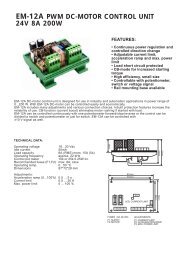
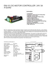
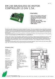
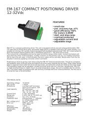
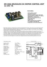
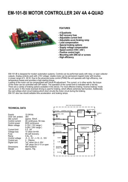
<strong>EM</strong>-<strong>101</strong>-<strong>BI</strong> <strong>MOTOR</strong> <strong>CONTROLLER</strong> <strong>24V</strong> <strong>4A</strong> 4-<strong>QUAD</strong>FEATURES- 4 Quadrants- Self recovery fuse- Adjustable current limit- Adjustable accel./braking ramp- Load compensation- Special braking options- Supply voltage compensation- Speed control ±10V ( ±5V )- Positive control logic- Mounting with DIN-rail or screws- High efficiency<strong>EM</strong>-<strong>101</strong>-<strong>BI</strong> is designed for modern automation systems. Controls can be performed easily with relay- or open collectoroutputs. Analog controls work with ±10V voltage. Usable motor can be permanent magnet motor with brushesin power range of 5...80 W. Due to the advanced pulse control (PWM) the unit operates with high efficiency, lowtemperature losses and provides a high starting torque.Loading of the motor can be compensated with inbuilt RI-adjustment. The current, or in other words, the torqueof the motor can be controlled with DIP-switch. The operation of the current limit is indicated with a red led.There are a variety of braking options available in this device. For most effective braking “reverse braking”-modecan be used. In this mode reversed driving is used for braking, which effects extremely fast function. Additionallythe card utilises short circuit braking which short circuits the motor circuit during the braking.<strong>EM</strong>-<strong>101</strong> also has inbuild settable time acceleration- and braking ramps.TECHNICAL DATASupplyOver volt. protect.Idle currentControl currentControl powerMotor voltageCurrent limitVoltage lossFuseRampControl voltageControl pot.Digital cont.DimensionsWeight12-34Vdc36Vapprox. 50mA<strong>4A</strong> continuous, 5A max.80W continuous0-15V ( 12V range )0-29V ( <strong>24V</strong> range )0.3...5A1V when Im=<strong>4A</strong><strong>4A</strong> self recovery.0,5s...5s-5...0...5V -->-10...0...10V2...10kohm"on" when Uin 4 -30V"off" when Uin 0-1V or open89x73x26mmapprox. 70g957865V 5mACONTROL GND-5V 5mASPEED SETSPEED SCALERUN/STOPRAMP.I-LIM.REVERSEBRAKE TIME<strong>EM</strong>-<strong>101</strong>-<strong>BI</strong> BLOCK DIAGRAMCONTROL VOLTAGE-5VCONTROLLOGICPOWERREGUL.POWER STAGEH-BRIDGE12V / <strong>24V</strong>VOLTAG<strong>EM</strong>EAS.CURRENTMEAS.<strong>4A</strong> PTC FUSE+-1SUPPLYIN23-<strong>MOTOR</strong>+4IR-KOMP.
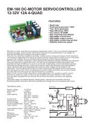
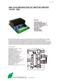
OPERATING INSTRUCTIONS <strong>EM</strong>-<strong>101</strong>-<strong>BI</strong>Supply voltage must be DC with ripple less than 20%. Supplyvoltage 12...34V. In the beginning set all trimmers as shownin lay-out picture. Choose 12 / 24 according to the supply used.1 2+ -3-4+NOTE! When reversed braking is used the controller will takea very high current peak. Capacitor for the power supplyshould be at least 4700uF at 1A.CrPOWERSOURC<strong>EM</strong>OTOR89mmONP3ONOFF1 2 3 41 2 3OFFCONNECTORS73mmFUSET<strong>4A</strong>VOLTAGE RANGE12VCURRENTRAMPLIMITREVERSE BRAKINGTIME<strong>24V</strong>P2SPEED-1 /P1POT. RANGECOMPENSATIONRxI66mm1. Supply 12-34Vdc2. Supply GND 0V3. Motor (-)4. Motor (+)5. Control GND 0V6. Run / ( Stop )7. -5V Aux. voltage out ( 5mA )8. Reference voltage in9. +5 Reference out ( 5mA)1 2 3 4 5 6 7 8 982mmonCURRENT LIMITLimitation of the current ( torque )Controlled with DIP-switches.12340A0.3A0.6A1A1.3A1.6A1.9A2.2A12342.5A2.8A3.2A3.5A3.9A4.2A4.6A5.0AonTHE RAMP & BRAKINGIn the map below the first two ramp settings are specialbraking options. The first position is so called reversebraking; the motor is controlled in opposite direction.Reverse braking time is set with trim P3. braking where themotor circuit is short circuited during the braking. Otherpositions are for normal acceleration and braking settingswhich are set with DIP-switches.123Reverse braking, no rampShort circuit braking, no ramp0,5s. ramp1s. rampREVERSE BRAKING2s. rampTIME TRIM3s. ramp4s. ramp5s. rampmin. 3msP3max. 256ms
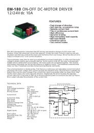
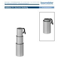
COMPENSATIONWith compensation you can compensate the loadeffect to motor rpm. This feature increases controllingif current increases in the motor circuit. The needfor compensation depends on application and motor.Typically small motors require more compensationthan big ones. Over compensation occurs as twichingof the motor.CONTROLLINGThe max value of controlling voltage ranges ±( 5...10V ). Thefull range is thus maintained on 0...5V. The range can beset with trim P1.P2increase compensationP10%50%min.max.100%range -5..0..5V (-100...0...100%)range -10..0..10V (-100...0...100%)<strong>EM</strong>-<strong>101</strong> CONNECTION EXAMPLESOne direction drive.Speed adjustment withpotentiometer.Two direction drive.Speed and direction controlwith potentiometer.Two direction drive with voltage signal.Run continuous on.56 7 8 9 10567 8 95 67 8 9SPEEDRUNSPEEDRUNUcont.CONTROL VOLTAGE -5..0..5 or -10..0..-10VTwo direction drive with switch.Run continuous on.Two direction drive with switch.Speed with external potentiometer.Run continuous on.Two direction drive with voltage signal,run with voltage control.567 8 95 67 8 95 67 8 9REWIND FORWARDSPEEDREWINDFORWARDRUN WHENUk > 4VUkUcont.CONTROL VOLTAGE -5..0..5 or -10..0..-10VELECTROMEN OyVähäheikkiläntie 56B, 20810 Turku, FINLAND Tel. +358-2-4693050 Fax. +358-2-4693052