Si3217x Si3291x
Si3217x Si3291x
Si3217x Si3291x
- No tags were found...

You also want an ePaper? Increase the reach of your titles
YUMPU automatically turns print PDFs into web optimized ePapers that Google loves.
<strong>Si3217x</strong><strong>Si3291x</strong>2 Rev. 1.1
<strong>Si3217x</strong> <strong>Si3291x</strong>TABLE OF CONTENTSSectionPage1. Electrical Specifications . . . . . . . . . . . . . . . . . . . . . . . . . . . . . . . . . . . . . . . . . . . . . . . . . . .52. Schematics . . . . . . . . . . . . . . . . . . . . . . . . . . . . . . . . . . . . . . . . . . . . . . . . . . . . . . . . . . . . .263. Bill of Materials . . . . . . . . . . . . . . . . . . . . . . . . . . . . . . . . . . . . . . . . . . . . . . . . . . . . . . . . . .314. Overview . . . . . . . . . . . . . . . . . . . . . . . . . . . . . . . . . . . . . . . . . . . . . . . . . . . . . . . . . . . . . . .365. FXS Features . . . . . . . . . . . . . . . . . . . . . . . . . . . . . . . . . . . . . . . . . . . . . . . . . . . . . . . . . . .365.1. DC Feed Characteristics . . . . . . . . . . . . . . . . . . . . . . . . . . . . . . . . . . . . . . . . . . . . . .365.2. Linefeed Operating States . . . . . . . . . . . . . . . . . . . . . . . . . . . . . . . . . . . . . . . . . . . .365.3. Line Voltage and Current Monitoring . . . . . . . . . . . . . . . . . . . . . . . . . . . . . . . . . . . .365.4. Power Monitoring and Power Fault Detection . . . . . . . . . . . . . . . . . . . . . . . . . . . . . .375.5. Thermal Overload Shutdown . . . . . . . . . . . . . . . . . . . . . . . . . . . . . . . . . . . . . . . . . .375.6. Loop Closure Detection . . . . . . . . . . . . . . . . . . . . . . . . . . . . . . . . . . . . . . . . . . . . . . .385.7. Ground Key Detection . . . . . . . . . . . . . . . . . . . . . . . . . . . . . . . . . . . . . . . . . . . . . . . .385.8. Ringing Generation . . . . . . . . . . . . . . . . . . . . . . . . . . . . . . . . . . . . . . . . . . . . . . . . . .385.9. Polarity Reversal . . . . . . . . . . . . . . . . . . . . . . . . . . . . . . . . . . . . . . . . . . . . . . . . . . . .385.10. Two-Wire Impedance Synthesis . . . . . . . . . . . . . . . . . . . . . . . . . . . . . . . . . . . . . . .385.11. Transhybrid Balance Filter . . . . . . . . . . . . . . . . . . . . . . . . . . . . . . . . . . . . . . . . . . .385.12. Tone Generators . . . . . . . . . . . . . . . . . . . . . . . . . . . . . . . . . . . . . . . . . . . . . . . . . . .385.13. DTMF Detection . . . . . . . . . . . . . . . . . . . . . . . . . . . . . . . . . . . . . . . . . . . . . . . . . . .395.14. Pulse Metering (Si32171 Only) . . . . . . . . . . . . . . . . . . . . . . . . . . . . . . . . . . . . . . . .395.15. DC-DC Controller . . . . . . . . . . . . . . . . . . . . . . . . . . . . . . . . . . . . . . . . . . . . . . . . . .395.16. Wideband Audio . . . . . . . . . . . . . . . . . . . . . . . . . . . . . . . . . . . . . . . . . . . . . . . . . . .395.17. In-Circuit and Metallic Loop Testing (MLT) . . . . . . . . . . . . . . . . . . . . . . . . . . . . . .396. FXO Features . . . . . . . . . . . . . . . . . . . . . . . . . . . . . . . . . . . . . . . . . . . . . . . . . . . . . . . . . . .416.1. Isolation Barrier . . . . . . . . . . . . . . . . . . . . . . . . . . . . . . . . . . . . . . . . . . . . . . . . . . . . .416.2. Power Management . . . . . . . . . . . . . . . . . . . . . . . . . . . . . . . . . . . . . . . . . . . . . . . . .416.3. In-Circuit Testing . . . . . . . . . . . . . . . . . . . . . . . . . . . . . . . . . . . . . . . . . . . . . . . . . . . .416.4. Transmit/Receive Full-Scale Level . . . . . . . . . . . . . . . . . . . . . . . . . . . . . . . . . . . . . .416.5. Line Voltage Measurement . . . . . . . . . . . . . . . . . . . . . . . . . . . . . . . . . . . . . . . . . . . .416.6. Loop Current Measurement . . . . . . . . . . . . . . . . . . . . . . . . . . . . . . . . . . . . . . . . . . .416.7. Parallel Handset Detection . . . . . . . . . . . . . . . . . . . . . . . . . . . . . . . . . . . . . . . . . . . .416.8. DC Termination . . . . . . . . . . . . . . . . . . . . . . . . . . . . . . . . . . . . . . . . . . . . . . . . . . . . .416.9. AC Termination . . . . . . . . . . . . . . . . . . . . . . . . . . . . . . . . . . . . . . . . . . . . . . . . . . . . .426.10. Ring Detection . . . . . . . . . . . . . . . . . . . . . . . . . . . . . . . . . . . . . . . . . . . . . . . . . . . . .426.11. Ring Validation . . . . . . . . . . . . . . . . . . . . . . . . . . . . . . . . . . . . . . . . . . . . . . . . . . . .426.12. Ringer Impedance and Threshold . . . . . . . . . . . . . . . . . . . . . . . . . . . . . . . . . . . . . .426.13. Pulse Dialing and Spark Quenching . . . . . . . . . . . . . . . . . . . . . . . . . . . . . . . . . . . .426.14. Receive Overload Detection . . . . . . . . . . . . . . . . . . . . . . . . . . . . . . . . . . . . . . . . . .436.15. On-Hook Line Monitor . . . . . . . . . . . . . . . . . . . . . . . . . . . . . . . . . . . . . . . . . . . . . . .436.16. Transhybrid Balance . . . . . . . . . . . . . . . . . . . . . . . . . . . . . . . . . . . . . . . . . . . . . . . .437. System Interfaces . . . . . . . . . . . . . . . . . . . . . . . . . . . . . . . . . . . . . . . . . . . . . . . . . . . . . . . .437.1. SPI Control Interface . . . . . . . . . . . . . . . . . . . . . . . . . . . . . . . . . . . . . . . . . . . . . . . . .433 Rev. 1.1
<strong>Si3217x</strong><strong>Si3291x</strong>1. Electrical SpecificationsTable 1. Absolute Maximum Ratings and Thermal Information 1Parameter Symbol Test Condition Value UnitStorage Temperature Range T STG — –55 to 150 °CThermal Resistance, Typical 2QFN-42 JA — 32 °C/WContinuous Power Dissipation 3,4QFN-42P D T A =85°C 1.3 WMaximum Junction Temperature,QFN-42 (Linefeed Die)T JHV Continuous 145 °CMaximum Junction TemperatureQFN-42 (Low Voltage Die)T JLV — 125 °CThermal Resistance, Typical 2SOIC-16 JA — 85 °C/WContinuous Power Dissipation 3SOIC-16P D T A =85°C 0.47 WMaximum Junction TemperatureSOIC-16T J — 125 °C<strong>Si3217x</strong>Supply VoltageV DDD, V DDA,V DDHV— –0.5 to 4.0 VDigital Input Voltage V IND — –0.3 to 3.6 VBattery Supply Voltage 5 , Si32171/6/8 V BAT — +0.4 to –115 VBattery Supply Voltage 5 , Si32177 V BAT — +0.4 to –140 VTip or Ring Voltage, Si32171/6/8 6 V TIP , V RING — –130 VTip or Ring Voltage, Si32177 6 V TIP , V RING — –140 VTIP, RING Current I TIP , I RING — ±100 mA<strong>Si3291x</strong>Notes:1. Permanent device damage may occur if the absolute maximum ratings are exceeded. Functional operation should berestricted to the conditions as specified in the operational sections of this data sheet.2. The thermal resistance of an exposed pad package is assured when the recommended printed circuit board layoutguidelines are followed correctly. The specified performance requires that the exposed pad be soldered to an exposedcopper surface of at least equal size and that multiple vias are added to enable heat transfer between the top-sidecopper surface and a large internal/bottom copper plane.3. Operation of the <strong>Si3217x</strong> or <strong>Si3291x</strong> above 125 °C junction temperature may degrade device reliability.4. <strong>Si3217x</strong> linefeed is equipped with on-chip thermal limiting circuitry that shuts down the circuit when the junctiontemperature exceeds the thermal shutdown threshold. The thermal shutdown threshold should normally be set to 145°C; when in the ringing state with cadence the thermal shutdown may be set to 200 °C. For optimal reliability long termoperation of the <strong>Si3217x</strong> linefeed above 150 °C junction temperature should be avoided.5. The dv/dt of the voltage applied to the VBAT pins must be limited to 10 V/µs.6. Specification requires circuit for surge event as shown in typical application circuit.Rev. 1.1 5
<strong>Si3217x</strong><strong>Si3291x</strong>Table 2. Recommended Operating Conditions 1Parameter Symbol TestConditionMin* Typ Max* UnitF-grade 0 25 70 °CAmbient Temperature T AG-grade –40 25 85 °CSilicon Junction Temperature,QFN-42T JHV Linefeed Die — — 145 °CSupply Voltage, <strong>Si3217x</strong> V DDD , V DDA ,3.13 3.3 3.47 VV DDHVBattery Voltage, Si32171/6/8 2 V BAT –110 –95 –15 VBattery Voltage, Si32177 2 V BAT –136 –130 –15 VNotes:1. All minimum and maximum specifications apply across the recommended operating conditions. Typical values apply atnominal supply voltages and an operating temperature of 25 ° C unless otherwise stated.2. Operation at minimum voltage dependent upon loop conditions and dc-dc converter configuration.Table 3. Power Supply Characteristics for <strong>Si3217x</strong>(V DD =3.3V, T A = 0 to 70 ºC)Parameter Symbol Test Condition Min Typ Max UnitSupply Currents:ResetSupply Currents:High Impedance, OpenSupply Currents:Forward/Reverse, On-hookSupply Currents:Forward/Reverse, On-hookSupply Currents:Tip/Ring Open, On-hookI DD — 9.7 — mAI VBATVT and VR = Hi-Z , RST = 0— 0.0 — mAI DD— 13.2 — mAVT and VR = Hi-Z, FXO disabledI VBAT — 0.47 — mAI DD VTR = –48 V, FXO disabled, — 11.2 — mAAutomatic Power Save ModeI VBAT enabled— 0.44 — mAI DD VTR = –48 V, FXO disabled, — 27.2 — mAAutomatic Power Save ModeI VBAT disabled— 1.4 — mAI DD VT or VR = –48 V VR or VT = Hi- — 12.5 — mAZ, FXO disabled, AutomaticI VBAT Power Save Mode enabled — 0.4 — mANotes:1. I LOOP is the dc current in the subscriber loop during the off-hook state.2. I AVE is the average of the full-wave rectified current in the subscriber loop during ringing (IAVE = IPEAK x 2/π) = 36 mAunder test conditions shown for ringing current3. RGDT is not functional in this state.4. I DD =I DDD +I DDA +I DDC .5. Refer to AN340 for power supply consumption of the recommended applications circuit, including dc-dc converter.6 Rev. 1.1
<strong>Si3217x</strong><strong>Si3291x</strong>Table 3. Power Supply Characteristics for <strong>Si3217x</strong> (Continued)(V DD =3.3V, T A = 0 to 70 ºC)Parameter Symbol Test Condition Min Typ Max UnitSupply Currents:Tip/Ring Open, On-hookSupply Currents:Forward/Reverse OHT, OnhookSupply Currents:Forward/Reverse Active, OffhookSupply Currents:RingingSystem Side FXO SupplyCurrentSystem Side FXO SupplyCurrentSystem Side FXO SupplyCurrentSystem Side FXO SupplyCurrentI DD VT or VR = –48 V VR or VT = Hi- — 26.3 — mAZ, FXO disabled, AutomaticI VBATPower Save Mode disabled— 0.95 — mAI DD— 40.6 — mAVTR =48 V, FXO disabledI VBAT — 2.3 — mAI DD ILOOP = 30 mA RLOAD = 50 Ω,— 40.9 — mAI VBATFXO disabled— 2.0 — mAI DDVTR =55V RMS + 0 VDC, balanced,FXO disabledsinusoidal, f = 20 Hz, RLOAD = 5I VBAT —REN = 1400 Ω— 28 — mA2.0 +I AVE2 — mAI DD FXO enabled — 10.0 — mAI DD FXO enabled, FXO in Sleep Mode — 6.3 — mAI DDFXO enabled, FXO in Full PowerDown Mode 3 — 0.1 — mAI DD FXO disabled — — 0 mANotes:1. I LOOP is the dc current in the subscriber loop during the off-hook state.2. I AVE is the average of the full-wave rectified current in the subscriber loop during ringing (IAVE = IPEAK x 2/π) = 36 mAunder test conditions shown for ringing current3. RGDT is not functional in this state.4. I DD =I DDD +I DDA +I DDC .5. Refer to AN340 for power supply consumption of the recommended applications circuit, including dc-dc converter.Rev. 1.1 7
<strong>Si3217x</strong><strong>Si3291x</strong>Table 4. AC Characteristics for FXS(V DD = 3.13 to 3.47 V, T A = 0 to 70 °C)Parameter Test Condition Min Typ Max UnitTX/RX PerformanceOverload Level 2.5 — — V PKOverload Compression 2-Wire – PCM Figure 15 — —Single Frequency Distortion 1 2-Wire – PCM or PCM – 2-Wire: +35 40 — dB200Hz to 3.4kHzPCM – 2-Wire – PCM:— — –63 dB200 Hz – 3.4 kHz,16-bit Linear modeSignal-to-(Noise + Distortion)200Hz to 3.4kHz Figure 14 — —Active off-hook, and OHT, any Z TRatio 2D/A or A/D 8-bitAudio Tone Generator Signal-to- 0 dBm0, Active off-hook, and 46 — — dBDistortion Ratio 2OHT, any Z TIntermodulation Distortion — — –41 dBGain Accuracy 22-Wire to PCM or PCM to 2-Wire1014 Hz, Any gain setting–0.2 — 0.2 dBAttenuation Distortion vs. Freq. 0 dBm 0 See Figure 16 and 17Group Delay vs. Frequency See Figure 18 and 19Gain Tracking 31014 Hz sine wave,— — — —reference level –10 dBmSignal level:3 dB to –37 dB — — 0.25 dB–37 dB to –50 dB — — 0.5 dB–50 dB to –60 dB — — 1.0 dBRound-Trip Group Delay 1014 Hz, Within same time-slot — 450 500 µs2-Wire Return Loss 4 200Hz to 3.4kHz 26 30 — dBTranshybrid Balance 4 300Hz to 3.4kHz 26 30 — dBNoise PerformanceIdle Channel Noise 5 C-Message weighted — 8 12 dBrnCPsophometric weighted — –82 –78 dBmPPSRR from V DDD , V DDA ,RX and TX, 200 Hz to 3.4 kHz — 55 — dBV DDHV @ 3.3 VLongitudinal PerformanceNotes:1. The input signal level should be 0 dBm0 for frequencies greater than 100 Hz. For 100 Hz and below, the level shouldbe –10 dBm0. The output signal magnitude at any other frequency is smaller than the maximum value specified.2. Analog signal measured as V TIP – V RING . Assumes ideal line impedance matching.3. The quantization errors inherent in the µ/A-law companding process can generate slightly worse gain trackingperformance in the signal range of 3 to –37 dB for signal frequencies that are integer divisors of the 8 kHz PCMsampling rate.4. V DDD , V DDA , V DDHV =3.3V, V BAT = –52 V, no fuse resistors; R L =600, Z S =600 synthesized using RS registercoefficients.5. The level of any unwanted tones within the bandwidth of 0 to 4 kHz does not exceed –55 dBm.8 Rev. 1.1
<strong>Si3217x</strong><strong>Si3291x</strong>Table 4. AC Characteristics for FXS (Continued)(V DD = 3.13 to 3.47 V, T A = 0 to 70 °C)Parameter Test Condition Min Typ Max UnitLongitudinal to Metallic/PCMBalance (forward or reverse)Metallic/PCM toLongitudinal Balance200 Hz to 1 kHz 58 60 — dB1kHz to 3.4kHz 53 58 — dB200 Hz to 3.4 kHz 40 — — dBLongitudinal Impedance 200 Hz to 3.4 kHz at TIP or RING — 50 — Longitudinal Current CapabilityActive off-hook 60 HzReg 73 = 0x0B— 25 — mANotes:1. The input signal level should be 0 dBm0 for frequencies greater than 100 Hz. For 100 Hz and below, the level shouldbe –10 dBm0. The output signal magnitude at any other frequency is smaller than the maximum value specified.2. Analog signal measured as V TIP – V RING . Assumes ideal line impedance matching.3. The quantization errors inherent in the µ/A-law companding process can generate slightly worse gain trackingperformance in the signal range of 3 to –37 dB for signal frequencies that are integer divisors of the 8 kHz PCMsampling rate.4. V DDD , V DDA , V DDHV =3.3V, V BAT = –52 V, no fuse resistors; R L =600, Z S =600 synthesized using RS registercoefficients.5. The level of any unwanted tones within the bandwidth of 0 to 4 kHz does not exceed –55 dBm.Rev. 1.1 9
<strong>Si3217x</strong><strong>Si3291x</strong>Table 5. Linefeed Characteristics for FXS (Continued)(V DD = 3.13 to 3.47 V, T A = 0 to 70 °C)Parameter Symbol Test Condition Min Typ Max UnitLoop CurrentSense AccuracyI LOOP =18mA — 7 10 %Power AlarmThreshold AccuracyPower Threshold = 1.0 WV BAT =–56V, I LDDD =40mA,R LOAD = 600 — 15 — %HVIC_STATE_SPARE[23] = 1;Test Load Impedance R TEST 3.6 5.3 7.7 kV T/R 50 VTest Load Voltage V TL HVIC_STATE_SPARE[23] = 1 ±5 ±50 V*Note: Ringing amplitude is set for 108 or 128 V peak and measured at TIP-RING using no series protection resistance.Table 6. Monitor ADC Characteristics for FXS(V DD = 3.13 to 3.47 V, T A = 0 to 70 °C)Parameter Symbol Test Condition Min Typ Max UnitDifferential Nonlinearity DNLE — 1 — LSBIntegral NonlinearityINLE1LSB——(8-bit resolution)Gain Error — 5 — %Table 7. Loop Characteristics for FXO(V D = 3.0 to 3.6 V, T A = 0 to 70 °C)Parameter Symbol Test Condition Min Typ Max UnitDC Termination Voltage V TR I L =20mA, ILIM=0 — — 6.0 VDCV = 00, MINI = 11, DCR = 0DC Termination Voltage V TR I L = 120 mA, ILIM = 0 9 — — VDCV = 00, MINI = 11, DCR = 0DC Termination Voltage V TR I L =20mA, ILIM=0 — — 7.5 VDCV = 11, MINI = 00, DCR = 0DC Termination Voltage V TR I L = 120 mA, ILIM = 0 9 — — VDCV = 11, MINI = 00, DCR = 0DC Termination Voltage V TR I L =20mA, ILIM=1 — — 7.5 VDCV = 11, MINI = 00, DCR = 0DC Termination Voltage V TR I L =60mA, ILIM=1 40 — — VDCV = 11, MINI = 00, DCR = 0DC Termination Voltage V TR I L =50mA, ILIM=1 — — 40 VDCV = 11, MINI = 00, DCR = 0On-Hook Leakage Current I LK V TR = –48 V — — 5 µAOperating Loop Current I LP MINI = 00, ILIM = 0 10 — 120 mAOperating Loop Current I LP MINI = 00, ILIM = 1 10 — 60 mADC Ring Currentdc current flowing through ringdetection circuitry— 1.5 3 µA*Note: The ring signal will not be detected below the minimum. The ring signal will be detected above the maximum.Rev. 1.1 11
<strong>Si3217x</strong><strong>Si3291x</strong>Table 7. Loop Characteristics for FXO(V D = 3.0 to 3.6 V, T A = 0 to 70 °C)Parameter Symbol Test Condition Min Typ Max UnitRing Detect Voltage * V RD RT2 = 0, RT = 0 13.5 15 16.5 V rmsRing Detect Voltage * V RD RT2 = 0, RT = 1 19.35 21.5 23.65 V rmsRing Detect Voltage * V RD RT2 = 1, RT = 1 40.5 45 49.5 V rmsRing Frequency F R 13 — 68 HzRinger Equivalence Number REN — — 0.2*Note: The ring signal will not be detected below the minimum. The ring signal will be detected above the maximum.Table 8. AC Characteristics for FXO(V D = 3.0 to 3.6 V, T A = 0 to 70 °C, Fs = 8000 Hz)Parameter Symbol Test Condition Min Typ Max UnitPCLK Input Frequency PCLK 512 — 8192 kHzReceive Frequency Response Low –3 dBFS Corner, FILT = 0 — 5 — HzReceive Frequency Response Low –3 dBFS Corner, FILT = 1 — 200 — HzTransmit Full-Scale Level 1 FULL = 1 (+3.2 dBm) Note 2 — 1.58 — V PEAKV FS FULL = 0 (0 dBm) — 1.1 — V PEAKFULL2 = 1 (+6.0 dBm) Note 2 — 2.16 — V PEAKReceive Full-Scale Level 1,3 FULL = 1 (+3.2 dBm) Note 2 — 1.58 — V PEAKV FS FULL = 0 (0 dBm) — 1.1 — V PEAKDynamic Range 4,5,6 DR ILIM = 0, DCV = 11, MINI=00DCR = 0, I L =100mADynamic Range 4,5,6 DR ILIM = 0, DCV = 00, MINI=11DCR = 0, I L =20mAFULL2 = 1 (+6.0 dBm) Note 2 — 2.16 — V PEAK— 80 — dB— 80 — dBNotes:1. Measured at TIP and RING with 600 termination at 1 kHz, as shown in Figure 1 on page 14.2. With FULL = 1, the transmit and receive full-scale level of +3.2 dBm can be achieved with a 600 ac termination. Whilethe transmit and receive level in dBm varies with reference impedance, the DAA will transmit and receive 1 dBV into allreference impedances. With FULL2 = 1, the transmit and receive full-scale level of +6.0 dBm can be achieved with a600 termination. In this mode, the DAA will transmit and receive +1.5 dBV into all reference impedances.3. Receive full-scale level produces –0.9 dBFS at DTX.4. DR = 20 x log (RMS V FS /RMS Vin) + 20 x log (RMS V in /RMS noise). The RMS noise measurement excludes harmonics.Here, V FS is the 0 dBm full-scale level per Note 1 above.5. Measurement is 300 to 3400 Hz. Applies to both transmit and receive paths.6. Vin=1kHz, –3dBFS.7. THD = 20 x log (RMS distortion/RMS signal).8. DR CID = 20 x log (RMS V CID /RMS V IN ) + 20 x log (RMS V IN /RMS noise). V CID is the 1.5 V full-scale level with theenhanced caller ID circuit. With the typical CID circuit, the V CID full-scale level is 6 V peak, and the DR CID decreases to50 dB.9. Refer to Tables 9–10 for relative gain accuracy characteristics (passband ripple).10. Analog hybrid only. Z ACIM controlled by ACIM in Register 30.12 Rev. 1.1
<strong>Si3217x</strong><strong>Si3291x</strong>Table 8. AC Characteristics for FXO (Continued)(V D = 3.0 to 3.6 V, T A = 0 to 70 °C, Fs = 8000 Hz)Parameter Symbol Test Condition Min Typ Max UnitDynamic Range 4,5,6 DR ILIM = 1, DCV = 11, MINI=00DCR = 0, I L =50mATransmit Total HarmonicTHD ILIM = 0, DCV = 11, MINI=00Distortion 6,7 DCR = 0, I L =100mATransmit Total HarmonicTHD ILIM = 0, DCV = 00, MINI=11Distortion 6,7 DCR = 0, I L =20mAReceive Total HarmonicTHD ILIM = 0, DCV = 00, MINI=11Distortion 6,7 DCR = 0, I L =20mAReceive Total HarmonicTHD ILIM = 1,DCV = 11, MINI=00Distortion 6,7 DCR = 0, I L =50mA— 80 — dB— –72 — dB— –78 — dB— –78 — dB— –78 — dBDynamic Range (Caller ID mode) 8 DR CID VIN= 1kHz, –13dBFS — 62 — dBCaller ID Full-Scale Level 8 V CID — 1.5 — V PEAKGain Accuracy 6,92-W to DTX,TXG2, RXG2, TXG3,and RXG3 = 0000–0.5 0 0.5 dBTranshybrid Balance 10 300–3.4 kHz, Z ACIM = Z LINE 20 — — dBTranshybrid Balance 10 1kHz, Z ACIM = Z LINE — 30 — dBTwo-Wire Return Loss300–3.4 kHz, all acterminations25 — — dBTwo-Wire Return Loss 1 kHz, all ac terminations — 32 — dBNotes:1. Measured at TIP and RING with 600 termination at 1 kHz, as shown in Figure 1 on page 14.2. With FULL = 1, the transmit and receive full-scale level of +3.2 dBm can be achieved with a 600 ac termination. Whilethe transmit and receive level in dBm varies with reference impedance, the DAA will transmit and receive 1 dBV into allreference impedances. With FULL2 = 1, the transmit and receive full-scale level of +6.0 dBm can be achieved with a600 termination. In this mode, the DAA will transmit and receive +1.5 dBV into all reference impedances.3. Receive full-scale level produces –0.9 dBFS at DTX.4. DR = 20 x log (RMS V FS /RMS Vin) + 20 x log (RMS V in /RMS noise). The RMS noise measurement excludes harmonics.Here, V FS is the 0 dBm full-scale level per Note 1 above.5. Measurement is 300 to 3400 Hz. Applies to both transmit and receive paths.6. Vin=1kHz, –3dBFS.7. THD = 20 x log (RMS distortion/RMS signal).8. DR CID = 20 x log (RMS V CID /RMS V IN ) + 20 x log (RMS V IN /RMS noise). V CID is the 1.5 V full-scale level with theenhanced caller ID circuit. With the typical CID circuit, the V CID full-scale level is 6 V peak, and the DR CID decreases to50 dB.9. Refer to Tables 9–10 for relative gain accuracy characteristics (passband ripple).10. Analog hybrid only. Z ACIM controlled by ACIM in Register 30.Rev. 1.1 13
<strong>Si3217x</strong><strong>Si3291x</strong>TIP+600 <strong>Si3291x</strong> VTR IL10F–RINGFigure 1. Test Circuit for Loop Characteristics14 Rev. 1.1
<strong>Si3217x</strong><strong>Si3291x</strong>Table 9. Digital FIR Filter Characteristics for FXO—Transmit and Receive(V D = 3.0 to 3.6 V, Sample Rate = 8kHz, T A = 0 to 70 °C)Parameter Symbol Min Typ Max UnitPassband (0.1 dB) F (0.1 dB) 0 — 3.3 kHzPassband (3 dB) F (3 dB) 0 — 3.6 kHzPassband Ripple Peak-to-Peak –0.1 — 0.1 dBStopband — 4.4 — kHzStopband Attenuation –74 — — dBGroup Delay t gd — 12/Fs — sNote: Typical FIR filter characteristics for Fs = 8000 Hz are shown in Figures 2, 3, 4, and 5.Table 10. Digital IIR Filter Characteristics for FXO—Transmit and Receive(V D = 3.0 to 3.6 V, Sample Rate = 8kHz, T A = 0 to 70 °C)Parameter Symbol Min Typ Max UnitPassband (3 dB) F (3 dB) 0 — 3.6 kHzPassband Ripple Peak-to-Peak –0.2 — 0.2 dBStopband — 4.4 — kHzStopband Attenuation –40 — — dBGroup Delay t gd — 1.6/Fs — sNote: Typical IIR filter characteristics for Fs = 8000 Hz are shown in Figures 6, 7, 8, and 9. Figures 10 and 11 show groupdelay versus input frequency.Rev. 1.1 15
<strong>Si3217x</strong><strong>Si3291x</strong>Figure 2. FIR Receive Filter ResponseFigure 4. FIR Transmit Filter ResponseFigure 3. FIR Receive Filter Passband RippleFor Figures 1–5, all filter plots apply to a sample rate ofFs = 8kHz.For Figures 6–9, all filter plots apply to a sample rate ofFs = 8kHz.Figure 5. FIR Transmit Filter Passband Ripple16 Rev. 1.1
<strong>Si3217x</strong><strong>Si3291x</strong>Figure 6. IIR Receive Filter ResponseFigure 9. IIR Transmit Filter Passband RippleFigure 7. IIR Receive Filter Passband RippleFigure 10. IIR Receive Group DelayFigure 8. IIR Transmit Filter ResponseFigure 11. IIR Transmit Group DelayRev. 1.1 17
<strong>Si3217x</strong><strong>Si3291x</strong>Table 11. Digital I/O Characteristics(V DD = 3.13 to 3.47 V, T A = 0 to 70 °C)Parameter Symbol Test Condition Min Typ Max UnitHigh Level Input Voltage V IH 0.7 x V DD — V DD VLow Level Input Voltage V IL — — 0.3 x V DD VHigh Level OutputVoltage*Low Level OutputVoltage*V OHV OLDTX, SDO, SDITHRU,GPIO1/STIPC, GPIO2/SRINGC:I O =–4mA V DD –0.6 — — VC1A, C2A:I O =–2mADTX, SDO, INT,SDITHRU,GPIO1/STIPC, GPIO2/SRINGC:I O =4mAC1A, C2A:I O =2mA— — 0.4 VSDITHRU InternalPullup Current33 42 65 µAInput Leakage Current I L — — 10 µA*Note: V IH /V IL , V OH /V OL do not apply to C1A/C2A.Table 12. Switching Characteristics—General Inputs 1(V DD = 3.13 to 3.47 V, T A = 0 to 70 °C, C L =20pF)Parameter Symbol Min Typ Max UnitRise Time, RESET t r — — 5 nsRESET Pulse Width, SPI Daisy Chain Mode 3 t rl 33/PCLK — — µsNotes:1. All timing (except Rise and Fall time) is referenced to the 50% level of the waveform. Input test levels areV IH =V DD – 0.4 V, V IL = 0.4 V. Rise and Fall times are referenced to the 20% and 80% levels of the waveform.2. The minimum RESET pulse width assumes the SDITHRU pin is tied to ground via a pulldown resistor no greater than10 k per device.3. The minimum RESET pulse width is 33/PCLK frequency (i.e. 33/8.192 MHz = 4 µs).18 Rev. 1.1
<strong>Si3217x</strong><strong>Si3291x</strong>Table 13. Switching Characteristics—SPI(V DDA = 3.13 to 3.47 V, T A = 0 to 70 °C, C L =20pF)Parameter Symbol Test Conditions Min Typ Max UnitCycle Time SCLK t c 62 — — nsRise Time, SCLK t r — — 25 nsFall Time, SCLK t f — — 25 nsDelay Time, SCLK Fall to SDO Active t d1 — — 20 nsDelay Time, SCLK Fall to SDOTransitiont d2 — — 20 nsDelay Time, CS Rise to SDO Tri-state t d3 — — 20 nsSetup Time, CS to SCLK Fall t su1 25 — — nsHold Time, CS to SCLK Rise t h1 20 — — nsSetup Time, SDI to SCLK Rise t su2 25 — — nsHold Time, SDI to SCLK Rise t h2 20 — — nsDelay Time between Chip Selects t cs 220 — — nsSDI to SDITHRU Propagation Delay t d4 — 4 10 nsNote: All timing is referenced to the 50% level of the waveform. Input test levels are V IH =V DDD –0.4 V, V IL =0.4VSCLKCSt ct su1t r t ft h1t su2 t h2t csSDIt d1td2t d3SDOt d4SDITHRUFigure 12. SPI Timing DiagramRev. 1.1 19
<strong>Si3217x</strong><strong>Si3291x</strong>Table 14. Switching Characteristics—PCM Highway Interface(V DD = 3.13 to 3.47 V, T A = 0 to 70 °C, C L =20pF)Parameter Symbol TestConditionsMin 1 Typ 1 Max 1 UnitsPCLK Period t p 122 — 1953 nsPCLK Jitter Tolerance t jitter — ±8 — nsValid PCLK Inputs 2 ————————5127681.0241.5361.5442.0484.0968.192FSYNC Period 3 t fs — 125 — µsPCLK Duty Cycle Tolerance t dty 40 50 60 %FSYNC Jitter Tolerance 4 t jitter — — ±120 nsRise Time, PCLK t r — — 25 nsFall Time, PCLK t f — — 25 nsDelay Time, PCLK Rise to DTX Active t d1 — — 20 nsDelay Time, PCLK Rise to DTXTransition————————kHzkHzMHzMHzMHzMHzMHzMHzt d2 — — 20 nsDelay Time, PCLK Rise to DTXt d3 — — 20 nsTristate 5Setup Time, FSYNC to PCLK Fall t su1 25 — — nsHold Time, FSYNC to PCLK Fall t h1 20 — — nsSetup Time, DRX to PCLK Fall t su2 25 — — nsHold Time, DRX to PCLK Fall t h2 20 — — nsFSYNC Pulse Width t wfs t p — 125 µs–t pNotes:1. All timing is referenced to the 50% level of the waveform. Input test levels are V IH – V I/O –0.4V, V IL =0.4V.2. A constant PCLK and FSYNC are required.3. FSYNC source is assumed to be 8 kHz under all operating conditions.4. FSYNC Jitter Tolerance relative to PCLK.5. Specification applies to PCLK fall to DTX tristate when that mode is selected.20 Rev. 1.1
<strong>Si3217x</strong><strong>Si3291x</strong>t su1tFSYNCfst h1t pt fPCLKt rt wfst d1t su2t h2t d2t d3DRXDTXFigure 13. PCM Highway Interface Timing DiagramAcceptable RegionFigure 14. Transmit and Receive Path SNDRRev. 1.1 21
<strong>Si3217x</strong><strong>Si3291x</strong>FundamentalOutput Power(dBm0)98765432.621AcceptableRegion01 2 3 4 5 6 7 8 9Fundamental Input Power (dBm0)Figure 15. Overload Compression Performance22 Rev. 1.1
<strong>Si3217x</strong><strong>Si3291x</strong>Gain (dB)5RX Attenuation Distortion0−5−10−15−20−25−30−35−40−450 25050075010001250150017502000225025002750300032503500375040004250450047505000Frequency (Hz)0.4RX Pass−Band DetailGain (dB)0.20−0.2−0.4−0.6−0.8−1−1.20 25050075010001250150017502000225025002750300032503500375040004250450047505000Frequency (Hz)Figure 16. Receive Path Frequency ResponseRev. 1.1 23
<strong>Si3217x</strong><strong>Si3291x</strong>Loss(dB)5TX Attenuation Distortion0−5−10−15−20−25−30−35−40−450 25050075010001250150017502000225025002750300032503500375040004250450047505000Frequency (Hz)0.4TX Pass−Band Detail0.20Loss (dB)−0.2−0.4−0.6−0.8−1−1.20 25050075010001250150017502000225025002750300032503500375040004250450047505000Frequency (Hz)Figure 17. Transmit Path Frequency Response24 Rev. 1.1
<strong>Si3217x</strong><strong>Si3291x</strong>1100TX Group Delay Distortion1000900800(us)Distortion7006005004003002001000200 400 600 800 1000 1200 1400 1600 1800 2000 2200 2400 2600 2800 3000 3200 3400Frequency (Hz)Figure 18. Transmit Group Delay Distortion1100RX Group Delay Distortion1000900800(us)Distortion700600500400300200100Typical Response0200 400 600 800 1000 1200 1400 1600 1800 2000 2200 2400 2600 2800 3000 3200 3400Frequency (Hz)Figure 19. Receive Group Delay DistortionRev. 1.1 25
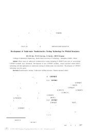
<strong>Si3217x</strong><strong>Si3291x</strong>2. SchematicsSTIPCSRINGCTIPRINGVDDHVVDDDVDDAVDDDVDDHVSLIC-TIPSLIC-RINGVDCDCDRVSDCHSDCLSVBATSTIPCSRINGCDCDRVSDCHSDCLSVBATHWTIPdaaRINGdaa+3V3PCM BUSPCLKFSYNCDTXDRXSPI BUSSCLK/CSSDOSDISDITHRU/RESET/INTVBATProtectionPROT1TIPRING TIP_extRING_extVBATR1061.47M150V654321R1071.47M150VRJ-11654321J1SLICEGNDVBATVDDAC2C60.1uF10uFC70.1uFR103C103±10%200VC40.1uF1KNI0.01uFR105590KNIC104±10%200V0.01uFVDDHV 1VDDD 18VDDA 28150V150VSTIPAC 30SRINGAC 31STIPDC 29VDDREG 19SRINGDC 32PCLKFSYNCDTXDRX871213C101C1020.01uF200V 200V±10% ±10%R17137KVDCDC/DC ConverterDCDCVDCC1000.1uF±10%R108 110KDCDRV+3V3VBATSDCHR249.9K±0.5%R1910KGNDDCDC1C84.7nF±10%R1001.65M150VC1050.1uF200VUse D1 instead of R110if there is a power crossrequirement.VBATRJ-11654321J2DAA654321TIP 40RING 38U1SVDC 21DCDRV 17DCFF14SDCH 15SDCL16SVBAT22SI3217xSCLKCSBSDOSDISDITHRU46325CAPP 24C1AC2A1110CAPM 25GPIO1/STIPCGPIO2/SRINGC343326IREFQGND 27NCNCNCNC35373941CAPLB 23RESETINTB20HWBIASHWBIAS9VBATGNDDSi3217836EPAD242EPAD1D1BAS21HT1NITipRingDAA C1AC2AR1041KC1070.1uFR102 681K0.01uFR109 110KR115R1100C110uFR101 681KFigure 20. Top Level SchematicGND26 Rev. 1.1
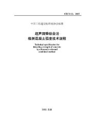
<strong>Si3217x</strong><strong>Si3291x</strong>C1AC2AGNDR21256.2R21356.2Y2Y2ISOLATION BarrierC2041uF50VC20133pFR2091MR2011.07K1/2WNo Ground Plane In DAA AreaR210536 1/4WQ201MMBTA42LT1R2033.65K1/2W150R202R21173.21/2WMMBTA06LT1Q205Q204MMBTA06LT1R2042.49K1/2WR205100KQ202 MMBTA92LT1R206100KQ203MMBTA42LT1C2060.1uFZ20143VIGNDC203R233Optional CID Population250VNIR232NI3.9nFFB202FB2035.1M150V20M150V250VNI150VC231120pFD201NI600 OhmR23620M150VOptional NoiseReduction600 OhmR23120MR207 150VR230R23720M150VFB2015.1M15M 150V150VNINIOptional CID Population600 OhmNI68pFC232Y2C209C208680pF680pFY2 Y2Optional longitudinalbalance enhancementRingTipMMBD3004S-7-FC2050.1uF12345678U202QEDCTRXIBC1BC2BVREGRNG1DCT216IGND 15DCT314QB 13QE212SC 11VREG210RNG29Si32919C2100.01uFC2072.7nF50VR20815M250VC230120pFNID202NIFB204600 OhmP3100SBRV201MMBD3004S-7-FC20233pFFigure 21. DAARev. 1.1 27
<strong>Si3217x</strong><strong>Si3291x</strong>This design is optimizedfor VDC=8V-16VCommercial Temp Only 0C-70CVBAT -95VIBAT
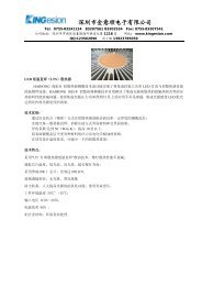
30 Rev. 1.1<strong>Si3217x</strong><strong>Si3291x</strong>TIPRINGTIP_extRING_extEGNDVBATVBATVBAT±10%200VC1080.01uFC1080.01uFtRT150PTCtRT150PTCR15015R15015tRT151PTCtRT151PTCR15115R15115C1500.1uF200VC1500.1uF200VU151TISP61089BDRU151TISP61089BDRK11-VREF2NC 3K24K25A6A7K18Figure 24. Protection
<strong>Si3217x</strong><strong>Si3291x</strong>3. Bill of MaterialsTable 15. <strong>Si3217x</strong>/<strong>Si3291x</strong> Bill of Materials (Excluding DC-DC)Reference Description Mfr Part Number MfrC1CAP, 10uF, 6.3V, ±20%, X5R, 0603 C0603X5R6R3-106M Venkel(Not Installed)D1(Not Installed)R105(Not Installed)DIO, SINGLE, 250V, 200mA, SOT323 BAS21HT1 On SemiRES, 590K, 1/10W, ±1%, ThickFilm, 0805 CR0805-10W-5903F VenkelC2 C4 C7 C100CAP, 0.1uF, 10V, ±10%, X7R, 0402 C0402X7R100-104K VenkelC107C6 CAP, 10uF, 6.3V, ±20%, X5R, 0603 C0603X5R6R3-106M VenkelC8 CAP, 4.7nF, 16V, ±10%, X7R, 0402 C0402X7R160-472K VenkelC101 C102CAP, 0.01uF, 200V, ±10%, X7R, 0805 C0805X7R201-103K VenkelC103 C104C105 CAP, 0.1uF, 200V, ±20%, X7R, 1206 C1206X7R201-104M VenkelJ1 1 Port SMT RJ11 5555077-2 AMPR1 RES, 15 Ohm, 1/10W, ±1%, ThickFilm, 0805 CR0805-10W-15R0F VenkelR2 RES, 49.9K, 1/16W, ±0.5%, ThickFilm, 0603 CR0603-16W-4992D VenkelR17 RES, 137K, 1/16W, ±1%, ThickFilm, 0402 CR0402-16W-1373F VenkelR19 RES, 10K, 1/16W, ±5%, ThickFilm, 0402 CR0402-16W-103J VenkelR101 R102 RES, 681K, 1/10W, ±1%, ThickFilm, 0805 CR0805-10W-6813F VenkelR103 R104 RES, 1K, 1/10W, ±1%, ThickFilm, 0603 CR0603-10W-1001F VenkelR106 R107 RES, 1.47M, 1/8W, ±1%, ThickFilm, 1206 CR1206-8W-1474F VenkelR108 R109 RES, 110K, 1/16W, ±1%, ThickFilm, 0402 CR0402-16W-1103F VenkelR110 RES, 0 Ohm, 2A, ThickFilm, 0805 CR0805-10W-000 VenkelU1 Single SLIC Integrated HV Interface, wideband, DAA Si32178-B-FM SiLabsC108 CAP, 0.01uF, 200V, ±10%, X7R, 0805 C0805X7R201-103K VenkelC150 CAP, 0.1uF, 200V, ±20%, X7R, 1206 C1206X7R201-104M VenkelRT150 RT151 PTC, Telecom PTC Resettable Fuses, SMT MF-SM013/250-2 BournsR150 R151 RES, 15 Ohm, 1/10W, ±1%, ThickFilm, 0805 CR0805-10W-15R0F VenkelU151 SLIC Protector TISP61089BDR BournsC230 C231(Not Installed)CAP, 120pF, 250V, ±10%, X7R, 0805 C0805X7R251-121K VenkelC232(Not Installed)R230 R232(Not Installed)CAP, 68pF, 250VRMS, ±10%, Y2, 1808 GA342D1XGF680JY02L MuRataRES, 15M, 1/8W, ±5%, ThickFilm, 0805 CR0805-8W-156J VenkelRev. 1.1 31
<strong>Si3217x</strong><strong>Si3291x</strong>R231 R233(Not Installed)R236 R237(Not Installed)Table 15. <strong>Si3217x</strong>/<strong>Si3291x</strong> Bill of Materials (Excluding DC-DC)Reference Description Mfr Part Number MfrRES, 5.1M, 1/8W, ±5%, ThickFilm, 0805 CR0805-8W-515J VenkelRES, 20M, 1/8W, ±5%, ThickFilm, 0805 CR0805-8W-206J VenkelC201 C202 CAP, 33pF, 250VRMS, ±5%, Y2, 1808 GA342D1XGF330JY02L MuRataC203 CAP, 3900pF, 250V, ±20%, X7R, 0805 C0805X7R251-392M VenkelC204 CAP, 1uF, 100V, ±10%, X7R, 1210 C1210X7R101-105K VenkelC205 C206 CAP, 0.1uF, 10V, ±10%, X7R, 0402 C0402X7R100-104K VenkelC207 CAP, 2.7nF, 50V, ±20%, X7R, 0603 C0603X7R500-272M VenkelC208 C209 CAP, 680pF, 250VRMS, ±10%, Y2, 1808 SCC1808X681K502T Holy StoneC210 CAP, 0.01uF, 10V, ±20%, X7R, 0402 C0402X7R100-103M VenkelD201 D202 DIO, DUAL Series, 300V, 225mA, SOT23 MMBD3004S-7-F Diodes Inc.FB201 FB202FERRITE BEAD, 600 @100MHZ BLM18AG601SN1 MuRataFB203 FB204J2 1 Port SMT RJ11 5555077-2 AMPQ201 Q203 TRANSISTOR, NPN, High Voltage, SOT23 MMBTA42LT1 On SemiQ202 TRANSISTOR, PNP, High Voltage, SOT23 MMBTA92LT1 On SemiQ204 Q205 TRANSISTOR, NPN, DRIVER, SOT23 MMBTA06LT1 On SemiRV201 SIDACTOR BI 275V 250A DO-214AA P3100SBL LittelfuseR201 RES, 1.07K, 1/2W, ±1%, ThickFilm, 2010 CR2010-2W-1071F VenkelR202 RES, 150 Ohm, 1/16W, ±1%, ThickFilm, 0402 CR0402-16W-1500F VenkelR203 RES, 3.65K, 1/2W, ±1%, ThickFilm, 2010 CR2010-2W-3651F VenkelR204 RES, 2.49K, 1/2W, ±1%, ThickFilm, 2010 CR2010-2W-2491F VenkelR205 R206 RES, 100K, 1/16W, ±5%, ThickFilm, 0402 CR0402-16W-104J VenkelR207 R208 RES, 20M, 1/8W, ±5%, ThickFilm, 0805 CR0805-8W-206J VenkelR209 RES, 1M, 1/16W, ±1%, ThickFilm, 0402 CR0402-16W-1004F VenkelR210 RES, 536 Ohm, 1/4W, ±1%, ThickFilm, 1206 CR1206-4W-5360F VenkelR211 RES, 73.2 Ohm, 1/2W, ±1%, ThickFilm, 2010 CR2010-2W-73R2F VenkelR212 R213 RES, 56.2 Ohm, 1/16W, ±1%, ThickFilm, 0402 CR0402-16W-56R2F VenkelU202 IC, Global DAA Line Side w/Voice features attaches to Si32919-A-FS SiLabsthe <strong>Si3217x</strong> SLICZ201 DIO, ZENER, 43V, 500 mW, SOD123 BZT52C43-7-F Diodes Inc.32 Rev. 1.1
<strong>Si3217x</strong><strong>Si3291x</strong>Table 16. <strong>Si3217x</strong> Flyback DC-DC Bill of MaterialsReference Description Mfr Part Number MfrC124 C125CAP, 0.1uF, 200V, ±20%, X7R, 1206 C1206X7R201-104M Venkel(Not Installed)C128(Not Installed)C133(Not Installed)C134(Not InstalledD125(Not Installed)D126(Not Installed)R130(Not Installed)CAP, 470pF, 50V, ±20%, X7R, 0402 C0402X7R500-471M VenkelCAP, 68pF, 200V, ±5%, COG, 0805 C0805C0G201-680J VenkelCAP, 470pF, 100V, ±10%, X7R, 0603 C0603X7R101-471K VenkelDIO, SWITCH, 200mA, 75V, SOD523 BAS16XV2T1G On SemiDIO, ZENER, 75V, 200 mW, SOD323 BZX384C75-V VishayRES, 150 Ohm, 1/4W, ±1%, ThickFilm, 1206 CR1206-4W-1500F VenkelR139 RES, 15 Ohm, 1/4W, ±5%, ThickFilm, 1206 CR1206-4W-150J Venkel(Not Installed)C121 C126 CAP, 0.1uF, 25V, ±20%, X7R, 0603 C0603X7R250-104M VenkelC122 C123 CAP, 0.1uF, 200V, ±20%, X7R, 1206 C1206X7R201-104M VenkelC127 CAP, 470pF, 50V, ±20%, X7R, 0402 C0402X7R500-471M VenkelC130CAP, 68uF, 63V, ±20%, AL, 8X11.5MM,EEUFC1J680 PanasonicLow ImpedanceD120 DIO, FAST, 300V, 1A, SMA ES1F FairchildQ120TRANSISTOR, MOSFET, N-CHNL,ZXMN10A11GZetex2.0W Switching, SOT223Q121 TRANSISTOR, PNP, SOT23 MMBT3906-7-F Diodes Inc.Q122TRANSISTOR, MOSFET, N-CHNL,BSS138Zetex360mW Small signal, SOT23Q123 TRANSISTOR, NPN, GP, SOT23 MMBT3904 FairchildR100 RES, 1.65M, 1/10W, ±1%, ThickFilm, 0805 CR0805-10W-1654F VenkelR121 RES, 0.1 Ohm, 1/2W, ±1%, ThickFilm, 1210 LCR1210-R100F VenkelR122 RES, 15 Ohm, 1/4W, ±5%, ThickFilm, 1206 CR1206-4W-150J VenkelR123 RES, 220 Ohm, 1/16W, ±5%, ThickFilm, 0402 CR0402-16W-221J VenkelR124 R140 RES, 0 Ohm, 1A, ThickFilm, 0402 CR0402-16W-000 VenkelR125 RES, 681K, 1/10W, ±1%, ThickFilm, 0805 CR0805-10W-6813F VenkelR126 RES, 68K, 1/16W, ±5%, ThickFilm, 0402 CR0402-16W-683J VenkelRev. 1.1 33
<strong>Si3217x</strong><strong>Si3291x</strong>Table 16. <strong>Si3217x</strong> Flyback DC-DC Bill of MaterialsReference Description Mfr Part Number MfrR141 R142 RES, 0 Ohm, 1A, ThickFilm, 0402 CR0402-16W-000 VenkelT120 TRANSFORMER, Flyback, 8.0uH Primary, 100nHLeakage, 1:3, 1 Tap, SMTUTB01890sUTB01701sXF0086-EP7SUMECUMECXFMRS Inc34 Rev. 1.1
<strong>Si3217x</strong><strong>Si3291x</strong>Table 17. <strong>Si3217x</strong> Buck Boost DC-DC Bill of MaterialsReference Description Mfr Part Number ManufacturerC122 CAP, 0.1uF, 100V, ±20%, X7R, 0603 C0603X7R101-104M VenkelC120 C123 CAP, 10uF, 100V, ±20%, AL, 5X11MM ECA2AM100 PanasonicC121 C125 CAP, 0.1uF, 25V, ±20%, X7R, 0603 C0603X7R250-104M VenkelC126 CAP, 0.01uF, 10V, ±20%, X7R, 0402 C0402X7R100-103M VenkelD120 DIO, FAST, 200V, 1A SMA ES1D Diodes Inc.D121 DIO, SWITCH, 75V, 300mA, SOT23 BAS16-7-F Diodes Inc.L120 Power Inductor, Shielded DR127-101-R Cooper BussmanQ120 TRANSISTOR, PNP, 140V,MEDIUM POWER LOW SAT, SOT223ZXTP2014GZetexQ121 TRANSISTOR, NPN, SOT23 MMBT2222LT1 On SemiR100 RES, 1.65M, 1/10W, ±1%, ThickFilm, 0805 CR0805-10W-1654F VenkelR120 R126R127 R128RES, 1.0 Ohm, 1/16W, ±1%, ThickFilm, 0402 CR0402-16W-1R00F VenkelR122 RES, 15 Ohm, 1/10W, ±1%, ThickFilm, 0805 CR0805-10W-15R0F VenkelR124 RES, 120 Ohm, 1/10W, ±1%, ThickFilm, 0603 CR0603-10W-1200F VenkelR125 RES, 200 Ohm, 1/10W, ±1%, ThickFilm, 0603 CR0603-10W-2000F VenkelR129 R130 RES, 47K, 1/16W, ±1%, ThickFilm, 0402 CR0402-16W-4702F VenkelRev. 1.1 35
<strong>Si3217x</strong><strong>Si3291x</strong>4. OverviewThe <strong>Si3217x</strong> series provides all SLIC, codec, DTMFdetection, and signal generation functions needed forone complete analog telephone interface. The <strong>Si3217x</strong>performs all battery, over-voltage, ringing, supervision,codec, hybrid, and test (BORSCHT) functions; it alsosupports extensive metallic loop testing capabilities.The <strong>Si3217x</strong> provides a standard voice-band (200 Hz–3.4 kHz) audio codec and, optionally, an audio codecwith both wideband (50 Hz–7 kHz) and standard voicebandmodes. The wideband mode provides anexpanded audio band with a 16 kHz sample rate forenhanced audio quality while the standard voice-bandmode provides standard telephony audio bandwidth.The <strong>Si3217x</strong> incorporates a programmable dc-dcconverter controller that reacts to line conditions toprovide the optimal battery voltage required for eachline-state. <strong>Si3217x</strong> ICs are available with voltage ratingsof –110 V or –135 V to support a wide range of ringingvoltages; see "10. Ordering Guide‚" on page 49 for thevoltage rating of each <strong>Si3217x</strong> version.Programmable on-hook voltage, programmable offhookloop current, reverse battery operation, loop orground start operation, and on-hook transmission aresupported. Loop current and voltage are continuouslymonitored by an integrated monitoring ADC.The <strong>Si3217x</strong> supports balanced 5 REN ringing with orwithout a programmable dc offset. The available voltageoffset, frequency, waveshape, and cadence options aredesigned to ring the widest variety of terminal devicesand to reduce external controller requirements.A complete audio transmit and receive path isintegrated, including ac impedance and hybrid gain.These features are software-programmable, allowing asingle hardware design to meet global requirements.Select part numbers in the series also implement SiliconLaboratories’ capacitive isolation technology to enable aseamless connection to <strong>Si3291x</strong> DAA ICs. Digital voicedata transfer occurs over a standard PCM bus. Controldata is transferred using a standard SPI. <strong>Si3217x</strong> ICsare available in a 42-pin QFN package. The <strong>Si3291x</strong>devices are available in a 16-pin SOIC.5. FXS Features5.1. DC Feed CharacteristicsProSLIC internal linefeed circuitry provides completelyprogrammable dc feed characteristics.When in the active state, the ProSLIC operates in one ofthree dc linefeed operating regions: a constant-voltageregion, a constant-current region, or a resistive region,as shown in Figure 25. The constant-voltage region hasa low resistance, typically 160 . The constant-currentregion approximates infinite resistance.V_ILIMV_RFEEDV_VLIMVTR(V)I_VLIMI_RFEEDConstant V RegionResistive RegionI_ILIMFigure 25. Dual ProSLIC DC FeedCharacteristics5.2. Linefeed Operating StatesILOOP (mA)The linefeed interface includes eight different registerprogrammableoperating states as listed in Table 18.The Open state is the default condition in the absenceof any preloaded register settings. The device may alsoautomatically enter the open state in the event of alinefeed fault condition.5.3. Line Voltage and Current MonitoringThe ProSLIC continuously monitors the TIP, RING, andbattery voltages and currents via an on-chip ADC andstores the resulting values in individual RAM locations.Additionally, the loop voltage (V TIP –V RING ), loop current,and longitudinal current values are calculated based onthe TIP and RING measurements and are stored inunique register locations for further processing. TheADC updates all registers at a rate of 2 kHz or greater.Constant I Region36 Rev. 1.1
<strong>Si3217x</strong><strong>Si3291x</strong>5.4. Power Monitoring and Power FaultDetectionThe <strong>Si3217x</strong> line monitoring functions are used tocontinuously protect against excessive powerconditions. The <strong>Si3217x</strong> contains an on-chip, analogsensing diode that provides real-time temperature dataand turns off the device when a preset threshold isexceeded.If the <strong>Si3217x</strong> detects a fault condition or overpowercondition, it automatically sets that device to the openstate and generates a "power alarm" interrupt.The interrupt can be masked, but masking theautomatic transition to open is not recommended sinceit is used to protect the Si3217 HVIC under excessivepower conditions.The various power alarms and linefeed faults supportingautomatic intervention are described below.1. Total power exceeded.2. Excessive foreign current or voltage on TIP and/orRING.3. Thermal shutdown event.5.5. Thermal Overload ShutdownIf the die temperature exceeds the maximum junctiontemperature threshold, TJmax, of 145 °C or 200 °C, thedevice has the ability to shut itself down to a low-powerstate without user intervention. The thermal shutdowncircuit contains a sufficient amount of hysteresis and/orturn-on delay time so as to remain shut down during apower cross event, where 50 Hz or 60 Hz, 600 V, isconnected to TIP and/or RING.Table 18. Linefeed Operating StatesLinefeed StateOpenForward ActiveReverse ActiveForward OHTReverse OHTTIP OpenRING OpenRingingLine DiagnosticsDescriptionOutput is high-impedance, and all line supervision functions are powered down. Audio ispowered down. This is the default state after powerup or following a hardware reset. Thisstate can also be used in the presence of line fault conditions and to generate open switchintervals (OSIs). This state is used in line diagnostics mode as a high impedance state duringlinefeed testing. A power fault condition may also force the device into the open state.Linefeed circuitry and audio are active. In Forward Active state, the TIP lead is more positivethan the RING lead; in Reverse Active state, the RING lead is more positive than theTIP lead. Loop closure and ground key detect circuitry are active.Provides data transmission during an on-hook loop condition (e.g., transmitting caller IDdata between ringing bursts). Linefeed circuitry and audio are active. In Forward OHTstate, the TIP lead is more positive than the RING lead; in Reverse OHT state, the RINGlead is more positive than the TIP lead.Provides an active linefeed on the RING lead and sets the TIP lead to high impedance(>400 k) for ground start operation in forward polarity. Loop closure and ground keydetect circuitry are active.Provides an active linefeed on the TIP lead and sets the RING lead to high impedance(>400 k) for ground start operation in reverse polarity. Loop closure and ground keydetect circuitry are active.Drives programmable ringing signal onto TIP and RING leads with or without dc offset.The channel is put into diagnostic mode. In this mode, the channel has special diagnosticresources available.37 Rev. 1.1
<strong>Si3217x</strong><strong>Si3291x</strong>5.6. Loop Closure DetectionThe <strong>Si3217x</strong> provides a completely programmable loopclosure detection mechanism. The loop closuredetection scheme provides two unique thresholds toallow hysteresis, and also includes a programmabledebounce filter to eliminate false detection. A loopclosure detect status bit provides continuous status, anda maskable interrupt bit is also provided.5.7. Ground Key DetectionThe <strong>Si3217x</strong> provides a ground key detect mechanismusing a programmable architecture similar to the loopclosure scheme. The ground key detect schemeprovides two unique thresholds to allow hysteresis andalso includes a programmable debounce filter toeliminate false detection. A ground key detect status bitprovides continuous status, and a maskable interrupt bitis also provided.5.8. Ringing GenerationThe <strong>Si3217x</strong> provides the ability to generate aprogrammable sinusoidal or trapezoidal ringingwaveform, with or without dc offset. The ringingfrequency, wave shape, cadence, and offset are allregister-programmable. Three ringing modes aresupported: balanced, unbalanced, and low-powerringing (LPR). Figure 26 illustrates the fundamentaldifferences between the three ringing modes.5.9. Polarity ReversalThe <strong>Si3217x</strong> supports polarity reversal for messagewaiting and various other signaling modes. The ramprate can be programmed for a smooth or abrupttransition to accommodate different applicationrequirements.5.10. Two-Wire Impedance SynthesisThe ac two-wire impedance synthesis is generated onchipusing a DSP-based scheme to optimally match theoutput impedance of the <strong>Si3217x</strong> to the referenceimpedance. Most real or complex two-wire impedancescan be generated with appropriate register coefficients.5.11. Transhybrid Balance FilterThe trans-hybrid balance function is implemented onchipusing a DSP-based scheme to effectively cancelthe reflected receive path signal from the transmit path.5.12. Tone GeneratorsThe <strong>Si3217x</strong> includes two digital tone generators thatallow a wide variety of single- or dual-tone frequencyand amplitude combinations. Each tone generator hasits own set of registers that hold the desired frequency,amplitude, and cadence to allow generation of DTMFand call progress tones for different requirements. Thetones can be directed to either receive or transmit paths.TIPRINGVBATBalancedGND GNDTIPGNDTIPRINGVBATRINGVBATUnbalancedLPRFigure 26. Ringing Modes38 Rev. 1.1
<strong>Si3217x</strong><strong>Si3291x</strong>5.13. DTMF DetectionIn DTMF, two tones generate a DTMF digit. One tone ischosen from four possible row tones, and one tone ischosen from four possible column tones. The sum ofthese tones constitutes one of 16 possible DTMF digits.Select <strong>Si3217x</strong> ICs support DTMF detection as outlinedin "10. Ordering Guide‚" on page 49. The DTMFdetector can be utilized by the FXS or FXO interface.5.14. Pulse Metering (Si32171 Only)The pulse metering system for the Si32171 is designedto inject a 12 or 16 kHz billing tone into the audio pathwith maximum amplitude of 2.5 V RMS at TIP and RINGinto a 200 ac load impedance. The tone is generatedin the DSP via a table lookup that guarantees spectralpurity by not allowing drift. The tone will ramp up until itreaches a host-programmed threshold, at which point itwill maintain that level until instructed to ramp down,thus creating a trapezoidal envelope.The amplitude is controlled by an automatic gain controlcircuit (AGC). While the tone is ramping up, the AGCtakes the feedback audio and applies it to a band passfilter, which is programmed for the 12 or 16 kHzfrequency of interest. When the peak is detected, theramp is stopped.See AN340 section 2.3.9 for additional details andconsiderations on Pulse Metering.5.15. DC-DC ControllerThe <strong>Si3217x</strong> integrates a dc-dc controller that operatesfrom a single positive dc input. The controllerdynamically manages an external dc-dc convertercircuit to generate the optimal battery voltage for eachoperating state.5.16. Wideband AudioSelect <strong>Si3217x</strong> ICs support a software-selectablewideband (50 Hz–7 kHz) and narrowband (200 Hz–3.4 kHz) audio codec. The wideband mode provides anexpanded audio band at a 16-bit, 16 kHz sample ratefor enhanced audio quality while maintaining standardtelephony audio compatibility. Wideband audio samplesare transmitted and received on the PCM interfaceusing two consecutive 8 kHz frames.5.17. In-Circuit and Metallic Loop Testing(MLT)A rich set of features is provided for in-circuit testing ofthe FXS system and the connected telephone line(MLT):• Tone generators• Audio diagnostic filters• Digital and analog loop-back modes• Internal test load• Monitor ADC• DSP algorithmsUsing these facilities, it is possible to test the <strong>Si3217x</strong>’sdc-dc converter, codec, line-feed, PCM bus interface,DSP, SPI bus interface, and call progress state-machineas well as testing the connected telephone line andexternal protection circuitry.The audio diagnostic filters on the FXS are intended toprovide programmable filtering of the TX digital audiosignal and calculate the peak and/or average signalpower of the filters’ outputs. The signal powers are thencompared to programmable thresholds. Theprogrammable filters can be used to band-pass filter acertain tone or notch out certain tones, so that the signalpower measurements are frequency selective. Thisfiltering is useful in a telephony system because it canmeasure harmonic distortion, intermodulation, noise,etc.The <strong>Si3217x</strong> incorporates an internal test load with a5k nominal value that can be connected across Tip/Ring (Figure 27). The audio diagnostics system andbuilt-in test load can be used to test the FXS interface(<strong>Si3217x</strong>) itself without requiring an external load, aconnected line, or any relays. This facility can be usedfor production and in-service testing of such things as:• Dial tone draw/break• Audio quality measurements• Pulse digit detection• DC feed• Ringtrip• Polarity reversal• Transmission lossRev. 1.1 39
<strong>Si3217x</strong><strong>Si3291x</strong>MLT, e.g., GR-909, is facilitated by the built-in DSP,monitor ADC, and test load. They provide the ability todetect multiple fault conditions within the CPE as well ason the Tip/Ring pair (T-R). Thirteen different measuredand/or calculated parameters are reported by theMonitor ADC. Host software for use in conjunction withthe ProSLIC API is available from Silicon Labs. TypicalMLT tests include:• Hazardous Potential Test – This checks for acvoltage > 50 V RMS or dc voltage > 135 V betweenTip and Ground (T-G) or Ring and Ground (R-G).• Foreign Electromotive Force Test – Checks T-G orR-G for ac voltage > 10 V RMS or dc voltage > 6 V.Uses same threshold as for hazardous voltage test.• Resistive Faults Test – Checks for dc resistancefrom T-R, T-G or R-G. Any measurement < 150 k isconsidered a resistive fault.• Receiver-Off-Hook Test – Distinguishes between aT-R resistive fault and an off-hook condition.• Ringers Test – Measures the magnitude of theconnected ring load (REN) across T-R. Results are> 0.175 REN and < 5 REN for a valid load• AC Line Impedance (line length) – T-R, T-G, and R-G. Generates a tone at several specific frequencies(audio band) and measures the reflected signalamplitude (complex spectrum) that comes back (withtranshybrid balance filter disabled). The reflectedsignal is then used to calculate the line impedancebased on certain assumptions of wire gauge, etc.• Line Capacitance – T-R, T-G, R-G. Generates alinear ramp function with polarity reversal, andmeasures the time constant.Diagnostic information is available even in the presenceof fault conditions that cause the system’s protectiondevices (fuses, PTCs, etc.) to open. A high-impedancesensing path (pins SRINGC and STIPC) can be used tomeasure the conditions on Tip/Ring even when the FXSsystem is effectively disconnected from the line. Norelay is required and this sensing path inherently meetsDielectric Withstand per GR-49 (> 1000 V).TIPRINGTest LoadR TL = 5.3 k (typical)HVIC_STATE_SPARE[23]0 = Test Load OFF1 = Test Load ONFigure 27. <strong>Si3217x</strong> Internal Test Load Circuit40 Rev. 1.1
<strong>Si3217x</strong><strong>Si3291x</strong>6. FXO Features6.1. Isolation BarrierThe Si32178and <strong>Si3291x</strong> achieve an isolation barrierthrough low-cost, high-voltage capacitors in conjunctionwith Silicon Laboratories’ patented signal processingtechniques.The isolation barrier provides greater than 5 kVisolation.6.2. Power ManagementThe Si32178 FXO circuitry supports four powermanagement modes: reset mode, normal mode, sleepmode and powerdown mode. When in reset mode, theSi32178 FXO is operational, except for thecommunication link to the line-side device (<strong>Si3291x</strong>). Innormal mode, the chipset is fully operational. Sleepmode provides a low-power state that only supports ringdetection, ring validation and wake-up-on-ring features.The powerdown mode puts the chipset in a nonfunctionalstate that requires the least power. Normaloperation can be restored by issuing a reset.6.3. In-Circuit TestingSix FXO loopback modes are available to supportproduction line testing and end-user diagnostics. Fourof the test modes require a line-side power source.6.4. Transmit/Receive Full-Scale LevelThe Si32178 supports programmable maximumtransmit and receive levels. The default signal levelsupported by the Si32178 is 0 dBm into a 600 load.Two additional modes of operation offer increasedtransmit and receive level capability to enable use of theDAA in applications that require higher signal levels.The full-scale mode increases the full-scale signal levelto +3.2 dBm into a 600 load or 1 dBV into allreference impedances. The enhanced full-scale modeincreases the full-scale signal level to +6.0 dBm into a600 load or 1.5 dBV into all reference impedances.The full-scale and enhanced full-scale modes providethe ability to trade off TX power and TX distortion for apeak signal. By using the programmable digital gainregisters in conjunction with the enhanced full-scalesignal level mode, a specific power level (+3.2 dBm forexample) can be achieved across all ac terminationsettings.6.5. Line Voltage MeasurementLine voltage can be measured in both on-hook and offhookstates with a resolution of 1V per bit and a range of-128 to 127V. Values between –3 to 3 V can, optionally,be forced to zero to mask measurements between –2 to2 V, which may be unpredictable.Polarity reversal detection is triggered whenever thesign of the measured value changes between positiveand negative states.6.6. Loop Current MeasurementLoop current sensing is available in the off-hook state.Loop currents are measurable down to the minimumoperating loop current of the DAA, which isprogrammable to 10, 12, 14 or 16mA. Currents can bemeasured with a resolution of 1.1 or 3.3 mA over arange of 0 to 127 mA. If the loop current exceeds theprogrammed current limit of the device (160 mA or60 mA), an over-current event is reported.6.7. Parallel Handset DetectionThe integrated line sensing capabilities of the Si32178can be used to detect a parallel handset going off-hook.When off-hook, a significant change in loop currentsignals a parallel phone off-hook or on-hook event.When on-hook, a significant drop in line-voltage signalsa parallel phone off-hook event.6.8. DC TerminationThe DAA has programmable settings for the dcimpedance, current limiting, minimum operational loopcurrent and TIP/RING voltage. The dc impedance of theDAA is normally represented with a 50 slope asshown in Figure 28, but can be changed to an 800 slope. This higher dc termination presents a higherresistance to the line as loop current increases.Voltage Across DAA (V)121110987FCC DCT Mode6.01 .02 .03 .04 .05 .06 .07 .08 .09 .1 .11Loop Current (A)Figure 28. FCC Mode I/V CharacteristicsRev. 1.1 41
<strong>Si3217x</strong><strong>Si3291x</strong>For applications requiring current limiting per the TBR21standard, the ILIM bit may be set to select this mode. Inthis mode, the dc I/V curve is changed to a 2000 slope above 40 mA, as shown in Figure 29. This allowsthe DAA to operate with a 50 V, 230 feed, which is themaximum linefeed specified in the TBR21 standard.TBR21 DCT Mode45403530252015105.015 .02 .025 .03 .035 .04 .045 .05 .055 .06Loop Current (A)Figure 29. TBR21 Mode I/V CharacteristicsVoltage Across DAA (V)6.9. AC TerminationThe Si32911 is optimized to support only CTR21/TBR21and FCC-compliant countries. The Si32919 is aglobally-compliant DAA solution. The following tablehighlights the available ac termination settings in eachdevice:Table 19. AC Termination Settings for the<strong>Si3291x</strong> Line-Side DevicesSi32911 Si32919 AC Termination 600 900 270 + (750 || 150 nF)275 + (780 || 150 nF) 220 + (820 || 120 nF)220 + (820 || 115 nF) 370 + (620 || 310 nF) 320 + (1050 || 230 nF) 370 + (820 || 110 nF) 270 + (750 || 150 nF) 275 + (780 || 115 nF) 120 + (820 || 110 nF) 350 + (1000 || 210 nF) 200 + (680 || 100 nF) 600 + 2.16 µF 900 + 1 µF 900 + 2.16 µF 600 + 1 µF Global complex impedance6.10. Ring DetectionThe Si32178 supports either full- or half-wave ringdetection. With full-wave ring detection, the designercan detect a polarity reversal of the ring signal. See“Transhybrid Balance” on page 43. The Si32919supports three programmable ring thresholds: 15 V±10%, 21 V ±10%, and 45 V ±10%. The Si32911supports 15 V ±10%.6.11. Ring ValidationRing validation prevents false triggering of a ringdetection by validating the ring parameters. Invalidsignals, such as a line-voltage change when a parallelhandset goes off-hook, pulse dialing, or a high-voltageline test are ignored. Ring validation can be enabledduring normal operation and in sleep mode when a validexternal PCLK signal is supplied.The ring validation circuit calculates the time betweenalternating crossings of positive and negative ringthresholds for a programmed period of time to validatethat the ring frequency is within tolerance. High and lowfrequency tolerances are also programmable.42 Rev. 1.1
<strong>Si3217x</strong><strong>Si3291x</strong>6.12. Ringer Impedance and ThresholdThe ring detector on the <strong>Si3291x</strong> device is resistivelycoupled to the line. This coupling produces a high ringerimpedance to the line of approximately 20 Mto meetthe majority of country PTT specifications including FCCand TBR21.A synthesized ringer impedance can also be enabled tocomply with maximum ringer impedance specificationsof several countries including Poland, South Africa, andSlovenia.6.13. Pulse Dialing and Spark QuenchingPulse dialing is accomplished by going off- and on-hookto generate make and break pulses. The nominal rate is10 pulses per second. Some countries have strictspecifications for pulse fidelity including make andbreak times, make resistance, and rise and fall times. Ina traditional, solid-state dc holding circuit, there are anumber of issues in meeting these requirements. The<strong>Si3217x</strong> dc holding circuit has active control of the onandoff-hook transients to maintain pulse dialing fidelity.Spark quenching requirements in countries, such asItaly, the Netherlands, South Africa, and Australia, dealwith the on-hook transition during pulse dialing. TheSi32919 supports three distinct on-hook speeds to passspark quenching tests without additional BOMcomponents.6.14. Receive Overload DetectionThe Voice DAA chipset is capable of monitoring andreporting receive overload conditions on the line. Billingtones, parallel phone off-hook events, polarity reversalsand other disturbances on the line may trigger multiplelevels of overload detection.Certain events, such as billing tones, can be sufficientlylarge to disrupt the line-derived power supply of an<strong>Si3291x</strong> line side device. The <strong>Si3291x</strong> devices supporta dynamically-enabled high-impedance mode to ensurethat they maintain the off-hook line state during theseevents.6.15. On-Hook Line MonitorThe on-hook line monitor mode allows the Si32178 toreceive line activity when in an on-hook state. Thismode is typically used to detect caller ID data (see“6.16. Transhybrid Balance” ). Caller ID data can begained up or attenuated in the device.6.16. Transhybrid BalanceThe Si32178 contains an on-chip analog hybrid thatperforms the 2- to 4-wire conversion and near-end echocancellation. This hybrid circuit is adjusted for each actermination setting selected to achieve a minimumtranshybrid balance of 20 dB when the line impedancematches the selected ac termination.The <strong>Si3217x</strong> also offers a programmable digital hybridstage for additional near-end echo cancellation. Foreach ac termination setting, the hybrid can beprogrammed with coefficients to increase cancellation ofreal-world line impedances. This digital filter canproduce 10 dB or greater of near-end echo cancellationin addition to the trans-hybrid loss from the analoghybrid circuitry.7. System Interfaces7.1. SPI Control InterfaceThe controller interface to the <strong>Si3217x</strong> is a 4-wireinterface modeled after microcontroller and serialperipheral devices. The interface consists of a clock(SCLK), chip select (CS), serial data input (SDI), andserial data output (SDO). In addition, the ProSLICdevices feature a serial data through output (SDITHRU)to support operation of up to 16 channels using a singlechip select line. The FXS port and FXO port (if availableand enabled) each occupy one SPI channel. The deviceoperates with both 8-bit and 16-bit SPI controllers.7.2. PCM Interface and CompandingThe <strong>Si3217x</strong> contains a flexible, programmableinterface for the transmission and reception of digitalPCM samples. PCM data transfer is controlled by thePCM clock (PCLK) and frame sync (FSYNC) inputs aswell as the PCM Mode Select, PCM Transmit Start, andPCM Receive Start settings.The interface can be configured to support from 8 to128 8-bit time slots in each 125 µs frame,corresponding to a PCM clock (PCLK) frequency rangeof 256 kHz to 8.192 MHz. 1.544 MHz is also supported.The <strong>Si3217x</strong> supports both µ-255 Law (µ-Law) and A-law companding formats in addition to 16-bit linear datamode with no companding.Rev. 1.1 43
<strong>Si3217x</strong><strong>Si3291x</strong>8. Pin Descriptions: <strong>Si3217x</strong>VDDHVSDISDOSCLKSDITHRUCSFSYNCPCLKINTC2A/NCC1A/NCDTXDRXDCFF1 42 41 40 39 38 37 36 352345678910111213EPAD2EPAD134333231302928272625242314 15 16 17 18 19 20 21 22NCGPIO1/STIPCGPIO2/SRINGCSRINGDCSRINGACSTIPACSTIPDCVDDAQGNDIREFCAPMCAPPCAPLBSVBATSDCHSDCLDCDRVVDDDVDDREGRSTSVDCEPAD2NCTIPNCRINGNCVBATPin # Pin Name Description1 VDDHV IC Voltage Supply.2 SDI3 SDO4 SCLK5 SDITHRU6 CS7 FSYNC8 PCLK9 INT10 C2A/NCSerial Port Data Input.Serial port control data input.Serial Port Data Output.Serial port control data output.Serial Port Bit Clock Input.Serial port clock input. Controls the serial data on SDO and latches the data onSDI.SDI Passthrough.Cascaded SDI output signal for daisy-chain mode.Chip Select Input.Active low. When inactive, SCLK and SDI are ignored and SDO is high impedance.When active, the serial port is operational.Frame Sync Clock Input.8 kHz frame synchronization signal for the PCM bus. May be short or long pulseformat.PCM Bus Clock Input.Clock input for PCM bus timing.Interrupt Output.Maskable interrupt output. Open drain output for wire-ORed operation.Si32178 only: Connects to one side of the isolation capacitor C1. Used to communicatewith the FXO line-side device. For versions of <strong>Si3217x</strong> that do not support anFXO I/F or if the FXO line-side device is not populated this pin should be left unbiased.44 Rev. 1.1
<strong>Si3217x</strong><strong>Si3291x</strong>Pin # Pin Name Description11 C1A/NCSi32178 only: Connects to one side of the isolation capacitor C2. Used to communicatewith theFXO line-side device. For versions of <strong>Si3217x</strong> that do not support anFXO I/F or if the FXO line-side device is not populated this pin should be left unbiased.12 DTX13 DRX14 DCFF15 SDCHTransmit PCM Data Output.Output data to PCM bus.Transmit PCM Data Input.Input data from PCM bus.DC Feed-Forward/High Current General Purpose Output.Feed-forward drive of external bipolar transistors to improve dc-dc converter efficiencyDC Monitor.DC-DC converter monitor input used to detect overcurrent situations in the converter16 SDCLDC Monitor.DC-DC converter monitor input used to detect overcurrent situations in the converter.17 DCDRVDC Drive/Battery Switch.DC-DC converter control signal output which drives external bipolar transistor.18 VDDDIC Voltage Supply.Digital power supply for internal digital circuitry.19 VDDREG Regulated Core Power Supply.20 RSTReset Input.Active low input. Hardware reset used to place all control registers in the defaultstate.21 SVDCDC-DC Input Voltage Sensor.Serves V DC input to dc-dc converter.22 SVBATVBAT Sense.Analog current input used to sense voltage on dc-dc converter output voltage lead.23 CAPLB Calibration Capacitor.24 CAPPSLIC Stabilization Capacitor.Capacitor used in low pass filter to stabilize SLIC feedback loops.25 CAPMSLIC Stabilization Capacitor.Capacitor used in low pass filter to stabilize SLIC feedback loops.26 IREFCurrent Reference Input.Connects to an external resistor used to provide a high accuracy reference current.27 QGND Quiet Ground Reference Input.28 VDDAAnalog Supply Voltage.Analog power supply for internal analog circuitry.Rev. 1.1 45
<strong>Si3217x</strong><strong>Si3291x</strong>Pin # Pin Name Description29 STIPDC30 STIPAC31 SRINGAC32 SRINGDC3334GPIO2SRINGCGPIO1STIPC35 NC36 VBAT37 NC38 RING39 NC40 TIP41 NC42 NC— EPAD1— EPAD2TIP DC Sense.Analog current input used to sense voltage on the TIP lead.TIP AC Sense Input.Analog ac input used to detect voltage on the TIP lead.RING AC Sense Input.Analog ac input used to detect voltage on the RING leadRING DC Sense Input.Analog current input used to sense voltage on the RING lead.General Purpose I/O.RING Coarse Sense Input.Voltage sensing outside protection circuit.General Purpose I/O.TIP Coarse Sense Input.Voltage sensing outside protection circuit.No Connect.This pin should be left unbiased.Battery Voltage Supply.Connect to battery supply from dc-dc converter.No Connect.This pin should be left unbiased.RING Terminal.Connect to the RING lead of the subscriber loop.No Connect.This pin should be left unbiased.TIP Terminal.Connect to the TIP lead of the subscriber loop.No Connect.This pin should be left unbiased.No Connect.This pin is internally connected to EPAD2 and should be left unbiased.Exposed paddle.Connect to ground.Exposed paddle.Connect to electrically-isolated low thermal impedance inner layer and/or backsidethermal plane using multiple thermal vias.46 Rev. 1.1
<strong>Si3217x</strong><strong>Si3291x</strong>9. Pin Descriptions: <strong>Si3291x</strong>QE116DCT2DCT215IGNDRX314DCT3IBC1B451312QBQE2C2BVREG671110SCVREG2RNG189RNG2Pin # Pin Name Description1 QE2 DCT3 RX4 IB5 C1B6 C2B7 VREG8 RNG19 RNG210 VREG211 SC12 QE2Transistor Emitter.Connects to the emitter of Q3.DC Termination.Provides dc termination to the telephone network.Receive Input.Serves as the receive side input from the telephone network.Internal Bias.Provides a bias voltage to the device.Isolation Capacitor 1B.Connects to one side of isolation capacitor C1. Used to communicate with thesystem-side device (Si32178).Isolation Capacitor 2B.Connects to one side of isolation capacitor C2. Used to communicate with thesystem-side device (Si32178).Voltage Regulator.Connects to an external capacitor to provide bypassing for an internal power supply.Ring 1.Connects through a resistor to the TIP lead of the telephone line. Provides the ring and callerID signals to the DAA.Ring 2.Connects through a resistor to the RING lead of the telephone line. Provides the ring andcaller ID signals to the DAA.Voltage Regulator 2.Connects to an external capacitor to provide bypassing for an internal power supply.SC Connection.Enables external transistor network. Should be tied through a 0 resistor to I GND .Transistor Emitter 2.Connects to the emitter of Q4.Rev. 1.1 47
<strong>Si3217x</strong><strong>Si3291x</strong>Pin # Pin Name Description13 QB14 DCT315 IGND16 DCT2Transistor Base.Connects to the base of transistor Q4.DC Termination 3.Provides dc termination to the telephone network.Isolated Ground.Connects to ground on the line-side interface.DC Termination 2.Provides dc termination to the telephone network.48 Rev. 1.1
<strong>Si3217x</strong><strong>Si3291x</strong>10. Ordering GuideFXS P/N Description Max Vbat TemperatureSi32176-B-FM FXS, wideband capable –110 V 0 to 70 °CSi32176-B-GM FXS, wideband capable –110 V –40 to 85 °CSi32177-B-FM FXS, wideband capable –135 V 0 to 70 °CSi32177-B-GM FXS, wideband capable –135 V –40 to 85 °CSi32178-B-FMFXS, DTMF detection, wideband capable withFXO support–110 V 0 to 70 °CSi32171-B-FM FXS, DTMF detection, pulse metering –110 V 0 to 70 °CSi32171-B-GM FXS, DTMF detection, pulse metering –110 V –-40 to 85 °CNote: Adding the suffix "R" to the part number (eg Si32178-B-FMR) denotes tape and reel.FXO P/N Region RingerThresholdsOn-hookSpeedsRoHSCompliantTemperatureSi32911-A-FS FCC/CTR21 1 2 Yes 0 to 70 °CSi32919-A-FS Global 3 3 Yes 0 to 70 CNote: Adding the suffix “R” to the part number (eg. Si32919-A-FSR) denotes tape and reel.Rev. 1.1 49
<strong>Si3217x</strong><strong>Si3291x</strong>11. Product IdentificationThe product identification number is a finished goods part number or is specified by a finished goods part number,such as a special customer part number.Example:Si32178-B-FMRProduct DesignatorProduct RevisionShipping OptionBlank = TubesR = Tape and ReelPackage TypeM = QFN/NBAS = SOICPart Type / Lead FinishF = Commercial / RoHS-CompliantG = Industrial / RoHS-Compliant50 Rev. 1.1
<strong>Si3217x</strong><strong>Si3291x</strong>12. Package Markings (Top Marks)12.1. Si32178 Top Mark12.2. <strong>Si3217x</strong> Top Mark ExplanationLine 1 Marking: Device Part Number e.g., Si32178-FMLine 2 Marking:Line 3 Marking:YY = YearWW = Work WeekTTTTTT = Mfg CodeCircle = 0.5 mm DiameterLower Left-JustifiedCircle = 1.3 mm DiameterCenter-JustifiedCountry of OriginISO Code AbbreviationAssigned by the Assembly House. Correspondsto the year and work week of the assemblyrelease.Assembly Lot Manufacturing Code.Pin 1 Identifier“e4” Pb-Free Symbole.g., TWRev. 1.1 51
<strong>Si3217x</strong><strong>Si3291x</strong>12.3. Si32919 Top Mark12.4. <strong>Si3291x</strong> Top Mark ExplanationLine 1 Marking: Customer Part Number Si32919-A-FSLine 2 Marking: Circle = 1.3 mm Diameter “e3” Pb-Free SymbolYY = YearWW = Work WeekTTTTTT = Mfg CodeAssigned by the Assembly House. Correspondsto the year and work week of the assemblyrelease.Manufacturing Code52 Rev. 1.1
<strong>Si3217x</strong><strong>Si3291x</strong>13. Package Outline: 42-Pin QFNFigure 30 illustrates the package details for the <strong>Si3217x</strong>. Table 20 lists the values for the dimensions shown in theillustration.Figure 30. 42-Pin QFN PackageRev. 1.1 53
<strong>Si3217x</strong><strong>Si3291x</strong>Table 20. 42-Pin QFN Package Diagram DimensionsDimension Min Nom MaxA 0.60 0.65 0.70b 0.20 0.25 0.30D5.00 BSCD2 3.35 3.40 3.45eE0.50 BSC7.00 BSCE2 5.35 5.40 5.45E3 1.65 1.70 1.75E4 3.15 3.20 3.25L 0.35 0.40 0.45L1 0.05 0.10 0.15aaa — — 0.10bbb — — 0.10ccc — — 0.08ddd — — 0.10Notes:1. All dimensions shown are in millimeters (mm) unless otherwise noted.2. Dimensioning and Tolerancing per ANSI Y14.5M-1994.3. Recommended card reflow profile is per the JEDEC/IPC J-STD-020C specificationfor Small Body Components.54 Rev. 1.1
<strong>Si3217x</strong><strong>Si3291x</strong>14. PCB Land Pattern <strong>Si3217x</strong> QFNDimensionTable 21. PCB Land PatternmmC1 4.60C2 6.60E 0.50X1 0.30X2 3.45Y1 0.45Y2 1.75Y3 3.25Y4 5.45Notes:General1. All dimensions shown are in millimeters (mm).2. This Land Pattern Design is based on the IPC-7351 guidelines.3. All dimensions shown are at Maximum Material Condition (MMC). Least Material Condition (LMC) iscalculated based on a Fabrication Allowance of 0.05 mm.Rev. 1.1 55
<strong>Si3217x</strong><strong>Si3291x</strong>14.1. QFN PCB Design1. High-Tg PCB materials (Glass Transition Temperature 170 °C) are recommended for Pb-Free reflow profilesper standard industry practice.2. PCB design must ensure sufficient thermal relief for high power operation of the device. See layout guidelines inapplication note AN340 for further details.3. A minimum of four vias are required under each E-Pad. Eight or more vias are recommended.4. Via diameter should be between 0.20 and 0.31 mm.5. Metal-to-Metal distance between outer edge of via diameter and closest edge of device perimeter pad must be1.00 mm (dimension "X" below).6. Vias may be placed as desired within the non-hatched area of the E-Pads. Final via size and count isdependent on the choice of PCB materials and the total thermal relief provided by the internal Cu plane in thePCB.7. Vias should either be filled or tented on the top side of the board to prevent solder thieving under the device.56 Rev. 1.1
14.2. QFN Solder Mask Design<strong>Si3217x</strong><strong>Si3291x</strong>All metal pads are to be non-solder mask defined (NSMD). Clearance between the solder mask and the metal padis to be 60 µm minimum, all the way around the pad.14.3. QFN Stencil Design1. A stainless steel, laser-cut and electro-polished stencil with trapezoidal walls should be used to assure goodsolder paste release.2. The stencil thickness should be 0.125 mm (5 mils).3. The ratio of stencil aperture to land pad size should be 1:1 for all perimeter pads.4. A 1x2 array of 1.40 mm square openings on 1.7 mm pitch should be used for the top center pad and a 2x2 arrayof 1.35 mm square openings on 1.7 mm pitch should be used for the bottom center pad (as shown below).14.4. QFN Card Assembly1. A No-Clean, Type-3 solder paste is recommended.2. The recommended card reflow profile is per the JEDEC/IPC J-STD-020D specification for Small BodyComponents.Rev. 1.1 57
<strong>Si3217x</strong><strong>Si3291x</strong>15. Package Outline: 16-Pin SOICFigure 31 illustrates the package details for the <strong>Si3291x</strong>. Table 22 lists the values for the dimensions shown in theillustration.Figure 31. 16-Pin Small Outline Integrated Circuit (SOIC) Package58 Rev. 1.1
<strong>Si3217x</strong><strong>Si3291x</strong>Table 22. 16-Pin SOIC Package Diagram DimensionsDimension Min MaxA — 1.75A1 0.10 0.25A2 1.25 —b 0.31 0.51c 0.17 0.25DEE1e9.90 BSC6.00 BSC3.90 BSC1.27 BSCL 0.40 1.27L20.25 BSCh 0.25 0.50θ 0° 8°aaa 0.10bbb 0.20ccc 0.10ddd 0.25Notes:1. All dimensions shown are in millimeters (mm) unless otherwise noted.2. Dimensioning and Tolerancing per ANSI Y14.5M-1994.3. This drawing conforms to the JEDEC Solid State Outline MS-012, Variation AC.4. Recommended card reflow profile is per the JEDEC/IPC J-STD-020specification for Small Body Components.Rev. 1.1 59
<strong>Si3217x</strong><strong>Si3291x</strong>16. PCB Land Pattern <strong>Si3291x</strong> SOICTable 23. PCB Land PatternDimension Feature (mm)C1 Pad Column Spacing 5.40E Pad Row Pitch 1.27X1 Pad Width 0.60Y1 Pad Length 1.55Notes:1. This Land Pattern Design is based on IPC-7351 pattern SOIC127P600X165-16Nfor Density Level B (Median Land Protrusion).2. All feature sizes shown are at Maximum Material Condition (MMC) and a cardfabrication tolerance of 0.05mm is assumed.60 Rev. 1.1
<strong>Si3217x</strong><strong>Si3291x</strong>DOCUMENT CHANGE LISTRevision 0.1 to Revision 0.11• Corrected name of pin 34 on Si3217 pin assignmentdiagrams.• Corrected names and descriptions for Si3217 pinsnumbers 10, 11, 21, and 22.• Expanded descriptions for Si3217 pins numbers 35,37,39, 41 and 42.• Changed EPAD names to match reference designschematics.• Removed footnote from Si3217 pin descriptionstable.• Added C1A, C1B, C2A, C2B pin names toFunctional Block Diagram.• Added entries for C1A, and C2A to Table 11, “DCCharacteristics”.• Harmonized IO polarities of for VOH and VOL testconditions for outputs in Table 11.• Deleted references to relay drivers in Table 11.• Corrected GPIO1/STIPC and GPIO2/SRINGCentries in Table 11.• Deleted INT entry for V OH in Table 11.• Added <strong>Si3291x</strong> to title.• Added image and pin assignment diagram for<strong>Si3291x</strong> to cover page.• Deleted VBAT = –135 V and VBAT = –130 V entriesfrom Ringing Amplitude row of Table 5.• Clarified titles of Tables 4 through 8 to indicate FXSor FXO.• Corrected references in footnote 1 of Table 8.• Added Figures 1 through 11.• Added Tables 9 and 10.• Replaced Si32911/19 with <strong>Si3291x</strong> throughout.• Replaced Si3217 with <strong>Si3217x</strong> throughout.• Replaced Si3291 with <strong>Si3291x</strong> throughout.• Deleted G-Grade from Table 2• Removed 3.3 V from title of Table 3.• Filled-in Typical supply currents in Table 3.• Added system-side FXO supply current rows toTable 3.• Added reference to AN340 to the Calibration Timerow in Table 5.• Corrected footnote in Table 5.• Deleted Si32175-A-FM and Si32177-A-FM fromOrdering Guide.• Added Section 9 Product Identification.Revision 0.11 to Revision 0.12• Added description of maximum battery ratings tofront page description.• Deleted operating temperature range in Table 1.• Changed TA from 70°C to 85°C for continuouspower dissipation entries in Table 1.• Added -130V rated devices to Table 1.• Replaced TBD for SOIC-16 Continuous PowerDissipation.• Added Battery Voltage row for <strong>Si3217x</strong>H to Table 2.• Updated supply currents in Table 3.• Added Ringing Amplitude information for –130 Vrated devices to Table 5.• Edited second and third paragraphs in the OverviewSection with information about -130V rated ICs.• Updated the FXS table in the Ordering Guide.• Added G-grade devices under Product Identification.• Added part number information to Package Outlinedescriptions in sections 10 and 11.Revision 0.12 to Revision 1.0• Renamed Si32176H to Si32177.• Updated descriptions of voltage ratings in theDescription section on front page and the Overviewsection.• Updated Ordering Guide.• Updated V BAT entries in Table 1 and Table 2.• Added V TIP and V RING entries to Table 1.• Updated front page Description section.• Updated Table 1.• Updated Table 2, 3, 4, 5, 6, 11, and 14.• Added Typical Applications schematics.• Added Figure 20, 21, 22, and 19.• Updated section “4. Overview” , “5.4. PowerMonitoring and Power Fault Detection” , “5.14. PulseMetering (Si32171 Only)” , “5.17. In-Circuit andMetallic Loop Testing (MLT)” , “8. Pin Descriptions:<strong>Si3217x</strong>” , “9. Pin Descriptions: <strong>Si3291x</strong>” , and “15.Package Outline: 16-Pin SOIC” .Revision 1.0 to Revision 1.1• Removed ringing amplitude with 5 REN load fromTable 5 because these values were specified with aninvalid RDO of 100 • Decreased maximum PCLK period to 1953 ns (was3906 ns) in Table 14 and added PCLK jittertolerance of ±8 ns• Updated schematics, BOMs and added buck-boostdc-dc converter schematicsRev. 1.1 61
<strong>Si3217x</strong><strong>Si3291x</strong>• Added package top mark drawings• Added PCB land patterns and soldering notes62 Rev. 1.1
<strong>Si3217x</strong><strong>Si3291x</strong>CONTACT INFORMATIONSilicon Laboratories Inc.400 West Cesar ChavezAustin, TX 78701Tel: 1+(512) 416-8500Fax: 1+(512) 416-9669Toll Free: 1+(877) 444-3032Please visit the Silicon Labs Technical Support web pageand register to submit a technical support request.The information in this document is believed to be accurate in all respects at the time of publication but is subject to change without notice.Silicon Laboratories assumes no responsibility for errors and omissions, and disclaims responsibility for any consequences resulting fromthe use of information included herein. Additionally, Silicon Laboratories assumes no responsibility for the functioning of undescribed featuresor parameters. Silicon Laboratories reserves the right to make changes without further notice. Silicon Laboratories makes no warranty, representationor guarantee regarding the suitability of its products for any particular purpose, nor does Silicon Laboratories assume any liabilityarising out of the application or use of any product or circuit, and specifically disclaims any and all liability, including without limitation consequentialor incidental damages. Silicon Laboratories products are not designed, intended, or authorized for use in applications intended tosupport or sustain life, or for any other application in which the failure of the Silicon Laboratories product could create a situation where personalinjury or death may occur. Should Buyer purchase or use Silicon Laboratories products for any such unintended or unauthorized application,Buyer shall indemnify and hold Silicon Laboratories harmless against all claims and damages.Silicon Laboratories, Silicon Labs, and ProSLIC are trademarks of Silicon Laboratories Inc.Other products or brand names mentioned herein are trademarks or registered trademarks of their respective holders.64 Rev. 1.1