Dynamic Shift Registers - Bitsavers - Trailing-Edge
Dynamic Shift Registers - Bitsavers - Trailing-Edge
Dynamic Shift Registers - Bitsavers - Trailing-Edge
- No tags were found...
You also want an ePaper? Increase the reach of your titles
YUMPU automatically turns print PDFs into web optimized ePapers that Google loves.
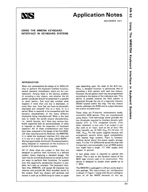
USING THE MM5704 KEYBOARDINTERFACE IN KEYBOARD SYSTEMSINTRODUCTIONWhen one contemplates the design of an MOS-LSIchip to perform the keyboard interface function,several elements immediately stand out for consideration.Among these is the obvious problemof encoding a key closure, and whether the bitpattern produced should be presented in a parallelor serial fashion. One must also consider whathappens if more than one key is depressed, ormore than two. How fast can keys be physicallydepressed and released? One at a time, or in aseries? What is required to be compatible with thedynamic characteristics of the many differentkeyboards being manufactured? What is the bestway to match the switch closure characteristics,i.e., switch bounce, etc.? How may various keyboardcapacities best be accommodated, or whatis required to allow for expansion of keyboardcapacity? All of these considerations and morehave been answered in the design of the first MOSLSI chip manufactured by National, the MM5704.It is called the keyboard interface (KI) chip andit is one of a total of five chips, called MAPS -Microprogrammable Arithmetic Processing System,being designed to implement all the functions requiredof bit serial calculation systems.All of these chips are unique in that they aredesigned to perform their functions in a definedsystem, hence implying a standard design. Yeteach may be as individualized and as varied as thereare ways to perform their functions. To explainhow this apparently paradoxical situation is possible,let's take an example. The keyboard interfacechip, MM5704, will accept 32 character keyclosures and provide 64, 9-bit encoded words inthe output. Each key closure will generate andoutput a code up to 9-bits long for lower or upperApplication NotesNOVEMBER 1971case depending upon the state of the shift key.Thus, a standard function is performed, that ofproviding a 9-bit pattern with each key closure.However, the bit pattern itself may be programmedaccording to the desires of the individual user. Thisability is possible because the 9-bit pattern isgenerated through the use of a read-only memory(ROM) located within the chip. The key closuremerely addresses the ROM and its output becomesthe custom encoded word.These chips are P-channel, enhancement mode,monolithic MaS devices. They are manufacturedusing silicon 1-0-0 technology which provides thelow thresholds required to interface directly withbipolar DTL or TTL integrated circuits. (Thislatter statement is true only if an output is notalso used as an input, such as the JlI bUS.) Thechips typically use +5 VDe (Vss, Pin 12) and -12VDe (V GG , Pin 24) power supplies because thisarrangement permits direct signal compatibilitywith bipolar logic systems. There is, however,nothing sacred about this power supply arrangement.It is the 17V differential across the chip thatis important, and conceivably in an all MaS systemone might have a single -17 VDe supply withrespect to ground.,A two phase clock is required to operate thisdevice. This is due to the dynamic nature of theMaS logic circuits used in its construction. Thisdevice is designed to accept clock speeds up to1 MHz.The MM5704 is packaged in a 24-pin cavity dual-inline package. The input-output pin configurationis shown in Figure 1 along with the pin configurationsof all the MAPS elements of this set.»zIC1INc:enjCO-t:::T(1)s:s:C1I....o~(1)< "C"oD)...Q.jr+(1)=.D)n(1)j(1)< "C"oD)..Q.en


