Trailer Air Ride Suspension Systems - Transpec
Trailer Air Ride Suspension Systems - Transpec
Trailer Air Ride Suspension Systems - Transpec
- No tags were found...

Create successful ePaper yourself
Turn your PDF publications into a flip-book with our unique Google optimized e-Paper software.
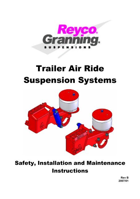
<strong>Trailer</strong> <strong>Air</strong> <strong>Ride</strong><strong>Suspension</strong> <strong>Systems</strong>Safety, Installation and MaintenanceInstructionsRev B2007/01
It is the responsibility of the installer that the installation is correctand to verify that this Installation Manual is the current version,prior to the installation of this suspension.Please contact your Reyco Distributor. If you require furtherassistance, contact:Tuthill <strong>Suspension</strong> Technologies BeijingC2 #2 AreaXin Ying Industrial ZoneEast Extension Area Beijing Economic and TechnologicalDevelopment Area (BDA)Beijing, PR China 100023北 京 经 济 技 术 开 发 区 东 区 新 城 工 业 园 二 区 C2 号 100023Phone: 861067892036 / 37 / 38Fax: 861087397151Properly installed and correctly maintained, your suspension willprovide optimum service, therefore rewarding your decision to useReyco/Granning suspensions.Should you have any further questions regarding your newsuspension, please contact us at the above address and numbers.2
TRAILER AIRRIDE SUSPENSION SYSTEMSINSTALLATION INSTRUCTIONSIMPORTANTPlease make sure this manual is accompanied by appropriate installation drawingwhich can be obtained by visiting our website at www.tuthillbeijing.com.SAFETY PROCEDURES / INFORMATION INDEXWelding & Welding Specifications 4Lifting, Overloading, Torque, <strong>Air</strong> Supply, Brake Camshafts, <strong>Air</strong> springs 5INSTALLATION INFORMATION INDEXHangers 6<strong>Air</strong> Spring Mounting Plate / Tube Crossmember 7<strong>Air</strong> Spring Mounting Plate / Channel Crossmember 8Beam / Axle Assembly 9Beam / Axle Welding Sequence (Important Welding Instructions) 10UBolt Installation & Torque Sequence 11Height Control Valve 12Alignment Procedure 13ReyAlign Details 143
SAFETY PROCEDURESSAFETY FIRSTBe sure to read and follow all installation and maintenamce procedures.WARNINGIf these procedures and specifications are not followed, damage to the suspension oraxle could occur. Failure to follow these procedures could result in an accident withconsequent injury.LIFTINGPractice safe lifting procedures. Consider size, shapeand weight of assemblies. Obtain help or the assistanceof a crane when lifting heavy assemblies. Make sure thepath of travel is clear.PARTS HANDLINGWhen handling parts, wear appropriate gloves,eyeglasses and other safety equipment to preventserious injury.WELDINGWhen welding, be sure to wear all personal protective equipment for faceand eyes, and have adequate ventilation. When welding, protect air springsfrom weld spatter and grinder sparks. Do not attach “ground” connection tothe air spring support.Welding SpecificationsTo perform the welding, the welder must be qualified for 2G position perANSI / AWS D1.194 Section 5 Part C “Welder Qualification” or equivalent.All welds must be performed in a flat and horizontal position. <strong>Suspension</strong>components and their mating parts must be free of dirt, scale, paint, grease,and moisture.Any deviation for these welding specifications must be reviewed andapproved by TST engineering in writing prior to commencement of any work.Standard ElectrodeAWS E7018 (oven dried).125 diameter 120140 amps DC electrode positive.156 diameter 120140 amps DC electrode positiveStandard WireAWS ER70S6 .045 diameter(Optional) AWS ER70S3 .045 diameterVolts26 – 30 DCRPCurrent275 325 ampsGas92% AR 8% CO2 @ 30 to 35 CFH(Optional) 90% AR 10% CO2 @ 30 to 35 CFHHelmetWeldApronWeldGlovesNOTENormally, prior to any installations at an OEM, engineering contacts between companies have been madeand all necessary information to make an installation has been exchanged. However, the following generalsteps are listed in the interest of all involved and should be included in an OEM plan to install thesuspension.Rev B2007/01
OVERLOADINGOverloading of the suspension or its components is the practice oftransporting cargos that surpass the specified vehicle’s ratings.Overloading can cause component failure, resulting in accidentsand injuries.TORQUETo comply with warranty and safety requirements, check thetorque values during predelivery inspection, after 1600 km (1,000miles) and each additional 80,000 km (50,000 miles) or annuallywhichever is first.AIR SUPPLYCheck that the supply of air pressures and flow are adequate tosupply the system. Check height control valve and linkages toensure unit is operating at the correct ride height.AIR SPRINGSThe air springs are equipped with internal bump stops for safety.However, do not operate the loaded unit on the bump stops forany extended periods of time, except to move the unit to a repairfacility.Please be sure you are matching the correct air spring to thesuspension model.5
INSTALLATION INSTRUCTIONSHANGER INSTALLATIONMarl the frame rails at the centerline locations of thehanger brackets. Crossmembers are required at allhanger and air spring locations. Crossmembers arecustomer supplied. Refer to applicable drawing forcorrect crossmember locations.Locate the hangers in the proper vertical position on theframe rails as shown on the installation drawing. Ensurethat they are square to the frame and to each other.Weld the hangers to the frame, following factory weldspecs. These are typical installation procedures andmay need to be modified due to varying frame designs.Ensure that all welding stopping points are followed asoutlined.Ensure that the hangers are braced using one of thefollowing methods:CChannel crossmember as illustratedGussets frame the hanger to the main frame crossmembers as illustratedIf the hanger has a severe offset to the frame (19 mm or 0.75 in) or more, gussets will be required. Gussets arecustomer supplied and the diagram offers a typical design. The trailer manufacturer may opt for a different gussettype.KEY POINT: The outer edge must be supported.286 mm(11.26 in.)RefOuter EdgeReinforcementAdd Gusset toCrossmemberCrossmembers are to be mountedover the Front and Rear Faces ofthe Hanger as shown.6
AIR SPRING INSTALLATION<strong>Air</strong> Spring Mounting Plate(using Tube Crossmember)NOTE: Typical examples shown on right will varyfrom trailer to trailer.Illustration showing a typical installation of the airspring mounting plate that does not require a spacer.Additional support and gusseting may be required.Gussets are customer supplied. Approximately 60%of the air spring mounting plate must be properlysupported.Illustration showing a typical installation of the airspring mounting plate that does require a spacer.Additional support and gusseting may be required.Gussets are customer supplied. Approximately 60%of the air spring mounting plate must be properlysupported.Illustration showing a typical severe offset installationof the air spring mounting plate that does or does notrequire a spacer. Additional support and gussetingmay be required. Gussets are customer supplied.Approximately 60% of the air spring mounting platemust be properly supported.Lower <strong>Air</strong> Spring Plate (ARTT only)Install the plate by fitting between the piston and thetrailing beam. Secure the air spring to the trailingbeam with fasteners supplied.7
<strong>Air</strong> Spring Mounting Plate(using Channel Crossmember)NOTE: Typical examples shown on right willvary from trailer to trailer.Illustration showing a typical installation of theair spring mounting plate that does not require aspacer. Additional support and gusseting maybe required. Gussets are customer supplied.Approximately 60% of the air spring mountingplate must be properly supported.Illustration showing a typical installation of theair spring mounting plate that does require aspacer. Additional support and gusseting maybe required. Gussets are customer supplied.Approximately 60% of the air spring mountingplate must be properly supported.Illustration showing a typical severe offsetinstallation of the air spring mounting plate thatdoes or does not require a spacer. Additionalsupport and gusseting may be required.Gussets are customer supplied. Approximately60% of the air spring mounting plate must beproperly supported.Lower <strong>Air</strong> Spring Plate (ARTT only)Install the plate by fitting between the piston andthe trailing beam. Secure the air spring to thetrailing beam with fasteners supplied.8
BEAM AND AXLE ASSEMBLY1. Locate and mark the centre line of theaxle: Ensure the beams are located at thecorrect centre line dimension calculatedfrom the axle centre line.2. Cam shaft length may be a minimum of524 mm(205/8〞).NOTE: Ancillary components should clearsuspension components by a minimum of50 mm (2〞) to allow lateral movement.Please call factory to verify yourapplication.3. Brake camshaft must be locatedaccording to suspension model and axlemanufacturer specifications. Be sure thatproper brake chamber and brakeassembly clearances are maintained.Please refer to installation drawing forcorrect positioning. Contact axlemanufacturer for proper axle weight rating.4. Review axle manufacturer’s specificationsas preheating the axle connectioncomponents may be required.5. If using cambered axle, locate and markthe upper camber line (top dead centre) ofthe axles.3. CAMSHAFT LOCATION6. Ensure that the axle makes contact withthe bottom of the axle seat as shown. Besure axle surface is clean of debris atconnection points.7. Tack weld the axle in position using four(4) 25mm (1〞) long, 6 mm (1/4〞) welds.Start at the front, then go to the rear,following the sequence shown at right.8. The contact surfaces of the beam to theaxle must be parallel to each other within0.25 degrees.C6.BA=B±0.25°A9
BEAM / AXLE WELDING SEQUENCE10
UBOLT INSTALLATIONUBOLT1. UBOLT installation and torquing should be done onlyafter completion of axle weld. Be sure to providesufficient cooling time before applying torque wrench.2. Do not apply any lubricants to the ubolts.3. Be sure that the ubolt spacer is located centrally underthe ubolt.4. Snug ubolts evenly before applying torque.5. Torque ubolts by following 3 step sequence shown.Deviation from this sequence could result in animproperly installed clamp assembly which could causedamage to the axle connection.FIRST ……….205 NM (150 ft lbs) 1*2*3*4SECOND…….410 NM (300 ft lbs) 4*3*2*1THIRD………..650 NM (480 ft lbs) 4*3*2*111
AIR CONTROLHEIGHT CONTROL VALVE1. One height control valve (HCV) is used,regardless of the number of axles. The airsprings on each side of the trailer areconnected by 9.5 mm (3/8″) minimumdiameter tubing (customer supplied). Caremust be taken to ensure the HCV ispositioned as shown on the installationdrawing for the model being installed.Tridem, HCV should be installed on thecenter axle.2. Care must be taken when installing HCV toensure correct ride height is attained.3. To set/adjust ride height, simply assemble thelinkage to the desired length to attain therequired ride height.For maximum strength, it is recommended thatthe linkage set screws 16 mm (5/8″) be placedin the end holes of both links.4. This suspension uses a height control valve(HCV) which utilizes a short delay.5. Ensure that the air springs and all valves areplumbed as shown.6. The pressure protection valve (PPV) and filterare installed between the HCV and the airreservoir.7. Using customer supplied materials, connect theHCV to all air springs using 9.5 mm (3/8″)diameter tubing. As with any pressure system,check for leaks and eliminate leakage, if present.12
ALIGNMENT1. Release the brake system and pull the trailerforwards and backwards several times in astraight line to free the suspension from bindingand tension.NOTE: This procedure must be performed on asmooth level surface.2. For best results, the use of axle extensions anda “BAZOOKA” type king pin post, or a suitableoptical alignment device are recommended.3. NOTE: Prior to commencing alignment, ensurethat the trailing beam is installed to centre line ofhanger. Align the front axle with the king pin asshown.4. Align the remaining axles to the front axle asshown.5. Torque the hanger clamp bolts if REYALIGN TMor if huck bolted, weld the alignment washers asshown.6. (REYALIGN TM feature) torque 22 mm (7/8″)alignment clamp bolt to 815 Nm (600 ft Ibs)using only a torque wrench.NOTE:Refer to page 14 for details. Run nut up veryslowly.7. Torque the adjustment shaft (REYALIGN TMfeature) clockwise to 80 Nm (60 ft lbs) or, ifHuck ® Bolt, weld the alignment washers asshown on the right.8. Optional: Weld along top of “TAB” to securealignment in position, if REYALIGN TM feature.NOTE: By removing welds carefully, youshould be able to realign up to 3 or 4 timeswith minimal or no cleaning.9. Verify that torque is correct on all fasteners.10. After initial 1,600 km (1,000 miles), thealignment should be rechecked and corrected ifnecessary; torque on the clamp nuts should alsobe checked.13
REYALIGN DETAILSCare must be taken to ensure that the REYALIGN TM option is installed correctly.HARDWARE COMPONENT LIST (per beam)Qty Description Part No.1 Pivot Bolt Q151B22240TF21 Nut Q341B22T13F22 Disc Spring Washers Q419221 Flange Washer C8030571 Pivot Bolt Sleeve C8030581 Plastic Sleeve Cover P8030552 Beam Spacers P8030591 ReyAlign Asy A8030611. Assemble the hardware as shown, ensuringcorrect installation of disc spring washers andensuring that the flange washer is installed onthe opposite side to the alignment assembly.2. To align the suspension, turn the 19 mm(3/4") adjustment shaft found on the front ofthe hanger. This will either pull the beam / axleforward or push it rearward, till you find thecorrect alignment.Beam SpacerP803059ReyAlignAssemblyA803061Flange WasherC803057Pivot BoltQ151B22240TF23. Tighten and torque the hanger clamp bolt to815 Nm (600 ft Ibs) using only a torquewrench. Run nut up very slowly.l4. Optional: Weld along top of “TAB” to securealignment in position.NOTE: By cutting welds carefully, you should be able to realign up to 3 or 4 times with minimal or nocleaning.5. Lastly, torque the 19 mm (3/4") adjustment shaft by turning clockwise to 80 Nm (60 ft Ibs).6. Verify that torque is correct on all fasteners.Hex NutQ341B22T13F2Disc Spring WasherQ41922Pivot Bolt Sleeve – C803058Plastic Sleeve Cover P803055Disc Spring WasherQ4192214