SC & TC SERIES DYNAMIC BRAKING OPTION (FOR ... - Rotor UK
SC & TC SERIES DYNAMIC BRAKING OPTION (FOR ... - Rotor UK
SC & TC SERIES DYNAMIC BRAKING OPTION (FOR ... - Rotor UK

Create successful ePaper yourself
Turn your PDF publications into a flip-book with our unique Google optimized e-Paper software.
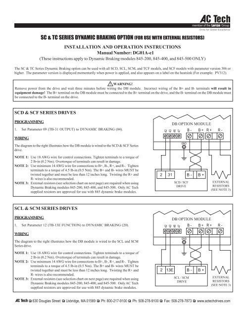
<strong>SC</strong> & <strong>TC</strong> <strong>SERIES</strong> <strong>DYNAMIC</strong> <strong>BRAKING</strong> <strong>OPTION</strong> (<strong>FOR</strong> USE WITH EXTERNAL RESISTORS)INSTALLATION AND OPERATION INSTRUCTIONSManual Number: DG01A-e1(These instructions apply to Dynamic Braking modules 845-200, 845-400, and 845-500 ONLY)The <strong>SC</strong> & <strong>TC</strong> Series Dynamic Braking option can be used with all <strong>SC</strong>D, <strong>SC</strong>L, <strong>SC</strong>M, and <strong>TC</strong>F models, and <strong>SC</strong>F models with parameter version 306 orhigher. The parameter version is displayed momentarily when power is applied, and also appears on a label on the heatsink (For example: PV312).! WARNING!Remove power from the drive and wait three minutes before wiring the DB module. Incorrect wiring of the B+ and B- terminals will result inequipment damage! The B+ terminal on the DB module must be connected to the B+ terminal on the drive, and the B- terminal on the DB module mustbe connected to the B- terminal on the drive.<strong>SC</strong>D & <strong>SC</strong>F <strong>SERIES</strong> DRIVESPROGRAMMING1. Set Parameter 09 (TB-31 OUTPUT) to <strong>DYNAMIC</strong> <strong>BRAKING</strong> (04).WIRINGThe diagram to the right illustrates how the DB module is wired to the <strong>SC</strong>D & <strong>SC</strong>F Seriesdrive.4243DB <strong>OPTION</strong> MODULE4647GNDB - B + R + R -NOTE 1: Use 18 AWG wire for control connections. Tighten terminals to a torque of2 lb-in (0.2 Nm). Overtorque of terminals can result in damage.NOTE 2: Use minimum 14 AWG wire for connections to B+, B-, R+, and R-. Tightenterminals to a torque of 4.5 lb-in (0.5 Nm). The B+ and B- wires MUST betwisted together and must be less than 12 inches long. Twisting the R+ andR- wires is also recommended.NOTE 3: External resistors (see selection chart on next page) are required when usingDynamic Braking modules 845-200, 845-400, and 845-500. Only AC Techsupplied resistors are approved for use with 845 dynamic brake modules.231<strong>SC</strong>D / <strong>SC</strong>FDRIVEB - B +EXTERNALRESISTORS(SEE NOTE 3)<strong>SC</strong>L & <strong>SC</strong>M <strong>SERIES</strong> DRIVESPROGRAMMING1. Set Parameter 12 (TB-13E FUNCTION) to <strong>DYNAMIC</strong> <strong>BRAKING</strong> (20).WIRINGThe diagram to the right illustrates how the DB module is wired to the <strong>SC</strong>L and <strong>SC</strong>MSeries drive.4243DB <strong>OPTION</strong> MODULE4647GNDB - B + R + R -NOTE 1: Use 18 AWG wire for control connections. Tighten terminals to a torque of2 lb-in (0.2 Nm). Overtorque of terminals can result in damage.NOTE 2: Use minimum 14 AWG wire for connections to B+, B-, R+, and R-. Tightenterminals to a torque of 4.5 lb-in (0.5 Nm). The B+ and B- wires MUST betwisted together and must be less than 12 inches long. Twisting the R+ andR- wires is also recommended.NOTE 3: External resistors (see selection chart on next page) are required when usingDynamic Braking modules 845-200, 845-400, and 845-500. Only AC Techsupplied resistors are approved for use with 845 dynamic brake modules.213E<strong>SC</strong>L / <strong>SC</strong>MDRIVEB - B +EXTERNALRESISTORS(SEE NOTE 3)
<strong>TC</strong>F <strong>SERIES</strong> DRIVESPROGRAMMING1. Set Parameter 06 (TB-14 OUTPUT) to DB BRAKE (11).WIRINGThe diagram to the right illustrates how the DB module is wired to the <strong>TC</strong>F drive.4243DB <strong>OPTION</strong> MODULE4647GNDB - B + R + R -NOTE 1: Use 18 AWG wire for control connections. Tighten terminals to a torque of2 lb-in (0.2 Nm). Overtorque of terminals can result in damage.NOTE 2: Use minimum 14 AWG wire for connections to B+, B-, R+, and R-. Tightenterminals to a torque of 4.5 lb-in (0.5 Nm). The B+ and B- wires MUST betwisted together and must be less than 12 inches long. Twisting the R+ and R-wires is also recommended.NOTE 3: External resistors (see selection chart below) are required when using DynamicBraking modules 845-200, 845-400, and 845-500. Only AC Tech suppliedresistors are approved for use with 845 dynamic brake modules.1411<strong>TC</strong>FDRIVEB - B +EXTERNALRESISTORS(SEE NOTE 3)MOUNTING THE <strong>DYNAMIC</strong> <strong>BRAKING</strong> MODULEThe diagram to the right illustrates how to mount the DB Module.The DB Module is compatible with the DIN Rail Mounting Kit option,or can simply be mounted to a flat surface such as an electrical panel.DIN RAILBRACKETNOTE: DO NOT mount the resistors below the drive! The resistorsgenerate heat, and must be mounted above or to the side of the drive.SELECTING EXTERNAL RESISTORSUse the chart below to select the proper external resistor assembly:DB MODULEEXTERNAL RESISTOR ASSEMBLIESHP 240 / 200 Vac 480 / 400 Vac 590 / 480 Vac0.25 - 0.5 841-001 841-002 N / A1 - 1.5 841-002 841-002 841-0012 841-003 841-003 841-0023 841-005 841-005 841-0045 841-006 841-006 841-0057.5 - 10 841-007 841-007 841-00815 - 20 841-009 841-009 841-01025 N / A 841-011 841-012SIDE VIEW4.06"2.00"FRONTVIEW4.6"NOTE: These resistor assemblies are the same as those used withthe MC Series drives. The DB Module does not include short-circuitprotection for the external resistors. If short-circuit protection isdesired, fusing must be supplied by the customer. Consult AC Tech.3.1"GND3.1"! WARNING!Hazard of electric shock! External resistors are connected to the drive's DC bus, which can reach 950 VDC. Connections to external resistors must beelectrically insulated and mechanically shielded for safety. High Voltage warning signs are also recommended.