Technical Data Lambda Transmitter LT2 Sensors and ... - lamtec
Technical Data Lambda Transmitter LT2 Sensors and ... - lamtec
Technical Data Lambda Transmitter LT2 Sensors and ... - lamtec
- No tags were found...

Create successful ePaper yourself
Turn your PDF publications into a flip-book with our unique Google optimized e-Paper software.
<strong>Technical</strong> <strong>Data</strong><strong>Lambda</strong> <strong>Transmitter</strong> <strong>LT2</strong><strong>Sensors</strong> <strong>and</strong> Systemsfor Combustion Engineering
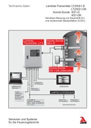
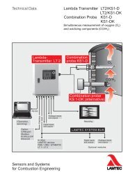
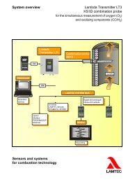
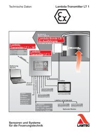
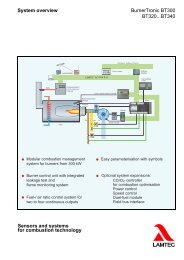
1 System Overview1 System OverviewThe <strong>LT2</strong> <strong>Lambda</strong> <strong>Transmitter</strong> is a universal, microprocessor based O 2 measuring instrumentfor the direct measurement of O 2 concentration in exhaust gases from oil <strong>and</strong> gas combustionfacilities in the superstoichiometric domain ( >1), in conjunction with the LS 2 <strong>Lambda</strong> Probe.Optionally, the KS1 Combination Probe can be activated to record combustible gas components(CO/H 2 ) - see separate publication. It is possible to set up direct coupling with the compound/firingmanagement system <strong>and</strong> ETAMATIC. This allows the implementation of animproved control procedure for optimising oil <strong>and</strong> gas combustion facilities, <strong>and</strong> for automaticcombustion system tuning to variable combustion conditions.In addition to O 2 measurement, the <strong>LT2</strong> <strong>Lambda</strong> <strong>Transmitter</strong> also offers the following functions:• Measurement of flue gas <strong>and</strong> air temperature intake, <strong>and</strong> calculation of combustion efficiency.• Detection of unburned residue (CO/H 2 ), shown as CO equivalent (CO e )• Calculation <strong>and</strong> display of CO 2 concentration• Load-dependent <strong>and</strong> fuel-specific boundary curves / limit values• O 2 -regulation• Combustion chamber pressure regulation• Field bus connectionAdvantages:• No gas purification necessary, measurement directly in humid flue gas• Settling time to 90% value (T 90 )
1 System OverviewFig. 1-1 System overview <strong>LT2</strong> <strong>Lambda</strong> <strong>Transmitter</strong>3
1 System OverviewFig. 1-2 System overview - <strong>LT2</strong> <strong>Lambda</strong> <strong>Transmitter</strong> input / output modules4
2 System Components2 System ComponentsThe O 2 measurement system is available in various versions.It consists of the following components:– <strong>LT2</strong> <strong>Lambda</strong> probe– Gas extraction device (GED)– Probe installation fitting (PIF)– Probe connection box (PCB)– <strong>LT2</strong> <strong>Lambda</strong> <strong>Transmitter</strong> in IP 54 wall-mounted housingalternatively - on mounting plate- panel installation housing including display <strong>and</strong> operating unitM measuring gas 300°C max.1 plug2 probe signal3 <strong>Lambda</strong> Probe , Type 6 50 R 10004 gas extraction device (GED)5 half-collar R11/4“, type 6 55 R 10126 probe installation fitting (PIF), Type 6 55 R 10107 probe heater8 probe connection box (PCB), Type 6 55 R 1025 (optional)9 display <strong>and</strong> operating unit, Type 6 57 R 083110 <strong>LT2</strong> <strong>Lambda</strong> <strong>Transmitter</strong> panel installation3 HE, 50 TE 173 x 310 x 280 mm (h x w x d)type 657 R 104011 <strong>LT2</strong> <strong>Lambda</strong> <strong>Transmitter</strong> in IP 54 wall-mounted housing type 657 R 1025,sheet steel, 400 x 300 x 150 mm (h x w x d) with display <strong>and</strong> operating unit13 <strong>LT2</strong> <strong>Lambda</strong> <strong>Transmitter</strong> on mounting plate350x258x132 (HxBxT) type 657 R 10305
3 Measuring Principle3 Measuring PrincipleFundamentally, the <strong>Lambda</strong> probe consists of a zirconium dioxide-ceramic electrochemicalcell. The cell operates as an electrochemical concentration chain, <strong>and</strong> generates direct voltagethat depends on the absolute temperature T <strong>and</strong> the logarithm of the O 2 concentration orthe O 2 partial pressure ratio at the inner <strong>and</strong> outer electrodes.If the outer electrode is supplied with the test gas <strong>and</strong> the inner electrode is supplied with areference gas with a known O 2 concentration e.g. air (20.96%), then assuming the temperatureis held constant, we obtain the logarithmic relationship between probe voltage U O2 <strong>and</strong>the oxygen concentration of the test gas as shown below.The characteristic curves for two different temperatures T 1 <strong>and</strong> T 2 show clearly that when usingthe voltage probe, the temperature affects the measured value in the cell's active part. Inaddition, the curves show that the probe is preferentially suitable for measuring low oxygenconcentrations, since sensitivity <strong>and</strong> accuracy increase with decreasing O 2 concentration becauseof the logarithmic relationship.Since the measurement of high O 2 concentrations is subject to high error due to the low voltagedependence, it is not possible to use, for example, air (20.96% O 2 ) to calibrate or tune theprobe. Each <strong>Lambda</strong> Probe is factory-tested under real-life conditions, in a gas-combustionsystem with an exhaust temperature of approx. 150°C / 302°F. The test protocol is enclosedwith each probe. The sensor temperature recorded in the protocol should be input into the <strong>LT2</strong>during commissioning. Calibration with test gases is not required. During operation it is possibleto check <strong>and</strong> compensate for the measured values through counter measurement.Fig. 3-1 Schematic construction of the oxygenprobeFig. 3-2 The voltage probe's equivalent electriccircuit diagram <strong>and</strong> working principle1 Gas intake 5 Reference electrode (Pt)2 Working electrode 6 Zirconium oxide ceramic3 Probe heating 7 Protective layer4 HousingFig. 3-3 The voltage probe'sworking principleFig. 3-4 <strong>Lambda</strong> Probe with GED <strong>and</strong> PIF,st<strong>and</strong>ard version6
3 Measuring PrincipleThe curve shown below demonstrates that oxygen measurements require knowledge of theproportionality factor <strong>and</strong> the probe's temperature. In practice this means adjusting the probeduring commissioning with <strong>LT2</strong> is possible simply through air voltage compensation (offsetcompensation) <strong>and</strong> entering the cell temperature which was obtained during final testing in accordancewith the test protocol enclosed with the probe (usually approx. 1000 K). The probe'slogarithmic characteristic depends on the cell’s temperature <strong>and</strong> on each probe’s curves individually.The temperature of the solid electrolyte <strong>and</strong> of the electrodes affects the probe's signal,however the probe is heated with constant current to approx. 730°C / 1346°F. Thetemperature of the measured gas <strong>and</strong> the installation site affect the cell's temperature slightly.Hence, probe temperature does not need to be measured or regulated. Individual deviationsare compensated for during commissioning by adjusting the air voltage (offset compensation)<strong>and</strong> entering the sensor temperature which was obtained during the final testing <strong>and</strong> recordedin the test protocol.The probe can only be used in a gas temperature up to 300°C / 572°F. Probe ageing in longtermoperation leads to stretching of the characteristic curve. However, this can be recognisedfrom the fact that the internal resistance increases.The probe should be replaced every 2 heating periods, no later than after 10,000 hours in operation.NOTICE!Calibration of the <strong>Lambda</strong> Probe with test gases has been ab<strong>and</strong>oned for the sake of simpleh<strong>and</strong>ling <strong>and</strong> low maintenance. The probes are measured in the factory under operationalconditions (gas combustion, exhaust gas temperature 150°C / 302°F).Individual deviation is taken into account by adjusting the air voltage (offset compensation)<strong>and</strong> entering the obtained sensor temperature obtained during commissioning.Measurement accuracy is + 10% of reading, at best 0,3 by vol.% O 2 .Fig. 3-5 Measurement <strong>and</strong> calibration diagram of the oxygen probe. The effect of temperature on theprobe's characteristic curve.7
4 Options4 Options– Display <strong>and</strong> operating unit– Measurement of flue gas <strong>and</strong> intake air temperature <strong>and</strong> calculation of combustion efficiency– Calculation <strong>and</strong> display of CO 2 concentration, fuel-referenced, computed from the measuredO 2 value <strong>and</strong> the CO 2 max. value– Load-dependent <strong>and</strong> fuel-specific limit values/boundary curves1 Boundary curve 1Fuel 1(curve 5)2 Boundary curve 2Fuel 1(curve 7)3 Burner load [%]4 Specified load [mA]Fig. 4-1 Boundary curves (factory settings), parameters adjusted to valuesbelow threshold.Possible combinations:– 2 fuels per 4 boundary curves / boundary values per fuel– 4 fuels per 2 boundary curves / boundary values per fuel– KS1 combined probe for detecting combustible components (CO/H 2 ) displayed as COequivalent (CO e )– PID controller– 1…4 analogue outputs (0/4…20 mA, 0…10 V), max. 2 floating/isolated (outputs 1 <strong>and</strong> 2),max. potential difference ±20 V, arbitrary configuration- Direct current 0/4...20 mA, burden 0...600- Direct voltage 0...10 V, burden > 10k– electrically isolated outputs– Relay module for digital outputs with 6 relays (1 change-over switch) for the output of operational <strong>and</strong> status messages, switching capability 230 V AC, 4A / 48 V DC, 3A– 1…4 analogue inputs via measurement cards, arbitrary configuration, e.g. for temperaturesensor, further pressure sensors, KS1 Combination Probe, st<strong>and</strong>ard signals etc; max. 2of these floating, common mode voltage max. ±20 V– Fieldbus-interface for:– PROFIBUS DP– Modbus– CANopen– Ethernet– Remote Display Software for PC, Windows-based– electrical casing heating8
5 <strong>Technical</strong> <strong>Data</strong>5 <strong>Technical</strong> <strong>Data</strong><strong>Technical</strong> <strong>Data</strong> <strong>Lambda</strong> <strong>Transmitter</strong> <strong>LT2</strong>Version Wall-mounted housing Panel installation Mounting plateType657 R 1025 / 657 R 1025OEM657 R 1040 657 R 1030HousingHousing in sheet steel,powder-coated3 HE / 50 TEcontrol panel housingplate in sheet steelProtection class to DIN40050IP 54IP 20Front panel IP 40IP 00Dimensions (h x w x d), mm 400x300x150 173x310x270 350x258x132Colour Grey RAL 7032 Metallic silver(alum. anodised),control elements brownWeight 10 kg 5 kg 6 kgplusdisplay <strong>and</strong> operating unit 0,5 kg --- 0,5 kgAmbient temperatureOperationTransport <strong>and</strong> storagePower supplyPower consumptionDisplay *ResolutionMeasuring accuracy(with <strong>Lambda</strong> probe)Settling time (90% time)Time for operational status to be achieved with* For <strong>LT2</strong> OEM not available-20°C...+60°C-40°C...+85°C230 V AC <strong>and</strong> 115 V AC+10% / -15%, 48 Hz...62HzTo be used only in grounded power line networks!Typically 50 VA, short-term 150 VA (probe heating-up phase)LCD graphic display 100 x 80 mm (w x h) - in <strong>LT2</strong> wall-mounted housing, optional- in panel installation case, st<strong>and</strong>ardDisplay <strong>and</strong> operating unit (version installation in a case)Display <strong>and</strong> operating unit (version panel installation for <strong>LT2</strong> on installation plate)0,1% by vol. O 2 in the range 0...18% by vol. O 2 1% by vol.O 2 in the range 18...30% by vol. O 2+/- 10% of measured value not more than +/-0,3% by vol. O 2T 90 < 15sapprox. 10 minutes after "POWER ON"9
5 <strong>Technical</strong> <strong>Data</strong><strong>Technical</strong> data <strong>Lambda</strong> <strong>Transmitter</strong> <strong>LT2</strong>Analog outputsMonitor output0...2,55 V DC, burden >10 k,
5 <strong>Technical</strong> <strong>Data</strong><strong>Technical</strong> <strong>Data</strong> <strong>Lambda</strong> <strong>Transmitter</strong> <strong>LT2</strong>Digital outputs1 st<strong>and</strong>ard + 6 optional1 relay output 0...230 V AC, 2A 0...42 V DC, 3AAccumulated error message (fault)optional:Relay card with 6 relays (1 change-over contact) Switching capability 0...230 V AC, 4A 0...48 V DC, 3AType 6 57 R 0857 (built in <strong>LT2</strong>)Type 6 60 R 0017 (spare part)Digital inputsCold-start delayConforms to the followingEuropean Directives:8 inputs - configurable (any)Factory settings: 24 V DC, referenced to instrument potentialCan be switched via jumper to floating, for external voltage source.Automatic cold-start delay 10 Min.2004/10 /EG Electromagnetic Interference2006/95/EG Low Voltage Directive11
5 <strong>Technical</strong> <strong>Data</strong><strong>Technical</strong> <strong>Data</strong> <strong>Lambda</strong> Probe LS2Protection class to DIN 40050 IP 42Measurement rangeMeasurement accuracyEffect of measured gas pressurePermissible fuelsPermissible continuous exhaustgas temperatureUseful lifeProbe output voltage0,01...21% by vol. O2Probe internal resistance R in air 20° C <strong>and</strong> 13 V heating voltageProbe voltage in air 20°C when new <strong>and</strong> 13 V heating voltageSupply voltage in plugHeat output at 13 V steady stateHeating current at 13 V steady stateIsolation resistance between heating <strong>and</strong> probe connections0...18% by vol. O 2 with restriction 0...21% by vol. O 2 10% of measured value not more than 0,3% by vol.-1,6 mV / 100 mbar changeResidue-free gaseous hydrocarbons <strong>and</strong> light heating oil 300°C / 572°F 2 years with heating oil EL <strong>and</strong> natural gas150...0 mV150 -5...-15 mV11...16 V DC; polarity cyclically reversedca. 18 Wca. 1,4 A> 30 M12
6 Connection Diagrams6 Connection DiagramsFig. 6-1 Wiring diagram <strong>Lambda</strong> <strong>Transmitter</strong> <strong>LT2</strong>13
6 Connection DiagramsFig. 6-2 Wiring diagram <strong>Lambda</strong> <strong>Transmitter</strong> <strong>LT2</strong> - inputs <strong>and</strong> probe connection33 Probe signal-34 Probe signal +35 Probe heating36 Probe heatingFig. 6-3 SAK wiring diagramtype 6 55 R 102514
6 Connection DiagramsFig. 6-4 Relay module for digital outputs(1) not available for OEM(2) Plug connector X211Fig. 6-5 25-pin plug for interface moduleInterface Module:– RS232 only in combination with Remote-Display-Software– RS422 / 485 at terminals15
7 Dimensions7 DimensionsFig. 7-1 dimensional drawingNo. Description1 gas extraction device (GED) for , length: 150 mmgas extraction device (GED) for , length:300 mmgas extraction device (GED) for , length:450 mmgas extraction device (GED) for , length: 1000 mm2 probe installation fitting (PIF) for male coupling R 1 1/4"3 <strong>Lambda</strong> ProbeFig. 7-2 <strong>LT2</strong> Wall-mounted housing dimensional diagram16
7 DimensionsFig. 7-3 Dimensional diagram: <strong>LT2</strong> panel installation top viewFig. 7-4 Dimensional diagram: <strong>LT2</strong> panel assembly dimension17
7 DimensionsFig. 7-5 Dimensional diagram: <strong>LT2</strong> panel installation front18
7 DimensionsFig. 7-6 Dimensional diagram <strong>LT2</strong> on mounting plate19
8 Ordering Information8 Ordering Information8.1 Ordering Information O2-measurementProduct / TypeOrder No.<strong>Lambda</strong> Probe LS2 with connecting cable, length 2,5 m 6 50 R 1000Gas extraction device, length 150 mm 6 55 R 1001Gas extraction device, length 300 mm 6 55 R 1002Gas extraction device, length 450 mm 6 55 R 1003Gas extraction device, length 1,000 m 6 55 R 1004probe installation fitting - male coupling R 1¼" 6 55 R 1010Half sleeve fitting, pipe screwing R 1¼" DIN 2986 for PIF 655 R 1010 6 55 R 1012Probe installation fitting - flange mounting DN32PN6 6 55 R 1040material: chromatid yellow steelFlange gasket DN32PN6, material: Graphite 3mm 6 55 P 4212Extension cable for probe-connecting-cable 2 m long 6 55 R 1006Extension cable for probe-connecting-cable, 5 m long 6 55 R 1007Extension cable for probe-connecting-cable, 10 m long 6 55 R 1008Extension cable for probe-connecting-cable, 20 m long 6 55 R 1009Probe connection box for LS2 6 55 R 1025<strong>Lambda</strong> <strong>Transmitter</strong> <strong>LT2</strong> OEM, in a wall mounting housing 300x400x150, IP66, exclusive to connect 6 57 R 1020the ETAMATIC via LAMTEC SYSTEM BUS (LSB) for the O 2 -regulation without LCD-Display <strong>and</strong> manualcontrol panel, without analogue outputAttention: A refitting of the LCD-Display <strong>and</strong> manual control panel is not possible!<strong>Lambda</strong> <strong>Transmitter</strong> <strong>LT2</strong>, in a wall mounting housing 300x400x150, IP54, without LCD-Display <strong>and</strong> 6 57 R 1025manual control panel, analogue output 0/4-20mA or 0/2-10V<strong>Lambda</strong> <strong>Transmitter</strong> <strong>LT2</strong>, on mounting plate, prepare for control cabinet without LCD-Display <strong>and</strong> manualcontrol panel, analogue output 0/4-20mA or 0/2-10V6 57 R 1030<strong>Lambda</strong> <strong>Transmitter</strong> <strong>LT2</strong>, prepares for panel mounting cabinet, analogue output 0/4-20mA or 0/2-10V 6 57 R 10408.2 Detection of Combustibles (CO/H) - OptionProduct / TypeOrder no.Combination Probe KS1 with PTFE-connecting cable (up to 250°C), length: 2 m6 56 R 0000 TCombination Probe KS1 with glass-silk insulated connecting cable (up to 400°C), length: 1,5 m 6 56 R 0001 TProbe connection box for KS1 6 56 R 1025<strong>Lambda</strong> <strong>Transmitter</strong> <strong>LT2</strong>, in wall-mounting housing 300x400x150, IP54, to connect the Combination 6 57 R 1025KS1Probe KS1 directly, without display <strong>and</strong> operating unit, analogue output 0/4-20mA or 0/2-10VSoftware upgrade for <strong>LT2</strong>/<strong>LT2</strong> for CO-detection with the Combination Probe KS1, incl. remote-connection6 57 R 0601to one LT (master) with O 2 -measurementSoftware upgrade for <strong>LT2</strong>/<strong>LT2</strong> for CO-control by the Combination Probe KS1, incl. remote-connection 6 57 R 0602to one LT (master) with O 2 -measurement only in combination with FMS/ETAMATIC)20
8 Ordering Information8.3 OptionsProduct / TypeOrder No:Display <strong>and</strong> operating unit (design: housing for <strong>LT2</strong> in wall-mounted housing) 6 57 R 0831Display <strong>and</strong> operating unit, cable length 1,5m (design: panel installation for <strong>LT2</strong> on mounting plate) 6 57 R 0831TCalculation of the combustion efficiency, incl. 2 input cards for PT100 temperature sensors 6 57 R 0895Temperature input for PT 100, e.g. to measure flue gas temperature 6 57 R 0890Temperature sensor PT-100, 250 mm length, -50°C...+400°C 6 57 R 0891Temperature sensor PT-100, 150 mm length, -50°C...+400°C 6 57 R 0897Calculation of the CO 2 concentration 6 57 R 0910Integrated PID-controller for O 2 control, temperature control, pressure control etc. 6 57 R 1120Firing rate <strong>and</strong> fuel specific related limit curves/limit values, incl. analogue input PCB-card (alternatively:6 57 R 0922current, potentiometer or LSB) <strong>and</strong> 1 relay module 657 R 0017Relay module R 0017 with 6 relays for output of operating <strong>and</strong> status, mounted in <strong>LT2</strong> 6 57 R 0857Analogue output 0/4...20 mA, 0...10 V 6 57 R 0050Analogue output 0/4...20 mA, 0...10 V isolated, +20 V max. potential difference (only output 1 + 2) 6 57 R 0051Isolated analogue output 1, +20 V max. potential difference VMS /FMS 4...20 mA 0...25% by vol.O 2 6 57 R 0054REGAnalogue input 0/4...20mA 6 63 R 6001Analogue input 0/4...20mA with feeding 24V DC for transmitter 6 63 P 6002Analogue input 0/2...10V 657P 6000Analogue input for LT1 / <strong>LT2</strong> potentiometer 1...5 k 657P 6005BUS-Interface PCB for PROFIBUS DP6 63 R 0401LTBUS-interface PCB for CANopen6 63 R 0402LTBUS-Interface PCB for Modbus6 63 R 0403LTBUS-Interface PCB for Ethernet (Modbus TCP)6 63 R 0406LTRemote-Display-Software incl. interface-module RS 232 6 57 R 1101Interface-module RS 422/485 on terminals 6 63 P 0503Electric casing heating 230 V, 120 W, mounted in <strong>LT2</strong>, switching point > +15 °C 6 57 R 036721
8 Ordering Information8.4 Ordering ExamplesO2-Measurement <strong>LT2</strong> / LS2-KV – fully automated calibration in wall mounting housing IP 54Product/ TypeOrder-No.1 <strong>Lambda</strong> Probe LS2 6 50 R 10001 Gas extraction device, length 300 mm 6 55 R 10021 Probe installation fitting, pipe support 1/4" 6 55 R 10101 <strong>LT2</strong> <strong>Lambda</strong> <strong>Transmitter</strong> in wall-mounting housing IP54 6 57 R 10251 Display <strong>and</strong> operating unit 6 57 R 08311 Relay module for operational, status <strong>and</strong> limit value messages outputs 6 57 R 0857O2-Measurement <strong>LT2</strong>/ LS2 for measuring gas temperatures up to 300 °C /572°F, wall mounting housing IP 54 in combination with VMS / FMS / ETAMATICProduct / TypeOrder-No.1 <strong>Lambda</strong> Probe LS2 6 50 R 10001 Gas extraction device, length 300 mm 6 55 R 10021 Probe installation fitting, pipe support 1/4" 6 55 R 10101 <strong>LT2</strong> <strong>Lambda</strong> <strong>Transmitter</strong> in wall-mounted housing IP5 6 57 R 10251 Isolated analogue output 1, configured for connecting VMS / FMS 6 57 R 0054REGO2- Measuring <strong>LT2</strong> / LS 2 panel installation housing 3HE/50TEProduct / TypeOrder-No.1 <strong>Lambda</strong> Probe LS2 6 50 R 10001 Gas extraction device (GED), length 150 mm 6 55 R 10011 Probe installation fitting (PIF), pipe support R 1 ¼ " 6 55 R 10101 Probe junction box (SAK) 6 55 R 10251 <strong>Lambda</strong> <strong>Transmitter</strong> <strong>LT2</strong> (prepares for panel mounting cabinet) incl. operating keypad <strong>and</strong> display 6 57 R 1040O2- Measurement in combination with the detection of combustibles (CO/H), indicated as CO-equivalent (COe) [ppm]Product / TypeOrder-No.1 <strong>Lambda</strong> Probe LS2 6 50 R 10001 Combination Probe KS 1 with PTFE-connection cable (to 200 °C), length 2 m 6 56 R 0000T2 Flue gas intake (GED), length 300 mm 6 55 R 10022 Probe installation fitting (PIF), pipe support R 1 ¼ " 6 55 R 10101 Probe connection box (SAK) 6 55 R 10251 <strong>Lambda</strong> <strong>Transmitter</strong> <strong>LT2</strong> in wall mounting cabinet IP 54 KS1 6 57 R 1025 / KS11 <strong>Lambda</strong> <strong>Transmitter</strong> <strong>LT2</strong> in wall mounting cabinet IP 54 6 57 R 10251 Software-extension for LT 1 / <strong>LT2</strong> for CO-detection with the combination-probe KS1 incl.REMOTE connection to LT (master) with O 2 -measurement6 57 R 060122
8 Ordering Information23
LAMTEC Meß- und Regeltechnikfür Feuerungen GmbH & Co. KGWiesenstraße 6D-69190 WalldorfTelefon: +49 (0) 6227 6052-0Telefax: +49 (0) 6227 6052-57Internet: www.<strong>lamtec</strong>.deE-mail: info@<strong>lamtec</strong>.deLAMTEC Leipzig GmbH & Co. KGSchlesierstraße 55D-04299 LeipzigTelefon +49 (0) 341 863294-00Telefax +49 (0) 341 863294-10Presented by:Print no. DLT6063-11-cEN-130Printed in Germany