Fixed displacement axial piston pump type K60N - Hidracomp
Fixed displacement axial piston pump type K60N - Hidracomp
Fixed displacement axial piston pump type K60N - Hidracomp
- No tags were found...

Create successful ePaper yourself
Turn your PDF publications into a flip-book with our unique Google optimized e-Paper software.
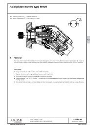
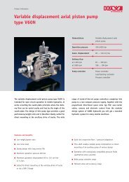
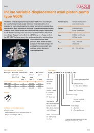
<strong>Fixed</strong> <strong>displacement</strong> <strong>axial</strong> <strong>piston</strong> <strong>pump</strong> <strong>type</strong> <strong>K60N</strong>Max. operating pressure p maxMax. geom. <strong>displacement</strong> V g= 400 bar (5500 psi)= 108 ccm/rev. (61 cu in)1.21. GeneralThe fixed <strong>displacement</strong> <strong>axial</strong> <strong>piston</strong> <strong>pump</strong> <strong>type</strong> K 60N (bent axis design) is especially suited for demanding, high-duty service.The <strong>pump</strong> covers the whole <strong>displacement</strong> range up to 108 cm 3 /rev. The <strong>pump</strong> has been developed with modern styling and designto satisfy market demand as to high flow performance, high pressures with high effciency and very small dimensions. The <strong>pump</strong> isavailable both to DIN and SAE standards and can be mounted either directly at the gear box or via a drive shaft. If necessary it canalso be augmented with a by-pass valve.The <strong>pump</strong>s have the following advantages:' High speed rating' Low noise level' Smooth running and long bearing life' External fluid leaks are eliminated by using O-rings at all sealing surfaces' Optional by-pass valve© 2001 by HAWE HydraulikHAWE HYDRAULIK SESTREITFELDSTR. 25 • 81673 MÜNCHEND 7960 K<strong>Fixed</strong> displasment<strong>axial</strong> <strong>piston</strong> <strong>pump</strong>March 2001-02
D 7960 K page 22. Available versions, main dataOrder example: <strong>K60N</strong> - 064 L SC N<strong>K60N</strong> - 108 R D N - S-F12 - A45/76Basic <strong>type</strong>Nom. size (table 1)Direction of rotation:R = clockwiseL = counter clockwiseTable 1: Nom. sizeSuction connections, see table 2By-pass-valve: S-F12 = NO-<strong>type</strong>, solenoid voltage 12V DCS-F24 = NO-<strong>type</strong>, solenoid voltage 24V DCShaft seals: N = NBR (Nitril)V = FKM (Viton)Shaft design and mounting flange:D = Spline shaft (DIN ISO 14), with flange ISO 7653-1985SB = Spline shaft with flange SAE-B (nom. size 025, 034, 047, 064)SC = Spline shaft with flange SAE-C (nom. size 047, 064, 084, 108)Coding 012 017 025 034 047 064 084 108984 2 ) 9108 2 )Geom. <strong>displacement</strong> (ccm/rev.) 12.6 17.0 25.4 34.2 47.1 63.5 83.5 108.0Flow (theor.)(lpm)at 500 rpm 5.8 7.9 12.5 17.0 23.5 31.5 41.5 54.01000 rpm 12.0 16.2 25.0 34.0 47.0 63.5 83.5 108.01500 rpm 18.3 24.7 37.5 51.0 70.5 95.5 125.0 162.0Speed intermittent 1 ) n max (rpm) 3000 3000 3000 3000 2500 2500 2000 / 2000 /2200 2300continuous n nom (rpm) 2300 2300 2300 2300 1900 1900 1500 / 1500 /1600 1900Operating pressure p max (bar) 400 400 400 400 400 400 400 400Mass (weight) (kg) 8.1 8.1 8.1 8.1 11.7 11.7 17.0 17.0Tare-weight torque (Nm) 6.9 6.9 7.4 7.4 13 13 21 211) Intermittent operation, duty cycle of max.10 sec./min2) Pump <strong>type</strong>s <strong>K60N</strong>-984 resp. -9108 are specially designed highspeed-versions, the back cover can not be turned to reverse thedirection of rotation.Main data by-pass valveTable 2: Suction connectionsOrder examples:K 60 N - 084 RDN - A6K 60 N - 025 LDN - A 45 / 38Nom. sizeGeometric shapestraight45°90°threadSizeNom. sizeQ max (l/min)A00/..A45/..A90/..A.012, 017,025, 034,047, 064323842507590''--''-'----50125'''-Coding S - F12 S - F24Nom. voltage 12 V DC 24 V DCNom. power 12 W 12 WProtection class IP 66 IP 66084, 984,108, 91085384250907590125-'-'--''-'-'' (G1)---Nom. size 012 to 064 084 to 108Mass 2.0 kg 2.4 kg(weight)64766160190125''-''-''---' (G1 1/4)G.... & BSPP
D 7960 K page 33. Additional versions3.1. GeneralCalculation:Flow rate Torque PowerVg ⋅ n ⋅ η v1,59 ⋅ Vg⋅ ∆p2π⋅ M ⋅ n M ⋅ n Q ⋅ ∆pQ = (lpm) M = (Nm)P == = (kW)1000100 ⋅ ηmh60000 9549 600 ⋅η tV g = Geom. dicplacement (ccm/rev.)|p = Diff. pressure (bar)n = Speed (rpm)η v = Volumetric efficiencyη mh = Mechanical-hydraulic efficiencyη t = Total efficiency (η t = η . v η mh )Working principle<strong>Fixed</strong> <strong>displacement</strong> <strong>axial</strong> <strong>piston</strong> <strong>pump</strong> acc. to bent-axis principleInstallationP.T.O. of truck gear boxes (flange ISO 7653.1985 for trucks) or flange mounting (flange SAE)Direction of rotationAnyChanging of rotating direction Rotating of end cover (see dimensional drawing) by 180°(not possible with <strong>type</strong> <strong>K60N</strong>-984 resp. <strong>K60N</strong>-9108)max. bolt torque:Nom. size 012...064: 70 NmNom. size 084, 108: 100 NmMounting positionOptionalPressure fluid Hydraulic fluid (DIN 51524 table 2 and 3); ISO VG 10 to 68 (DIN 51519)Viscosity range: min. 10; max. 700 mm 2 /s,Optimal operation range: 20...40 mm 2 /sAlso suitable are biodegradable pressure fluids of the <strong>type</strong> HEES (synth. Ester) at operationtemperatures up to +70°C.TemperatureAmbient: -40 ... +60°CFluid: -25...+80°C, pay attention to the viscosity range!Start temperature down to -40°C are allowable (Pay attention to the viscosity range during start-up!),as long as the operation temperature during consequent running is at least 20K (Kelvin) higher.Filtration Min. conforming ISO standard 4406 code 16/13.Start-upSuction pipe should be as big as possible (see also selection of suction connections intable 2). Flexible hoses should be fixed by two strong hose straps. Suction filter should not beassembled.All hydraulic lines should be flushed with appropriate hydraulic fluid before start-up. The <strong>pump</strong>case should then be bled via the uppermost drain port.Note: The surroundings should be clean while filling the <strong>pump</strong>. Check the rotation direction ofdrive and <strong>pump</strong> prior to initial operation.At start-up and during the first few minutes of the operation the pressure relief valve should beset to 50 bar (700 psi) or less.
D 7960 K page 44. Unit dimensionsAll dimensions in mm, subject to change without notice !K 60 N - 12...108.DK 60 N - 025...064.SBK 60 N - 047...108.SCKB8x32x34.9 DIN ISO 1413 T 7/8”14 T 11/4”KSuction connection#13 (at flanges acc.ISO 7653)#14.3 (at flangesSAE-B and SAE-C)G = G 3/4 (BSPP) Nom. size 012, 017, 025, 034, 047, 064= G 1 (BSPP) Nom. size 084, 984, 108, 9108Nom. sizeLHAA 1B 1 )C#D 1 )El 1 )a 11)a 21)M 1 )1217253420220220220297979797979797978989898980/—/—80/—/—80/89.8/—80/89.8/—8787878780/—/—80/—/—80/101.6/—80/101.6/—9999999955/—/—55/—/—55/41/—55/41/—97/—/—97/—/—97/101/—97/101/—11211211211212/—/—12/—/—12/—/—12/—/—4764228228109109106106999980/89.8/114.580/89.8/114.595.595.580/101.6/12780/101.6/12710910955/41/5655/41/56113/117/119113/117/11913013012/—/—12/—/—8410825925912612612312311511580/—/114.580/—/114.511511580/—/12780/—/12712612655/—/5655/—/56123/—/128123/—/12814714712/—/—12/—/—1) Dimensions of flanges acc. ISO 7653-1985 / flanges SAE-B / flanges SAE-CT = G 1/2 (BSPP) Nom. size 012 ... 064= G 3/4 (BSPP) Nom. size 084 ... 9108M= G 1/8 (BSPP)012, 017, 025 084, 984034, 047, 064 108, 9108G = G 3/4 (BSPP) Nom. size 012 ... 064G 1 (BSPP) Nom. size 084 ... 9108U 25 28O 31 31P 36 42Q 100 116R 110 127S 45 41Suction connectionsA00/...A45/..A90/...A5 or A6N = Nom. size acc. table 2, page 2