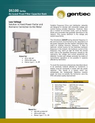
FT100-LV Auto-Detuned Filter banks - Gentec
FT100-LV Auto-Detuned Filter banks - Gentec
FT100-LV Auto-Detuned Filter banks - Gentec
- No tags were found...

You also want an ePaper? Increase the reach of your titles
YUMPU automatically turns print PDFs into web optimized ePapers that Google loves.
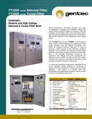
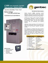
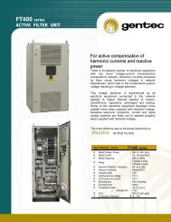
<strong>FT100</strong> series <strong>Detuned</strong> <strong>Filter</strong> Bank<strong>Auto</strong>matic Power Factor correctionand <strong>Filter</strong> BanksThe Power Quality SolutionPower transmission and distribution systems aredesigned to operate with sinusoidal voltage andcurrent having constant frequency. When nonlinearloads-such as thyristor drives and converters areconnected to the system, harmonics are generated,which causes voltage and current distortion.Capacitor capacitance and network inductance mayform a parallel resonant circuit where harmoniccurrents may reach as high as 20 times the normallevel. Should the tuned frequency of the resonantcircuit match an existing harmonic frequency, thecurrent distortion caused by resonance leads tofurther voltage distortion? This is why power factorcorrection can be affected by harmonic networkcontent.In systems where harmonics are present, powerfactor correction should be done by means of detunedfilters. These consist of capacitors and reactorsconnected in series, and are capable of compensatingreactive power at fundamental frequency withoutamplifying the harmonics.6 to 20 Unit Assemblies‣ 20 to 1200 kVAR‣ 208 to 600 Volts‣ Nema-1, 12, 3R & 4XTECHNICAL DATA - <strong>FT100</strong> seriesRated Voltage / Phase 208 TO 600 Volts / 3 phasesRated Frequency 50Hz or 60HzRated Power20 to 1200 kVAR / unitTuned Frequency7% or 12.6% (other tune frequencyon requestPower Factor Controller N12 or NC12 12 stepsInsulation level5 kVPower losses0.4 w/kVARContinuous over-voltage 110 %Continuous over-current 135 %Mounting typeFloor mountingEnclosure typeIndoor , outdoorTemperature class -40 `C to 55`Co Average 24h : + 45`CColorASA 61 (light grey)Construction Standard UL, CSA, IEC
POWER FACTOR CORRECTION IN THEPRESENCE OF HARMONICS<strong>Gentec</strong> <strong>FT100</strong> <strong>Detuned</strong> filters are designedto be used for power factor correction insystems where harmonics are generated.Each step of a detuned filter consists of acapacitor and a reactor connected in series.These components form a series resonantcircuit tuned at a frequency below the lowestharmonic frequency present in the system,normally the 5 th (300Hz).Below the tuned frequency of the resonantcircuit, for example at fundamental frequency(60Hz), the detuned filter is capacitive,generating reactive power. Above the tunedfrequency the detuned filter is inductive, whichmeans that it cannot amplify any commonharmonics, including the 5 th , 7 th and 11 th . Adetuned filter also removes lower orderharmonics from the system to some extent.1324As in conventional capacitor <strong>banks</strong>, the stepsare switched on and off by power factorcontrollers according to the demand of reactivepower.1. DSHI CAPACITORS2. FILTER REACTOR3. CONTROL DEVICES4. SWITCHING DEVICESP.Q. ManagerPage 2 of 4
‣ Technical Data <strong>FT100</strong> seriesStandard Features and Options : 4 Units Ass. 6 Units Ass. 12 Units Ass.Enclosure floor mounted c/w lifting ring ( Type 1, 2, 3R, 4X ) 1, 2, 3R, 12, 4X 1, 2, 3R, 12, 4X 1, 2, 3R, 12, 4XThree points lockable door handle • • •ASA 61 Grey ( other color on request ) • • •Top Cable entry ( Bottom entry on request ) • • •Capacitors space / KVAR max / Unit (Custom Staging Ratios ) 4 / 100 kVAR 6 / 100 kVAR 12 / 100 kVARIncoming silver Flashed Copper Bus 30 kV BIL c/w mechanical lugs • • •Power and Control wires T90 / T105 T90 / T105 T90 / T105DSHI Capacitor ( Heavy Duty type on request ) • • •Current limiting fuses HRC type ____ Amp. 200 ka • • •Magnetic Contactor c/w special switching devices • • •<strong>Detuned</strong> reactor c/w thermal detection device • • •Power Factor Controller (On / Off switches ) 6 steps 6 & 12 steps 12 stepsControl & Potential Transformer c/w GFI breaker*, CT Shorting • • •Thermostatic ventilation system • • •Optional (s)Current Transformer ( Split core type ) O O OMain Breaker or Fuses Disconnect O O OBlown fuses indicating light c/w push bottom test O O OMain current metering c/w Ammeter and phase selector O O OElectric Door interlock O O OKirk Key system interlock with the remote main breaker O O OSpecial Metering Arrangement O O OGround switch interlocked with doors and main supply O O O‣ Technical Application• Standard O = OptionalIf harmonic filters are being considered only for the purpose of power factor correction, then a de-tuned filter bank is the best choice. This filterwill do little for removing any harmonic distortion present on the system but will allow the installation of a large capacitor bank without anyadverse system interactions. De-tuned filter <strong>banks</strong> are less costly an are more reliable than partially de-tuned and tuned filter <strong>banks</strong>. The antiresonantfrequency should be considered to assure that it does not fall near the 3rd harmonic.• <strong>Detuned</strong> filtersWhen the resonant frequency of the series resonant filter circuit is tuned to a frequency lower than the harmonic occurring in thesystem, the filter circuit is termed as detuned filter. The philosophy of the detuned filters would be clear from the following example.The harmonics that would be generated are 5th,7th, 11th and 13th and so on. The lowest harmonic frequency which would occur inthe system is the fifth harmonic i.e. 300 Hz. If the series resonant circuit is tuned to a frequency of 245 Hz, then at all the harmonicfrequencies the filter acts as an inductive component and the possibility of resonance at the fifth harmonic is eliminated.The impedance offered to the 5th harmonic signal is less than the capacitor alone. This means that the series resonant filter willabsorb the 5th harmonic to a certain extent.The reactor to capacitance ratio p(%) reflects the ratio of reactor reactance to capacitor reactance at fundamental frequency. Theresonant frequency of the series resonant filter circuit is indicated indirectly by p. The following table shows a comparison forvarious reactor/ capacitor combinations at fundamental frequency of 60 Hz.ResonanceFrequencyFrRelativeResonance227 3.8 7.0245 4.1 6.0252 4.2 5.67282 4.7 4.52288 4.8 4.33300 5.0 4.0Reactor/CapacitorFactor : pPage 3 of 4