w65c816s Microprocessor Data Sheet.pdf
w65c816s Microprocessor Data Sheet.pdf
w65c816s Microprocessor Data Sheet.pdf

Create successful ePaper yourself
Turn your PDF publications into a flip-book with our unique Google optimized e-Paper software.
The Western Design Center, Inc.Updated June 14, 2004W65C816S <strong>Data</strong> <strong>Sheet</strong>W65C816S<strong>Microprocessor</strong>DATA SHEET© The Western Design Center, Inc., 2004. All rights reservedWDC
The Western Design Center, Inc.W65C816S <strong>Data</strong> <strong>Sheet</strong>WDC reserves the right to make changes at any time without notice in order to improve design and supplythe best possible product. Information contained herein is provided gratuitously and without liability, toany user. Reasonable efforts have been made to verify accuracy of the information but no guaranteewhatsoever is given as to the accuracy or as to its applicability to particular uses. In every instance, itmust be the responsibility of the user to determine the suitability of the products for each application.WDC products are not authorized for use as critical components in life support devices or systems.Nothing contained herein shall be construed as a recommendation to use any product in violation ofexisting patents or other rights of third parties. The sale of any WDC product is subject to all WDCTerms and Conditions of Sales and Sales Policies, copies of which are available upon request.Copyright (C) 1981-2004 by The Western Design Center, Inc. All rights reserved, including the right ofreproduction in whole or in part in any form.The Western Design Center W65C816S 2
The Western Design Center, Inc.W65C816S <strong>Data</strong> <strong>Sheet</strong>TABLE OF CONTENTS1 INTRODUCTION ...........................................................................................................................72 W65C816S FUNCTIONAL DESCRIPTION.................................................................................82.1 Instruction Register (IR).......................................................................................................... 82.2 Timing Control Unit (TCU)...................................................................................................... 82.3 Arithmetic and Logic Unit (ALU)............................................................................................. 82.4 Internal Registers (Refer to Programming Model Table 2-2) ................................................... 82.5 Accumulator (A)....................................................................................................................... 82.6 <strong>Data</strong> Bank Register (DBR)....................................................................................................... 92.7 Direct (D) ................................................................................................................................. 92.8 Index (X and Y)........................................................................................................................ 92.9 Processor Status Register (P).................................................................................................... 92.10 Program Bank Register (PBR)................................................................................................. 92.11 Program Counter (PC)........................................................................................................... 102.12 Stack Pointer (S) .................................................................................................................... 103 PIN FUNCTION DESCRIPTION...............................................................................................133.1 Abort (ABORTB)................................................................................................................... 163.2 Address Bus (A0-A15)............................................................................................................ 163.3 Bus Enable (BE)..................................................................................................................... 163.4 <strong>Data</strong>/Bank Address Bus (D0-D7)............................................................................................ 163.5 Emulation Status (E).............................................................................................................. 173.6 Interrupt Request (IRQB)...................................................................................................... 173.7 Memory Lock (MLB)............................................................................................................. 173.8 Memory/Index Select Status (MX) ......................................................................................... 173.9 Non-Maskable Interrupt (NMIB)........................................................................................... 183.10 Phase 2 In (PHI2)................................................................................................................... 183.11 Read/Write (RWB)................................................................................................................. 183.12 Ready (RDY).......................................................................................................................... 183.13 Reset (RESB).......................................................................................................................... 193.14 Valid <strong>Data</strong> Address (VDA) and Valid Program Address (VPA)............................................. 193.15 VDD and VSS......................................................................................................................... 193.16 Vector Pull (VPB)................................................................................................................... 194 ADDRESSING MODES...............................................................................................................204.1 Reset and Interrupt Vectors ................................................................................................... 204.2 Stack ...................................................................................................................................... 204.3 Direct ..................................................................................................................................... 204.4 Program Address Space ......................................................................................................... 204.5 <strong>Data</strong> Address Space................................................................................................................ 20Absolute-a .........................................................................................................................................................................................21Absolute Indexed Indirect-(a,x) .....................................................................................................................................................21Absolute Indexed with X-a,x .........................................................................................................................................................21Absolute Indexed with Y-a,y .........................................................................................................................................................21Absolute Indirect-(a)........................................................................................................................................................................22Absolute Long Indexed With X-al,x.............................................................................................................................................22Absolute Long-al..............................................................................................................................................................................22Accumulator-A .................................................................................................................................................................................22The Western Design Center W65C816S 3
The Western Design Center, Inc.W65C816S <strong>Data</strong> <strong>Sheet</strong>Block Move-xyc ...............................................................................................................................................................................22Direct Indexed Indirect-(d,x)..........................................................................................................................................................23Direct Indexed with X-d,x..............................................................................................................................................................23Direct Indexed with Y-d,y ..............................................................................................................................................................23Direct Indirect Indexed-(d),y..........................................................................................................................................................24Direct Indirect Long Indexed-[d],y ...............................................................................................................................................24Direct Indirect Long-[d]..................................................................................................................................................................24Direct Indirect-(d) ............................................................................................................................................................................25Direct-d ..............................................................................................................................................................................................25Immediate-# ......................................................................................................................................................................................25Implied-i ............................................................................................................................................................................................25Program Counter Relative Long-rl................................................................................................................................................25Program Counter Relative-r ...........................................................................................................................................................26Stack-s ................................................................................................................................................................................................26Stack Relative-d,s.............................................................................................................................................................................26Stack Relative Indirect Indexed-(d,s),y ........................................................................................................................................265 TIMING, AC AND DC CHARACTERISTICS............................................................................285.1 Absolute Maximum Ratings ................................................................................................... 285.2 DC Characteristics TA = -40°C to +85°C.............................................................................. 296 OPERATION TABLES.................................................................................................................327 RECOMMENDED W65C816S ASSEMBLER SYNTAX STANDARDS...................................527.1 Directives ............................................................................................................................... 527.2 Comments .............................................................................................................................. 527.3 The Source Line ..................................................................................................................... 527.3.1 The Label Field.................................................................................................................................................................527.3.2 The Operation Code Field ..............................................................................................................................................527.3.3 The Operand Field ...........................................................................................................................................................537.3.4 Comment Field .................................................................................................................................................................558 Caveats...........................................................................................................................................568.1 Stack Addressing.................................................................................................................... 578.2 Direct Addressing................................................................................................................... 578.3 Absolute Indexed Addressing ................................................................................................. 578.4 ABORTB Input...................................................................................................................... 578.5 VDA and VPA Valid Memory Address Output Signals .......................................................... 578.6 DB/BA operation when RDY is Pulled Low............................................................................ 588.7 MX Output............................................................................................................................. 588.8 All OpCodes Function in All Modes of Operation.................................................................. 588.9 Indirect Jumps ....................................................................................................................... 588.10 Switching Modes .................................................................................................................... 588.11 How Interrupts Affect the Program Bank and the <strong>Data</strong> Bank Registers ................................ 588.12 Binary Mode .......................................................................................................................... 598.13 WAI Instruction..................................................................................................................... 598.14 The STP Instruction............................................................................................................... 598.15 COP Signatures...................................................................................................................... 598.16 WDM OpCode Use................................................................................................................. 598.17 RDY Pulled During Write ...................................................................................................... 598.18 MVN and MVP Affects on the <strong>Data</strong> Bank Register................................................................ 598.19 Interrupt Priorities................................................................................................................. 608.20 Transfers from 8-Bit to 16-Bit, or 16-Bit to 8-Bit Registers .................................................... 60The Western Design Center W65C816S 4
The Western Design Center, Inc.W65C816S <strong>Data</strong> <strong>Sheet</strong>8.21 Stack Transfers ...................................................................................................................... 608.22 BRK Instruction..................................................................................................................... 608.23 Accumulator switching from 8 bit to 16 bit ............................................................................ 609 HARD CORE MODEL.................................................................................................................619.1 W65C816 Core Information................................................................................................... 6110 SOFT CORE RTL MODEL......................................................................................................6110.1 W65C816 Synthesizable RTL-Code in Verilog HDL.............................................................. 6111 ORDERING INFORMATION .................................................................................................62The Western Design Center W65C816S 5
The Western Design Center, Inc.W65C816S <strong>Data</strong> <strong>Sheet</strong>Table of TablesTable 2-1 W65C816S <strong>Microprocessor</strong> Programming Model......................................................................12Table 3-1 Pin Function Table .........................................................................................................................16Table 4-1 Addressing Mode Summary..........................................................................................................27Table 5-1 Absolute Maximum Ratings ..........................................................................................................28Table 5-2 DC Characteristics .........................................................................................................................29Table 5-3 IDD vs. VDD ...................................................................................................................................29Table 5- 4 F Max vs. VDD...............................................................................................................................29Table 5-4 W65C816S AC Characteristics .....................................................................................................30Table 6-1 W65C816S Instruction Set-Alphabetical Sequence ....................................................................32Table 6-2 Emulation Mode Vector Locations (8-bit Mode).........................................................................34Table 6-3 Native Mode Vector Locations (16-bit Mode) .............................................................................34Table 6-4 OpCode Matrix...............................................................................................................................35Table 6-5 Operation, Operation Codes, and Status Register (continued on following 4 pages)...............36Table 6-6 Addressing Mode Symbol Table ...................................................................................................41Table 6-7 Instruction Operation (continued on following 6 pages)............................................................42Table 6-8 Abbreviations ..................................................................................................................................50Table 7-1 Alternate Mnemonics .....................................................................................................................53Table 7-2 Address Mode Formats..................................................................................................................54Table 7-3 Byte Selection Operator.................................................................................................................55Table 8-1 Caveats ............................................................................................................................................56Table of FiguresFigure 2-1 W65C816S Internal Architecture Simplified Block Diagram..................................................11Figure 3-1 W65C816S 44 Pin PLCC Pinout .................................................................................................13Figure 3-2 W65C816S 40 Pin PDIP Pinout ...................................................................................................14Figure 3-3 W65C816S 44 PIN QFP Pinout ...................................................................................................15Figure 5-1 General Timing Diagram.............................................................................................................31Figure 6-1 Bank Address Latching Circuit ....................................................................................................51The Western Design Center W65C816S 6
The Western Design Center, Inc.1 INTRODUCTIONW65C816S <strong>Data</strong> <strong>Sheet</strong>The W65C816S is a low power cost sensitive 16-bit microprocessor. The variable length instruction set and manuallyoptimized core size makes the W65C816S an excellent choice for low power System-on-Chip (SoC) designs. The Verilog RTLmodel is available for ASIC design flows. WDC, a Fabless Semiconductor Company, provides packaged chips for evaluationor volume production. To aid in system development, WDC provides a Development System that includes a W65C816DBDeveloper Board, an In-Circuit Emulator (ICE) and the W65cSDS Software Development System, seewww.westerndesigncenter.com for more information.The WDC W65C816S is a fully static CMOS 16-bit microprocessor featuring software compatibility* with the 8-bit NMOSand CMOS 6500-series predecessors. The W65C816S extends addressing to a full 16 megabytes. These devices offer themany advantages of CMOS technology, including increased noise immunity, higher reliability, and greatly reduced powerrequirements. A software switch determines whether the processor is in the 8-bit "emulation" mode, or in the native mode, thusallowing existing systems to use the expanded features.As shown in the W65C816S Processor Programming Model, Figure 2-2, the Accumulator, ALU, X and Y Index registers, andStack Pointer register have all been extended to 16 bits. A new 16-bit Direct Page register augments the Direct Page addressingmode (formerly Zero Page addressing). Separate Program Bank and <strong>Data</strong> Bank registers provide 24-bit memory addressingwith segmented or linear addressing.Four new signals provide the system designer with many options. The ABORTB input can interrupt the currently executinginstruction without modifying internal register, thus allowing virtual memory system design. Valid <strong>Data</strong> Address (VDA) andValid Program Address (VPA) outputs facilitate dual cache memory by indicating whether a data segment or program segmentis accessed. Modifying a vector is made easy by monitoring the Vector Pull (VPB) output.KEY FEATURES OF THE W65C816S• Advanced fully static CMOS design for low powerconsumption and increased noise immunity• Wide operating voltage range, 1.8+/- 5%, 2.5+/- 5%,3.0+/- 5%, 3.3+/ - 10%, 5.0+/- 5% specified for usewith advanced low voltage peripherals• Emulation mode allows complete hardware andsoftware compatibility with 6502 designs• 24-bit address bus provides access to 16 MBytes ofmemory space• Full 16-bit ALU, Accumulator, Stack Pointer andIndex Registers• Valid <strong>Data</strong> Address (VDA) and Valid ProgramAddress (VPA) output for dual cache and cycle stealDMA imple mentation• Vector Pull (VPB) output indicates when interruptvectors are being addressed• Abort (ABORTB) input and associated vector supportsprocessor repairs of bus error conditions• Low power consumption (300uA@1MHz)• Separate program and data bank registers allowprogram segmentation or full 16 MByte linearaddressing• New Direct Register and stack relative addressingprovides capability for re-entrant, re-cursive and relocatableprogramming• 24 addressing modes - 13 original 6502 modes with 92instructions using 256 OpCodes• Wait-for-Interrupt (WAI) and Stop-the-Clock (STP)instructions further reduce power consumption,decrease interrupt latency and allows synchronizationwith external events• Co-Processor (COP) instruction with associated vectorsupports co-processor configurations, i.e., floating pointprocessors• Block move ability*Except for the BBRx, BBSx, RMBx, and SMBx bit manipulation instructions which do not exist for the W65C816SThe Western Design Center W65C816S 7
The Western Design Center, Inc.2 W65C816S FUNCTIONAL DESCRIPTIONW65C816S <strong>Data</strong> <strong>Sheet</strong>The W65C816S provides the design engineer with upward software compatibility from 8-bit W65C02 inapplications to 16-bit system application. In Emulation mode, the W65C816S offers many advantages, includingfull software compatibility with 6502 coding.Internal organization of the W65C816S can be divided into two parts: 1) The Register Section and 2) The ControlSection. Instructions obtained from program memory are executed by implementing a series of data transferswithin the Register Section. Signals that cause data transfers to be executed are generated within the ControlSection. The W65C816S has a 16-bit internal bus architecture with an 8-bit external data bus and 24-bit externaladdress bus.2.1 Instruction Register (IR)An Operation Code enters the processor on the <strong>Data</strong> Bus, and is latched into the Instruction Register during theOpCode fetch cycle. This OpCode is then decoded, along with timing and interrupt signals, to generate variousInstruction Register control signals for use during instruction operations.2.2 Timing Control Unit (TCU)The Timing Control Unit keeps track of each instruction cycle as it is executed. The TCU is set to zero each timean instruction fetch is executed, and is advanced at the beginning of each cycle for as many cycles as is required tocomplete the instruction. Each data transfer between registers depends upon decoding the contents of both theInstruction Register and the Timing Control Unit.2.3 Arithmetic and Logic Unit (ALU)All arithmetic and logic operations take place within the 16-bit ALU. In addition to data operations, the ALU alsocalculates the effective address for relative and indexed addressing modes. The result of a data operation is storedin either memory or an internal register. Carry, Negative, Overflow and Zero flags may be updated following theALU data operation.2.4 Internal Registers (Refer to Programming Model Table 2-2)2.5 Accumulator (A)The Accumulator (A) is a general purpose register which contains one of the operands and the result of mostarithmetic and logical operations. In the Native mode (E=0), when the Accumulator Select Bit (M) equals zero,the Accumulator is established as 16 bits wide (A, B=C). When the Accumulator Select Bit (M) equals one, theAccumulator is 8 bits wide (A). In this case, the upper 8 bits (B) may be used for temporary storage inconjunction with the Exchange Accumulator (XBA) instruction.The Western Design Center W65C816S 8
The Western Design Center, Inc.W65C816S <strong>Data</strong> <strong>Sheet</strong>2.6 <strong>Data</strong> Bank Register (DBR)During modes of operation, the 8-bit <strong>Data</strong> Bank Register (DBR) holds the bank address for memory transfers.The 24-bit address is composed of the 16-bit instruction effective address and the 8-bit <strong>Data</strong> Bank address. Theregister value is multiplexed with the data value and is present on the <strong>Data</strong>/Address lines during the first half of adata transfer memory cycle for the W65C816S. The <strong>Data</strong> Bank Register is initialized to zero during Reset.2.7 Direct (D)The 16-bit Direct Register (D) provides an address offset for all instructions using direct addressing. The effectiveDirect Address is formed by adding the 8-bit instruction Direct Address field to the Direct Register. The DirectRegister is initialized to zero during Reset. The bank address for Direct Addressing is always zero2.8 Index (X and Y)There are two general purpose registers that are commonly referred to as Index Registers (X and Y) and arefrequently used as an index value for calculation of the effective address. When executing an instruction withindexed addressing, the microprocessor fetches the OpCode and the base address, and then modifies the addressby adding an Index Register contents to the address prior to performing the desired operation. Pre-indexing orpost-indexing of indirect addresses may be selected. In the Native mode (E=0), both Index Registers are 16 bitswide where the Index Select Bit (X) of the Processor Status (P) register equals zero. If the Index Select Bit (X)equals one, both registers will be 8 bits wide, and the high byte is forced to zero.2.9 Processor Status Register (P)The 8-bit Processor Status Register (P) contains status flags and mode select bits. The Carry (C), Negative (N),Overflow (V), and Zero (Z) status flags serve to report the status of most ALU operations. These status flags aretested by use of Conditional Branch instructions. The Decimal (D), IRQ Disable (I), Memory/Accumulator (M),and Index (X) bits are used as mode select flags. These flags are set by the program to change microprocessoroperations.The Emulation (E) select and the Break (B) flags are accessible only through the Processor Status Register. TheEmulation mode select flag is selected by the Exchange Carry and Emulation Bits (XCE) instruction. Table 8-1,W65C816S Compatibility Information, illustrates the features of the Native (E=0) and Emulation (E=1) modes.The M and X flags are always equal to one in Emulation mode. When an interrupt occurs during Emulation mode,the Break flag is written to stack memory as bit 4 of the Processor Status Register.2.10 Program Bank Register (PBR)The 8-bit Program Bank Register (PBR) holds the bank address for all instruction fetches. The 24-bit addressconsists of the 16-bit instruction effective address and the 8-bit Program Bank address. The register value ismultiplexed with the data bus and presented on the <strong>Data</strong> bus lines during the first half of a program memory cycle.The Program Bank Register is initialized to zero during Reset. The PHK instruction pushes the PBR register ontothe Stack.The Western Design Center W65C816S 9
The Western Design Center, Inc.W65C816S <strong>Data</strong> <strong>Sheet</strong>2.11 Program Counter (PC)The 16-bit Program Counter (PC) Register provides the addresses which are used to step the microprocessorthrough sequential 8-bit program instruction fields. The PC is incremented for each 8-bit instruction field that isfetched from program memory.2.12 Stack Pointer (S)The Stack Pointer (S) is a 16-bit register which is used to indicate the next available location in the stack memoryarea. It serves as the effective address in stack addressing modes as well as subroutine and interrupt processing.The Stack Pointer provides simple implementation of nested subroutines and multiple-level interrupts. DuringEmulation mode, the S High-order byte (SH) is always equal to one. The bank address for all stack operations isBank zero.The Western Design Center W65C816S 10
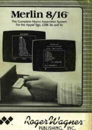
The Western Design Center, Inc.W65C816S <strong>Data</strong> <strong>Sheet</strong>VDDAO-A7A8-A15DO-D7 (816)ADDRESS BUFFER (LOW)ADDRESS BUFFER (HIGH)DATA BUS/BANK ADDRESS BUFFERINTERNAL ADDRESS BUS (16 BITS)INDEX X(16 BITS)INDEX Y(16 BITS)STACK POINTER(S) (16 BITS)ALU(16 BITS)TRANSFERSWITCHESACCUMULATOR(C) (16 BITS)(A) (8 BITS)(B) (8 BITS)PROG. COUNTER(PC) (16 BITS)DIRECT (D)(16 BITS)PROG. BANK (PBR)(8 BITS)DATA BANK (DBR)(8 BITS)DATALATCH/PREDECODEINTERNAL SPECIAL BUS (16 BITS)INTERNAL DATA BUS (16 BITS)PREDECODEREGISTER TRANSFERLOGICPROCESSORSTATUS (P)(8 BITS)INTERUPTLOGICINSTRUCTION DECODESUM OF MINTERMSINSTRUCTION REGISTER(8 BITS)TIMINGCONT.INSTRUCTION DECODEMINTERMSCLOCKGEN-ERATORSYSTEMCONT.VSSABORTBIRQBNMIBRESBRDYPHI2RWBVPAVDAMLBVPBEMXBEFigure 2-1W65C816S Internal Architecture Simplified Block DiagramThe Western Design Center W65C816S 11
The Western Design Center, Inc.W65C816S <strong>Data</strong> <strong>Sheet</strong>Table 2-1 W65C816S <strong>Microprocessor</strong> Programming Model8 BITS 8 BITS 8 BITS<strong>Data</strong> Bank Register(DBR)X Register (XH) X Register (XL)<strong>Data</strong> Bank Register(DBR)Y Register (YH) Y Register (YL)00 Stack Register (SH) Stack Register (SL)Accumulator (B) (C) Accumulator (A)Program Bank Register(PBR)Program (PCH) Counter (PCL)00 Direct Register (DH) Direct Register (DL)Shaded blocks = 6502 registers1 BBRK command:1=BRK 0=IRQN V M X D I Z CCarry 1=trueZero 1=result zeroIRQ disable 1=disableDecimal mode 1=trueIndex Register Select 1=8-bit, 0=16-bitMemory Select 1=8-bit, 0=16-bitOverflow 1=trueEmulation 1=6502 Emulation ModeNegative 1=negative0=Native ModeEThe Western Design Center W65C816S 12
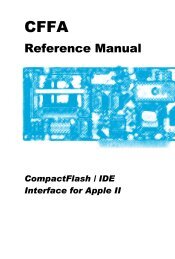
The Western Design Center, Inc.3 PIN FUNCTION DESCRIPTIONW65C816S <strong>Data</strong> <strong>Sheet</strong>MLBIRQBABORTBRDYVPBVSSRESBVDAMXPHI2BE6 5 4 3 2 1 44 43 42 41 40NMIB739NCVPA838RWBVDD937VDDA01036D0A1NC1112W65C816S3534D1D2A21333D3A31432D4A41531D5A51630D6A61729D718 19 20 21 22 23 24 25 26 27 28A7A8A9A10A11VSSVSSA12A13A14A15Figure 3-1 W65C816S 44 Pin PLCC PinoutThe Western Design Center W65C816S 13
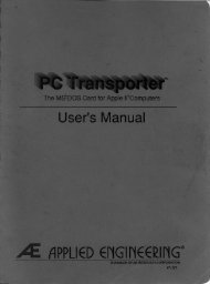
The Western Design Center, Inc.W65C816S <strong>Data</strong> <strong>Sheet</strong>VPBRDYABORTIRQBMLBNMIBVPAVDDA0A1A2A3A4A5A6A7A8A9A10A11W65C816SRESBVDAMXPHI2BEERWBD0D1D2D3D4D5D6D7A15A14A13A12VSSFigure 3-2 W65C816S 40 Pin PDIP PinoutThe Western Design Center W65C816S 14
The Western Design Center, Inc.W65C816S <strong>Data</strong> <strong>Sheet</strong>MLBIRQBABORTBRDYVPBVSSRESBVDAMXPHI2BE44 43 42 41 40 39 38 37 36 35 34NMIB133EVPA232RWBVDD331VDDA0430D0A1529D1NC6W65C816S28D2A2727D3A3826D4A4925D5A51024D6A61123D712 13 14 15 16 17 18 19 20 21 22A7A8A9A10A11VSSVSSA12A13A14A15Figure 3-3 W65C816S 44 PIN QFP PinoutThe Western Design Center W65C816S 15
The Western Design Center, Inc.W65C816S <strong>Data</strong> <strong>Sheet</strong>Table 3-1 Pin Function TablePinA0-A15ABORTBBEPHI2D0-D7EIRQBMLBMXNCNMIBRDYRESBRWBVDAVPBVPAVDDVSSDescriptionAddress BusAbort InputBus EnablePhase 2 In Clock<strong>Data</strong> Bus/Bank Address BusEmulation OR Native Mode SelectInterrupt RequestMemory LockMemory and Index Register Mode SelectNo ConnectNon-Maskable InterruptReadyResetRead/WriteValid <strong>Data</strong> AddressVector PullValid Program AddressPositive Power SupplyInternal Logic Ground3.1 Abort (ABORTB)The Abort (ABORTB) negative pulse active input is used to abort instructions (usually due to an Address Buscondition). A negative transition will inhibit modification of any internal register during the current instruction.Upon completion of this instruction, an interrupt sequence is initiated. The location of the aborted OpCode isstored as the return address in stack memory. The Abort vector address is 00FFF8,9 (Emulation mode) or00FFE8,9 (Native mode). Note that ABORTB is a pulse-sensitive signal; i.e., an abort will occur whenever thereis a negative pulse (or level) on the ABORTB pin during a PHI2 clock.3.2 Address Bus (A0-A15)The sixteen Address Bus (A0-A15) output lines along with the bank address (multiplexed on the first half cycle ofthe <strong>Data</strong> Bus (D0-D7) pins) form the 24-bit Address Bus for memory and I/O exchange on the <strong>Data</strong> Bus. Whenusing the W65C816S, the address lines may be set to the high impedance state by the Bus Enable (BE) signal.3.3 Bus Enable (BE)The Bus Enable (BE) input signal allows external control of the Address and <strong>Data</strong> Buffers, as well as the RWBsignal. With Bus Enable high, the RWB and Address Buffers are active. The <strong>Data</strong>/Address Buffers are activeduring the first half of every cycle and the second half of a write cycle. When BE is low, these buffers aredisabled. Bus Enable is an asynchronous signal.3.4 <strong>Data</strong>/Bank Address Bus (D0-D7)The Western Design Center W65C816S 16
The Western Design Center, Inc.W65C816S <strong>Data</strong> <strong>Sheet</strong>The <strong>Data</strong>/Bank Address Bus (D0-D7) pins provide both the Bank Address and <strong>Data</strong>. The bank address is presentduring the first half of a memory cycle, and the data value is read or written during the second half of the memorycycle. Two memory cycles are required to transfer 16-bit values. These lines may be set to the high impedancestate by the Bus Enable (BE) signal.3.5 Emulation Status (E)The Emulation Status (E) output reflects the state of the Emulation (E) mode flag in the Processor Status (P)Register. This signal may be thought of as an OpCode extension and used for memory and system management.3.6 Interrupt Request (IRQB)The Interrupt Request (IRQB) negative level active input signal is used to request that an interrupt sequence beinitiated. When the IRQB Disable (I) flag is cleared, a low input logic level initiates an interrupt sequence afterthe current instruction is completed. The Wait-for-Interrupt (WAI) instruction may be executed to ensure theinterrupt will be recognized immediately. The Interrupt Request vector address is 00FFFE,F (Emulation mode) or00FFEE,F (Native mode). Since IRQB is a level-sensitive input, an interrupt will occur if the interrupt source wasnot cleared since the last interrupt. Also, no interrupt will occur if the interrupt source is cleared prior to interruptrecognition. The IRQB signal going low causes 4 bytes of information to be pushed onto the stack before jumpingto the interrupt handler. The first byte is PBR followed by PCH, PCL and P (Processor Status Register). Theseregister values are used by the RTI instruction to return the processor to its original state prior to handling the IRQinterrupt (see Table 6-1)3.7 Memory Lock (MLB)The Memory Lock (MLB) active low output may be used to ensure the integrity of Read-Modify-Writeinstructions in a multiprocessor system. Memory Lock indicates the need to defer arbitration of the next bus cycle.Memory Lock is low during the last three or five cycles of ASL, DEC, INC, LSR, ROL, ROR, TRB, and TSBmemory referencing instructions, depending on the state of the M flag.3.8 Memory/Index Select Status (MX)The Memory/Index Select Status (MX) multiplexed output reflects the state of the Accumulator (M) and Index (X)elect flags (bits 5 and 4 of the Processor Status (P) Register. Flag M is valid during PHI2 negative transition andFlag X is valid during PHI2 positive transition. These bits may be thought of as OpCode extensions and may beused for memory and system management.The Western Design Center W65C816S 17
The Western Design Center, Inc.W65C816S <strong>Data</strong> <strong>Sheet</strong>3.9 Non-Maskable Interrupt (NMIB)A negative transition on the Non-Maskable Interrupt (NMIB) input initiates an interrupt sequence. A high-to-lowtransition initiates an interrupt sequence after the current instruction is completed. The Wait for Interrupt (WAI)instruction may be executed to ensure that the interrupt will be recognized immediately. The Non-MaskableInterrupt vector address is 00FFFA,B (Emulation mode) or 00FFEA,B (Native mode). Since NMIB is anedge-sensitive input, an interrupt will occur if there is a negative transition while servicing a previous interrupt.No interrupt will occur if NMIB remains low after the negative transition was processed. The NMIB signal goinglow causes 4 bytes of information to be pushed onto the stack before jumping to the interrupt handler. The firstbyte on the stack is the PBR followed by the PCH, PCL and P, these register values are used by the RTIinstruction to return the processor to its original state prior to the NMI interrupt.3.10 Phase 2 In (PHI2)Phase 2 In (PHI2) is the system clock input to the microprocessor. PHI2 can be held in either state to preserve thecontents of internal registers and reduce power as a Standby mode.3.11 Read/Write (RWB)The Read/Write (RWB) output signal is used to control whether the microprocessor is "Reading" or "Writing" tomemory. When the RWB is in the high state, the microprocessor is reading data from memory or I/O. WhenRBW is low the <strong>Data</strong> Bus contains valid data from the microprocessor which is to written to the addressedmemory location. The RWB signal is set to the high impedance state when Bus Enable (BE) is low.3.12 Ready (RDY)The Ready (RDY) is a bi-directional signal. When it is an output it indicates that a Wait for Interrupt (WAI)instruction has been executed halting operation of the microprocessor. A low input logic level will halt themicroprocessor in its current state. Returning RDY to the active high state releases the microprocessor to continueprocessing following the next PHI2 negative transition. The RDY signal is internally pulled low following theexecution of a Wait for Interrupt (WAI) instruction, and then returned to the high state when a RESB, ABORTB,NMIB, or IRQB external interrupt is active. This feature may be used to reduce interrupt latency by executing theWAI instruction and waiting for an interrupt to begin processing. If the IRQB Disable flag has been set, the nextinstruction will be executed when the IRQB occurs. The processor will not stop after a WAI instruction if RDYhas been forced to a high state. The Stop (STP) instruction has no effect on RDY. The RDY pin has an activepull-up and when outputting a low level, the pull-up is turned off to reduce power. The RDY pin can be wiredORed.The Western Design Center W65C816S 18
The Western Design Center, Inc.3.13 Reset (RESB)W65C816S <strong>Data</strong> <strong>Sheet</strong>The Reset (RESB) active low input is used to initialize the microprocessor and start program execution. The Reset inputbuffer has hysteresis such that a simple R-C timing circuit may be used with the internal pull-up device. The RESB signalmust be held low for at least two clock cycles after VDD reaches operating voltage. Ready (RDY) has no effect while RESBis being held low. The stack pointer must be initialized by the user's software. During the Reset conditioning period thefollowing processor initialization takes place:RegistersD=0000 SH=01, SL=*DBR=00 XH=00, XL=*PBR=00 YH=00, YL=*A=*SignalsE=1 VDA=0MX=1 VPB=1RWB=1 VPA=0P RegisterN V M X D I Z C/E* * 1 1 0 1 * */1 *=not initializedWhen Reset is brought high, an interrupt sequence is initiated• STP and WAI instructions are cleared• RWB remains in the high state during the stack address cycles.• The Reset vector address is 00FFFC,D.(see Table 6-1 for Vectors)• PC is loaded with the contents of 00FFFC,D3.14 Valid <strong>Data</strong> Address (VDA) and Valid Program Address (VPA)The Valid <strong>Data</strong> Address (VDA) and Valid Program Address (VDA) output signals indicate valid memoryaddresses when high and are used for memory or I/O address qualification.VDA VPA0 0 Internal Operation Address and <strong>Data</strong> Bus available. The Address Bus may be invalid.0 1 Valid program address-may be used for program cache control.1 0 Valid data address-may be used for data cache control.1 1 OpCode fetch-may be used for program cache control and single step control3.15 VDD and VSSVDD is the positive supply voltage and VSS is system logic ground.3.16 Vector Pull (VPB)The Vector Pull (VPB) active low output indicates that a vector location is being addressed during an interruptsequence. VPB is low during the last two interrupt sequence cycles, during which time the processor loads the PCwith the interrupt handler vector location. The VPB signal may be used to select and prioritize interrupts fromseveral sources by modifying the vector addresses.The Western Design Center W65C816S 19
The Western Design Center, Inc.4 ADDRESSING MODESW65C816S <strong>Data</strong> <strong>Sheet</strong>The W65C816S is capable of directly addressing 16 MBytes of memory. This address space has specialsignificance within certain addressing modes, as follows:4.1 Reset and Interrupt VectorsThe Reset and Interrupt Vectors use the majority of the fixed addresses between 00FFE0 and 00FFFF.4.2 StackThe Stack may be use memory from 000000 to 00FFFF. The effective address of Stack and Stack Relativeaddressing modes will be always be within this range.4.3 DirectThe Direct addressing modes are usually used to store memory registers and pointers. The effective addressgenerated by Direct, Direct,X and Direct,Y addressing modes is always in Bank 0 (000000-00FFFF).4.4 Program Address SpaceThe Program Bank register is not affected by the Relative, Relative Long, Absolute, Absolute Indirect, andAbsolute Indexed Indirect addressing modes or by incrementing the Program Counter from FFFF. The onlyinstructions that affect the Program Bank register are: RTI, RTL, JML, JSL, and JMP Absolute Long. Programcode may exceed 64K bytes although code segments may not span bank boundaries.4.5 <strong>Data</strong> Address SpaceThe <strong>Data</strong> Address space is contiguous throughout the 16 MByte address space. Words, arrays, records, or anydata structures may span 64 KByte bank boundaries with no compromise in code efficiency. The followingaddressing modes generate 24-bit effective addresses:• Absolute a• Absolute a,x• Absolute a,y• Absolute Long al• Absolute Long Indexed al,x• Direct Indexed Indirect (d,x)• Direct Indirect (d)• Direct Indirect Indexed (d),y• Direct Indirect Long [d]• Direct Indirect Long Indexed [d],y• Stack Relative Indirect Indexed (d,x),yThe following addressing mode descriptions provide additional detail as to how effective addresses arecalculated. Twenty-four addressing modes are available for the W65C816S.The Western Design Center W65C816S 20
The Western Design Center, Inc.W65C816S <strong>Data</strong> <strong>Sheet</strong>Absolute -aWith Absolute (a) addressing the second and third bytes of the instruction form the low-order 16 bits of theeffective address. The <strong>Data</strong> Bank Register contains the high-order 8 bits of the operand address.Instruction: OpCode addrl addrhOperand DBR addrh addrlAbsolute Indexed Indirect-(a,x)With Absolute Indexed Indirect ((a,x)) addressing the second and third bytes of the instruction are added to the XIndex Register to form a 16-bit pointer in Bank 0. The contents of this pointer are loaded in the Program Counterfor the JMP instruction. The Program Bank Register is not changed.then:PC = (address)Instruction: OpCode addrl addrhAbs olute Indexed with X-a,xPBRaddrhaddressWith Absolute Indexed with X (a,x) addressing the second and third bytes of the instruction are added to the XIndex Register to form the low-order 16-bits of the effective address. The <strong>Data</strong> Bank Register contains thehigh-order 8 bits of the effective address.addrlX RegInstruction: OpCode addrl addrhOperand Address:DBR addrh addrl+ X Regeffective addressAbsolute Indexed with Y-a,yWith Absolute Indexed with Y (a,y) addressing the second and third bytes of the instruction are added to the YIndex Register to form the low-order 16-bits of the effective address. The <strong>Data</strong> Bank Register contains thehigh-order 8 bits of the effective address.Instruction: OpCode addrl addrhOperand Address:DBR addrh addrl+ Y Regeffective addressThe Western Design Center W65C816S 21
The Western Design Center, Inc.W65C816S <strong>Data</strong> <strong>Sheet</strong>Absolute Indirect-(a)With Absolute Indirect ((a)) addressing the second and third bytes of the instruction form an address to a pointer inBank 0. The Program Counter is loaded with the first and second bytes at this pointer. With the Jump Long(JML) instruction, the Program Bank Register is loaded with the third byte of the pointer.Instruction: OpCode addrl addrhIndirect 00 addrh addrlAbsolute Long Indexed With X-al,xWith Absolute Long Indexed with X (al,x) addressing the second, third and fourth bytes of the instruction form a24-bit base address. The effective address is the sum of this 24-bit address and the X Index Register.Absolute Long-alInstruction: OpCode addrl addrh baddrOperand Address:baddr addrh addrl+ X Regeffective addressWith Absolute Long (al) addressing the second, third and fourth byte of the instruction form the 24-bit effectiveaddress.Accumulator-AInstruction: OpCode addrl addrh baddrOperand Address: baddr addrh addrlWith Accumulator (A) addressing the operand is the Accumulator.Block Move-xycBlock Move (xyc) addressing is used by the Block Move instructions. The second byte of the instruction containsthe high-order 8 bits of the destination address and the Y Index Register contains the low-order 16 bits of thedestination address. The third byte of the instruction contains the high-order 8 bits of the source address and the XIndex Register contains the low-order bits of the source address. The C Accumulator contains one less than thenumber of bytes to move. The second byte of the block move instructions is also loaded into the <strong>Data</strong> BankRegister.Instruction: OpCode dstbnk srcbnkdstbnk Y DBRSource Address: srcbnk X RegDest. Address; DBR Y RegIncrement X and Y (MVN) or decrement X and Y (MVP) and decrement C (if greater than zero), then PC=PC+3.The Western Design Center W65C816S 22
The Western Design Center, Inc.W65C816S <strong>Data</strong> <strong>Sheet</strong>Direct Indexed Indirect-(d,x)Direct Indexed Indirect ((d,x)) addressing is often referred to as Indirect X addressing. The second byte of theinstruction is added to the sum of the Direct Register and the X Index Register. The result points to the Xlow-order 16 bits of the effective address. The <strong>Data</strong> Bank Register contains the high-order 8 bits of the effectiveaddress.Instruction: OpCode offsetthen: + DBRDirect Register+ offsetdirect address+ X Reg00 (address)Operand Address:effective addressDirect Indexed with X-d,xWith Direct Indexed with X (d,x) addressing the second byte of the instruction is added to the sum of the DirectRegister and the X Index Register to form the 16-bit effective address. The operand is always in Bank 0.Instruction: OpCode offsetDirect Register+ offsetdirect address+ X RegOperand Address: 00 effective addressDirect Indexed with Y-d,yWith Direct Indexed with Y (d,y) addressing the second byte of the instruction is added to the sum of the DirectRegister and the Y Index Register to form the 16-bit effective address. The operand is always in Bank 0.Instruction: OpCode offsetDirect Register+ offsetdirect address+ Y RegOperand Address: 00 effective addressThe Western Design Center W65C816S 23
The Western Design Center, Inc.W65C816S <strong>Data</strong> <strong>Sheet</strong>Direct Indirect Indexed-(d),yDirect Indirect Indexed ((d),y) addressing is often referred to as Indirect Y addressing. The second byte of theinstruction is added to the Direct Register (D). The 16-bit content of this memory location is then combined withthe <strong>Data</strong> Bank register to form a 24-bit base address. The Y Index Register is added to the base address to formthe effective address.Instruction: OpCode offsetthen: + DBROperand Address:Direct Register+ offset00 (direct address)base address+ Y Regeffective addressDirect Indirect Long Indexed-[d],yWith Direct Indirect Long Indexed ([d],y) addressing the 24-bit base address is pointed to by the sum of thesecond byte of the instruction and the Direct Register. The effective address is this 24-bit base address plus the YIndex Register.Instruction: OpCode offsetDirect Register+ offset00 direct addressbase addressthen + Y RegOperand Address:effective addressDirect Indirect Long-[d]With Direct Indirect Long ([d]) addressing the second byte of the instruction is added to the Direct Register toform a pointer to the 24-bit effective address.Instruction: OpCode offsetDirect Registerthen: + offsetOperand Address:00 (direct address)direct addressThe Western Design Center W65C816S 24
The Western Design Center, Inc.W65C816S <strong>Data</strong> <strong>Sheet</strong>Direct Indirect-(d)With Direct Indirect ((d)) addressing the second byte of the instruction is added to the Direct Register to form apointer to the low-order 16 bits of the effective address. The <strong>Data</strong> Bank Register contains the high-order 8 bits ofthe effective address.Instruction: OpCode offsetthen: + DBROperand Address:Direct Register+ offset00 (direct address)effective addressDirect-dWith Direct (d) addressing the second byte of the instruction is added to the Direct Register (D) to form theeffective address. An additional cycle is required when the Direct Register is not page aligned (DL not equal 0).The Bank register is always 0.Instruction: OpCode offsetDirect Register+ offsetOperand Address: 00 effective addressImmediate-#With Immediate (#) addressing the operand is the second byte (second and third bytes when in the16-bit mode) of the instruction.Implied-iImplied (i) addressing uses a single byte instruction. The operand is implicitly defined by the instruction.Program Counter Relative Long-rlThe Program Counter Relative Long (rl) addressing mode is used with only with the unconditional Branch Longinstruction (BRL) and the Push Effective Relative instruction (PER). The second and third bytes of theinstruction are added to the Program Counter, which has been updated to point to the OpCode of the nextinstruction. With the branch instruction, the Program Counter is loaded with the result. With the Push EffectiveRelative instruction, the result is stored on the stack. The offset is a signed 16-bit quantity in the range from-32768 to 32767. The Program Bank Register is not affected.The Western Design Center W65C816S 25
The Western Design Center, Inc.W65C816S <strong>Data</strong> <strong>Sheet</strong>Program Counter Relative -rThe Program Counter Relative (r) addressing is referred to as Relative Addressing and is used only with theBranch instructions. If the condition being tested is met, the second byte of the instruction is added to the ProgramCounter, which has been updated to point to the OpCode of the next instruction. The offset is a signed 8-bitquantity in the range from -128 to 127. The Program Bank Register is not affected.Stack-sStack (s) addressing refers to all instructions that push or pull data from the stack, such as Push, Pull, Jump toSubroutine, Return from Subroutine, Interrupts, and Return from Interrupt. The bank address is always 0.Interrupt Vectors are always fetched from Bank 0.Stack Relative -d,sWith Stack Relative (d,s) addressing the low-order 16 bits of the effective address is formed from the sum of thesecond byte of the instruction and the stack pointer. The high-order 8 bits of the effective address are always zero.The relative offset is an unsigned 8-bit quantity in the range of 0 to 255.Instruction: OpCode offsetStack Pointerthen: + offsetOperand Address: 00 effective addressStack Relative Indirect Indexed-(d,s),yWith Stack Relative Indirect Indexed ((d,s),y) addressing the second byte of the instruction is added to the StackPointer to form a pointer to the low-order 16-bit base address in Bank 0. The <strong>Data</strong> Bank Register contains thehigh-order 8 bits of the base address. The effective address is the sum of the 24-bit base address and the Y IndexRegister.Instruction: OpCode offsetStack Pointeroffset00 S + offsetthen + DBRbase address+ Y RegOperand Address:effective addressThe Western Design Center W65C816S 26
The Western Design Center, Inc.W65C816S <strong>Data</strong> <strong>Sheet</strong>Table 4-1 Addressing Mode SummaryAddress Mode Instruction Times in Memory Cycle Memory Utilization in Number ofProgram Sequence BytesOriginal 8-bitNMOS6502New W65C816S Original 8-bitNMOS6502NewW65C816SAbsolute 4 (5) 4 (3,5) 3 3Absolute Indexed Indirect (Jump) - 6 - 3Absolute Indirect (Jump) 5 5 3 3Absolute Long - 5 (3) - 4Absolute Long, X - 5 (3) - 4Absolute, X 4 (1,5) 4 (1,3,5) 3 3Absolute, Y 4 (1) 4 (1,3) 3 3Accumulator 2 2 1 1Block Move (xyc) - 7 - 3Direct 3 (5) 3 (3,4,5) 2 2Direct Indexed Indirect (d,x) 6 6 (3,4) 2 2Direct Indirect - 5 (3,4) - 2Direct Indirect Indexed (d),y 5 (1) 5 (1,3,4) 2 2Direct Indirect Indexed Long [d],y - 6 (3,4) - 2Direct Indirect Long - 6 (3,4) - 2Direct, X 4 (5) 4 (3,4,5) 2 2Direct, Y 4 4 (3,4) 2 2Immediate 2 2 (3) 2 2 (3)Implied 2 2 1 1Relative 2 (1,2) 2 (2) 2 2Relative Long - 3 (2) - 3Stack 3-7 3-8 1-3 1-4Stack Relative - 4 (3) - 2Stack Relative Indirect Indexed - 7 (3) - 2Notes (these are indicated in parentheses):1. Page boundary, add 1 cycle if page boundary is crossed when forming address.2. Branch taken, add 1 cycle if branch is taken.3. M = 0 or X = 0, 16 bit operation, add 1 cycle, add 1 byte for immediate.4. Direct register low (DL) not equal zero, add 1 cycle.5. Read-Modify-Write, add 2 cycles for M = 1, add 3 cycles for M = 0.The Western Design Center W65C816S 27
The Western Design Center, Inc.5 TIMING, AC AND DC CHARACTERISTICSW65C816S <strong>Data</strong> <strong>Sheet</strong>5.1 Absolute Maximum RatingsTable 5-1 Absolute Maximum RatingsRating Symbol ValueSupply Voltage VDD -0.3 to +7.0VInput Voltage VIN -0.3 to VDD +0.3VStorage Temperature TS -55°C to +150°CThis device contains input protection against damage due to high static voltages or electric fields; however,precautions should be taken to avoid application of voltages higher than the maximum rating.Note: Exceeding these ratings may result in permanent damage. Functional operation under the conditions isnot implied.The Western Design Center W65C816S 28
The Western Design Center, Inc.5.2 DC Characteristics TA = -40°C to +85°CW65C816S <strong>Data</strong> <strong>Sheet</strong>Table 5-2 DC CharacteristicsSymbol5.0 +/ - 5% 3.3 +/ - 10% 3.0 +/ - 5% 2.5 +/ - 5% 1.8 +/ - 5% UnitsMin Max Min Max Min Max Min Max Min MaxVDO 4.25 5.25 3.0 3.6 2.85 3.15 2.375 2.625 1.71 1.89 VInput High VoltageVihABORTB, BE, <strong>Data</strong>, IRQB, RDY, VDDx0.8 VDD+0.3 VDDx0.8 VDD+0.3 VDDx0.8 VDD+0.3 VDDx0.8 VDD+0.3 VDDx0.8VDD+0.3NMIB, PHI2, RESBVVilInput Low VoltageABORTB, BE, <strong>Data</strong>, IRQB, RDY, VSS-0.3 VDDx0.2 VSS-0.3 VDDx0.2 VSS-0.3 VDDx0.2 VSS-0.3 VDDx0.2 VSS-0.3 VDDx0.2 VNMIB, PHI2, RESBIpupRDY Input Pullup-Current(VIN=VDDx0.8)5 20 5 20 5 20 2 10 2 10 µAIin Input Leakage Current (Vin=0.4 to 2.4)PHI2, Address, <strong>Data</strong>, RWB, (Off state, -0.2 0.2 -0.2 0.2 -0.2 0.2 -0.2 0.2 -0.2 0.2 µABE=0), All other inputsOutput High Voltage (Vol=VDD-0.4V)Ioh Address, <strong>Data</strong>, E, MLB, MX,700 - 300 - 300 - 200 - 100 - µARWB, VDA, VPA, VPBIolOutput Low Voltage (Vol=VSS+0.4V)Address, <strong>Data</strong>, E, MLB, MX, RWB, 1.6 - 1.6 - 1.6 - 1.0 - .5 - mAVDA, VPA, VPBIddSupply Current (no load)- 2.01.51.51.00.75 mA/----Supply Current (core)- 1.00.60.50.40.30 MHzStandby Current (No Load, <strong>Data</strong> Bus =VSS or VDD)IsbyABORTB, BE, IRQB, NMIB, RESB,- 1 - 1 - 1 - 1µAPHI2=VDDCapacitance (Vin=0V, TA=25°C, f=1MHz)ABORTB, BE, IRQB, NMIB, PHI2,Cin RBW, RESB, RDY,pF- 5 - 5 - 5 - 5 - 5Cts Address, <strong>Data</strong>, R/W- (Off state)pF* Not inspected during production test;verified on a sample basis.IDD (mA)1.21.12.01.81.61.41.21.00.80.60.40.20.001 MHz Operation@85°CTypical 0.6u processed device· (With tester loading)• (CORE power only)·•·•1 2 3 4 5 6·•VDD (VOLTS)Table 5-3 IDD vs. VDD·•VDD (VOLTS)6.05.55.04.54.0Typical 0.6u processed device @85°C3.53.0··2.52.0 ·1.51.00.00 2 4 6 8 10 12 14 16 18 20F Max (MHz)Table 5- 4 F Max vs. VDD·The Western Design Center W65C816S 29
The Western Design Center, Inc.Table 5-2 W65C816S AC CharacteristicsW65C816S <strong>Data</strong> <strong>Sheet</strong>Symbol Parameter 5.0 +/- 5% 3.3 +/- 10% 3.0 +/- 5% 2.5 +/- 5% 1.8 +/- 5% Units14MHz 8MHz 8MHz 4MHz 2MHzMin Max Min Max Min Max Min Max Min MaxVDD 4.75 5.25 3.0 3.6 2.85 3.15 2.375 2.675 1.71 1.89 VtCYC Cycle Time 70 DC 125 DC 125 DC 250 DC 500 DC nStPWL Clock Pulse Width Low 35 - 63 - 63 - 125 - 250 - nStPWH Clock Pulse Width High 35 - 62 - 62 - 125 - 250 - nStF,tR Fall Time, Rise Time - 5 - 5 - 5 - 5 - 5 nStAH A0-A15 Hold Time 10 - 10 - 10 - 20 - 40 - nStADS A0-A15 Setup Time - 30 - 40 - 40 - 75 - 150 nStBH BA0-BA7 Hold Time 10 - 10 - 10 - 20 - 40 - nStBAS BA0-BA7 Setup Time - 33 - 40 - 40 - 75 - 150 nStACC Access Time 30 - 70 - 70 - 130 - 365 - nStDHR Read <strong>Data</strong> Hold Time 10 - 10 - 10 - 20 - 40 - nStMDS Write <strong>Data</strong> Delay Time - 30 - 40 - 40 - 70 - 140 nStDHW Write <strong>Data</strong> Hold Time 10 - 10 - 10 - 20 - 40 - nStPCS Processor Control Setup Time 10 - 15 - 15 - 30 - 60 - nStPCH Processor Control Hold Time 10 - 10 - 10 - 20 - 40 - nStEH E, MX Output Hold Time - 5 - 5 - 5 - 5 - 5 nStES E, MX Output Setup Time 10 - 15 - 15 - 30 - 60 - nSCEXT Capacitive Load (1) - 35 - 35 - 35 - 35 - 35 PftBVD be TO Valid <strong>Data</strong> (2) - 25 - 30 - 30 - 60 - 120 nS1. Test or loading on all outputs.2. BE to High Impedance State is not testable but should be the same amount of time as BE to Valid <strong>Data</strong>.The Western Design Center W65C816S 30
The Western Design Center, Inc.W65C816S <strong>Data</strong> <strong>Sheet</strong>tFtRPHI2tPWLtPWHRWB, SYNCVPB, MLB A0-A15Read <strong>Data</strong>tDHRWrite <strong>Data</strong>tDHWtAHtADStACCtMDSWrite <strong>Data</strong>tDSRtAHsee note 1tDHRtDHWIRQB, NMIB, RESB,RDYtPCStPCHABORTBtPCSM/XMIEHtESXXtEHMMtEStEHEtEHBE<strong>Data</strong>tBVD1. Timing measurement points are 50% VDD.Figure 5-1 General Timing DiagramThe Western Design Center W65C816S 31
The Western Design Center, Inc.6 OPERATION TABLESTable 6-1 W65C816S Instruction Set-Alphabetical Sequence(continued on following page)W65C816S <strong>Data</strong> <strong>Sheet</strong>1. ADC Add Memory to Accumulator with Carry 30. INY Increment Index Y by One2. AND "AND" Memory with Accumulator 31. JML Jump Long3. ASL Shift One Bit Left, Memory or Accumulator 32. JMP Jump to New Location4. BCC Branch on Carry Clear (C=0) 33. JSL Jump Subroutine Long5. BCS Branch on Carry Set (C=1) 34. JSR Jump to News Location Saving Return6. BEQ Branch if Equal (Z=1) 35. LDA Load Accumulator with Memory7. BIT Bit Test 36. LDX Load Index X with Memory8. BMI Branch if Result Minus (N=1) 37. LDY Load Index Y with Memory9. BNE Branch if Not Equal (Z=0) 38. LSR Shift One Bit Right (Memory or Accumulator)10. BPL Branch if Result Plus (N=0) 39. MVN Block Move Negative11. BRA Branch Always 40. MVP Block Move Positive12. BRK Force Break 41. NOP No Operation13. BRL Branch Always Long 42. ORA "OR" Memory with Accumulator14.43. Push Effective Absolute Address on Stack (orBVC Branch on Overflow Clear (V=0)PEAPush Immediate <strong>Data</strong> on Stack)15.44. Push Effective Absolute Address on Stack ( OrBVS Branch on Overflow Set (V=1)PEIPush Direct <strong>Data</strong> on Stack)16.45. Push Effective Program Counter RelativeCLC Clear Carry FlagPERAddress on Stack17. CLD Clear Decimal Mode 46. PHA Push Accumulator on Stack18. CLI Clear Interrupt Disable Bit 47. PHB Push <strong>Data</strong> Bank Register on Stack19. CLV Clear Overflow Flag 48. PHD Push Direct Register on Stack20. CMP Compare Memory and Accumulator 49. PHK Push Program Bank Register on Stack21. COP Coprocessor 50. PHP Push Processor Status on Stack22. CPX Compare Memory and Index X 51. PHX Push Index X on Stack23. CPY Compare Memory and Index Y 52. PHY Push Index Y on Stack24. DEC Decrement Memory or Accumulator by One 53. PLA Pull Accumulator from Stack25. DEX Decrement Index X by One 54. PLB Pull <strong>Data</strong> Bank Register from Stack26. DEY Decrement Index Y by One 55. PLD Pull Direct Register from Stack27. EOR "Exclusive OR" Memory with Accumulator 56. PLP Pull Processor Status from Stack28. INC Increment Memory or Accumulator by One 57. PLX Pull Index X from Stack29. INX Increment Index X by One 58. PLY Pull Index Y from StackThe Western Design Center W65C816S 32
The Western Design Center, Inc.W65C816S <strong>Data</strong> <strong>Sheet</strong>59. 5 REP Reset Status Bits 76. TAY Transfer Accumulator to Index Y60. ROL Rotate One Bit Left (Memory or 77. TCD Transfer C Accumulator to Direct RegisterAccumulator)61. ROR Rotate One Bit Right (Memory or 78. TCS Transfer C Accumulator to Stack Pointer RegisterAccumulator)62. RTI Return from Interrupt 79. TDC Transfer Direct Register to C Accumulator63. RTL Return from Subroutine Long 80. TRB Test and Reset Bit64. RTS Return from Subroutine 81. TSB Test and Set Bit65. SBC Subtract Memory from Accumulator 82. TSC Transfer Stack Pointer Register to C Accumulatorwith Borrow66. SEP Set Processor Status Bit 83. TSX Transfer Stack Pointer Register to Index X67. SEC Set Carry Flag 84. TXA Transfer Index X to Accumulator68. SED Set Decimal Mode 85. TXS Transfer Index X to Stack Pointer Register69. SEI Set Interrupt Disable Status 86. TXY Transfer Index X to Index Y70. STA Store Accumulator in Memory 87. TYA Transfer Index Y to Accumulator71. STP Stop the Clock 88. TYX Transfer Index Y to Index X72. STX Store Index X in Memory 89. WAI Wait for Interrupt73. STY Store Index Y in Memory 90. WDM Reserved for future use74. STZ Store Zero in Memory 91. XBA Exchange B and A Accumulator75. TAX Transfer Accumulator in Index X 92. XCE Exchange Carry and Emulation BitsThe Western Design Center W65C816S 33
The Western Design Center, Inc.W65C816S <strong>Data</strong> <strong>Sheet</strong>Table 6-2 Emulation Mode Vector Locations (8-bit Mode)Address Label Function00FFFE,F IRQB/BRK Hardware/Software00FFFC,D RESETB Hardware00FFFA,B NMIB Hardware00FFF8,9 ABORTB Hardware00FFF6,7 (Reserved) Hardware00FFF4,5 COP Software00FFF2,3 (Reserved)00FFF0,1 (Reserved)Table 6-3 Native Mode Vector Locations (16-bit Mode)Address Label Function00FFFE,F IRQB Hardware00FFFC,D (Reserved)00FFFA,B NMIB Hardware00FFF8,9 ABORTB00FFF6,7 BRK Software00FFF4,5 COP Software00FFF2,3 (Reserved)00FFF0,1 (Reserved)The VP output is low during the two cycles used for vector location access. When an interrupt is executed,D=0 and I=1 in Status Register P.The Western Design Center W65C816S 34
The Western Design Center, Inc.Table 6-4 OpCode MatrixW65C816S <strong>Data</strong> <strong>Sheet</strong>MSD0123456789ABCDEFLSD0 1 2 3 4 5 6 7 8 9 A B C D E FBRK s7,2BPL r2,2JSR a6,3BMI r2,2RTI s7,1BVC r2,2RTS s6,1BVS r2,2BRA r2,2 !BCC r2,2LDY #2,2BCS r2,2CPY #2,2BNE r2,2CPX #2,2BEQ r2,2ORA(d,x)6,2ORA(d),y5,2AND(d,x)6,2AND(d),y5,2EOR(d,x)6,2EOR (d),y5,2ADC(d,x)6,2ADC(d),y5,2STA(d,x)6,2STA(d),y6,2LDA (d,x)6,2LDA (d),y5,2CMP (d,x)6,2CMP (d),y5,2SBC (d,x)6,2SBC (d),y5,2COP s7,2 *ORA(d)5,2 !JSL al8,4 *AND(d)5,2 !WDM2,2 *EOR (d)5,2 !PER s6,3 *ADC(d)5,2 !BRL rl3,3 *STA (d)5,2 !LDX #2,2LDA (d)5,2 !REP #3,2 *CMP (d)5,2 !SEP #3,2 *SBC (d)5,2 !ORA d,s4,2 *ORA(d,s),y7,2 *AND d,s4,2 *AND(d,s),y7,2 *EOR d,s4,2 *EOR(d,s),y7,2 *ADC d,s4,2 *ADC(d,s),y7,2 *STA d,s4,2 *STA(d,s),y7,2 *LDA d,s4,2 *LDA(d,s),y7,2 *CMP d,s4,2 *CMP(d,s),y7,2 *SBC d,s4,2 *SBC(d,s),y7,2 *TBS d5,2 !TRB d5,2 !BIT d3,2BIT d,x4,2 !MVP xyc7,3 *MVN xyc7,3 *STZ d3,2 !STZ d,x4,2 !STY d3,2STY d,x4,2LDY d3,2LDY d,x4,2CPY d3,2PEI s6,2 *CPX d3,2PEA s5,3 *ORA d3,2ORA d,x4,2AND d3,2AND d,x4,2EOR d3,2EOR d,x4,2ADC d3,2ADC d,x4,2STA d3,2STA d,x4,2LDA d3,2LDA d,x4,2CMP d3,2CMP d,x4,2SBC d3,2SBC d,x4,2ASL d5,2 *ASL d,x6,2 *ROL d5,2 *ROL d,x6,2 *LSR d5,2 *LSR d,x6,2 *ROR d5,2 *ROR d,x6,2 *STX d3,2 *STX d,y4,2 *LDX d3,2 *LDX d,y4,2 *DEC d5,2 *DEC d,x6,2 *INC d5,2 *INC d,x6,2 *ORA [d]6,2ORA[d],y6,2AND [d]6,2AND[d],y6,2EOR [d]6,2EOR[d].y6,2ADC[d]6,2ADC[d],y6,2STA[d]6,2STA[d],y6,2LDA [d]6,2LDA[d],y6,2CMP [d]6,2CMP[d],y6,2SBC [d]6,2SBC[d],y6,2PHP s3,1CLC i2,1PLP s4,1SEC i2,1PHA s3,1CLI i2,1PLA s4,1SEI i2,1DEY i2,1TYA i2,1TAY i2,1CLV i2,1INY i2,1CLD i2,1INX i2,1SED i2,1ORA#2,2ORA a,y4,3AND#2,2AND a,y4,3EOR #2,2EOR a,y4,3ADC#2,2ADC a,y4,3BIT #2,2 !STA a,y5,3LDA#2,2LDA a,y4,3CMP #2,2CMP a,y4,3SBC #2,2SBC a,y4,3ASL A2,1INC A2,1 !ROL A2,1DEC A2,1 !LSR A2,1PHY s3,1 !ROR A2,1PLY s4,1TXA i2,1TXS i2,1TAX i2,1TSX i2,1DEX i2,1PHX s3,1 !NOP i2,1PLX s4,1 !PHD s4,1 *TCS i2,1 *PLD s5,1 *TSC i2,1 *PHK s3,1 *TCD i2,1 *RTL s6,1 *TDC i2,1 *PHB s3,1 *TXY i2,1 *PLB s4,1 *TYX i2,1 *WAI i3,1 !STP i3,1 !XBA i3,1 *XCE i2,1 *TSB a6,3 !TRB a6,3 !BIT a4,3BIT a,x4,3 !JMP a3,3JMP al4,4 *JMP (a)5,3JMP(a,x)6,3 !STY a4,3STZ a3,4 !LDY a4,3LDY a,x4,3CPY a4,3JML (a)6,3 *CPX a4,3JSR (a,x)6,3 *ORA a4,3ORA a,x4,3AND a4,3AND a,x4,3EOR a4,3EOR a,x4,3ADC a4,3ADC a,x4,3STA a4,3STA a,x5,3LDA a4,3LDA a,x4,3CMP a4,3CMP a,x4,3SBC a4,3SBC a,x4,3ASL a6,3ASL a,x7,3ROL a6,3ROL a,x7,3LSR a6,3LSR a,x7,3ROR a6,3ROR a,x7,3STX a4,3STZ a,x5,3 !LDX a4,3LDX a,y4,3DEC a6,3DEC a,x7,3INC a6,3INC a,x7,30 1 2 3 4 5 6 7 8 9 A B C D E F* = Old instruction with new addressing modes! = New InstructionORA al5,4 *ORA al,x5,4 *AND al5,4 *AND al,x5,4 *EOR al5,4 *EOR al,x5,4 *ADC al5,4 *ADC al,x5,4 *STA al5,4 *STA al,x5,4 *LDA al5,4 *LDA al,x5,4 *CMP al5,4 *CMP al,x5,4 *SBC al5,4 *SBC al,x5,4 *MSD0123456789ABCDEFThe Western Design Center W65C816S 35
The Western Design Center, Inc.Table 6-5 Operation, Operation Codes, and Status Register (continued on following 4 pages)W65C816S <strong>Data</strong> <strong>Sheet</strong>OperationMnemonic+ Add- Subtract^ ANDProcessor Status Codev ORaAa,xa,yalal,x(a)(a,x)dd,sid,xd,y(d)[d](d,s),y(d,x)(d),y[d],yrrlsxyc#7 6 5 4 3 2 1 0v Exclusive OR 1 2 3 4 5 6 7 8 9 10 11 12 13 14 15 16 17 18 19 20 21 22 23 24 N V 1 B D 1 Z CADC A+M+C→A 6D 7D 79 6F 7F 17 65 63 75 72 67 73 61 71 77 69 N V . . . . Z CAND A^M→A 2D 3E 39 2F 3F 25 23 36 32 27 33 91 31 37 29 N . . . . . Z .ASL C←15/7 6 5 4 3 2 10 ←0 0E 0A 1E 06 16 N . . . . . Z CBCC Branch if C = 0 90 . . . . . . . .BCS Branch if C = 1 B0 . . . . . . . .BEQ Branch if Z = 1 F0 . . . . . . . .BIT A ^ M (Note 1) 2C 3C 24 34 89 M 7 M 6 . . . . Z .BMI Branch if N = 0 30 . . . . . . . .BNE Branch if Z = 0 D0 . . . . . . . .BPL Branch if N = 0 10 . . . . . . . .BRA Branch Always 80 . . . . . . . .BRK Break (Note 2) 00 . . . • 0 1 . .BRL* Branch Long Always 82 . . . . . . . .BVC Branch if V = 0 50 . . . . . . . .BVS Branch if V = 1 70 . . . . . . . .CLC C → 0 18 . . . . . . . 0CLD 0 → DD8 . . . . 0 . . .CLI 0 → 1 58 . . . . . 0 . .CLV 0 → V B8 . 0 . . . . . .CMP A-M CD DD D9 CF DF C5 C3 D5 D2 C7 D3 C1 D1 D7 C9 N . . . . . Z CCOP* Co-Processor 02 . . . . 0 1 . .The Western Design Center W65C816S 36
iThe Western Design Center, Inc.W65C816S <strong>Data</strong> <strong>Sheet</strong>MnemonicOperation+ Add- Subtract^ ANDv ORv Exclusive ORTable 6-5 (continued)aAa,xa,yalal,x(a)(a,x)dd,sd,xd,y(d)[d](d,s),y(d,x)(d),y[d],yrrlsxyc#Processor Status Code7 6 5 4 3 2 1 01 2 3 4 5 6 7 8 9 10 11 12 13 14 15 16 17 18 19 20 21 22 23 24 N V 1 B D I Z CCPX X-M EC E4 E0 N . . . . . Z CCPY Y-M CC C4 C0 N . . . . . Z CDEC Decrement CE 3A DE C6 D6 N . . . . . Z .DEX X-1 → A CA N . . . . . Z .DEY Y-1 → Y 88 N . . . . . Z .EOR A v M → A4D 5D 59 4F 5F 5D 45 43 55 52 47 53 41 51 57 49 N . . . . . Z .INC Increments EE 1A FE E6 F6 N . . . . . Z .INX X+1 → X E8 N . . . . . Z .INY Y+1 → Y C8 N . . . . . Z .JML*Jump Long to newlocationDC . . . . . . . .JMP Jump to new location 4C 5C 6C 7C . . . . . . . .JSL Jump long to Subroutine 22 . . . . . . . .JSR Jump to Subroutine 20 FC . . . . . . . .LDA M → A AD BD B9 AF BF A5 A3 B5 B2 A7 B3 A1 B1 B7 A9 N . . . . . Z .LDX M → X AE BE A6 B6 A2 N . . . . . Z .LDY M → Y AC BC A4 B4 A0 N . . . . . Z .LSR 0 → 15/7 6 5 4 3 2 1 0 → C 4E 4A 5E 46 56 0 . . . . . Z CMVN* M→M NEGATIVE 54 . . . . . . . .MVP* M→M POSITIVE 44 . . . . . . . .NOP No Operation EA . . . . . . . .ORA A V M → A 0D 1D 19 0F 1F 05 03 15 12 07 13 01 11 17 09 N . . . . . Z .The Western Design Center W65C816S 37
The Western Design Center, Inc.W65C816S <strong>Data</strong> <strong>Sheet</strong>Table 6-5 (continued)Operation+ Add- Subtract^ ANDProcessor Status Codev ORaAa,xa,yalal,x(a)(a,x)dd,sd,xd,y(d)[d](d,s),y(d,x)iMnemonic(d),y[d],yrrlsxyc#7 6 5 4 3 2 1 0PEA*PEI*PER*v Exclusive OR 1 2 3 4 5 6 7 8 9 10 11 12 13 14 15 16 17 18 19 20 21 22 23 24 N V 1 B D I Z CMpc+1, Mpc+2 ? Ms-1, MsS-2 ? SM(d), M(d+1) ? Ms-1, MsS-2 ? SF4 . . . . . . . .D4 . . . . . . . .Mpc+rl, Mpc+rl+1 ? Ms-1, MsS-2 ? S 62 . . . . . . . .PHA A → Ms, S-1 → S 48 . . . . . . . .PHB DBR ? Ms, S-1 ? S 8B . . . . . . . .PHD* D ? Ms, Ms-1, S-2 ? S 0B . . . . . . . .PHK* PBR ? Ms, S-1 ? S 4B . . . . . . . .PHP P → Ms, S-1 → S 08 . . . . . . . .PHX X → Ms, S-1 → S DA . . . . . . . .PHY Y → Ms, S-1 → S 5A . . . . . . . .PLA S + 1 → S, Ms → A 68 N . . . . . Z .PLB* S + 1 → S, Ms → DBR AB N . . . . . Z .PLD* S + 2 → S, Ms – 1, Ms ? D 2B N . . . . . Z .PLP S + 1 → S, Ms → P 28 N V M X D 1 Z CPLX S + 1 → S, Ms → X FA N . . . . . Z .PLY S + 1 → S, Ms → Y 7A N . . . . . ZREP* M^P → P C2 N V M X D 1 Z CROL C ← 15/7 6 5 4 3 2 1 0 ← C 2E 2A 3E 26 36 N . . . . . Z CROR C →15/7 6 5 4 3 2 1 0 → C 6E 6A 7E 66 76 N . . . . . Z CRTI Return from Interrupt 40 N V M X D 1 Z CRTL* Return from Sub. Long 6B . . . . . . . .The Western Design Center W65C816S 38
iThe Western Design Center, Inc.W65C816S <strong>Data</strong> <strong>Sheet</strong>MnemonicOperation+ Add- Subtract^ ANDv ORv Exclusive ORTable 6-5 (continued)aAa,xa,yalal,x(a)(a,x)dd,sd,xd,y(d)[d](d,s),y(d,x)(d),y[d].yrrlsxyc#Processor Status Code7 6 5 4 3 2 1 01 2 3 4 5 6 7 8 9 10 11 12 13 14 15 16 17 18 19 20 21 22 23 24 N V M X D 1 Z CRTS Return from Subroutine 60 . . . . . . . .SBC A - M - (C) → A ED FD F9 FF E5 E3 F5 F2 E7 F3 E1 F1 F7 E9 N . . . . . Z CSEC 1 → C 38 . . . . . . . 1SED 1 → D F8 . . . . 1 . . .SEI 1 ? 1 78 . . . . . 1 . .SEP* MVP → P E2 N V M X D 1 Z CSTA A → M 8D 9D 8F 9F 85 83 95 92 87 93 81 91 97 . . . . . . . .STP STOP (1→ PHI2) DB . . . . . . . .STX X → M 8E 86 96 . . . . . . . .STY Y → M 8C 84 94 . . . . . . . .STZ 00 → M 9C 9E 64 74 . . . . . . . .TAX A → X AA N . . . . . Z .TAY A → Y AB N . . . . . Z .TCD* C → D 5B N . . . . . Z .TCS* C → S 1B . . . . . . . .TDC* D → C 7B N . . . . . Z .TRB 1C 14 . . . . . . Z .TSB AVM → M 0C 04 . . . . . . Z .TSC* S ? C 3B N . . . . . Z .TSX S → X BA N . . . . . Z .TXA X → A 8A N . . . . . Z .The Western Design Center W65C816S 39
iThe Western Design Center, Inc.MnemonicOperation+ Add- Subtract^ ANDv ORv Exclusive ORaAa,xa,yalal,x(a)(a,x)dd,sd,xd,y(d)[d](d,s),y(d,x)(d),y[d].yW65C816S <strong>Data</strong> <strong>Sheet</strong>Table 6-5 (continued)rrlsxyc#Processor Status Code7 6 5 4 3 2 1 01 2 3 4 5 6 7 8 9 10 11 12 13 14 15 16 17 18 19 20 21 22 23 24 N V M X D 1 Z CTXS X → S 9A . . . . . . . .TXY* X → Y 9B N . . . . . Z .TYA Y → A 98 N . . . . . Z .TYX* Y → X BB N . . . . . Z .WAI 0 → RDY CB . . . . . . . .WDM* No Operation (Reserved) 42 . . . . . . . .XBA* B ? A EB N . . . . . Z .XCE* C ? E FB . . . . . . . ENotes:1. Bit immediate N and V flags not affected. When M=0, M 15 →N and M 14 →V.2. Break Bit (B) in Status register indicates hardware or software break.∗ = New W65C816 instructionsThe Western Design Center W65C816S 40
The Western Design Center, Inc.W65C816S <strong>Data</strong> <strong>Sheet</strong>Table 6-6 Addressing Mode Symbol TableSymbol Addressing Mode Symbol Addressing Mode# immediate [d] direct indirect longA accumulator [d],y direct indirect long indexedr program counter relative a absoluterl program counter relative long a,x absolute indexed with xI implied a,y absolute indexed with ys stack al absolute longd direct al,x absolute long indexedd,x direct indexed with x d,s stack relatived,y direct indexed with y (d,s),y stack relative indirect indexed(d) direct indirect (a) absolute indirect(d,x) direct indexed indirect (a,x) absolute indexed indirect(d),y direct indirect indexed xyc block moveThe Western Design Center W65C816S 41
The Western Design Center, Inc.W65C816S <strong>Data</strong> <strong>Sheet</strong>Table 6-76-6 Instruction Operation (continued on following 6 pages)Address Mode Note Cycle VPB MLB VDA(14)1a. Absolute aADC, AND, BIT, CMP, CPX, CPY, EOR,LDA, LDX LDY ORA, SBC, STA, STX,STY, STZ,18 OpCodes, 3 bytes, 4 & 5 cycles (1)1b. Absolute aJMP (4C)1 OpCode, 3 bytes, 3 cycles1c. Absolute aJSR1 OpCode, 3 bytes, 6 cycles(different order from N6502)1d. Absolute (R-M-W) aASL, DEC, INC, LSR, ROL, ROR, TRB,TSB6 OpCodes, 3 bytes, 6 & 8 cycles2a. Absolute Indexed Indirect (a,x)JMP1 OpCode, 3 bytes, 6 cycles2b. Absolute Indexed Indirect (a,x)JSR1 OpCode, 3 bytes, 8 cycles(1)(3)(17)(1)12344a1231123456112344a56a61234561123456781111111111111111111111111111111111111111111111111111111111110000011111111111111111001110011000111100110111000001101100001VPA(14)1110011111110001111000001110111110010111Address Bus (15) <strong>Data</strong> Bus RWBPBR,PCPBR,PC+1PBR,PC+2DBR,AADBR,AA+1PBR,PCPBR,P C+1PBR,PC+2PBR,New PCPBR,PCPBR,PC+1PBR,PC+2PBR,PC+20,S0,S-1PBR,NEWPCPBR,PCPBR,PC+1PBR,PC+2DBR,AADBR,AA+1DBR,AA+1DBR,AA+1DBR,AAPBR,PCPBR-PC+1PBR-PC+2PBR,PC+2PBR,AA+XPBR,AA+X+1PBR,NEW PCPBR,PCPBR,PC+10,S0,S-1PBR,PC+2PBR,PC+2PBR,AA+XPBR,AA+X+1PBR,NEW PCOpCodeAALAAH<strong>Data</strong> Low<strong>Data</strong> HighOpCodeNew PCLNew PCHOpCodeOpCodeNew PCLNew PCHIOPCHPCLNext OpCodeOpCodeAALAAH<strong>Data</strong> Low<strong>Data</strong> HighIO<strong>Data</strong> High<strong>Data</strong> LowOpCodeAALAAHIONew PCLNew PCHOpCodeOpCodeAALPCHPCLAAHIONew PCLNew PCHNext OpCode1111/01/0111111110011111110011111111100111113a. Absolute Indirect (a)JML1 OpCode, 3 bytes, 6 cycles3b. Absolute Indirect (a)JMP1 OpCode, 3 bytes, 5 cycles12345611234511111111111111111111111111110011111001111110001111001PBR,PCPBR,PC+1PBR,PC+20,AA0,AA+10,AA+2NEW PBR,PCPBR,PCPBR,PC+1PBR,PC+20,AA0,AA+1PBR,NEW PCOpCodeAALAAHNew PCLNew PCHNew PBROpCodeOpCodeAALAAHNew PCLNew PCHOpCode1111111111111(See Table 6.8 for abbreviations.)The Western Design Center W65C816S 42
The Western Design Center, Inc.Table 6-7 (continued)Address Mode Note Cycle VPB MLB VDA4a. Absolute Long alADC, AND, CMP, EOR, LDA, ORA, SBC,STA, 8 OpCodes, 4 bytes,5 & 6 cycles4b. Absolute Long (JUMP) alJMP1 OpCode, 4 bytes, 4 cycles4c. Absolute Long (JUMP to SubroutineLong) alJSL1 OpCode, 4 bytes, 7 cycles5. Absolute Long,X al,xADC, AND, CMP, EOR, LDA, ORA, SBC,STA8 OpCodes, 4 bytes, 5 and 6 cycles(1)(1)6a Absolute, X a, xADC, AND, BIT, CMP, EOR, LDA, LDY,ORA, SBC, STA, STA, STZ12 OpCodes, 3 bytes, 4,5 and 6 cycles (4)6b Absolute, X(R-M-W) a,xASL, DEC INC LSR ROL, ROR6 OpCodes, 3 bytes, 7 and 9 cycles(1)7. Absolute, Y a,yADC, AND, CMP, EOR, LDA, LDX, ORA,SBC, STA9 OpCodes, 3 bytes, 4,5 and 6 cycles (4)8. Accumulator AASL, DEC, INC, LSR, ROL, ROR6 OpCodes, 1 byte, 2 cycles(see Table 6-8 for abbreviations)(1)(3)(17)(1)(1)123455a12341123456781123455a1233a44a123455a67a71233a44a1211111111111111111111111111111111111111111111111111111111111111111111111111111111111110000011111111(14)1000111000110010011110001110001110001101110001110VPA(14)1111001111111100100111110011100011100000011100010W65C816S <strong>Data</strong> <strong>Sheet</strong>Address Bus (15) <strong>Data</strong> Bus RWBPBR,PCPBR,PC+1PBR,PC+2PBR,PC+3AAB,AAAAB,AA+1PBR,PCPBR,PC+1PBR,PC+2PBR,PC+3New PBR,PCPBR,PCPBR,PC+1PBR,PC+20,S0,SPBR,PC+30,S-10,S-2New PBR,PCPBR,PCPBR,PC+1PBR,PC+2PBR,PC+3AAB,AA+XAAB,AA+X+1PBR,PCPBR,PC+1PBR,PC+2DBR,AAH,AAL+XLDBR,AA+XDBR,AA+X+1PBR,PCPBR,PC+1PBR,PC+2DBR,AAH,AAL+XLDBR,AA+XDBR,AA+X+1DBR,AA+X+1DBR,AA+X+1DBR,AA+XPBR,PCPBR,PC+1PBR,PC+2DBR,AAH,AAL+YLDBR,AA+YDBR,AA+Y+1PBR,PCPBR,PC+1OpCodeAALAAHAAB<strong>Data</strong> Low<strong>Data</strong> HighOpCodeNew PCLNew PCHNew BROpCodeOpCodeNew PCLNew PCHPBRIONew PBRPCHPCLNext OpCodeOpCodeAALAAHAAB<strong>Data</strong> Low<strong>Data</strong> HighOpCodeAALAAHIO<strong>Data</strong> Low<strong>Data</strong> HighOpCodeAALAAHIO<strong>Data</strong> LowDate HighIO<strong>Data</strong> High<strong>Data</strong> LowOpCodeAALAAHIO<strong>Data</strong> Low<strong>Data</strong> HighOpCodeIO11111/01/01111111101100111111/01/011111/01/011111110011111/01/011The Western Design Center W65C816S 43
The Western Design Center, Inc.Table 6-7 (continued)Address Mode Note Cycle VPB MLB VDA9a. Block Move Negative(backward) xycMVN1 Op Code N-23 bytes Byte7 cycles C=2x=Source Addressy=Destinationc=# of bytes to move-1x,y IncrementFFFFFF000000N ByteC=09b. Block Move Positive(forward) xyc(MVP)1 Op Code N-23 bytes Byte7 cycles C=2x=Source Addressy=Destinationc=# of bytes to move-1x,y DecrementMVP is used when the destination N-1start address is higher (more Bytepositive ) than the source C=1start address.FFFFFF000000Destination.StartSource StartDestination.EndSource EndDest. EndSource StartDest. StartN ByteLastC=0(see Table 6-7 for abbreviations)12345671234567123456711234567123456712345671111111111111111111111111111111111111111111111111111111111111111111111111111111111111111110011001001100100110011001100100110010011001(14)VPA(14)11100001110000111000011110000111000011100001W65C816S <strong>Data</strong> <strong>Sheet</strong>Address Bus (15) <strong>Data</strong> Bus RWBPBR,PCPBR,PC+1PBR,PC+2SBA,XDBA,YDBA,YDBA,YPBR,PCPBR,PC+1PBR,PC+2SBA,X+1DBA,Y+1DBA,Y+1DBA,Y+1PBR,PCPBR,PC+1PBR,PC+2SBA,X+2DBA,Y+2DBA,Y+2DBA,Y+2PBR,PC+3PBR,PCPBR,PC+1PBR,PC+2SBA,XDBA,YDBA,YDBA,YPBR,PCPBR,PC+1PBR,PC+2SBA,X-1DBA,Y-1DBA,Y-1DBA,Y-1PBR,PCPBR,PC+1PBR,PC+2SBA,X-2DBA,Y-2DBA,Y-2DBA,Y-2PBR,PC+3OpCodeDBASBASRC <strong>Data</strong>Dest <strong>Data</strong>IOIOOpCodeDBASBASRC <strong>Data</strong>Dest <strong>Data</strong>IOIOOpCodeDBASBASRC <strong>Data</strong>Dest <strong>Data</strong>IOIONext OpCodeOpCodeDBASBASRC <strong>Data</strong>Dest <strong>Data</strong>IOIOOpCodeDBASBASRC <strong>Data</strong>Dest <strong>Data</strong>IOIOOP CodeDBASBASRC <strong>Data</strong>Dest <strong>Data</strong>IOIONext OpCode11110111111011111101111111011111101111110111The Western Design Center W65C816S 44
The Western Design Center, Inc.Table 6-7 (continued)Address Mode Note Cycle VPB MLB VDA10a. Direct dADC AND BIT, CMP, CPX, CPY ,EOR,LDA, LDX, LDY, ORA, SBC, STA, STX,STY, STZ16 OpCodes, 2 bytes, 3, 4 & 5 cycles10b. Direct (R-M-W)dASL, DEC, INC, LSR, ROL, ROR, TRB,TSB,8 OpCodes, 2 bytes, 5,6,7 and 8 cycles11. Direct Indexed Indirect (d,x)ADC, AND, CMP, EOR, LDA, ORA, SBC,STA,8 OpCodes, 2 bytes, 6,7 and 8 cycles12. Direct Indirect (d)ADC, AND, CMP, EOR, LDA, ORA, SBC.STA,8 OpCodes 2 bytes, 5,6 and 7 cycles13. Direct Indirect Indexed (d),yADC, AND, CMP, EOR, LDA, ORA, SBC,STA8 OpCodes, 2 bytes, 5,6,7 and 8 cycles14. Direct Indirect Indexed Long [d],yADC, AND, CMP, EOR, LDA, ORA, SBC,STA8 OpCodes, 2 bytes, 6,7 and 8 cycles15. Direct Indirect Long [d]ADC, AND, CMP, EOR, LDA, ORA, SBC,STA8 OpCodes, 2 bytes, 6,7 and 8 cycles(see Table 6-8 for abbreviations)(2)(1)(2)(1)(3),(17)(1)(2)(1)(2)(1)(2)(4)(1)(2)(1)(2)(1)122a33a122a33a45a5122a34566a122a3455a122a344a55a122a34566a122a34566a111111111111111111111111111111111111111111111111111111111111000001111111111111111111111111111111111111111001110011011100011111001111100110111001111110011111(14)VPA(14)1100011000000110000001100000110000001100000011000000W65C816S <strong>Data</strong> <strong>Sheet</strong>Address Bus (15) <strong>Data</strong> Bus RWBPBR,PCPBR,PC+1PBR,PC+10,D+DO0,D+DO+1PBR, PCPBR,PC+1PBR,PC+10,D+DO0,D+DO+10,D+DO+10,D+DO+10,D+DOPBR,PCPBR,PC+1PBR,PC+1PBR,PC+10,D+DO+X0,D+DO+X+1DBR,AADBR,AA+1PBR,PCPBR,PC+1PBR,PC+10,D+DO0,D+DO+1DBR,AADBR,AA+1PBR,PCPBR,PC+1PBR,PC+10,D+DO0,D+DO+1DBR,AAH.AAL+YLDBR,AA+YDBR,AA+Y+1PBR,PCPBR,PC+1PBR,PC+10,D+DO0,D+DO+10,D+DO+2AAB,AA+YAAB,AA+Y+1PBR,PCPBR,PC+1PBR,PC+10,D+DO0,D+D0+10,D+DO+2AAB,AAAAB,AA+1OpCodeDOIO<strong>Data</strong> Low<strong>Data</strong> HighOpCodeDOIO<strong>Data</strong> Low<strong>Data</strong> HighIO<strong>Data</strong> High<strong>Data</strong> LowOpCodeDOIOIOAALAAH<strong>Data</strong> Low<strong>Data</strong> HighOpCodeDOIOAALAAH<strong>Data</strong> Low<strong>Data</strong> HighOpCodeDOIOAALAAHIO<strong>Data</strong> Low<strong>Data</strong> HighOpCodeDOIOAALAAHAABDat a Low<strong>Data</strong> HighOpCodeDOIOAALAAHAAB<strong>Data</strong> Low<strong>Data</strong> High1111/01/0111111001111111/01/0111111/01/01111111/01/01111111/01/01111111/01/0The Western Design Center W65C816S 45
The Western Design Center, Inc.Table 6-7 (continued)Address Mode Note Cycle VPB MLB VDA16a. Direct, X d,xADC, AND, BIT, CMP, EOR, LDALDY, ORA, SBC, STA, STY, STZ,12 OpCodes,2 bytes, 4,5,and 6 cycles(2)(1)16b. Direct, X (R-M-W) d,xASL, DEC, INC, LSR, ROL, ROR,6 OpCodes, 2 bytes, 6,7,8 and 9 cycles (2)17. Direct, Y d,yLDX, STX2 OpCodes, 2 bytes, 4,5 and 6 cycles (2)18.Immediate #ADC, AND, BIT, CMP, CPX, CPY,EOR, LDA, LDX, LDY, ORA, REP,SEC, SEP14 OpCodes, 2 and 3 bytes, 2 and 3cycles19a. Implied iCLC, CLD, CLI, CLV, DEX, DEY,INX, INY, NOP, SEC, SED, SEI,TAX, TAY, TCD, TCS, TDC, TSC,TSX, TXA, TXS, TXY, TYA, TYX,XCE25 OpCodes, 1 byte, 2 cycles19b. Implied iXBA1 OpCode, 1 byte, 3 cycles19c. Stop the ClockSTP1 OpCode1 byte RESB=13 cycles RESB=0RESB=0RESB=1(See 22a. Stack Hardware Interrupt)19d. Wait for InterruptWAI1 OpCode,1 byte3 cycles IRQB, NMIB(1)(3),(17)(1)(1)(1)(6)RDY=1(9)RDY=1RDY=0RDY=1122a344a122a344a56a6122a344a122a121231231c1b1a11231111111111111111111111111111111111111111111111111110000011111111111111111111111111000111000110111000111001010010000011001(14)VPA(14)1100001100000001100001111010010000011001Address Bus(15)PBR,PCPBR,PC+1PBR,PC+1PBR,PC+10,D+DO+X0,D+DO+X+1PBR,PCPBR,PC+1PBR,PC+1PBR,PC+10,D+DO+X0,D+DO+X+10,D+DO+X+10,D+DO+X+10,D+DO+XPBR,PCPBR,PC+1PBR,PC+1PBR,PC+10,D+DO+Y0,D+DO+Y+1PBR,PCPBR,PC+1PBR,PC+2PBR,PCPBR,PC+1PBR,PCPBR,PC+1PBR,PC+1PBR,PCPBR,PC+1PBR,PC+1PBR,PC+1PBR,PC+1PBR,PC+1PBR,PC+1PBR,PCPBR,PC+1PBR,PC+1PBR,PC+1W65C816S <strong>Data</strong> <strong>Sheet</strong><strong>Data</strong> BusOpCodeDOIOIO<strong>Data</strong> Low<strong>Data</strong> HighOpCodeDOIOIO<strong>Data</strong> Low<strong>Data</strong> HighIO<strong>Data</strong> High<strong>Data</strong> LowOpCodeDOIOIO<strong>Data</strong> Low<strong>Data</strong> HighOpCodeIDLIDHOpCodeIOOpCodeIOIOOpCodeIOIORES (BRK)RES (BRK)RES (BRK)BEGINOpCodeIOIOIRQ(BRK)RWB11111/01/011111110011111/01/01111111111111111111(see Table 6-8 for abbreviationsThe Western Design Center W65C816S 46
The Western Design Center, Inc.20. Relative rBCC, BCS, BEQ, BMI, BNE, BPL, BRA,BVC,BVS9 OpCodes, 2 bytes, 2,3 and 4 cycles21. Relative Long rlBRL1 OpCode, 3 bytes, 4 cycles22a. Stack sABORT, IRQ, NMI, RES4 hardware interrupts0 bytes, 7 and 8 cyclesTable 6-7 (continued)Address Mode Note Cycle VPB MLB VDA(14)1 1 1 12 1 1 0(5) 2a 1 1 0(6) 2b 1 1 01 1 1 122b. Stack sPLA, PLB, PLD, PLP, PLX, PLYDifferent than N65026 Op Codes,1 byte, 4 and 5 cycles22c. Stack sPHA, PHB PHP, PHD, PHK, PHX, PHY7 Op Codes, 1 byte, 3 and 4 cycles22d. Stack sPEA1 Op Code, 3 bytes, 5 cycles(3)(7)(10)(10)(10)(11)(1)(1)(12)22e. Stack sPEI1 Op Code, 2 bytes, 6 and 7 cycles (2)22f. Stack sPER1 Op Code, 3 bytes, 6 cycles(see Table 6-8 for abbreviations)1234112345678112344a123a312345122a3456123456111111111110011111111111111111111111111111111111111111111111111111111111111111111110001101111111100111011100111001111100011VPA(14)1100111101100000001100001000111001100000111000W65C816S <strong>Data</strong> <strong>Sheet</strong>Address Bus (15) <strong>Data</strong> Bus RWBPBR,PCPBR,PC+1PBR,PC+1PBR,PC+1PBR,PC+OffsetPBR,PCPBR,PC+1PBR,PC+2PBR,PC+2PBR,PC+OffsetPBR,PCPBR,PC0,S0,S-10,S-20.S-30,VA0,VA+10,AAVPBR,PCPBR,PC+1PBR,PC+10,S+10,S+2PBR,PCPBR,PC+10,S0,S-1PBR,PCPBR,PC+1PBR,PC+20,S0,S-1PBR,PCPBR,PC+1PBR,PC+10,D+DO0,D+DO+10,S0,S-1PBR,PCPBR,PC+1PBR,PC+2PBR,PC+20,S0,S-1OpCodeOffsetIOIOOpCodeOpCodeOffset LowOffset HighIOOpCodeIOIOPBRPCHPCLPAAVLAAVHNext OpCodeOpCodeIOIOREG LowREG HighOpCodeIOREG HighREG LowOpCodeAALAAHAAHAALOpCodeDOIOAALAAHAAHAALOpCodeOffset LowOffset HighIOPCH+Offset+CarryPCL+Offset1111111111110000111111111111111001111100111100The Western Design Center W65C816S 47
The Western Design Center, Inc.Table 6-7 (continued)Address Mode Note Cycle VPB MLB VDA22g. Stack sRTI1 Op Code, 1 byte, 6 and 7 cycles(different order fromN6502)22h. Stack sRTS1 OpCode, 1 byte, 6 cycles22i. Stack sRTL1 Op Code, 1 byte, 6 cycles22j. Stack sBRK,COP2 OpCodes, 2 bytes7 and 8 cycles23. Stack Relative d,sADC, AND, CMP, EOR,LDA, ORA, SBC, STA8 Op Codes, 2 bytes, 4 and 5 cycles24. Stack Relative Indirect Indexed (d,s),yADC, AND, CMP, EOR, LDA, ORA, SBC,STA8 Op Codes, 2 bytes, 7 and 8 cycles(see Table 6-8 for abbreviations)(3)(7)(3)(7)(10)(10)(10)(1)(1)123456711234561123456112345678112344a12345677a1111111111111111111111111111001111111111111111111111111111111111111111111111111111111111(14)10011111100110110011111011111111001110011011VPA(14)10000001100000110000011100000011100011000000W65C816S <strong>Data</strong> <strong>Sheet</strong>Address Bus(15)PBR,PCPBR,PC+1PBR,PC+10,S+10,S+20,S+30,S+4PBR,New PCPBR,PCPBR,PC+1PBR,PC+10,S+10,S+20,S+2PBR,PCPBR,PCPBR,PC+1PBR,PC+10,S+10,S+20,S+3NEW PBR,PCPBR,PCPBR,PC+10,S0,S-10,S-20,S-3 (16)0,VA0,VA+10,AAVPBR,PCPBR,PC+1PBR,PC+10,S+SO0,S+SO+1PBR,PCPBR,PC+1PBR,PC+10,S+SO0,S+SO+10,S+SO+1DBR,AA+YDBR,AA+Y+1<strong>Data</strong> BusOpCodeIOIOPNew PCLNew PCHPBRNext OpCodeOpCodeIOIOPCLPCHIOOpCodeOpCodeIOIONew PCLNew PCHNew PBRNext OpCodeOpCodeSignaturePBRPCHPCLPAAVLAAVHNext OpCodeOpCodeSOIO<strong>Data</strong> Low<strong>Data</strong> HighOpCodeSOIOAALAAHIO<strong>Data</strong> Low<strong>Data</strong> HighRWB11111111111111111111111100001111111/01/01111111/01/0The Western Design Center W65C816S 48
The Western Design Center, Inc.W65C816S <strong>Data</strong> <strong>Sheet</strong>Notes: Be aware that notes #4-7, 9 and 10 apply to the W65C02S and W65C816S. All other notes apply to the W65C816Sonly.1. Add 1 byte (for immediate only) for M=0 or X=0 (i.e. 16-bit data), add 1 cycle for M=0 or X=0. REP, SEP are always 3cycle instructions and VPA is low during the third cycle. The address bus is PC+1 during the third cycle.2. Add 1 cycle for direct register low (DL) not equal 0.3. Special case for aborting instruction. This is the last cycle which may be aborted or the Status, PBR or DBRregisters willbe updated.4. Add 1 cycle for indexing across page boundaries, or write, or X=0. When X=1 or in the emulation mode, this cyclecontains invalid addresses.5. Add 1 cycle if branch is taken.6. Add 1 cycle if branch is taken across page boundaries in 6502 emulation mode (E=1).7. Subtract 1 cycle for 6502 emulation mode (E=1).8. Add 1 cycle for REP, SEP.9. Wait at cycle 2 for 2 cycles after NMIB or IRQB active input.10. RWB remains high during Reset.11. BRK bit 4 equals "0" in Emulation mode.12. PHP and PLP.13. Some OpCodes shown are compatible only with the W65C816S.14. VDA and VPA are not valid outputs on the W65C02S but are valid on the W65C816S. The two signals, VDA and VPA,are included to point out the upward compatibility to the W65C816S. When VDA and VPA are both a one level, this isequivalent to SYNC being a one level.15. The PBR is only applicable to the W65C816S.16. COP Latches.17. In the emulation mode, during a R-M-W instruction the RWB is low during both write and modify cycles.The Western Design Center W65C816S 49
The Western Design Center, Inc.Table 6-8 AbbreviationsW65C816S <strong>Data</strong> <strong>Sheet</strong>AbbreviationAABAAHAALAAVHAAVLCDDBADBRDESTDOIDHIDLIOOFFPPBRPCPCHPCLR-M-WREGSSBASRCSOVAx,yExplanationAbsolute Address BankAbsolute Address HighAbsolute Address LowAbsolute Address Vector HighAbsolute Address Vector LowAccumulatorDirect RegisterDestination Bank Address<strong>Data</strong> Bank AddressDestinationDirect OffsetImmediate <strong>Data</strong> HighImmediate <strong>Data</strong> LowInternal OperationOffsetStatus RegisterProgram Bank RegisterProgram CounterProgram Counter HighProgram Counter LowRead-Modify-WriteRegisterStack AddressSource Bank AddressSourceStack OffsetVector AddressIndex RegisterThe Western Design Center W65C816S 50
The Western Design Center, Inc.W65C816S <strong>Data</strong> <strong>Sheet</strong>PHI2EQ8BANK ADDRESSBA0-BA7W65C816SClockDOE573 OR 373CED0-D7BA0-BA7R/WB◊8BDIRA8DATA BUSD0-D774X245Figure 6-1 Bank Address Latching CircuitThe Western Design Center W65C816S 51
The Western Design Center, Inc.W65C816S <strong>Data</strong> <strong>Sheet</strong>7 RECOMMENDED W65C816S ASSEMBLER SYNTAX STANDARDS7.1 DirectivesAssembler directives are those parts of the assembly language source program which give directions to theassembler; this includes the definition of data area and constants within a program. This standard excludes anydefinitions of assembler directives.7.2 CommentsAn assembler should provide a way to use any line of the source program as a comment. The recommendedway of doing this is to treat any blank line, or any line that starts with a semi-colon or an asterisk as a comment.Other special characters may be used as well.7.3 The Source LineAny line which causes the generation of a single W65C816S machine language instruction should be dividedinto four fields: a label field, the operation code, the operand, the comment field.7.3.1 The Label FieldThe label field begins in column one of the line. A label must start with an alphabetic character,and may be followed by zero or more alphanumeric characters. An assembler may define an upperlimit on the number of characters that can be in a label, so long as that upper limit is greater than orequal to six characters. An assembler may limit the alphabetic characters to upper-case charactersif desired. If lower-case characters are allowed, they should be treated as identical to theirupper-case equivalents. Other characters may be allowed in the label, so long as their use does notconflict with the coding of operand fields.7.3.2 The Operation Code FieldThe operation code shall consist of a three character sequence (mnemonic) from Table 7-1. Itshall start no sooner than column 2 of the line, or one space after the label if a label is coded.7.3.2.1 Many of the operation codes in Table 6-1 have duplicate mnemonics; when two ormore machine language instruction has the same mnemonic, the assembler resolves the differencebased on the operand.7.3.2.2 If an assembler allows lower-case letters in labels, it must also allow lower-caseletters in the mnemonic. When lower-case letters are used in the mnemonic, they shall be treated asequivalent to the upper-case counterpart. Thus, the mnemonics LDA, lda and LdA must all berecognized, and are equivalent.7.3.2.3 In addition to the mnemonics shown in Table 7-1, an assembler may provide thealternate mnemonics shown in Table 7-1.The Western Design Center W65C816S 52
The Western Design Center, Inc.W65C816S <strong>Data</strong> <strong>Sheet</strong>Table 7-1 Alternate MnemonicsWDC StandardBCCBCSCMP ADEC AINC AJSLJMLTCDTCSTDCTSCXBAAliasBLTBGECMADEAINAJSRJMPTADTASTDATSASWA7.3.2.4 JSL should be recognized as equivalent to JSR when it is specified with a longabsolute address forced. JML is equivalent to JMP with long addressing forced.7.3.3 The Operand FieldThe operand field may start no sooner than one space after the operation code field. Theassembler must be capable of at least twenty-four bit address calculations. The assembler should becapable of specifying addresses as labels, integer constants, and hexadecimal constants. Theassembler must allow addition and subtraction in the operand field. Labels shall be recognized bythe fact they start with alphabetic characters. Decimal numbers shall be recognized as containingonly the decimal digits 0...9. Hexadecimal constants shall be recognized by prefixing the constantwith a "$" character, followed by zero or more of either the decimal digits or the hexadecimal digits"A"..."F". If lower-case letters are allowed in the label field, then they shall also be allowed ashexadecimal digits.7.3.3.1 All constants, no matter what their format, shall provide at least enough precision tospecify all values that can be represented by a twenty-four bit signed or unsigned integerrepresented in two's complement notation.7.3.3.2 Table 7-2 shows the operand formats that shall be recognized by the assembler. bol dis a label or value which the assembler can recognize as being less than $100. The symbol a is a labelor value which the assembler can recognize as greater than $FF but less than $10000; the symbol al isa label or value that the assembler can recognize as being greater than $FFF. The symbol EXT is alabel which cannot be located by the assembler at the time the instruction is assembled. Unlessinstructed otherwise, an assembler shall assume that EXT labels are two bytes long. The symbols rand rl are 8 and 16 bit signed displacements calculated by the assembler.The Western Design Center W65C816S 53
The Western Design Center, Inc.W65C816S <strong>Data</strong> <strong>Sheet</strong>Table 7-2 Address Mode FormatsAddressing Mode Format Addressing Mode FormatImmediate #d Absolute Indexed by Y !d,y#a d,y#ala,y#EXT!a,y#a>al,x#>alal,x#>EXT>EXT,x#^d Program Counter Relative d#^a and Program Counter a#^al Relative Long al#^EXT(EXT)Absolute !d Absolute Indirect (d)!a (!d)a(a)!al(!a)!EXT(!al)EXTEXTAbsolute Long >d Direct Indirect (d)>a (al(a]al]EXT]
The Western Design Center, Inc.W65C816S <strong>Data</strong> <strong>Sheet</strong>7.3.3.3 Note that the operand does not determine whether or not immediate address loads one or twobytes, this is determined by the setting of the status register. This forces the requirement for a directive or directivesthat tell the assembler to generate one or two bytes of space for immediate loads. The directives provided shall allowseparate settings for the accumulator and index registers.7.3.3.4 The assembler shall use the , and ^ characters after the # character in immediate addressto specify which byte or bytes will be selected from the value of the operand. Any calculations in the operand must beperformed before the byte selection takes place. Table 7-3 defines the action taken by each operand by showing theeffect of the operator on an address. The column that shows a two byte immediate value show the bytes in the order inwhich they appear in memory. The coding of the operand is for an assembler which uses 32-bit address calculations,showing the way that the address should be reduced to a 24-bit value.Table 7-3 Byte Selection OperatorOperand One ByteResultTwo ByteResult#$01020304 04 04 03#$01020304 03 03 02#^$01020304 02 02 017.3.3.5 In any location in an operand where an address, or expression resulting in an address, can becoded, the assembler shall recognize the prefix characters , which force one byte (direct page), two byte(absolute) or three byte (long absolute) addressing. In cases where the addressing modes is not forced, the assembler shallassume that the address is two bytes unless the assembler is able to determine the type of addressing required by context,in which case that addressing mode will be used. Addresses shall be truncated without error in an addressing mode isforced which does not require the entire value of the address. For example, LDA $0203 and LDA |$010203 are completelyequivalent. If the addressing mode is not forced, and the type of addressing cannot be determined from context, theassembler shall assume that a two byte address is to be used. If an instruction does not have a short addressing mode (as inLDA< which has no direct page indexed by Y) and a short address is used in the operand, the assembler shallautomatically extend the address by padding the most significant bytes with zeroes in order to extend the address to thelength needed. As with immediate address, any expression evaluation shall take place before the address is selected; thus,the address selection character is only used once, before the address of expression.7.3.3.6 The (!) exclamation point character should be supported as an alternative to the | (verticalbar).7.3.3.7 A long indirect address is indicated in the operand field of an instruction field of aninstruction by surrounding the direct page address where the indirect address is found by square brackets; direct pageaddresses which contain sixteen-bit addresses are indicated by being surrounded by parentheses.7.3.4 Comment FieldThe comment field may start no sooner than one space after the operation code field or operand fielddepending on instruction type.The Western Design Center W65C816S 55
The Western Design Center, Inc.8 CaveatsTable 8-1 CaveatsW65C816S <strong>Data</strong> <strong>Sheet</strong>Compatibility Issue NMOS 6502 W65C02 W65C02S W65C816SAlways page 1 8 bitsAlways Page 1, 8 Always Page 1, 8 Always page 1, 8S (Stack)when(E=1), 16 bitsbitsbitsbitswhen E=0X (X Index Reg)Y (Y Index Reg)Always Page 0Always less than256 ie 8 BitsAlways Page 0Always less than256 ie 8 BitsAlways Page 0Always less than256 ie 8 BitsAlways Page 0Always less than256 ie 8 BitsA (Accumulator) 8 bits 8 bits 8 bits(Flag Reg)TimingA.ABS,X,ASL,LSR,ROLwith no Page CrossingB. Jump IndirectOperand =XXFFC. Branch Across PageD. Decimal ModeBRK VectorInterrupt or BreakBank AddressMemory Lock (ML)Indexed Across PageBoundary (d),y a,xa,yRDY Pulled duringWrite CycleN, V and Z flags invalidin decimal mode.D=unknown after reset.D not modified afterinterrupt7 cycles5 cycles and invalidpage crossing4 cyclesNo add. cyclesFFFE,F BRK bit=0 onstack if IRQ, NMIN,V and Z flags valid indecimal mode. D=0after reset/interrupt6 cycles6 cycles4 cyclesAdd 1 cycleFFFE,F BRK bit=0 onstack if IRQ, NMIAlways Page 0Always less than256 ie 8 BitsAlways Page 0Always less than256 ie 8 BitsN,V and Z flags valid indecimal mode. D=0after reset /interrupt6 cycles6 cycles4 cyclesAdd 1 CycleFFFE,F BRK bit=0 onstack if IRQ, NMINot available Not available Not availableNot availableExtra read ofinvalid addressMLB=0 duringModify and WritecyclesExtra read of lastinstruction fetchMB=0 duringModify and WritecyclesExtra read of lastinstruction fetchIndexed page zeroalways in page 0(E=1), Cross page(E=0)Indexed page zeroalways in page 0(E=1), Cross page(E=0)8 bits (M=1), 16 bits(M=0)N,V and Z flags valid indecimal mode. D=0 afterreset/interrupt7 cycles5 cycles4 cyclesNo add. cycles00FFFE,F(E=1) BRK bit=0on stack if IRQ- NMIB,ABORTB000FFE6,7 (E=0), X=X onstack alwaysPBR not pushed (E=1)RTI, PBR, not pulled(E-1) PRB pushed (E=0)RTI, PBR pulled (E=0)MLB=0 during ReadModify and WritecyclesExtra read of invalidaddressIgnored Processor stops Processor stops Processor StopsThe Western Design Center W65C816S 56
The Western Design Center, Inc.W65C816S <strong>Data</strong> <strong>Sheet</strong>8.1 Stack AddressingWhen in the Native mode, the Stack may use memory locations 000000 to 00FFFFF. The effective address ofStack, Stack Relative, and Stack Relative Indirect Indexed addressing modes will always be within this range.In the Emulation mode, the Stack address range is 000100 to 0001FF. The following OpCodes and addressingmodes will increment or decrement beyond this range when accessing two or three bytes: JSL, JSR (a,x), PEA,PEI, PER, PHD, PLD, RTL8.2 Direct Addressing8.2.1 The Direct Addressing modes are often used to access memory registers and pointers. The effectiveaddress generated by Direct; Direct,X and Direct,Y addressing modes will always be in the Native mode range000000 to 00FFFF. When in the Emulation mode, the direct addressing range is 000000 to 0000FF, except for[Direct] and [Direct],Y addressing modes and the PEI instruction which will increment from 0000FE or0000FF into the Stack area.8.2.2 When in the Emulation mode and DH is not equal to zero, the direct addressing range is 00DH00 to00DHFF, except for [Direct] and [Direct],Y addressing modes and the PEI instruction which will incrementfrom 00DHFE or 00DHFF into the next higher page.8.2.3 When in the Emulation mode and DL in not equal to zero, the direct addressing range is 000000 to00FFFF.8.3 Absolute Indexed AddressingThe Absolute Indexed addressing modes are used to address data outside the direct addressing range. TheW65C02S addressing range is 0000 to FFFF. Indexing from page FFXX may result in a 00YY data fetch whenusing the W65C02S. In contrast, indexing from page ZZFFXX may result in ZZ+1,00YY when using theW65C816S.8.4 ABORTB Input8.4.1 ABORTB should be held low for a period not to exceed one cycle. Also, if ABORTB is held lowduring the Abort Interrupt sequence, the Abort Interrupt will be aborted. It is not recommended to abort theAbort Interrupt. The ABORTB internal latch is cleared during the second cycle of the Abort Interrupt.Asserting the ABORTB input after the following instruction cycles will cause registers to be modified:8.4.1.1 Read-Modify-Write: Processor status modified if ABORTB is asserted after a modify cycle.8.4.1.2 RTI: Processor status modified if ABORTB is asserted after cycle 3.8.4.1.3 IRQB, NMIB, ABORTB BRK, COP: When ABORTB is asserted after cycle 2, PBR andDBR will become 00 (Emulation mode) or PBR will become 00 (Native mode).8.4.2 The ABORT Interrupt has been designed for virtual memory systems. For this reason, asynchronousABORTB's may cause undesirable results due to the above conditions8.5 VDA and VPA Valid Memory Address Output SignalsWhen VDA or VPA are high and during all write cycles, the Address Bus is always valid. VDA and VPAshould be used to qualify all memory cycles. Note that when VDA and VPA are both low, invalid addressesmay be generated. The Page and Bank addresses could also be invalid. This will be due to low byte additiononly. The cycle when only low byte addition occurs is an optional cycle for instructions which read memorywhen the Index Register consists of 8 bits. This optional cycle becomes a standard cycle for the Storeinstruction, all instructions using the 16-bit Index Register mode, and the Read-Modify-Write instruction whenusing 8- or 16-bit Index Register modes.The Western Design Center W65C816S 57
The Western Design Center, Inc.W65C816S <strong>Data</strong> <strong>Sheet</strong>8.6 DB/BA operation when RDY is Pulled LowWhen RDY is low, the <strong>Data</strong> Bus is held in the data transfer state (i.e. PHI2 high). The Bank address externaltransparent latch should be latched on the rising edge of the PHI2 clock.8.7 MX OutputThe MX output reflects the value of the M and X bits of the processor Status Register. The REP, SEP and PLPinstructions may change the state of the M and X bits. Note that the MX output is invalid during the instructioncycle following REP, SEP and PLP instruction execution. This cycle is used as the OpCode fetch cycle of thenext instruction.8.8 All OpCodes Function in All Modes of Operation8.7.1 It should be noted that all OpCodes function in all modes of operation. However, some instructionsand addressing modes are intended for W65C816S 24-bit addressing, and are therefore less useful for theemulation mode. The JSL, RTL, JMP al and JML instructions and addressing modes are primarily intended forW65C816S native mode use.8.7.2 The following instructions may be used with the emulation mode even though a Bank Address is notmultiplexed on the <strong>Data</strong> Bus: PHK, PHB and PLB8.7.3 The following instructions have "limited" use in the Emulation mode:8.7.3.1 The REP and SEP instructions cannot modify the M and X bits when in the Emulation mode.In this mode the M and X bits will always be high (logic 1).8.7.3.2 When in the Emulation mode, the MVP and MVN instructions use the X and Y IndexRegisters for the memory address. Also, the MVP and MVN instructions can only move data within thememory range 0000 (Source Bank) to 00FF (Destination Bank) for the W65C816S, and 0000 to 00FF for theemulation mode.8.9 Indirect JumpsThe JMP (a) and JML (a) instructions use the direct Bank for indirect addressing, while JMP (a,x) and JSR(a,x) use the Program Bank for indirect address tables.8.10 Switching ModesWhen switching from the Native mode to the Emulation mode, the X and M bits of the StatusRegister are set high (logic 1), the high byte of the Stack is set to 01, and the high bytes of the Xand Y Index Registers are set to 00. To save previous values, these bytes must always be storedbefore changing modes. Note that the low byte of the S, X and Y Registers and the low and highbyte of the Accumulator (A and B) are not affected by a mode change.8.11 How Interrupts Affect the Program Bank and the <strong>Data</strong> Bank Registers8.11.1 When in the Native mode, the Program Bank register (PBR) is cleared to 00 when a hardwareinterrupt, BRK or COP is executed. In the Native mode, previous PBR contents are automatically saved onStack.8.11.2 In the Emulation mode, the PBR and DBR registers are cleared to 00 when a hardwareinterrupt, BRK or COP is executed. In this case, previous contents of the PBR are not automatically saved.8.11.3 Note that a Return from Interrupt (RTI) should always be executed from the same"mode" which originally generated the interrupt.The Western Design Center W65C816S 58
The Western Design Center, Inc.W65C816S <strong>Data</strong> <strong>Sheet</strong>8.12 Binary ModeThe Binary Mode is set whenever a hardware or software interrupt is executed. The D flag within the StatusRegister is cleared to zero.8.13 WAI InstructionThe WAI instruction pulls RDY low and places the processor in the WAI "low power" mode. NMIB, IRQB orRESB will terminate the WAI condition and transfer control to the interrupt handler routine. Note that anABORTB input will abort the WAI instruction, but will not restart the processor. When the Status Register Iflag is set (IRQB disabled) the IRQB interrupt will cause the next instruction (following the WAI instruction)to be executed without going to the IRQB interrupt handler. This method results in the highest speed responseto an IRQB input. When an interrupt is received after an ABORTB which occurs during the WAI instruction,the processor will return to the WAI instruction. Other than RESB (highest priority), ABORTB is the nexthighest priority, followed by NMIB or IRQB interrupts.8.14 The STP InstructionThe STP instruction disables the PHI2 clock to all internal circuitry. When disabled, the PHI2 clock is held inthe high state. In this case, the <strong>Data</strong> Bus will remain in the data transfer state and the Bank address will not bemultiplexed onto the <strong>Data</strong> Bus. Upon executing the STP instruction, the RESB signal is the only input whichcan restart the processor. The processor is restarted by enabling the PHI2 clock, which occurs on the fallingedge of the RESB input. Note that the external oscillator must be stable and operating properly before RESBgoes high.8.15 COP SignaturesSignatures 00-7F may be user defined, while signatures 80-FF are reserved for instructions on futuremicroprocessors. Contact WDC for software emulation of future microprocessor hardware functions.8.16 WDM OpCode UseThe WDM OpCode may be used on future microprocessors. It performs no operation. WDM are the initials ofWilliam D. Mensch, Jr., the founder of WDC.8.17 RDY Pulled During WriteThe NMOS 6502 does not stop during a write operation. In contrast, both the W65C02S and the W65C816Sdo stop during write operations8.18 MVN and MVP Affects on the <strong>Data</strong> Bank RegisterThe MVN and MVP instructions change the <strong>Data</strong> Bank Register to the value of the second byte of theinstruction (destination bank address).The Western Design Center W65C816S 59
The Western Design Center, Inc.W65C816S <strong>Data</strong> <strong>Sheet</strong>8.19 Interrupt PrioritiesThe following interrupt priorities will be in effect should more than one interrupt occur at the same time:Highest Priority Lowest PriorityRESBABORTB, NMIB, IRQB8.20 Transfers from 8-Bit to 16-Bit, or 16-Bit to 8-Bit RegistersAll transfers from one register to another will result in a full 16-bit output from the source register. Thedestination register size will determine the number of bits actually stored in the destination register and thevalues stored in the processor Status Register. The following are always 16-bit transfers, regardless of theaccumulator size: TCS, TSC, TCD and TDCNote: PHP and PLP are always 8 bit operations.8.21 Stack TransfersWhen in the Emulation mode, a 01 is forced into SH. In this case, the B Accumulator will not be loaded intoSH during a TCS instruction. When in the Native mode, the B Accumulator is transferred to SH. Note that inboth the Emulation and Native modes, the full 16 bits of the Stack Register are transferred to the A, B and CAccumulators, regardless of the state of the M bit in the Status Register.8.22 BRK InstructionThe BRK instruction for the NMOS 6502, 65C02 and 65C816 is actually a 2 byte instruction. The NMOSdevice simply skips the second byte (i.e. doesn’t care about the second byte) by incrementing the programcounter twice. The 65C02 and 65C816 does the same thing except the assembler is looking for the second byteas a “signature byte”. With either device (NMOS or CMOS), the second byte is not used. It is important torealize that if a return from interrupt is used it will return to the location after the second or signature byte.8.23 Accumulator switching from 8 bit to 16 bitCare must be taken when switching from 16 bit mode to 8 bit mode then to 16 bit mode. The B register isrestored so that the following code shows a potential problem:Here BOB = $2301 and NOT $000VLONGA ONREP #$20LDA #$2345STAMIKELONGA PFFSEP #$20LDA #$01STASAMLONGA ONREP #$20STABOBThe Western Design Center W65C816S 60
The Western Design Center, Inc.W65C816S <strong>Data</strong> <strong>Sheet</strong>9 HARD CORE MODEL9.1 W65C816 Core Information• The W65C816S core uses the same instruction set as the W65C816S• The only functional difference between the W65C816S and W65C816S core is the RDY pin. TheW65C816S RDY pin is bi-directional utilizing an active pull- up. The W65C816S core RDYfunction is split into 2 pins, RDYIN and WAITN. The WAITN output goes low when a WAIinstruction is executed.• The W65C816S core will be a smaller die since the I/O buffers have been removed.• The outputs are the N-channel and P-channel output transistors drivers.• The following inputs, if not used, must be held in the high state: RDY input, IRQB, MIB, BEand ABORTB.The timing of the W65C816S core is the same as the W65C816S.•10 SOFT CORE RTL MODEL10.1 W65C816 Synthesizable RTL-Code in Verilog HDLThe RTL-Code (Register Transfer Level) in Verilog is a synthesizable model. The behavior of this model isequivalent to the original W65C816S hard core. The W65C816S RTL-Code is available as the core model andthe W65C816S standard chip model. The standard chip model includes the soft core and the buffer ring inRTL-Code. Synthesizable cores are useful in ASIC design.The Western Design Center W65C816S 61
The Western Design Center, Inc.W65C816S <strong>Data</strong> <strong>Sheet</strong>11 ORDERING INFORMATIONW65C816S6PL-14DescriptionW65CW65C = standard productProduct Identification Number816SFoundry Process 6Blank = 1.2u8 = .8u6 = .6uPackagePLP = Plastic Dual-In-Line, 40 pinsPL = Plastic Leaded Chip Carrier, 44 pinsQ = Quad Flat Pack, 44 pinsTemperature/ProcessingDIP = 0°C to + 70°CPLCC and QFP = -40°C to + 85°CSpeed Designator -14-14 = 14MHz___________________________________________________________________________To receive general sales or technical support on standard product or information about our modulelibrary licenses, contact us at:The Western Design Center, Inc.2166 East Brown RoadMesa, Arizona 85213 USAPhone: 480-962-4545 Fax: 480-835-6442information@westerndesigncenter.comwww.westerndesigncenter.com______________________________________________________________________________WARNING: MOS CIRCUITS ARE SUBJECT TO DAMAGE FROM STATIC DISCHARGEInternal static discharge circuits are provided to minimize part damage due to environmental static electrical chargebuild-ups. Industry established recommendations for handling MOS circuits include:1. Ship and store product in conductive shipping tubes or conductive foam plastic. Never ship or storeproduct in non-conductive plastic containers or non-conductive plastic foam material.2. Handle MOS parts only at conductive work stations.3. Ground all assembly and repair tools.The Western Design Center W65C816S 62