System Design Guidelines - Viessmann
System Design Guidelines - Viessmann
System Design Guidelines - Viessmann

You also want an ePaper? Increase the reach of your titles
YUMPU automatically turns print PDFs into web optimized ePapers that Google loves.
<strong>System</strong> <strong>Design</strong> <strong>Guidelines</strong><br />
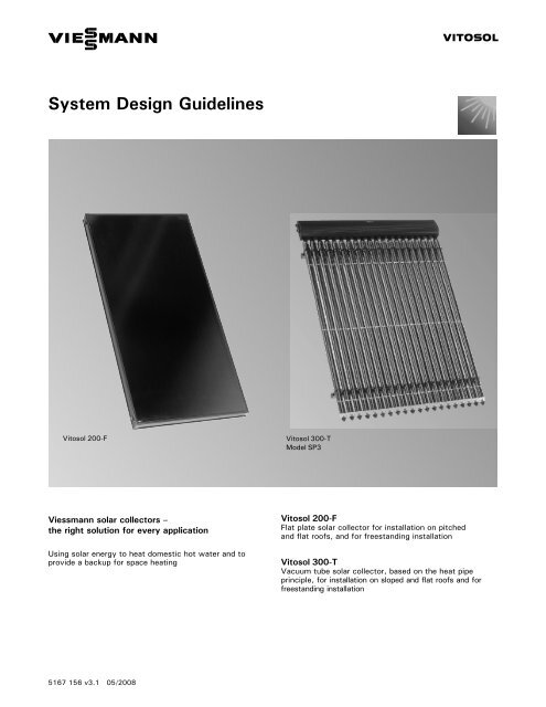
Vitosol 200-F Vitosol 300-T<br />
Model SP3<br />
<strong>Viessmann</strong> solar collectors –<br />
the right solution for every application<br />
Using solar energy to heat domestic hot water and to<br />
provide a backup for space heating<br />
5167 156 v3.1 05/2008<br />
Vitosol 200-F<br />
Flat plate solar collector for installation on pitched<br />
and flat roofs, and for freestanding installation<br />
VITOSOL<br />
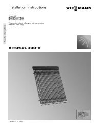
Vitosol 300-T<br />
Vacuum tube solar collector, based on the heat pipe<br />
principle, for installation on sloped and flat roofs and for<br />
freestanding installation
Safety, Installation and Warranty Requirements<br />
2<br />
Safety, Installation and Warranty Requirements<br />
Please ensure that these instructions are read and understood before commencing installation. Failure to comply with the<br />
instructions listed below and details printed in this manual can cause product/property damage, severe personal injury, and/or<br />
loss of life. Ensure all requirements below are understood and fulfilled (including detailed information found in manual<br />
subsections).<br />
H Licensed professional heating<br />
contractor<br />
The installation, adjustment, service,<br />
and maintenance of this equipment<br />
must be performed by a licensed<br />
professional heating contractor.<br />
" Please see section<br />
entitled “Important<br />
Regulatory and<br />
Installation<br />
Requirements”.<br />
H Product documentation<br />
Read all applicable documentation<br />
before commencing installation. Store<br />
documentation near boiler in a readily<br />
accessible location for reference in<br />
the future by service personnel.<br />
" For a listing of<br />
applicable literature,<br />
please see section<br />
entitled “Important<br />
Regulatory and Safety<br />
Requirements”.<br />
H Advice to owner<br />
Once the installation work is<br />
complete, the heating contractor must<br />
familiarize the system<br />
operator/ultimate owner with all<br />
equipment, as well as safety<br />
precautions/requirements, shut-down<br />
procedure, and the need for<br />
professional service annually.<br />
H Warranty<br />
Information contained in<br />
this and related product<br />
documentation must be<br />
read and followed. Failure<br />
to do so renders warranty<br />
null and void.<br />
H Grounding/lightning protection of the<br />
solar system<br />
In the lower part of the building,<br />
install an electrical conductor on the<br />
solar circuit’s piping system in<br />
compliance with local regulations.<br />
Connection of the solar system to a<br />
new or existing lightning protection or<br />
the provision of local grounding should<br />
only be carried out by a licensed<br />
professional, who must take into<br />
account the prevailing conditions on<br />
site.<br />
CAUTION<br />
Observe maximum load and distance<br />
from edge before installing the<br />
substructure to the roof. If necessary,<br />
consult with a structural engineer to<br />
determine if the structure is suitable<br />
for installing solar collectors. The<br />
collectors must be securely mounted<br />
so that the mountings can withstand<br />
intense wind conditions and local<br />
snow loads.<br />
CAUTION<br />
Gloves and eye protection must be<br />
worn when handling solar panels.<br />
CAUTION<br />
Solar panel connection pipes and<br />
solar heating fluid can become hot<br />
enough to cause severe burns.<br />
Extreme caution must be taken if<br />
panels have been in a stagnant<br />
condition (no flow of fluid).<br />
CAUTION<br />
Avoid scratching or sudden shocks to<br />
glass cover of the solar panel.<br />
CAUTION<br />
Never step on collectors or solder in<br />
close proximity to the glass surface<br />
of the solar panel.<br />
H Applicability<br />
Vitosol solar collectors are designed<br />
for use in closed loop heating systems<br />
for domestic hot water heating, space<br />
heating and pool heating via a heat<br />
exchanger. The use of <strong>Viessmann</strong><br />
heat transfer medium “Tyfocor-HTL”<br />
is strongly recommended.<br />
IMPORTANT<br />
Pool water or potable water cannot be<br />
pumped directly through the Vitosol<br />
collectors. Damage to collectors caused<br />
by corrosion, freezing or scaling will<br />
void warranty.<br />
5167 156 v3.1
5167 156 v3.1<br />
Contents<br />
Contents Page<br />
Safety Safety Instructions<br />
Important Regulatory and Installation Requirements<br />
General Information About these Instructions<br />
Product Information<br />
Important Regulatory and Installation Requirements<br />
Basic Principles of Solar Technology Subsidies, Permits and Insurance ................................... 7<br />
Solar Energy ...................................................... 7<br />
HExploiting solar energy ............................................ 7<br />
H Solar radiation ................................................... 8<br />
H Global radiation .................................................. 8<br />
H Exploiting solar energy with collectors .............................. 9<br />
H Influence of alignment, inclination and shade on energy yield ......... 10<br />
H Inclination and orientation of collectors ............................. 11<br />
H Angle of inclination ............................................... 11<br />
Overall <strong>System</strong> Optimisation ....................................... 12<br />
Specification Construction and Function of Collectors ............................. 13<br />
H Vitosol 200-F – flat panel collector ................................. 13<br />
H Vitosol 300-T – vacuum tube collector based on the heat pipe principle 14<br />
Collector Efficiency ................................................ 16<br />
Solar coverage .................................................... 17<br />
Collector Installation and Mounting Details ........................... 18<br />
H Installation options for different collector types ..................... 18<br />
H Vitosol 200-F flat panel collector .................................. 18<br />
H Support weight requirements - Vitosol 300-T ........................ 24<br />
General Installation Instructions ..................................... 26<br />
Notes on Planning and Operation Calculating the Required Absorber Surface Area ...................... 27<br />
H Calculating the absorber surface area and DHW cylinder capacity ..... 27<br />
H Calculating the absorber surface area for space heating .............. 28<br />
Sizing Pipe Diameters and Circulation Pump .......................... 31<br />
H Sizing pipe diameters ............................................ 34<br />
H Installation examples for Vitosol 200-F, models SV2 and SH2 ........ 35<br />
H Collector pressure drop information ................................ 34<br />
H Sizing pipe circulation pump ...................................... 35<br />
H Technical information on the Solar-Divicon .......................... 36<br />
Safety Equipment ................................................. 38<br />
H Liquid capacity of solar heating system components ................. 37<br />
H Diaphragm expansion vessel ...................................... 39<br />
H Technical data for the expansion tank .............................. 43<br />
H Pressure relief valve ............................................. 41<br />
H High limit safety cut-out .......................................... 41<br />
H Thermostatic mixing valve ........................................ 42<br />
Accessories ...................................................... 43<br />
3
Contents<br />
Contents (continued) Page<br />
<strong>System</strong> <strong>Design</strong>s General Information ................................................ 44<br />
H How to implement the installation ................................. 44<br />
<strong>System</strong> <strong>Design</strong> 1 .................................................. 45<br />
H Dual-mode DHW heating with Vitocell-B 100 or Vitocell-B 300<br />
DHW tanks ..................................................... 45<br />
<strong>System</strong> <strong>Design</strong> 2 .................................................. 47<br />
H Dual-mode DHW heating and space heating backup<br />
with heating water storage tank ................................... 47<br />
<strong>System</strong> <strong>Design</strong> 3 .................................................. 50<br />
H Dual-mode DHW heating with two DHW tanks ...................... 50<br />
<strong>System</strong> <strong>Design</strong> 4 .................................................. 53<br />
H Dual-mode DHW and swimming pool water heating ................. 53<br />
<strong>System</strong> <strong>Design</strong> Extensions .......................................... 56<br />
H <strong>System</strong> with bypass circuit ....................................... 56<br />
H Bypass circuit with solar cell ...................................... 56<br />
H <strong>System</strong> with energy-saving mode .................................. 57<br />
Appendix Calculation Example Based on the <strong>Viessmann</strong> ”ESOP” Program ........ 58<br />
H Solar heating systm with dual-coil DHW tank ....................... 58<br />
Glossary ......................................................... 60<br />
4<br />
5167 156 v3.1
5167 156 v3.1<br />
Safety<br />
Important Regulatory and Installation Requirements<br />
Codes<br />
The installation of solar heating<br />
systems might be governed by<br />
individual local rules and regulations for<br />
this type of product, which must be<br />
observed. The installation of this unit<br />
shall be in accordance with local codes.<br />
Always use latest editions of codes.<br />
Mechanical room<br />
Ensure the mechanical room complies<br />
with the requirements of the system<br />
design guideline and/or technical data<br />
manual.<br />
Thesolarstoragetankmustbeinstalled<br />
in a mechanical room which is never<br />
subject to freezing temperatures.<br />
If not in use and danger of freezing<br />
exists in the mechanical room, ensure<br />
water in tank is drained.<br />
Workingontheequipment<br />
The installation, adjustment, service,<br />
and maintenance of this equipment<br />
must be done by a licensed professional<br />
heating contractor who is qualified and<br />
experienced in the installation, service,<br />
and maintenance of solar heating<br />
systems. There are no user serviceable<br />
parts on this equipment.<br />
Ensure main power supply to<br />
equipment, the heating system, and all<br />
external controls has been deactivated.<br />
Take precautions in both instances to<br />
avoid accidental activation of power<br />
during service work.<br />
Technical literature<br />
Literature applicable to all aspects of<br />
the Vitosol:<br />
- Technical Data Manual<br />
- Installation Instructions<br />
- Start-up/Service Instructions<br />
- Operating Instructions<br />
and User’s Information Manual<br />
- <strong>System</strong> <strong>Design</strong> <strong>Guidelines</strong><br />
Please carefully read this manual prior<br />
to attempting installation. Any<br />
warranty is null and void if these<br />
instructions are not followed.<br />
This product must be installed<br />
observing not only the necessary<br />
product literature (see list), but also<br />
all local, provincial/state plumbing and<br />
building codes, as they apply to this<br />
product and all periphery equipment.<br />
For information regarding other<br />
<strong>Viessmann</strong> <strong>System</strong> Technology<br />
componentry, please reference<br />
documentation of the respective<br />
product.<br />
We offer frequent installation and<br />
service seminars to familiarize our<br />
partners with our products. Please<br />
inquire.<br />
The completeness and functionality of<br />
field supplied electrical controls and<br />
components must be verified by the<br />
heating contractor. These include<br />
pumps, valves, air vents, thermostats,<br />
temperature and pressure relief<br />
controls, etc.<br />
Leave all literature at the installation<br />
site and advise the system<br />
operator/ultimate owner where the<br />
literature can be found. Contact<br />
<strong>Viessmann</strong> for additional copies.<br />
5
General Information<br />
6<br />
About these Instructions<br />
Take note of all symbols and notations intended to draw attention to potential hazards or important product<br />
information. These include ”WARNING”, ”CAUTION”, and ”IMPORTANT”. See below.<br />
Product Information<br />
WARNING<br />
Indicates an imminently hazardous<br />
situation which, if not avoided, could<br />
result in substantial product/property<br />
damage, serious injury or loss of life.<br />
CAUTION<br />
Indicates an imminently hazardous<br />
situation which, if not avoided, may<br />
result in minor injury or<br />
product/property damage.<br />
IMPORTANT<br />
Warnings draw your attention to the<br />
presence of potential hazards or<br />
important product information.<br />
Cautions draw your attention to the<br />
presence of potential hazards or<br />
important product information.<br />
Helpful hints for installation, operation<br />
or maintenance which pertain to the<br />
product.<br />
This symbol indicates that additional,<br />
pertinent information is to be found in<br />
the adjacent column.<br />
This symbol indicates that other<br />
instructions must be referenced.<br />
Vitosol 200-F, Models SV2, SH2<br />
Flat panel solar collector with 25 ft. 2 /<br />
2.3 m 2 collector area.<br />
Max. stagnation temperature 430°F /<br />
221°C<br />
Max. operating pressure 87 psig /<br />
6bar<br />
Vitosol 300-T, SP3 Series<br />
Vacuum tube solar collector with 22<br />
and 32 ft. 2 /2and3m 2 collector area.<br />
Max. stagnation temperature 302°F /<br />
150°C<br />
Max. operating pressure 87 psig /<br />
6bar<br />
5167 156 v3.1
5167 156 v3.1<br />
Subsidies, Permits and Insurance<br />
Solar Energy<br />
Exploiting solar energy<br />
Solar heating systems for DHW or<br />
swimming pool heating are subsidised<br />
by many regional and local authorities.<br />
Request information about subsidies<br />
from your local authority.<br />
Further information is available from our<br />
sales offices.<br />
The sun has provided the earth with<br />
light and heat for billions of years.<br />
Without it, our existence on earth<br />
would be impossible.<br />
We have been using the sun’s heat<br />
since time immemorial. In summer, it<br />
heats our buildings directly, while in<br />
winter we make use of solar energy<br />
stored in the form of wood, coal, oil and<br />
gas, to provide heat for our buildings<br />
and domestic hot water.<br />
To protect fuel reserves, the heating<br />
industry has committed itself to finding<br />
more responsible ways of handling<br />
these precious resources, which have<br />
accumulated naturally over millions of<br />
years.<br />
One rational way of achieving this aim is<br />
to make direct use of solar energy by<br />
means of collectors.<br />
Basic Principles of Solar Technology<br />
Your local planning office will be able to<br />
advise you about whether solar heating<br />
systems need planning permission.<br />
<strong>Viessmann</strong> solar collectors are tested<br />
for impact resistance, incl. hail impact,<br />
in accordance with DIN EN 12975-2.<br />
Nevertheless, we would recommend<br />
you include the collectors in your<br />
building insurance, to protect you from<br />
losses arising from any extraordinary<br />
natural phenomenon. Our warranty<br />
excludes such losses.<br />
Thanks to the use of highly<br />
sophisticated collectors and a perfectly<br />
matched overall system, the economic<br />
use of solar energy is no longer a<br />
futuristic vision, but a proven everyday<br />
reality.<br />
Considering that fuel prices will<br />
continue to rise in the years ahead,<br />
investing in a solar heating system can<br />
be viewed as a ”genuine” investment in<br />
the future.<br />
7
Basic Principles of Solar Technology<br />
2<br />
Solar irradiation in Wh/(m x d)<br />
8<br />
Solar Energy (continued)<br />
Solar radiation<br />
Diffused celestial radiation<br />
Direct solar radiation<br />
Wind, rain, snow, convection<br />
Convection losses<br />
Conduction losses<br />
Global radiation<br />
6000<br />
5000<br />
4000<br />
3000<br />
2000<br />
1000<br />
RT<br />
Heat radiation of the absorber<br />
Heat radiation of the glass cover<br />
Useful collector output<br />
Reflection<br />
RT Return<br />
S Supply<br />
S<br />
direct<br />
radiation<br />
diffused<br />
radiation<br />
0<br />
Jan. Feb. March April May June July Aug. Sept. Oct. Nov. Dec.<br />
Solar radiation represents a flow of<br />
energy irradiated uniformly in all<br />
directions by the sun. Of that energy,<br />
an output of 429 Btu/h/ft. 2 or<br />
1.36 kW/m 2 , the so-called solar<br />
constant, hits the outer earth’s<br />
atmosphere.<br />
After penetrating the earth’s<br />
atmosphere, the solar radiation is<br />
reduced by reflection, dispersion and<br />
absorption by dust particles and<br />
gaseous molecules. That portion of this<br />
radiation which passes unimpeded<br />
through the atmosphere to strike the<br />
earth’s surface is known as direct<br />
radiation.<br />
The portion of the solar radiation which<br />
is reflected and/or absorbed by dust<br />
particles and gas molecules and<br />
irradiated back strikes the earth’s<br />
surface indirectly is known as diffused<br />
radiation.<br />
The total radiation striking the earth’s<br />
surface is the global radiation Eg, i.e.,<br />
global radiation = direct radiation +<br />
diffused radiation.<br />
In the latitudes of North America, the<br />
typical global radiation under optimum<br />
conditions (clear, cloudless sky at midday)<br />
amounts to a max. of 317<br />
Btu/h/ft. 2 or 1 000 W/m 2 .<br />
With solar collectors, as much as 75 %<br />
of this global radiation can be utilised,<br />
depending on the type of collector.<br />
5167 156 v3.1
5167 156 v3.1<br />
Solar Energy (continued)<br />
Exploiting solar energy using solar collectors<br />
The useful energy which a collector can<br />
absorb depends on several factors.<br />
The main factor is the total solar energy<br />
available.<br />
Annual global radiation in Canada<br />
Annual global radiation in the United States<br />
The amount of global energy varies<br />
from location to location (see maps<br />
below).<br />
Basic Principles of Solar Technology<br />
The type of collector, as well as its<br />
inclination and orientation, are also very<br />
important (see page 10). If the solar<br />
installation is to be operated<br />
economically, careful dimensioning of<br />
the system components is also<br />
essential.<br />
Btu/ft2 2.5-3kwh/m<br />
/day<br />
2 /day 787-945<br />
3-3.3kwh/m2 /day 945-1040<br />
3.3 - 3.6 kwh/m2 /day 1040-1134<br />
3.6 - 3.9 kwh/m2 /day 1134-1228<br />
3.9 - 4.2 kwh/m2 /day 1228-1323<br />
4.2 - 4.4 kwh/m2 /day 1323-1386<br />
4.4 - 4.7 kwh/m2 /day 1386-1481<br />
>4.7kwh/m2 /day >1481<br />
Btu/ft 2 /day<br />
3-4kwh/m 2 /day 945-1260<br />
4-5kwh/m 2 /day 1260-1575<br />
5-6kwh/m 2 /day 1575-1890<br />
6-7kwh/m 2 /day 1890-2205<br />
Note: Average mean daily global radiation on a south-facing surface tilted at an angle equal to the latitude of the location.<br />
9
Basic Principles of Solar Technology<br />
Solar Energy (continued)<br />
Influence of alignment, inclination and shade on energy yield<br />
Example:<br />
30°; 45° south-west<br />
10<br />
West<br />
North<br />
South<br />
East<br />
Annual<br />
irradiation<br />
in %<br />
Angle of<br />
inclination<br />
Optimum alignment and inclination<br />
The solar generator provides the highest<br />
annual solar yield for a DHW system<br />
whenfacingsouthwithaninclinationof<br />
approx. 30 to 35 degrees<br />
to the horizontal plane. However, the<br />
installation of a solar heating system is<br />
still viable even when the installation<br />
deviates quite significantly from the<br />
above (south-westerly to south-easterly<br />
alignment, 25 to 55 degrees<br />
inclination).<br />
The graph illustrates the loss of yield<br />
resulting from an installation of the<br />
collector array which is less than<br />
perfect. The graph also indicates that a<br />
shallower inclination is more favourable,<br />
if the collector surface cannot be<br />
pointed south. A solar heating system<br />
with a 30º inclination and an alignment<br />
of 45º south-westerly still achieves<br />
95% of its optimum yield. Even with an<br />
east-westerly alignment, you can still<br />
expect 85% with a roof inclination<br />
between 25º and 40º.<br />
A more steeply sloped installation<br />
would be more favourable in winter, but<br />
the system achieves two thirds of its<br />
yield during the summer months. On the<br />
other hand, an angle of inclination less<br />
than 20 degrees should be avoided,<br />
otherwise the solar generator will<br />
become too contaminated, or<br />
snowcovered.<br />
Installing the collector array on different<br />
roofs requires complex hydraulic<br />
interconnections between the individual<br />
collectors.<br />
Every array is equipped with a separate<br />
collector temperature sensor and a<br />
separate pump line.<br />
The increase in energy yield is therefore<br />
offset by the higher installation costs,<br />
resulting in a significantly reduced<br />
cost:benefit ratio.<br />
Shade reduces energy yield<br />
Position and size the collector array so<br />
that the influence of neighbouring<br />
structures, trees, power lines, etc.,<br />
which throw shadows over the array, is<br />
minimised. Also consider how<br />
neighbouring properties will be likely to<br />
develop over a period of 20 years, as<br />
regards additional buildings, plants and<br />
saplings.<br />
5167 156 v3.1
5167 156 v3.1<br />
Solar Energy (continued)<br />
Inclination and orientation of collectors<br />
Angle of inclination<br />
Example:<br />
Deviation from south: 15º east<br />
IMPORTANT<br />
The angle of inclination for Vitosol<br />
300-T collectors must be at least 25º in<br />
order to guarantee circulation of the<br />
evaporator liquid in the heat pipe<br />
Collector plane<br />
Azimuth angle<br />
Basic Principles of Solar Technology<br />
To achieve optimum energy absorption,<br />
the collectors must be oriented towards<br />
the sun.<br />
The angle of inclination and the azimuth<br />
angle are the dimensions used to<br />
determine the orientation of the<br />
collectors.<br />
Angle of inclination α<br />
The angle of inclination a is the angle<br />
between the horizontal and the collector<br />
plane.<br />
For pitched roof installations, the angle of<br />
inclination is determined by the slope of the<br />
roof.<br />
The largest amount of energy can be<br />
captured by the collector’s absorber when<br />
the collector plane is aligned at right<br />
angles to the irradiation of the sun.<br />
Because the angle of irradiation depends<br />
on the time of day and the time of year,<br />
the collector plane should be aligned<br />
according to the position of the sun during<br />
the phase of maximum energy supply.<br />
In practice, angles of inclination of<br />
between 30 and 45º have proven to be<br />
ideal.<br />
For most installations in North America,<br />
for example, an angle of inclination of<br />
between 25 and 70º is advantageous,<br />
depending on the period of use.<br />
Lower angles of inclination are better for<br />
applications where more energy is<br />
required in the summer months (i.e. pool<br />
heating). Higher angles of inclination are<br />
better for applications where more energy<br />
is required in the winter months.<br />
Capturing the maximum amount of energy<br />
throughout the year can be achieved using<br />
an angle of inclination equal to the latitude<br />
of the building site. This is ideal for<br />
domestic hot water heating applications.<br />
Azimuth angle<br />
The azimuth angle describes the deviation<br />
of the collector plane from south; the<br />
collector plane aligned to the south is the<br />
azimuth angle = 0º.<br />
Because solar irradiation is at its most<br />
intensive at midday, the collector plane<br />
should be oriented as closely as possible<br />
to the south. However, deviations from<br />
south up to 45º south-east or south-west<br />
have minimal impact on annual energy<br />
production.<br />
11
Basic Principles of Solar Technology<br />
Overall <strong>System</strong> Optimization<br />
A high-quality solar collector cannot by<br />
itself guarantee the optimum operation<br />
of a solar installation. This depends<br />
more on the complete system solution<br />
as a whole.<br />
<strong>Viessmann</strong> supplies all the components<br />
required for a solar heating system:<br />
12<br />
DHW<br />
I<br />
Solar collector<br />
Solar-Divicon (pumping station)<br />
Overflow container<br />
Expansion vessel<br />
Solar manual filling pump<br />
<strong>System</strong> fill manifold valve<br />
H a control unit that is tailored to the<br />
individual solar heating system,<br />
H a DHW tank incorporating a solar heat<br />
exchanger low inside the tank,<br />
H a preassembled pump station with all<br />
necessary hydraulic components,<br />
H design details aimed at achieving<br />
fast-responding control and therefore<br />
maximum yields from the solar<br />
heating system.<br />
DCW<br />
Brass elbow c/w sensor well<br />
Dual-mode DHW tank<br />
I Tank temperature sensor<br />
Air separator<br />
Solar control unit<br />
Flexible connection pipe<br />
S R<br />
Correctly designed solar heating<br />
systems with well matched system<br />
components can cover 50 to 80 % of<br />
the annual energy demand for DHW<br />
heating in detached and semi-detached<br />
houses.<br />
We will be pleased to assist you with<br />
the design of solar heating systems.<br />
The elements of a solar heating system<br />
areshowninthediagram.<br />
Collector temperature sensor<br />
Fast air-vent, c/w shutoff valve *1<br />
R Return to collector<br />
S Supply from collector<br />
*1 Install at least one air-vent valve (quick-acting air-vent valve or a manual vent valve, see page 43) at the highest point of<br />
the system.<br />
T<br />
T<br />
T<br />
5167 156 v3.1
5167 156 v3.1<br />
Construction and Function of Collectors<br />
Vitosol 200-F flat panel collector<br />
Continuous profiled seal (vulcanised)<br />
Solar glass cover, 3.2 mm thick<br />
Meander-shaped copper pipe<br />
Copper absorber<br />
Melamine resin foam<br />
Technical Data Vitosol 200-F, SV2/SH2<br />
Model Gross Area Absorber<br />
Area<br />
Aperture<br />
Area<br />
Mineral fiber<br />
Aluminum frame sections<br />
Aluminum-zinc bottom panel<br />
Connection pipe<br />
Dimensions Weight<br />
m 2 ft 2 m 2 ft 2 m 2 ft 2 mm in kg lb<br />
SV2 2.51 27.0 2.32 25 2.33 25.1 1056x<br />
2380x90<br />
SH2 2.51 27.0 2.32 25 2.33 25.1 2380x90x<br />
1056<br />
41¾x<br />
93¾x3½<br />
93¾x41¾x<br />
x3½<br />
Specification<br />
Vitosol 200-F flat plate solar collector is<br />
available as:<br />
H Vertical version Model SV2 and<br />
horizontal version Model SH2, each<br />
offering 2.3 m 2 /25ft 2 absorber<br />
surface.<br />
The main component of Vitosol 100 is<br />
the Sol-Titanium coated copper<br />
absorber.<br />
It ensures high absorption of solar<br />
radiation and low emission of thermal<br />
radiation. A copper pipe through which<br />
the heat transfer medium flows is fitted<br />
to the absorber. The heat transfer<br />
medium channels the absorber heat<br />
through the copper pipe.<br />
The meander-shaped direct flow<br />
absorber of models SV2 and SH2<br />
provides an extremely even flow<br />
through each individual collector in the<br />
collector arrays.<br />
The absorber is surrounded by a highly<br />
insulated collector housing which<br />
minimises collector heat losses. The<br />
high quality thermal insulation provides<br />
temperature stability and is free from<br />
gas emissions.<br />
The cover comprises a solar glass panel.<br />
The glass has a very low iron content,<br />
thereby reducing reflection losses.<br />
The collector housing comprises a<br />
powder-coated aluminium frame<br />
(recycled aluminium), within which the<br />
solar glass panel is permanently sealed.<br />
Model SV2 and SH2<br />
Up to twelve collectors can be joined to<br />
form a single collector array. For this<br />
purpose, the standard delivery includes<br />
flexible connection pipes, sealed with<br />
O-rings.<br />
A general connection kit with clamping<br />
ring connections enables the collector<br />
array to be readily attached to the pipes<br />
of the solar circuit.<br />
The collector temperature sensor is<br />
installed in the solar circuit flow via a<br />
sensor well set.<br />
52 115<br />
52 115<br />
13
Specification<br />
Construction and Function of Collectors (continued)<br />
Vitosol 300-T vacuum tube collector<br />
14<br />
Evacuated glass tube<br />
Heat pipe<br />
Absorber<br />
Technical Data Vitosol 300-T, 2m 2 /3m 2<br />
Model Gross Area Absorber<br />
Area<br />
Aperture<br />
Area<br />
Condenser<br />
Double pipe heat exchanger<br />
Dimensions Weight<br />
m 2 ft 2 m 2 ft 2 m 2 ft 2 mm in kg lb<br />
2m 2 2.83 30.5 2.05 22 2.11 22.7 1419x<br />
1996x<br />
122<br />
3m 2 4.24 45.6 3.07 33 3.17 34.1 2126x<br />
1996x<br />
122<br />
55¾x<br />
78½x<br />
4¾<br />
83¾x<br />
78½x<br />
4¾<br />
45 99<br />
68 150<br />
Vitosol 300-T vacuum tube collectors<br />
areavailableintwotypes:<br />
20 tube version,<br />
30 tube version<br />
The tube shape gives the collector great<br />
stability and high impact resistence.<br />
Re-evacuation of the tubes is not<br />
necessary as the tubes have a<br />
permanent airtight seal.<br />
The vacuum in the glass tubes ensures<br />
optimum heat insulation. Convection<br />
losses between the glass tube and the<br />
absorber are almost completely<br />
eliminated. This enables the utilisation<br />
of even low radiation levels (diffused<br />
radiation). The performance of the<br />
collector does not drop off as<br />
significantly in cold weather as a flat<br />
plate collector. On average,<br />
approximately 30% to 50% higher<br />
annual solar energy gain than flat plate<br />
collectors can be expected.<br />
Built into each vacuum tube is a<br />
Sol-Titanium coated copper absorber. It<br />
is a highly selective surface that<br />
ensures high absorption of solar<br />
radiation and low emission of thermal<br />
radiation.<br />
A heat pipe filled with an evaporator<br />
liquid is arranged on the absorber. The<br />
heat pipe is connected to the condenser<br />
via a flexible coupling. The condenser is<br />
mounted in a double pipe heat<br />
exchanger.<br />
This involves a so-called ”dry<br />
connection”, i.e. pipes can be rotated or<br />
replaced even when the installation is<br />
filled and under pressure.<br />
Heat is transferred from the absorber to<br />
the heat pipe. This lets the liquid<br />
evaporate. The vapour then rises to the<br />
condenser.<br />
The heat is transferred to the passing<br />
heat transfer medium by the<br />
double-pipe heat exchanger containing<br />
the condenser which causes the vapour<br />
to condense. The condensate flows<br />
back into the heat pipe and the process<br />
is repeated.<br />
Please note:<br />
Theangleofinclinationmustbeatleast<br />
25º to guarantee circulation of the<br />
evaporator liquid inside the heat<br />
exchanger.<br />
5167 156 v3.1
5167 156 v3.1<br />
Construction and Function of Collectors (continued)<br />
Vitosol 300-T (continued)<br />
Legend<br />
102mm /<br />
4”<br />
Groove for retaining clip<br />
Specification<br />
Absorber surface areas of up to 6 m 2<br />
can be joined to form a single collector<br />
array. For this purpose, the standard<br />
delivery includes flexible connection<br />
pipes, sealed with O-rings.<br />
A connection kit with clamping ring<br />
connections enables the collector array<br />
to be readily connected to the pipes of<br />
the solar circuit.<br />
The collector temperature sensor is<br />
installed in a sensor mounting on the<br />
flow pipe in the connection housing of<br />
the collectors.<br />
15
Specification<br />
Collector Efficiency<br />
Some of the solar radiation striking the<br />
glassofthecollectorsis”lost”dueto<br />
reflection and absorption. The optical<br />
efficiency ηo takes these losses into<br />
account.<br />
When the collectors heat up, they<br />
transfer heat to the environment as the<br />
result of conduction, radiation and<br />
convection. These thermal losses are<br />
allowed for by the heat loss factors k1<br />
and k2 .<br />
16<br />
The heat loss factors and optical<br />
efficiency combine to form the collector<br />
efficiency curve which can be<br />
calculated on the basis of the following<br />
formula:<br />
η = ηo − k1 ⋅ ∆T<br />
− k2 ⋅<br />
Eg<br />
∆T2<br />
Eg<br />
Eg= radiation intensity (W/m 2 )<br />
∆ T=Temperature difference between<br />
ambient air and collector fluid ºC<br />
Collector type Opt. efficiency Heat loss factors Spec. thermal<br />
level<br />
capacity<br />
*1 i %<br />
kJ/( 2 ηo K)<br />
*1 in % k1 in<br />
W/(m2 · K)<br />
k2 in<br />
W/(m2 · K2 p y<br />
)<br />
kJ/(m2 · K)<br />
Vitosol 200-F 79.3<br />
3.95<br />
0.0122 6.4<br />
Vitosol 300-T 82.5<br />
1.19<br />
0.009 5.4<br />
*1 ηo basedonabsorberarea<br />
H<br />
0.9<br />
Efficiency<br />
0.8<br />
0.7<br />
0.6<br />
0.5<br />
0.4<br />
0.3<br />
0.2<br />
0.1<br />
0<br />
0 10 20 30 40 50 60 70 80 90 100<br />
Temperature difference in degrees C between ambient air and collector fluid<br />
Vitosol 300-T<br />
Vitosol 200-F<br />
If the difference between the collector<br />
and ambient temperature is zero, the<br />
collector loses no heat to the<br />
environment, and the efficiency η is at<br />
its maximum level; this is known as the<br />
optical efficiency ηo.<br />
The thermal capacity is a measure of<br />
the thermal inertia of the collector, and<br />
shows the response behaviour of the<br />
collector when heating and cooling. A<br />
low thermal capacity is of advantage<br />
with wide ranging temparature and<br />
weather conditions typical in northerly<br />
climates.<br />
The table below lists comparative<br />
values for the optical efficiency and the<br />
heat loss factors as tested in European<br />
certification labs.<br />
Vitosol 200-F and 300-T are both<br />
tested and certified in North America to<br />
SRCC OG-100.<br />
5167 156 v3.1
5167 156 v3.1<br />
Solar Coverage<br />
Vitosol 200-F<br />
Absorber surface in m 2 Absorber surface in m 2<br />
0 13 26 40 53 66 79 92<br />
ltrs/day<br />
106 USG/day<br />
Vitosol 300-T<br />
DHW consumption<br />
DHW consumption<br />
Reference system<br />
100 litres/day<br />
300 litres/day<br />
400 litres/day<br />
Collector inclination 30°<br />
Collector inclination 60°<br />
Westerly orientation<br />
South-west orientation<br />
*1<br />
Vacuum tubes<br />
Hannover<br />
Freiburg<br />
USG/day<br />
0 13 26 40 53 66 79 92<br />
ltrs/day<br />
106 USG/day<br />
Influence of various parameters on solar coverage<br />
*1 For comparable absorber surface area.<br />
0 20 40 60 80<br />
Solar cover rate in %<br />
45<br />
45<br />
52<br />
56<br />
55<br />
62<br />
61<br />
61<br />
69<br />
76<br />
77<br />
Specification<br />
The solar coverage value indicates<br />
what percentage of the energy required<br />
annually for domestic hot water<br />
applications can be covered by the solar<br />
heating system.<br />
The absorber surface area should be<br />
sized so that the ”production” of<br />
surplus heat is just about avoided<br />
during the summer months.<br />
The higher the solar cover rate, the<br />
lower the efficiency, since a high cover<br />
rate has the effect of raising the<br />
temperature level of the solar circuit.<br />
This results in increased heat losses<br />
and lower seasonal efficiency.<br />
The diagrams show the coverage values<br />
that can be achieved with the various<br />
collector types, based on<br />
H the meteorological records for a<br />
typical location at 49° latitude,<br />
H south-facing roofs,<br />
H a roof pitch of 45º and<br />
H a DHW temperature of 113°F / 45ºC<br />
in the standby tank.<br />
This data represents approximate guide<br />
values.<br />
Note:<br />
Solar fractions will be higher for<br />
locations in southern parts of the USA<br />
due to higher levels of radiation.<br />
Reference system:<br />
H 4-person household with hot water<br />
consumption of 53 USG/day / 200<br />
litres/day<br />
H 2 Vitosol 200-F collectors, model<br />
SV2 and SH2<br />
H 45º roof inclination<br />
H South-facing roof orientation<br />
H Dual-mode DHW cylinder, 300 litres<br />
H Meteorological records for a typical<br />
location at 49° latitude<br />
The bars indicate the expected<br />
coverage values for deviations from the<br />
reference system.<br />
17
Specification<br />
Collector Installation and Mounting<br />
Installation options for different collector types<br />
Sloped roofs - rooftop installation<br />
Required roof area<br />
18<br />
<strong>Viessmann</strong> offers universal mounting<br />
systems to simplify installation. The<br />
mounting systems are suitable for<br />
virtually all forms of roofs, as well as<br />
installation on flat roofs or ground<br />
mounted free-standing installations.<br />
Fitting Collector type<br />
Pitched roofs A Vitosol 200-F, model SV2<br />
Vitosol 300-T<br />
B Vitosol 200-F, model SH2<br />
Flat roofs C Vitosol 200-F, model SV2, SH2<br />
Vitosol 300-T<br />
Freestanding installation D Vitosol 200-F, model SV2, SH2<br />
Vitosol 300-T<br />
Collector Type A mm A in B mm B in<br />
Vitosol 200-F,<br />
type SV2 2380 93 3/4 1056 + 16* 1 41 5/8 + 5/8* 1<br />
Vitosol 200-F,<br />
type SH2 1056 41 5/8 2380 + 16* 1 93 3/4 + 5/8* 1<br />
Vitosol 300-T,<br />
type SP3, 2m2 2031 80 1418 + 102* 1 55 3/4 + 4* 1<br />
Vitosol 300-T,<br />
type SP3, 3m2 2031 80 2127 + 102* 1 83 3/4 + 4* 1<br />
*1 Add this value for every additional collector.<br />
5167 156 v3.1
5167 156 v3.1<br />
Collector Installation and Mounting (continued)<br />
Vitosol 200-F flat panel collector<br />
Flat collectors are ideally suited for<br />
domestic hot water and swimming pool<br />
heating applications.<br />
Both vertical and horizontal types are<br />
suitable for installation on pitched roofs.<br />
The selection of method of installation<br />
is influenced by the structural<br />
characteristics of the building.<br />
Sloped Roofs Installation Details<br />
c<br />
Collector<br />
Lag bolt<br />
Mounting rail<br />
Roof bracket<br />
Model SH2 has been specially designed<br />
for installation on flat roofs and for<br />
freestanding installation.<br />
<strong>Viessmann</strong> offers a universal fastening<br />
system to simplify installation. The<br />
fastening system is suitable for virtually<br />
all forms of roof and roofing.<br />
Collector Dimension a b c<br />
Model SV2<br />
Model SH2<br />
a<br />
inches<br />
mm<br />
inches<br />
mm<br />
b<br />
93¾<br />
2 380<br />
41¾<br />
1 138<br />
74¾ - 82½<br />
1 900 - 2 100<br />
19½ - 35½<br />
500 - 900<br />
3½<br />
89<br />
3½<br />
89<br />
Specification<br />
Installation kits are available for<br />
installing collectors on flat roofs.<br />
An engineering evaluation is required to<br />
establish additional superimposed loads<br />
from wind or snow, as described in the<br />
local building code. Retain the services<br />
of a professional structural engineer to<br />
calculate additional live loads due to the<br />
installation of solar collectors on the<br />
roof.<br />
40<br />
10<br />
19
Specification<br />
Collector Installation and Mounting (continued)<br />
Flat roof installation<br />
The collectors should be installed with<br />
an angle of inclination of 35 º to 45 º if<br />
the load capacity of the roof allows<br />
this. Maintain a minimum distance of<br />
2m/6ft from the roof edge in all<br />
installations.<br />
Outsideofthisareayoumay<br />
experience significant increases in wind<br />
turbulance. The system will also be<br />
hard to access if modifications are<br />
required. If the roof size dictates a<br />
modification of the array distribution,<br />
ensure that arrays of the same size are<br />
created.<br />
Determining the collector row distance<br />
“z”<br />
When installing several collector rows in<br />
sequence, exact dimensions (dimension<br />
“z”) must be maintained to prevent<br />
unwanted shade.<br />
Determine angle of the sun β.<br />
Collector row distance ”z” (all<br />
dimensions in mm)<br />
20<br />
l<br />
α<br />
z = Collector row distance<br />
l = Collector height<br />
(see page 13 and 14)<br />
z<br />
β<br />
A collector system must be secured by<br />
additional weights against slippage and<br />
lifting (see table on the following page).<br />
Slippage is the movement of the<br />
collectors on the roof surface due to<br />
wind, because of insufficient friction<br />
between the roof surface and the<br />
collector system.<br />
H Collectors secured against slippage<br />
require more ballast weight, but no<br />
additional attachment to the roof or<br />
substructure.<br />
This should be chosen so that the<br />
midday sun on Dec. 12 can fall onto the<br />
collector without creating shade.<br />
In North America, this angle is<br />
dependent upon latitude and is between<br />
13 º (Edmonton) and 41 º (Miami).<br />
H Collectors secured against lifting<br />
require less ballast weight, but<br />
additional attachment to the roof or<br />
building structure with wires, cables<br />
or other sufficient means.<br />
Example<br />
Boston is located approx. 42.5 º latitude.<br />
Angle of the sun β= 90 º -23.5 º -latitude<br />
(23.5 º should be accepted as the<br />
constant)<br />
90 º -23.5 º -42.5 º =24 º<br />
l · sin (180º - ( α+ β ))<br />
z =<br />
sin β<br />
Vitosol 200-F, type SV2<br />
l = 2380mm<br />
α= 45 º β =24 º (Boston)<br />
2385mm 0 sin (180º - 69 º )<br />
z =<br />
sin 24º<br />
z = 5474mm<br />
Collector type Vitosol 200-F Vitosol 300-T<br />
Type SV2<br />
Angle of inclination α<br />
l<br />
α<br />
β<br />
α<br />
= Collector angle of inclination<br />
= Angle of the sun<br />
Type SH2<br />
Angle of inclination α<br />
Angle of inclination α<br />
Angle of sun β 35º 45º 35º 45º 35º 45º 55º<br />
15.0º 7059 7880 3140 3550 5991 6772 7349<br />
17.5º 6292 7035 2799 3130 5340 5970 6419<br />
20.0º 5712 6320 2541 2812 4848 5363 5716<br />
22.5º 5256 5758 2338 2561 4461 4886 5164<br />
25.0º 4887 5303 2174 2359 4148 4500 4716<br />
27.5º 4582 4926 2038 2191 3888 4180 4346<br />
Min. 6 ft/<br />
2m<br />
Roof edge<br />
Collector<br />
array<br />
Min. 6 ft/<br />
2m<br />
5167 156 v3.1
5167 156 v3.1<br />
Collector Installation and Mounting (continued)<br />
Vitosol 200-F flat panel collector (continued)<br />
Please refer to Vitosol 200-F Installation<br />
instructions for additional information on<br />
collector mounting on 5285 710.<br />
A<br />
An evaluation by a professional<br />
structural engineer is required to<br />
calculate additional live loads due to the<br />
installation of solar collectors on a roof.<br />
Vitosol 200-F, type SV2 and SH2<br />
Collector angle of inclination - 25 º or 45 º<br />
Ballast to be applied and maximum load on the substructures of flat roofs to DIN 1055<br />
Specification<br />
Collector angle of inclination 25º 45º<br />
Ballast against slippage* 1 Ballast against lifting* 1 Ballast against slippage Ballast against lifting<br />
Installation height above ground m up 8 20 up 8 20 up 8 20 up 8 20<br />
to to to to to to to to to to to to<br />
Ballast to be applied<br />
8 20 100 8 20 100 8 20 100 8 20 100<br />
Type SV2 kg 315 554 793 144 304 465 508 842 1213 128 224 346<br />
Type SH2 kg 323 561 800 155 315 476 492 845 1198 132 254 375<br />
* 1 See description on page 20.<br />
Collector supports<br />
The collector supports are pre-assembled. They consist of foot support A, bearing supports and adjustment pieces. The<br />
upper adjustment pieces contain holes for adjusting the angle of inclination.<br />
Connection cross ties are required for 1 to 6 collectors connected in a series.<br />
A Foot support<br />
IMPORTANT<br />
Type SV2<br />
Foot support hole dimensions<br />
80<br />
11<br />
50<br />
75<br />
100 1620<br />
1795<br />
Type SH2<br />
Foot support hole dimensions<br />
80<br />
11<br />
50<br />
75<br />
100 722<br />
897<br />
21
Specification<br />
Collector Installation and Mounting (continued)<br />
Vitosol 200-F<br />
Installation on substructures<br />
22<br />
X<br />
Y<br />
X<br />
* 1 For calculating dimension “z”, see page 20<br />
Installation with ballast<br />
X<br />
Y<br />
X<br />
* 1 For calculating dimension “z”, see page 20<br />
A<br />
A<br />
Z* 1<br />
Z* 1<br />
A Connection cross ties<br />
A Connection cross ties<br />
Collector type x mm x in y mm y in<br />
SV2 590 23 1/4 481 19<br />
SH2 1920 75 5/8 481 19<br />
5167 156 v3.1
5167 156 v3.1<br />
Collector Installation and Mounting (continued)<br />
Vitosol 300-T sloped roof installation details<br />
1600mm /<br />
63”<br />
Collector<br />
Roof bracket<br />
Roof joist<br />
Collector installation rail with tube mountings<br />
Roof sheathing complete with shingles<br />
Lag bolt<br />
1650mm /<br />
65”<br />
230mm /<br />
9”<br />
340mm /<br />
13.4”<br />
2m 2 version 1419mm/55 3 /4” 102mm / 4” 3m 2 version 2126mm/83 3 /4”<br />
Deviations from south<br />
can be compensated by<br />
axial rotation of the<br />
vacuum tubes.<br />
Specification<br />
23
Specification<br />
Collector Installation and Mounting (continued)<br />
Flat roof support weight requirements - Vitosol 300-T<br />
Collector angle of inclination of 25º<br />
Weight of supports<br />
Installation height above ground ft.<br />
m<br />
Weight of supports<br />
* 1 See description on page 20.<br />
A<br />
24<br />
lbs per support A<br />
kg per support A<br />
lbs per support B<br />
kg per support B<br />
Secured against slippage* 1 Secured against lifting* 1<br />
up to 26<br />
up to 8<br />
2m2 Version<br />
168<br />
76<br />
225<br />
102<br />
3m 2<br />
Version<br />
256<br />
116<br />
342<br />
155<br />
Support A<br />
Support B<br />
Model 2m 2 Version 3m 2 Version<br />
Dimension X inches<br />
mm<br />
Dimension Y inches<br />
mm<br />
Surface area (X x Y) ft. 2<br />
m 2<br />
Weight of lbs<br />
collector kg<br />
B<br />
76¼<br />
1940<br />
56¾<br />
1440<br />
30<br />
2.80<br />
99<br />
45<br />
76¼<br />
1940<br />
84½<br />
2149<br />
44½<br />
4.15<br />
150<br />
68<br />
26 to 66<br />
8to20<br />
2m2 Version<br />
284<br />
129<br />
392<br />
178<br />
3m 2<br />
Version<br />
430<br />
195<br />
593<br />
269<br />
up to 26<br />
up to 8<br />
2m2 Version<br />
57<br />
26<br />
141<br />
64<br />
3m 2<br />
Version<br />
90<br />
41<br />
220<br />
100<br />
26 to 66<br />
8to20<br />
2m2 Version<br />
112<br />
51<br />
276<br />
125<br />
3m 2<br />
Version<br />
176<br />
80<br />
421<br />
191<br />
5167 156 v3.1
5167 156 v3.1<br />
Collector Installation and Mounting (continued)<br />
Flat roof support weight requirements - Vitosol 300-T (continued)<br />
Collector angle of inclination of 45º<br />
Weight of supports<br />
Installation height above ground ft.<br />
m<br />
Weight of supports<br />
A<br />
lbs per support A<br />
kg per support A<br />
lbs per support B<br />
kg per support B<br />
Secured against slippage Secured against lifting<br />
up to 26<br />
up to 8<br />
2m2 Version<br />
H20<br />
225<br />
102<br />
377<br />
171<br />
3m 2<br />
Version<br />
344<br />
156<br />
564<br />
256<br />
Support A<br />
Support B<br />
Model 2m 2 Version 3m 2 Version<br />
Dimension X inches<br />
mm<br />
Dimension Y inches<br />
mm<br />
Surface area (X x Y) ft. 2<br />
m 2<br />
Weight of lbs<br />
collectors kg<br />
B<br />
60¼<br />
1530<br />
56¾<br />
1440<br />
24<br />
2.20<br />
99<br />
45<br />
60¼<br />
1530<br />
84½<br />
2149<br />
35<br />
3.27<br />
150<br />
68<br />
26 to 66<br />
8to20<br />
2m2 Version<br />
390<br />
177<br />
633<br />
287<br />
3m 2<br />
Version<br />
586<br />
266<br />
948<br />
430<br />
up to 26<br />
up to 8<br />
2m2 Version<br />
--<br />
--<br />
161<br />
73<br />
3m 2<br />
Version<br />
--<br />
--<br />
245<br />
111<br />
Specification<br />
26 to 66<br />
8to20<br />
2m2 Version<br />
--<br />
--<br />
302<br />
137<br />
3m 2<br />
Version<br />
--<br />
--<br />
454<br />
206<br />
25
Specification<br />
General Installation Instructions<br />
26<br />
H Vitosol solar collectors are hailproof.<br />
Nevertheless we recommend to<br />
include bad weather and hail damage<br />
coverage into your home owners<br />
insurance package. Our warranty does<br />
not cover such damages.<br />
H Please observe local building code<br />
guidelines for maximum load<br />
restrictions on the substructure and<br />
for necessary distance to roof edge.<br />
H Make sure to remove snow off<br />
collectors if more than 20” / 50 cm<br />
have accumulated.<br />
H Mount collectors carefully, so that<br />
even during storm and bad weather<br />
mounting clamps can absorb any<br />
tension.<br />
H An access door or skylight should be<br />
provided in the roof in the vicinity of<br />
the collectors to facilitate inspection<br />
and maintenance work.<br />
H When there is a relatively large<br />
distance between the collector panel<br />
and the roof ridge, a snow board must<br />
be installed above the collector panel<br />
in regions where heavy snowfalls can<br />
be expected.<br />
H Filling the solar heating systems with<br />
<strong>Viessmann</strong> “Tyfocor-HTL” heat<br />
transfer medium is highly<br />
recommended. Other heat transfer<br />
fluids may be suitable if they have the<br />
same temperature range (-35ºC /<br />
-31ºF to 170ºC / 338ºF) and are<br />
non-toxic.<br />
H Use high temperature insulation<br />
materials. In pump idle mode and with<br />
strong solar irradiation, collectors<br />
could reach an idle temperature of<br />
over 200 º C / 392ºF. Protect pipe<br />
insulation and sensor cables against<br />
attack by birds and animals.<br />
H Grounding and lightning protection of<br />
the solar heating system<br />
An electrically conductive connection<br />
ofthepipeworksystemofthesolar<br />
circuit should be implemented in the<br />
lower part of the building in<br />
accordance with local regulations.<br />
Connection of the collector system to<br />
a new or existing lightning protection<br />
system or the provision of local<br />
grounding should only be carried out<br />
by a licensed professional, taking local<br />
conditions into account.<br />
5167 156 v3.1
5167 156 v3.1<br />
Calculating the Required Absorber Surface Area<br />
Calculating the absorber surface area and DHW tank capacity<br />
Absorber surface area<br />
Estimates based on meteorological<br />
conditions such as annual global<br />
radiation, cloud cover etc. are<br />
sufficiently accurate for practical<br />
purposes. In order to obtain a<br />
comprehensive summary of the solar<br />
coverage for domestic hot water<br />
heating, it is recommended that this<br />
estimate should form the basis of a<br />
calculation carried out using a solar<br />
computer simulation. <strong>Viessmann</strong> can<br />
provide design support and computer<br />
simulations upon request. Contact your<br />
local <strong>Viessmann</strong> sales representative.<br />
The cover rate determined by this<br />
program should be 50 to 60 % for<br />
relatively small systems (detached<br />
house), and at least 40 % for larger<br />
systems (apartment block).<br />
Guide values for estimating the required<br />
absorber surface area can be drawn<br />
from the table on page 30.<br />
The absorber surface area calculated on<br />
the basis of this table has proved to be<br />
accurate in practice.<br />
Typical Solar Storage and Collector Selection<br />
# People<br />
in household<br />
2<br />
3-4<br />
5-6<br />
Daily DHW Demand<br />
@ 50ºC/120ºF<br />
120L<br />
32 gal.<br />
180-240L<br />
48-63 gal.<br />
300-360L<br />
79-95 gal.<br />
The basis for designing a solar DHW<br />
heating system is the DHW daily<br />
demand. It can be estimated based on<br />
the following table:<br />
Residential<br />
properties *1<br />
High demands<br />
Average demands<br />
Low demands<br />
Solar Tank<br />
Capacity<br />
200L<br />
53 gal.<br />
300L<br />
79 gal.<br />
450L<br />
120 gal.<br />
DHW Demand<br />
Vp<br />
litres/(d · person)<br />
For DHW temps<br />
temps.<br />
45ºC 60ºC<br />
50 - 80 35-56<br />
30- 50 21-35<br />
15 - 30 11-21<br />
Notes on Planning and Operation<br />
DHW tank capacity (solar storage)<br />
The following values can be used as a<br />
basis for calculating the cylinder<br />
storage capacity:<br />
The total available solar DHW tank<br />
capacity (dual-coil tank or preheating<br />
tank) should be sized on the basis of<br />
1.5 to 2 times the daily requirements.<br />
For fluctuating DHW demand use larger<br />
storage (daily demand x2). For relatively<br />
constant demand use value 1.5.<br />
The minimum solar storage tank volume<br />
should be based on 50 liter/m 2 /<br />
1.25gal/ft 2 collector absorber area.<br />
Vitosol 200-F Flat Plate<br />
Collectors SH2/SV2<br />
1 1x2m 2<br />
2 1x3m 2<br />
Vitosol 300-T<br />
Tube Collectors<br />
3 1x2m 2+ 1x3m 2<br />
27
Notes on Planning and Operation<br />
Calculating the Required Absorber Surface Area<br />
<strong>System</strong> for space heating backup - DHW cylinder and collector<br />
Energy requirement or gain (%)<br />
100<br />
75<br />
50<br />
25<br />
0<br />
Jan.<br />
Feb.<br />
Mar.<br />
Apr.<br />
May<br />
Jun.<br />
Jul.<br />
Aug.<br />
Sep.<br />
Oct.<br />
Nov.<br />
Dec.<br />
A Space heating requirement for one house (typical construction)<br />
B Space heating requirement for one low energy house<br />
C Hot water requirement<br />
D Solar energy yield at 5 m 2 absorber surface (2 flat collectors)<br />
E Solar energy yield at 15 m 2 absorber surface (6 flat collectors)<br />
Concentrating exclusively on the central<br />
heating demand can lead to problematic<br />
oversizing of the system.<br />
For low energy houses (heat demand<br />
less than 50 kWh/(m 2 p.a.), solar<br />
coverage of 20 to 25% refers to the<br />
total energy demand, incl. provision for<br />
DHW heating.<br />
28<br />
E<br />
D<br />
A<br />
B<br />
C<br />
For buildings with a higher energy<br />
demand the coverage drops lower.<br />
Use the <strong>Viessmann</strong> ESOP calculation<br />
program when making sizing<br />
calculations.<br />
Max. connectable collector area when<br />
using Vitocell tanks must follow the<br />
chart on page 31.<br />
The period when the greatest amount of<br />
solar energy is available does not<br />
coincide with the time when the most<br />
heat is required.<br />
While the heat consumption for DHW<br />
heating is relatively constant<br />
throughout the year, only very little<br />
solar energy is available at the times<br />
when the heat demand for central<br />
heating is at its highest (see diagram).<br />
A relatively large absorber area is<br />
required to provide central heating<br />
backup. In summer, this can result in<br />
stagnation in the solar circuit. <strong>System</strong>s<br />
for heating backup require additional<br />
storage tanks and controls.<br />
The basis for sizing a solar heating<br />
system for central heating backup is the<br />
space heating demand of the building<br />
during spring, autumn and in winter, as<br />
well as the heating demand in summer<br />
(i.e. the demand for DHW heating).<br />
Heat demand in summer, e.g to avoid<br />
condensation in cellars, to use<br />
underfloor heating in bathrooms,<br />
increases the demand. For efficient<br />
operation of a solar central heating<br />
backup, the collector area should be 2<br />
to 2.5 times larger than the DHW heat<br />
demand in summer requires.<br />
To avoid excessive summer time<br />
temperature stagnation avoid using<br />
collector areas greater than 3 times<br />
whatwouldbeusedforDHW<br />
requirements only.<br />
5167 156 156 v3.1
5167 156 v3.1<br />
Calculating the Required Absorber Surface Area (continued)<br />
Swimming pool water heating system - heat exchanger and collector<br />
Open-air swimming pools<br />
Open-air swimming pools are mainly<br />
used between May and September [in<br />
northern USA]. The energy demand<br />
required depends mainly on the leakage<br />
rate, evaporation, loss (water must be<br />
replenished cold) and the transmission<br />
heat loss. Through using a cover, the<br />
evaporation and consequently the<br />
energy demand of the pool is reduced<br />
to a minimum. The largest energy input<br />
comes direct from the sun, which<br />
shines onto the pool surface. Therefore<br />
the pool has a ”natural” base<br />
temperature which can be shown in the<br />
adjacent diagram as an average pool<br />
temperature over the operating time.<br />
A solar heating system in no way alters<br />
this typical temperature pattern. The<br />
solar application leads to a definite<br />
increase in the base temperature.<br />
Subject to the ratio between the pool<br />
surface and the collector area, a<br />
different temperature can be reached.<br />
The adjacent diagram shows with<br />
which ratio of aperture or absorber area<br />
to the pool surface what average<br />
temperature increase can be reached.<br />
This ratio is independent of the collector<br />
type used due to the comparably low<br />
collector temperatures and the<br />
operating period (summer). For this<br />
reason, unglazed collectors are most<br />
often used for outdoor pools.<br />
Indoor swimming pools<br />
Indoor swimming pools generally have a<br />
higher target temperature than open-air<br />
pools and are used throughout the year.<br />
If, over the course of the year, a<br />
constant pool temperature is required,<br />
indoor swimming pools must be heated<br />
in dual-mode. To avoid sizing errors, the<br />
energy demand of the pool must be<br />
measured. For this, suspend heating the<br />
water for 48 hours and determine the<br />
temperature at the beginning and end of<br />
the test period. The daily energy<br />
demand can therefore be calculated<br />
from the temperature difference and the<br />
capacity of the pool. For new builds,<br />
the heat demand of the swimming pool<br />
must be calculated.<br />
Note<br />
Revising and maintaining the pool<br />
temperature at a higher base level using<br />
a conventional heating system does not<br />
alter this ratio. However, the pool will<br />
be heated up much more quickly.<br />
20<br />
15<br />
10<br />
5<br />
0<br />
Jan Feb MarApr May Jun JulAug Sep Oct Nov Dec<br />
Average pool temperature in 0C25<br />
Average temperature increases<br />
in degrees C/day<br />
8<br />
7<br />
6<br />
5<br />
4<br />
3<br />
2<br />
1<br />
0<br />
0.1 0.2 0.3 0.4 0.5 0.6 0.7 0.8 0.9 1.0 1.1 1.2<br />
Ratio-absorber area to the pool surface<br />
(open-air swimmimg pool)<br />
On a summer day (clear skies), a<br />
collector system used to heat a<br />
swimming pool in northern USA<br />
produces energy of approx. 4.5kWh/m2<br />
absorber area.<br />
Calculation example for Vitosol 200-F<br />
Pool surface: 36 m 2<br />
Average pool depth: 1.5m<br />
Pool capacity: 54m 3<br />
Temperature loss<br />
on 2 days: 2ºC<br />
Daily energy demand:<br />
kWh<br />
54m3⋅1K⋅1.16 = 62.6kWh<br />
Km 3<br />
Notes on Planning and Operation<br />
Collector area:<br />
Location Boston<br />
40m 2 Upper surface<br />
1.5m deep<br />
protected position<br />
covered at night<br />
62.6 kWh<br />
4.5 kWh/m 2<br />
This corresponds to 6 collectors.<br />
=13.9m 2<br />
For a first approximation (cost<br />
estimate), an average temperature loss<br />
of 1C/day can be used. With an average<br />
pool depth of 1.5m an energy demand<br />
of 1.74kWh/day is required to maintain<br />
the base temperature. It is therefore<br />
sensible to use approx. 0.4m 2 absorber<br />
area per m 2 of pool surface.<br />
29
Notes on Planning and Operation<br />
Calculating the Required Absorber Surface Area (continued)<br />
Guide values for sizing solar heating systems (continued)<br />
H Absorber surface area (data based on meteorological records for a site at 49° latitude)<br />
Application Required absorber<br />
surface area A 60 % 40 up to 50 %<br />
for coverage of Vitosol 200-F Vitosol 300-T Vitosol 200-F Vitosol 300-T<br />
DHW heating<br />
Detached & semi-detached<br />
houses<br />
Multi-occupancy dwellings<br />
30<br />
ft. 2 /person<br />
m 2 /person<br />
ft. 2 /person<br />
m 2 /person<br />
Information regarding the DHW cylinder<br />
When sizing the solar heating system,<br />
observe the max. aperture area which<br />
may be connected to the different DHW<br />
cylinders.<br />
At a design output of 600W/m 2 and a<br />
temperature difference between DHW<br />
temperature (at the height of the solar<br />
13 - 16<br />
1.2 - 1.5<br />
8.6 - 11.8<br />
0.8 - 1.1<br />
heat exchanger, lower indirect coil) and<br />
solar circuit return (lower than 10 º C),<br />
the max. number of collectors<br />
mentioned in the table (values apply to<br />
all <strong>Viessmann</strong> collectors) should not be<br />
exceeded.<br />
8.6 - 10.8<br />
0.8 - 1.0<br />
6.5 - 8.6<br />
0.6 - 0.8<br />
DHW Tank Capacity Max. connectable number of collectors<br />
Vitocell-B<br />
100/300<br />
Vitocell-B<br />
100/300<br />
Vitocell-V<br />
100/300<br />
10.8 - 13<br />
1.0 - 1.2<br />
6.5 - 8.6<br />
0.6 - 0.8<br />
6.5 - 8.6<br />
0.6 - 0.8<br />
4.3 - 6.5<br />
0.4 - 0.6<br />
If a higher system temperature range is<br />
acceptable, then the number of<br />
collectors can be no more than doubled.<br />
Vitosol 200-F Vitosol 300-T 2m 2 Vitosol 300-T 3m 2<br />
300 L/79 gal. 4 5 3<br />
450 L/120 gal. 7 7 5<br />
200 L/53 gal.<br />
300 L/79 gal.<br />
450 L/120 gal.<br />
3<br />
4<br />
7<br />
4<br />
5<br />
7<br />
3<br />
3<br />
5<br />
5167 156 156 v3.1
5167 156 v3.1<br />
Sizing Pipe Diameters and Circulation Pump<br />
Solar heating system operating modes<br />
Volume flow in the collector array<br />
Generally, very low flow rates are<br />
required for Vitosol collectors. This<br />
results in small pipe and pump<br />
requirements. There are different<br />
operating modes, which depend on the<br />
total area of collectors installed, and<br />
piping requirements.<br />
At the same irradiation level, and<br />
consequently the same collector output,<br />
a higher flow rate means a lower<br />
temperature spread in the collector<br />
circuit; a lower flow rate means a<br />
higher temperature spread. With a high<br />
temperature spread, the average<br />
collector temperature increases, i.e the<br />
operating efficiency of the collector<br />
drops accordingly. Therefore, with<br />
lower flow rates the use of electrical<br />
energy (pump size) reduces and a<br />
smaller size connection pipe is possible.<br />
To safeguard a safe flow rate and a<br />
turbulent flow, Vitosol flat-plate<br />
collectors require a flow rate of at least<br />
15 liters/(h . m 2 ) . Vitosol tube collectors<br />
require at least 25 liters/(h . m 2 ).<br />
Generally, when setting the collector<br />
volume flow, the necessary volume<br />
flow of the connected heat exchanger<br />
should also be taken into account.<br />
1. High-flow mode<br />
For solar heating systems up to<br />
270º ft. 2 /25m 2 absorber surface<br />
area, we recommend the high flow<br />
operation. This reduces the temperature<br />
spread between supply and return.<br />
The higher flow rate requires a slightly<br />
larger pipework size, and larger pump<br />
sizes.<br />
In the high-flow operating mode, the<br />
pipes can be sized on the basis of a<br />
flowrate of<br />
H Vitosol 200-F: approx. 40 liters/h per<br />
m 2 absorber surface area (approx.<br />
0.18 gpm/m 2 absorber surface area).<br />
H Vitosol 300-T: 60 liters/h per m 2<br />
absorber surface area<br />
(0.27 gpm/m 2 absorber surface area).<br />
2. Low-flow mode<br />
For large solar installations (larger than<br />
270 ft. 2 /25m 2 absorber surface area),<br />
low flow mode operation can be used..<br />
Advantages of the low-flow mode:<br />
H A high temperature level is reached<br />
quickly in the collector circuit.<br />
H The low flow rate in the collector<br />
circuit means that much smaller pipe<br />
sizes are required.<br />
H A smaller pump capacity is required<br />
resulting in lower electrical<br />
consumption.<br />
In the low-flow operating mode, the<br />
pipes can be sized on the basis of a<br />
flowrate of<br />
H Vitosol 200-F: approx. 15 liters/h per<br />
m 2 absorber surface area (approx.<br />
0.07 gpm/m 2 absorber surface area).<br />
H Vitosol 300-T: approx. 25 litrers/h per<br />
m 2 absorbed surface area (approx.<br />
0.11gpm/m 2 absorber surface area) .<br />
With both collector models, a uniform<br />
flow rate through all collectors is<br />
guaranteed if the <strong>Viessmann</strong> piping<br />
layout drawings are followed. To reduce<br />
the amount of installation work required<br />
for the piping, it is advisable to connect<br />
two rows of collectors with all piping<br />
connections on one side of the array.<br />
Pipe installation information<br />
To minimise the pressure drop through<br />
the piping of the solar heating systems,<br />
the flow velocity in the copper pipe<br />
should not exceed 3.5ft/s. We<br />
recommend flow velocities between 1.3<br />
and 2.3ft/s. At these flow velocities,<br />
pressure drops of between 1 and 2.5<br />
mbar/m pipe length occur.<br />
For the installation of the collectors, we<br />
recommend the use of commercial<br />
copper pipe and red bronze fittings or<br />
stainless steel pipe. The cross-sections<br />
should be sized as for a conventional<br />
heatingsystemonthebasisofflow<br />
rate and velocity (see the tables below).<br />
Notes on Planning and Operation<br />
IMPORTANT<br />
Do not use galvanized pipes, galvanized<br />
fittings or graphitised gaskets. Hemp<br />
should be used only in conjunction with<br />
pressure and temperature-resistant<br />
sealant.<br />
IMPORTANT<br />
The components used must be resistant<br />
to the heat transfer medium (for<br />
composition, see the datasheet for the<br />
specific collector).<br />
IMPORTANT<br />
The thermal insulation of external piping<br />
must be resistant to temperature, UV<br />
radiation and to attack by birds or<br />
animals.<br />
Insulate internal ”hot” pipework<br />
according to current practice (fire<br />
protection, touch protection), e.g. using<br />
high-temperature resistant insulation,<br />
as offered by Armacell.<br />
31
Notes on Planning and Operation<br />
Sizing Pipe Diameters and Circulation Pump (continued)<br />
Sizing pipe diameters (continued)<br />
Vitosol 200-F (high-flow operating mode), 40 liters/(h . m 2 ) or 0.18gpm/m 2<br />
Number of<br />
collectors<br />
Model SV2 and SH2<br />
Volume flow gpm<br />
liters/min<br />
Flow velocity ft./s<br />
m/s<br />
Pressure drop in the<br />
pipework<br />
32<br />
ft. of<br />
head/ft.<br />
mbar/m<br />
0.8<br />
3.1<br />
2 3 4 5 6 8 10 12<br />
1.2<br />
4.6<br />
1.6<br />
6.2<br />
Vitosol 300-T (high-flow operating mode), 60 liters/(h . m 2 ) or 0.3gpm/m 2<br />
Absorber<br />
surface area<br />
Volume flow gpm<br />
liters/min<br />
Flow velocity ft./s<br />
m/s<br />
Pressure drop<br />
in the<br />
pipework<br />
2.1<br />
7.8<br />
1.3 to 2.3<br />
0.4 to 0.7<br />
0.11 to 0.27<br />
1.0 to 2.5<br />
2.5<br />
9.3<br />
3.3<br />
12.4<br />
4.1<br />
15.5<br />
m 2 2 3 4 5 6 8 10 12 15<br />
ft. of<br />
head/ft.<br />
mbar/m<br />
0.53<br />
2<br />
0.8<br />
3<br />
1.1<br />
4<br />
1.3<br />
5<br />
Vitosol 200-F (low-flow operating mode), 15 liters/(h . m 2 ) or 0.07gpm/m 2<br />
Number of<br />
collectors<br />
Model SV2 and SH2<br />
Volume flow<br />
Flow velocity ft./s<br />
m/s<br />
Pressure drop in the<br />
pipework<br />
gpm<br />
liters/min<br />
ft. of<br />
head/ft.<br />
mbar/m<br />
0.3<br />
1.2<br />
1.6<br />
6<br />
1.3 to 2.3<br />
0.4 to 0.7<br />
0.11 to 0.27<br />
1.0 to 2.5<br />
2.1<br />
8<br />
2.6<br />
10<br />
3.2<br />
12<br />
4.9<br />
18.6<br />
2 3 4 5 6 8 10 12<br />
0.5<br />
1.8<br />
0.6<br />
2.3<br />
Vitosol 300-T (low-flow operating mode), 25 liters/(h . m 2 ) or 0.11gpm/m 2<br />
Absorber<br />
surface area<br />
Volume flow gpm<br />
liters/min<br />
Flow velocity ft./s<br />
m/s<br />
Pressure drop<br />
in the<br />
pipework<br />
0.8<br />
2.9<br />
0.7 to 1.3<br />
0.2 to 0.4<br />
0.11 to 0.27<br />
1.0 to 2.5<br />
m 2 2 3 4 5 6 8 10 12 15<br />
ft. of<br />
head/ft.<br />
mbar/m<br />
0.21<br />
0.8<br />
0.3<br />
1.2<br />
0.45<br />
1.7<br />
0.6<br />
2.1<br />
0.7<br />
2.5<br />
0.7 to 1.3<br />
0.2 to 0.4<br />
0.11 to 0.27<br />
1.0 to 2.5<br />
0.92<br />
3.5<br />
0.9<br />
3.3<br />
1.25<br />
4.7<br />
1.1<br />
4.2<br />
1.53<br />
5.8<br />
1.3<br />
5.0<br />
4.0<br />
15<br />
1.85<br />
7.0<br />
1.64<br />
6.2<br />
5167 156 v3.1
5167 156 v3.1<br />
Sizing Pipe Diameters and Circulation Pump (continued)<br />
Installation examples (hydraulic connection)<br />
Vitosol 200-F, type SV2/SH2<br />
High -flow operation<br />
Installation of collectors, connection on<br />
alternate sides, max. 12<br />
collectors.<br />
B<br />
Ø 28x1<br />
Low-flow operation<br />
max. 12<br />
Ø 28x1<br />
C<br />
A<br />
Installation of collectors, connection on<br />
alternate sides, max. 10<br />
collectors.<br />
B<br />
Ø 18x1<br />
max. 10<br />
Vitosol 300-T, type SP3<br />
Ø 18x1<br />
C<br />
A<br />
Installation on pitched roofs (max. 6 per<br />
array)<br />
Connection from the left (preferred<br />
option)<br />
C<br />
A<br />
B<br />
Ø 18x1<br />
Supply (hot)<br />
Return<br />
Air vent valve (shut-off type)<br />
Installation of collectors, single-sided<br />
connection, max. 10 collectors.<br />
max. 10<br />
C<br />
A<br />
Ø 28x1<br />
B<br />
Ø 28x1<br />
Installation of collectors, single-sided<br />
connection, max. 8 collectors.<br />
max. 8<br />
Connection from the right<br />
C<br />
A<br />
Ø 18x1<br />
B<br />
Ø 18x1<br />
C<br />
A<br />
B<br />
Ø 18x1<br />
Notes on Planning and Operation<br />
Supply (hot)<br />
Return<br />
Air vent valve (shut-off type)<br />
Supply (hot)<br />
Return<br />
Air vent valve (shut-off type)<br />
33
Notes on Planning and Operation<br />
Sizing Pipe Diameters and Circulation Pump (continued)<br />
Collector pressure drop information (relative to water, approx. 30% higher for Tyfocor HTL @ 40 º C)<br />
Vitosol 200-F, flat plate collector Vitosol 300-T vacuum tube collector<br />
model SV2 and SH2<br />
”w.c. mbar<br />
800 2000<br />
Pressure drop<br />
Calculating pressure drop<br />
The total pressure drop of the solar<br />
heating system consists of:<br />
H collector resistance values,<br />
H pipe resistance values,<br />
H individual resistance values of the<br />
fittings and<br />
H individual resistance values of the<br />
fittings and<br />
H resistance values of the heat<br />
exchanger in the DHW tank.<br />
34<br />
400 1000<br />
200 500<br />
160 400<br />
120 300<br />
80 200<br />
40 100<br />
20 50<br />
40<br />
12 30<br />
0.5 1<br />
0.3<br />
2<br />
0.5<br />
3 4 5<br />
0.8 1.11.3<br />
Waterflow<br />
l/min<br />
gpm<br />
Pressure drop<br />
“w.c.<br />
mbar<br />
80 200<br />
40 100<br />
32 80<br />
24 60<br />
20 50<br />
16 40<br />
12 30<br />
8 20<br />
4 10<br />
3.2 8<br />
2.4 6<br />
2 5<br />
1.6 4<br />
1.2 3<br />
0.8 2<br />
For calculation of total pressure drop<br />
H Collectors connected in series:<br />
Total pressure drop = sum of the<br />
individual resistance values<br />
H Collectors connected in parallel:<br />
Total pressure drop = individual<br />
pressure drop (assuming all individual<br />
resistance values are equal).<br />
1<br />
1<br />
0.3<br />
Waterflow<br />
1x2m 2<br />
1x3m 2<br />
2 x model 2m 2<br />
1 x model 2m 2 and 1 x model 3m 2<br />
2 x model 3m 2<br />
2<br />
3<br />
4<br />
0.5 0.8 1.1<br />
5<br />
1.3<br />
6<br />
1.6<br />
10<br />
2.6<br />
ltr/h<br />
GPM<br />
5167 156 v3.1
5167 156 v3.1<br />
Sizing Pipe Diameters and Circulation Pump (continued)<br />
Sizing the circulation pump<br />
If the flowrate and pressure drop of the<br />
entire system are known, the pump is<br />
selected on the basis of the pump<br />
characteristics.<br />
Variable-speed pumps which can be<br />
matched to the system by switching<br />
are the most suitable.<br />
To simplify the installation and selection<br />
of the pumps and safety equipment,<br />
<strong>Viessmann</strong> supplies the Solar-Divicon.<br />
The Solar-Divicon comprises<br />
H pre-assembled and sealed valves and<br />
safety assembly,<br />
H flow regulating valve with meter to<br />
control the solar heating system<br />
during commissioning and operation,<br />
H flow check valves,<br />
H system pump (2 sizes available),<br />
H pressure gage,<br />
H 2 thermometers,<br />
H 2 isolation valves,<br />
H pressure relief valve, 87 psig / 6 bar.<br />
A<br />
B<br />
C<br />
VL RL<br />
D<br />
A<br />
E<br />
Two models of Solar-Divicon are<br />
available:<br />
Model DN 20<br />
H up to 12 Vitosol 200-F collectors<br />
H up to 20 m 2 absorber surface area<br />
with Vitosol 300-T,<br />
Model DN 25<br />
H up to 18 Vitosol 200-F collectors<br />
H up to 30 m 2 absorber surface area<br />
with Vitosol 300-T.<br />
Final determination of which<br />
Solar-Divicon model to use must be<br />
based on system layout and pipe sizes<br />
used.<br />
1 Pressure relief valve, 87 psig/6 bar<br />
2 Expansion tank connection<br />
3 Pressure gage, 0-6 bar/0-87 psig<br />
4 Temperature gage c/w integrated<br />
shut-off valves and flow check<br />
valves<br />
5 Pump<br />
6 Flow meter<br />
7 Insulation door<br />
8 Flush and fill manifold<br />
9 Air separator (locked under<br />
insulation)<br />
VL Flow<br />
RL Return<br />
Shut-off valve<br />
Thermometer<br />
Non-return valve<br />
Solar circuit circulation pump<br />
Flow rate indicator<br />
The solar circuit pump line is constructed as the pump line of the Solar-Divicon.<br />
Notes on Planning and Operation<br />
IMPORTANT<br />
The Solar-Divicon and the solar pump<br />
line are not suitable for direct contact<br />
with swimming pool water or potable<br />
water.<br />
IMPORTANT<br />
Always install Solar-Divicon at a lower<br />
height than the collectors to prevent<br />
steam from entering the expansion<br />
vessel in the event of stagnation.<br />
IMPORTANT<br />
For systems which are installed in the<br />
roof space or involve short pipe lengths,<br />
a preliminary vessel should be provided<br />
if necessary.<br />
35
Notes on Planning and Operation<br />
Sizing Pipe Diameters and Circulation Pump (continued)<br />
Technical information on the Solar-Divicon<br />
Solar-Divicon Model DN 20 DN 25<br />
Circulation pump (Model: Wilo) STARS16U15 STARS21U25<br />
Rated voltage V AC 115 AC 115<br />
Maximum delivery GPM 16 16.7<br />
Maximum head ft. 20.7 21.1<br />
Flow meter (setting range) USG/min 0.5 to 5 1to10<br />
Flow meter (setting range) ltrs/min 1 to 20 5to40<br />
Pressure relief valve psig,<br />
bar<br />
Maximum operating temperature °F,<br />
°C<br />
Maximum operating pressure psig,<br />
bar<br />
Connections (Compression fittings Ø):<br />
Solar circuit<br />
Solar expansion tank<br />
Safety relief valve<br />
Characteristics<br />
36<br />
inches<br />
mm<br />
inches<br />
mm<br />
inches<br />
mm<br />
Pump model DN 20 Pump model DN 25<br />
87<br />
6<br />
248<br />
120<br />
87<br />
6<br />
1/2<br />
22<br />
3 /4<br />
22<br />
3 /4<br />
22<br />
87<br />
6<br />
248<br />
120<br />
87<br />
6<br />
3 /4<br />
22<br />
3 /4<br />
22<br />
3 /4<br />
22<br />
5167 156 v3.1
5167 156 v3.1<br />
Safety Equipment<br />
Liquid capacity of solar heating system components<br />
Vitosol 200-F, model SV2<br />
Vitosol 200-F, model SH2<br />
Vitosol 300-T, model 2m 2<br />
model 3m 2<br />
Solar-Divicon (pumping station for the<br />
collector circuit)<br />
USG<br />
liters<br />
USG<br />
liters<br />
USG<br />
liters<br />
USG<br />
liters<br />
USG<br />
liters<br />
Vitocell-B 100 Tank capacity USG<br />
liters<br />
Heating water capacity of bottom coil USG<br />
liters<br />
Vitocell-B 300 Tank capacity USG<br />
liters<br />
Heating water capacity of bottom coil USG<br />
liters<br />
Vitocell-V 300, Tank capacity<br />
(with indirect coil/s)<br />
USG<br />
liters<br />
Heating water capacity of coil USG<br />
liters<br />
53<br />
200<br />
3.2<br />
11.9<br />
Notes on Planning and Operation<br />
Copper pipe, type M Dimension 3 /8” ½” ¾” 1” 1¼” 1½”<br />
Water content USG/ft. pipe<br />
0.0083 0.013 0.027 0.045 0.068 0.095<br />
79<br />
300<br />
2.6<br />
10<br />
79<br />
300<br />
2.9<br />
11<br />
79<br />
300<br />
2.9<br />
11<br />
0.48<br />
1.83<br />
0.65<br />
2.48<br />
0.32<br />
1.20<br />
0.47<br />
1.80<br />
0.08<br />
0.30<br />
120<br />
450<br />
3.3<br />
12.5<br />
79<br />
300<br />
3.9<br />
15<br />
120<br />
450<br />
4<br />
15<br />
37
Notes on Planning and Operation<br />
Safety Equipment<br />
DHW<br />
F<br />
G<br />
Collector<br />
Safety valve<br />
Solar-Divicon<br />
Pre-cooling vessel (see below)<br />
Diaphragm expansion vessel<br />
Dual-mode DHW cylinder<br />
High limit safety cut-out (see<br />
page 41)<br />
Information regarding the heat transfer<br />
medium<br />
Heat transfer media containing glycol<br />
can be damaged, if they are subjected<br />
for long periods of temperatures above<br />
170ºC / 338ºF. This can lead to the<br />
system suffering from sludge and hard<br />
deposits, particularly in conjunction<br />
with other contaminants (flux and<br />
oxidized deposits).<br />
Therefore, after completing the<br />
installation, thoroughly flush out the<br />
system. After filling the system with<br />
process medium, ensure that heat is<br />
transferred inside the system, i.e. that<br />
38<br />
T<br />
RL Return<br />
VL Flow<br />
KW<br />
h Static height The solar heating system must be<br />
h<br />
D<br />
T<br />
C<br />
VL RL<br />
E<br />
A<br />
B<br />
longer periods of stagnation are<br />
prevented. <strong>System</strong> must be air-tight as<br />
glycol deterioration is always worse in<br />
presence of O2 molecules. Check the<br />
glycol every 2 years.<br />
Information regarding pre-cooling<br />
vessels<br />
Pre-cooling vessels or stratification<br />
cylinders in solar heating systems<br />
protect the diaphragm expansion vessel<br />
from over heating if stagnation occurs.<br />
The installation of such vessels is<br />
recommended if the content of the<br />
pipework between the collector array<br />
Content litres Number of collectors<br />
protected in respect to temperature,<br />
pressure and discharge of liquid in<br />
accordance with local regulations.<br />
The collector circuit must be protected<br />
in such a way that at the highest<br />
possible collector temperature (= idle<br />
temperature) no heat transfer medium<br />
can escape from the safety valve.<br />
This is achieved through the appropriate<br />
sizing of the expansion vessel and<br />
matching of the system pressure.<br />
For total pipework lengths shorter than<br />
10m/32ft, we recommend the<br />
installation of a pre-cooling vessel and<br />
diaphragm expansion vessel into the hot<br />
supply pipe and only the pressure relief<br />
valve into the return pipe.<br />
Information regarding stagnation<br />
<strong>System</strong> idle periods, e.g. due to defects<br />
or incorrect operation, can never be<br />
ruled out. For this reason solar heating<br />
systems must be protected according<br />
to the current technical standards<br />
against the potential difficulties which<br />
may arise from idle periods, i.e.<br />
systems cannot be damaged or cause<br />
damage if idle periods occur. Collectors<br />
and connection pipes are designed for<br />
the maximum expected temperatures in<br />
case of stagnation. Temperatures over<br />
170ºC / 338ºF have a detrimental<br />
effect on the process medium. When<br />
designing the collector array it should<br />
be ensured that the system can<br />
“breathe” properly (e.g. do not route<br />
solar pipes above the collector array).<br />
and the expansion vessel is lower than<br />
50% of the capacity of the correctly<br />
sized expansion vessel. The reference<br />
value is the total volume which<br />
evaporates in idle conditions.<br />
Sizing:<br />
Capacity of the correctly sized<br />
expansion vessel less the content of<br />
the return line between the collector<br />
array and the expansion vessel.<br />
Determining the capacity of the<br />
pre-cooling vessel:<br />
1.5 x collector content x number of<br />
collectors.<br />
Vitosol SV2 Vitosol SH2 Vitosol 300-T 2m2 Vitosol 300-T 3m2 12 4 3 6 4 5167<br />
156 v3.1
5167 156 v3.1<br />
Safety Equipment (continued)<br />
Diaphragm expansion tank<br />
A<br />
B<br />
Delivered<br />
condition<br />
(3 bar/45 psig<br />
pressure)<br />
Process medium<br />
Nitrogen filling<br />
A<br />
D<br />
C<br />
Solar heating<br />
system filled<br />
without<br />
heat effect<br />
Specification - <strong>Viessmann</strong> expansion tank<br />
A<br />
Øa B<br />
Øa<br />
Expansion<br />
tank<br />
A 18<br />
25<br />
40<br />
B 50<br />
80<br />
Content<br />
litres<br />
b<br />
Operating<br />
pressure<br />
bar<br />
10<br />
10<br />
10<br />
10<br />
10<br />
Ø a<br />
mm<br />
280<br />
280<br />
354<br />
409<br />
480<br />
A<br />
E<br />
C<br />
Under max.<br />
pressure at the<br />
highest process<br />
medium temperature<br />
Nitrogen buffer<br />
Safety water seal, min. 3l/0.8gal<br />
b<br />
b<br />
mm<br />
370<br />
490<br />
520<br />
505<br />
566<br />
Connection<br />
R<br />
¾”<br />
¾”<br />
¾”<br />
1<br />
1”<br />
Weight<br />
kg<br />
7.5<br />
9.1<br />
9.9<br />
12.3<br />
18.4<br />
B 50 10 409 505 1” 12.3<br />
Notes on Planning and Operation<br />
Construction and operation<br />
A diaphragm expansion tank is a<br />
sealed expansion vessel whose gas<br />
space (nitrogen filling) is separated<br />
from the liquid space (heat transfer<br />
medium) by a diaphragm and whose<br />
inlet pressure is subject to the system<br />
height.<br />
To safely prevent steam being<br />
created during the operating stage,<br />
collectors must indicate a pressure of<br />
at least 15 psig / 1 bar in their cold<br />
state.<br />
The expansion tank inlet pressure is<br />
then higher by an amount of<br />
0.45 psig x static height (h) in ft.<br />
or 0.1 bar x static height (h) in m.<br />
In hot conditions, the system pressure<br />
rises by approx. 15 to 30 psig/1 to<br />
2bar.<br />
Maximum idle temperature of<br />
collectors:<br />
Vitosol 200-F, Models SV2, SH2<br />
Flat panel solar collector with 25 ft. 2 /<br />
2.3 m 2 collector area.<br />
Max. shutdown temperature<br />
430°F / 221°C<br />
Max. operating pressure<br />
87 psig /6 bar<br />
Vitosol 300-T, SP3 Series<br />
Vacuum tube solar collector with 22<br />
and 32 ft. 2 /2and3m 2 collector<br />
area.<br />
Max. shutdown temperature<br />
302°F / 150 °C<br />
Max. operating pressure<br />
87 psig /6 bar<br />
To ensure that no heat transfer<br />
medium can escape from the pressure<br />
relief valve, the expansion tank must<br />
be sufficiently large to accommodate<br />
the liquid content of the collector<br />
when steam forms (stagnation).<br />
IMPORTANT<br />
The cold fill inlet pressure (gas space)<br />
must be adjusted on site as follows:<br />
15 psig + 0.45 psig x static height in<br />
ft<br />
1 bar + 0.1 bar x static height in m<br />
The system operating pressure must<br />
be 4.5 to 7.5 psig/0.3 to 0.5 bar<br />
higher than the inlet pressure of the<br />
diaphragm expansion tank. The<br />
waterseal should be 0.005x the total<br />
liquid content of the system but not<br />
less than 3 liters.<br />
39
Notes on Planning and Operation<br />
Safety Equipment (continued)<br />
Technical data for the expansion tank (continued)<br />
The nominal capacity of the expansion<br />
vessel is calculated according to the<br />
equation<br />
VN = (Vv + V2 + z ⋅ Vk ) ⋅ (pe + 1)<br />
pe − pst Whereby<br />
VN= nominal capacity of the<br />
diaphragm expansion tank<br />
in liters<br />
Vv = safety water seal (here heat<br />
transfer medium) in litres<br />
Vv = 0.005 · VA in litres<br />
(min. 3 litres)<br />
VA= liquid capacity of the entire<br />
system (see page 42).<br />
pst = nitrogen inlet pressure of<br />
expansion vessel in bar<br />
pst =1 bar + 0.1 · h<br />
h =static head of the system in<br />
m (see drawing on page NO TAG)<br />
z = number of collectors<br />
Vk = collector capacity in litres<br />
(see page 37).<br />
V2 = volume increase when the<br />
system heats up<br />
V2 = VA · β<br />
b =expansion quotient ( β=0.13<br />
for <strong>Viessmann</strong> heat transfer<br />
medium from –20 to 120ºC)<br />
pe = permissible end pressure in bar<br />
pe =psi –0.1·psi<br />
psi =safety valve blow off<br />
pressure<br />
40<br />
WARNING<br />
Do not use expansion tanks that are<br />
not designed for solar heating<br />
systems. Temperatures during<br />
stagnation periods can reach<br />
extremely high levels, which could<br />
result in serious injuries from hot<br />
system fluid discharging from<br />
pressure relief valve.<br />
WARNING<br />
Do not undersize expansion tank.<br />
Calculation example<br />
Solar heating system with:<br />
2 Vitosol 200-F, type SV2 @ 1.83 litres<br />
Liquid capacity: VA = 25 litres<br />
Static head: h = 5 m<br />
Permissible final pressure: pe =5.4bar<br />
(ü)<br />
(Safety valve blow off pressure: 6 bar)<br />
VN = (Vv + V2 + z ⋅ Vk ) ⋅ (pe + 1)<br />
pe − pst Vv =VA · 0.005<br />
Vv =0.125 litres, selected 3 litres<br />
(see previoys page).<br />
V2 =VA ·b<br />
V2 =3.25 litres<br />
pst =1.5 bar + 0.1 bar/m · 5 m<br />
pst =2.0 bar<br />
(3 + 3.25 + 2 ⋅ 1.83) ⋅ (5.4 + 1)<br />
VN =<br />
5.4 − 1.5<br />
VN =16.3 litres<br />
Due to the possibility of steam<br />
collecting in the solar circuit pipe, we<br />
recommend multiplying the calculated<br />
value VN by a safety factor of 1.5.<br />
Select a 25 liter expansion vessel.<br />
Selection table for expansion tanks,<br />
subject to collector model (in<br />
conjunction with a 6 bar safety valve)<br />
These details provide only guide values;<br />
a final calculation must be carried out.<br />
Vitosol 200-F, model SV2<br />
Number of<br />
collectors<br />
<strong>System</strong><br />
capacity<br />
VA<br />
liters<br />
Static<br />
head<br />
h(m)<br />
2 20 5 25<br />
10<br />
3 25 5 25<br />
10 40<br />
4 32 5 40<br />
10<br />
5 35 5 40<br />
10 50<br />
Vitosol 200-F, model SH2<br />
Number of<br />
collectors<br />
<strong>System</strong><br />
capacity<br />
VA<br />
liters<br />
Static<br />
head<br />
h<br />
m<br />
2 20 5 25<br />
10 40<br />
3 30 5 40<br />
10<br />
4 35 5 40<br />
10 50<br />
5 40 5 50<br />
10 80<br />
Vitosol 300-T<br />
Absorber<br />
surface<br />
area<br />
m 2<br />
<strong>System</strong><br />
capacity<br />
VA<br />
liters<br />
Static<br />
head<br />
h(m)<br />
3 16 5 18<br />
10<br />
4 18 5 18<br />
10<br />
5 23 5 18<br />
10 25<br />
6 25 5 25<br />
10<br />
9 35 5 40<br />
10<br />
Expansion<br />
tank<br />
capacity<br />
liters<br />
Expansion<br />
tank<br />
capacity<br />
liters<br />
Expansion<br />
tank<br />
capacity<br />
liters<br />
5167 156 v3.1
5167 156 v3.1<br />
Safety Equipment (continued)<br />
Pressure relief valve<br />
High limit safety cut-out<br />
The operating pressure of the pressure<br />
relief valve is the maximum system<br />
pressure +10 %.<br />
The pressure relief valve must comply<br />
with all local codes.<br />
The pressure relief valve must be<br />
matched to the output of the collector<br />
or the collector assembly and be able to<br />
handle their maximum output of<br />
900w/m 2 .<br />
The Vitosolic 200 solar control unit is<br />
equipped with an electronic limit<br />
thermostat which is preset in the<br />
factory to 167ºF / 75ºC and can be<br />
adjusted.<br />
For systems with a sufficiently large<br />
DHW capacity, this protection is<br />
adequate, as the maximum operating<br />
temperature does not exceed 23ºF /<br />
11ºC.<br />
An additional mechanical high limit<br />
safety cut-out is required, if the DHW<br />
tank capacity is less than 40 liters/m 2<br />
collector surface area.<br />
Notes on Planning and Operation<br />
IMPORTANT<br />
When use is made of water containing<br />
antifreeze or synthetic heat transfer<br />
media which are miscible with water<br />
(e.g. <strong>Viessmann</strong> heat transfer medium)<br />
and whose boiling point is higher than<br />
that of water, the blow off and<br />
discharge pipes must be run to an open<br />
container capable of accommodating<br />
the total capacity of the collectors.<br />
Use only pressure relief valves designed<br />
for a maximum of 87 psig / 6 bar and<br />
248ºF / 120ºC bearing the markings<br />
”S” (solar) as part of the product<br />
identification.<br />
IMPORTANT<br />
Solar-Divicon is equipped with a pressure<br />
relief valve for max. 87 psig / 6 bar and<br />
248ºF / 120ºC.<br />
Example:<br />
Vitosol 200-F flat collector x 4=,<br />
approx. 7 m 2 absorber surface area<br />
DHW cylinder with 300 litres capacity<br />
300<br />
7.5 = 40 litres/m2 ,<br />
e.g. no high limit safety cut-out<br />
required.<br />
41
Notes on Planning and Operation<br />
Safety Equipment (continued)<br />
Thermostatic mixing valve<br />
42<br />
DHW<br />
WARNING<br />
DCW<br />
The domestic hot water temperature<br />
must be limited to 140 °F / 60 °C by<br />
installing a mixing device, e.g. a<br />
thermostatic anti-scald mixing valve.<br />
Solar storage tank<br />
Thermostatic anti-scald mixing<br />
valve<br />
A thermostatic mixing valve is required<br />
for all solar systems to prevent<br />
domestic hot water temperatures higher<br />
than 140 ºF / 60 ºC (local codes may<br />
require different temperature settings).<br />
Install an anti-scald mixing valve<br />
designed for potable domestic hot<br />
water systems.<br />
5167 156 v3.1
5167 156 v3.1<br />
Accessories<br />
Threaded elbow<br />
For the installation of the DHW tank<br />
temperature sensor into the tank return.<br />
Comes as standard equipment with<br />
Vitocell-B 100 tanks and is an<br />
accessory with Vitocell-B 300 tanks.<br />
Air separator<br />
22<br />
40<br />
R1”<br />
160 (220)<br />
111<br />
.<br />
290<br />
22<br />
approx. 225<br />
38<br />
For installation in the supply pipe of the<br />
solar circuit, preferably upstream of the<br />
inlet to the DHW tank.<br />
With automatic air-vent valve, shut-off<br />
valve and locking ring connection.<br />
This is not required if a Solar Divicon<br />
modelDN20orDN25isused.<br />
Quick-acting air-vent valve (with tee)<br />
approx. 166<br />
For installation at the highest point of<br />
the system.<br />
With shut-off valve and locking ring<br />
connection.<br />
Flexible connection pipe<br />
22<br />
22<br />
65<br />
1000<br />
22<br />
Stainless steel corrugated pipe with<br />
thermal insulation and compression<br />
fitting connection.<br />
Comes with thermal insulation. Set of 2<br />
per package.<br />
Notes on Planning and Operation<br />
Solar manual filling pump<br />
R ½”<br />
220<br />
15<br />
For replenishing and raising the<br />
pressure.<br />
43
<strong>System</strong> <strong>Design</strong>s<br />
General Information<br />
How to implement the installation<br />
44<br />
WARNING<br />
With temperatures over 140°F /<br />
60°C, the DHW temperature must be<br />
limited to 140°F / 60°C by installing<br />
a mixing device, e.g. a thermostatic<br />
mixing valve (DHW tank accessory).<br />
For our climatic zone: dual systems<br />
In our climatic zone, solar radiation is<br />
insufficient to cover the entire<br />
requirements for domestic hot water or<br />
swimming pool heating as well as space<br />
heating by means of solar energy.<br />
Therefore, a solar heating system for<br />
DHW or swimming pool water heating<br />
and/or central heating should always be<br />
combined with another heat generator.<br />
In dual systems, for example, an oil or<br />
gas-fired boiler supplies the additional<br />
heat required.<br />
Over the following pages, we have<br />
described methods of operation and<br />
used design suggestions to illustrate<br />
various installation ideas involving<br />
different equipment specifications. A<br />
summary is provided which lists<br />
essential control equipment.<br />
The temperatures stated are guide<br />
values; other values may be set to meet<br />
particular requirements.<br />
The circulation pumps referred to in<br />
these examples (standard delivery with<br />
Solar-Divicon) are AC pumps.<br />
DHW tank backup by the boiler is<br />
suppressed by the Vitosolic, when the<br />
anticipated heat requirement for DHW<br />
heating is expected to be covered by<br />
the solar heating system. This may<br />
require the use of the optional<br />
expansion boards.<br />
When connection between the Vitosolic<br />
and the boiler control (Vitodens<br />
programming unit, Vitotronic 300 or<br />
Dekamatik) is made via the KM-BUS,<br />
the setpoint temperature for boiler<br />
backup of DHW is reduced, stopping<br />
the boiler from coming on.<br />
Abbreviations used in the examples:<br />
DCW Domestic cold water<br />
DHW Domestic hot water<br />
R Return<br />
S Supply<br />
5167 156 v3.1
5167 156 v3.1<br />
<strong>System</strong> <strong>Design</strong> 1<br />
Dual-mode DHW heating with Vitocell-B100 or Vitocell-B 300 DHW tanks<br />
- with Vitosolic 200 or GL 30 control<br />
DHW heating without solar energy<br />
The top part of the DHW tank is heated<br />
by the boiler.<br />
The DHW tank temperature sensor<br />
of the boiler control unit switches tank<br />
heating circulation pump .<br />
Installation diagram<br />
F<br />
C<br />
DHW<br />
28 E<br />
5<br />
21<br />
6<br />
7<br />
5<br />
G H<br />
Solar collector<br />
Solar-Divicon<br />
Taps<br />
*1 High limit safety cut-out, see page 41.<br />
DHW heating with solar energy<br />
When a temperature difference higher<br />
than the value set in control unit is<br />
measured between collector<br />
temperature sensor and tank<br />
temperature sensor , solar circuit<br />
circulation pump is switched ON<br />
and the DHW tank is heated up.<br />
The temperature in the DHW tank is<br />
limited by the electronic limit<br />
thermostat in control unit or by<br />
high limit safety cut-out (if<br />
required).<br />
D<br />
3<br />
1<br />
2<br />
DHW circulation<br />
DHW circulation output of the boiler<br />
control unit or timer installed on site<br />
B<br />
4<br />
S R<br />
<strong>System</strong> <strong>Design</strong>s<br />
When the preset temperature is<br />
exceeded, these devices switch OFF<br />
solar circuit circulation pump .The<br />
electronic temperature limit is set at the<br />
factory.<br />
A<br />
DCW<br />
Heating circuit<br />
Oil/gas-fired boiler<br />
DHW cylinder<br />
45
<strong>System</strong> <strong>Design</strong>s<br />
<strong>System</strong> <strong>Design</strong> 1 (continued)<br />
Dual-mode DHW heating with Vitocell-B100 or Vitocell-B 300 DHW tanks<br />
- with Vitosolic 200 or GL 30 control (continued)<br />
Control equipment required<br />
Item Description<br />
Control of DHW cylinder loading by solar energy<br />
Number Part no.<br />
1 Vitosolic 200<br />
or<br />
1 7134 552<br />
GL 30 control<br />
7134 450<br />
2 Collector temperature sensor 1 Included in<br />
standard<br />
equipment for<br />
item 1<br />
3 DHW tank temperature sensor *1 1 Included in<br />
standard<br />
equipment for<br />
item 1<br />
4 Solar circuit circulation pump<br />
1 7133 454<br />
(standard equipment of Solar-Divicon, see page 35)<br />
or<br />
7133 455<br />
5 High limit safety cut-out (see page 41) *2 Control of DHW tank loading by the boiler<br />
1 Supplied on site<br />
6 DHW tank temperature sensor 1 Included in<br />
standard<br />
equipmentofboiler<br />
control unit *2<br />
7 Circulation pump for DHW tank loading 1 DHW tank<br />
accessory<br />
*1 Installation requires a threaded elbow (standard delivery for Vitocell-B 100, accessory for Vitocell-B 300 ).<br />
*2 Accessory with Vitodens.<br />
46<br />
WARNING<br />
The domestic hot water temperature<br />
must be limited to 140 °F / 60 °C by<br />
installing a mixing device, e.g. a<br />
thermostatic anti-scald mixing valve.<br />
5167 156 v3.1
5167 156 v3.1<br />
<strong>System</strong> <strong>Design</strong> 2<br />
Dual-mode DHW heating and space heating backup with heating water storage tank<br />
- with Vitosolic 200<br />
DHW heating without solar energy<br />
The upper indirect coil of the DHW tank<br />
is heated by a boiler. The DHW tank<br />
temperature sensor of the boiler<br />
control unit switches circulation pump<br />
to heat up the DHW tank.<br />
DHW heating with solar energy<br />
Solar circuit circulation pump is<br />
switched ON and the DHW is heated<br />
up, when a temperature difference<br />
higher than the value set in control unit<br />
is measured between collector<br />
temperature sensor and DHW<br />
temperature sensor .<br />
The temperature in the DHW is limited<br />
by the electronic limit thermostat in<br />
control unit or by high limit safety<br />
cut-out (if required).<br />
When the preset temperature is<br />
exceeded, these devices switch OFF<br />
solar circuit circulation pump .<br />
The electronic temperature limit is set<br />
at the factory.<br />
Space heating without solar energy<br />
Diverter valve remains at zero volts<br />
(setting ”AB-B”), if the differential<br />
temperature between heating water<br />
storage tank temperature sensor<br />
(discharge) and space heating return<br />
temperature sensor falls below the<br />
value set at control unit .Noflow<br />
through the heating water storage tank<br />
takes place.<br />
The boiler provides heat to the heating<br />
circuit according to the heating curve<br />
set at the boiler control unit.<br />
<strong>System</strong> <strong>Design</strong>s<br />
Space heating with solar energy<br />
Heating water storage tank circuit<br />
circulation pump and circulation<br />
pump for storage tank heating are<br />
switched ON and the heating water<br />
storage tank is heated up, when a<br />
temperature difference higher than the<br />
differential temperature preset in<br />
control unit is measured between<br />
collector temperature sensor and<br />
storage tank temperature sensor<br />
(re-loading) . The temperature inside<br />
the heating water storage tank will be<br />
limited by the electronic limit<br />
thermostat in control unit .<br />
When the preset temperature is<br />
exceeded, this device switches the<br />
storage tank circuit circulation pump<br />
and OFF.<br />
Circulation pump is switched OFF<br />
for approx. 2 minutes, roughly every<br />
15 minutes (adjustable time), to check<br />
whether the temperature at the<br />
collector temperature sensor is high<br />
enough to change over to DHW tank<br />
loading.<br />
Control unit switches diverter valve<br />
to position ”AB-A” and the space<br />
heating return water will be channelled<br />
into the boiler via the storage tank, if<br />
the temperature differential between<br />
storage tank temperature sensor<br />
(discharge) and space heating return<br />
temperature sensor exceeds that set<br />
at control unit . If the temperature of<br />
the pre-heated return water is<br />
insufficient, the boiler re-heats the<br />
water to the necessary flow<br />
temperature level.<br />
47
<strong>System</strong> <strong>Design</strong>s<br />
<strong>System</strong> <strong>Design</strong> 2 (continued)<br />
Installation diagram<br />
Refer to <strong>Viessmann</strong> sample layout drawing #5 for<br />
alternate layout. (contact <strong>Viessmann</strong> sales rep. for<br />
details)<br />
48<br />
qP<br />
qQ G<br />
Solar collector<br />
Solar-Divicon<br />
Solar pump line<br />
Taps<br />
qR<br />
qT<br />
9<br />
*1 High limit safety cut-out, see page 41.<br />
A<br />
qW<br />
AB<br />
B<br />
D<br />
H<br />
DHW<br />
5<br />
21<br />
6<br />
7<br />
K<br />
5<br />
1<br />
DHW circulation<br />
DHW circulation output of the boiler<br />
control unit or timer installed on site<br />
3<br />
2<br />
B<br />
4<br />
S R<br />
DCW<br />
qE<br />
Heating water storage tank<br />
Oil/gas-fired boiler<br />
DHW tank<br />
A<br />
C<br />
5167 156 v3.1
5167 156 v3.1<br />
<strong>System</strong> <strong>Design</strong> 2 (continued)<br />
Dual-mode DHW heating and space heating backup with heating water storage tank<br />
- with Vitosolic 200 (continued)<br />
Control equipment required<br />
<strong>System</strong> <strong>Design</strong>s<br />
Item Description Number Part no.<br />
Control of DHW tank loading by solar energy<br />
1 Vitosolic 200 1 7134 450<br />
2 Collector temperature sensor 1 Included in<br />
standard<br />
equipment for<br />
item 1<br />
3 DHW tank temperature sensor *1 1 Included in<br />
standard<br />
equipment for<br />
4 Solar circuit circulation pump<br />
(standard equipment of Solar-Divicon, see page 35)<br />
item 1<br />
1 7133 454<br />
or<br />
7133 455<br />
5 High limit safety cut-out (see also page 41) 1 Supplied on site<br />
8 Circulation pump (relayering)<br />
Control of DHW tank loading by the boiler<br />
1 Supplied on site<br />
6 DHW tank temperature sensor 1 Included in<br />
standard<br />
equipment of the<br />
boiler control unit<br />
7 Circulation pump for DHW tank loading<br />
Space heating control with solar energy<br />
1 DHW tank<br />
accessory<br />
9 Return temperature sensor (heating circuit) 1 7170 965<br />
qP Temperature sensor (storage tank), discharge 1 7170 965<br />
qQ Temperature sensor (storage tank, re-loading) 1 Included in<br />
standard<br />
equipment for<br />
item 1<br />
qW Three-way diverter valve 1 Supplied on site<br />
qE Solar circuit circulation pump for storage tank heating<br />
(part of the solar pump line, see page 35)<br />
1 Supplied on site<br />
qR Circulation pump for storage tank heating 1 Supplied on site<br />
qT Heat exchanger 1 Supplied on site<br />
*1A threaded elbow (standard delivery for Vitocell-B 100, accessory for Vitocell-B 300 ) is recommended for this installation.<br />
Note:<br />
Heating water storage tank , circulation pump for storage tank and heat exchanger can all be replaced with an<br />
indirect-fired storage tank, c/w internal heat exchanger coil (e.g. Vitocell-V 100).<br />
WARNING<br />
The domestic hot water temperature<br />
must be limited to 140 °F / 60 °C by<br />
installing a mixing device, e.g. a<br />
thermostatic anti-scald mixing valve.<br />
49
<strong>System</strong> <strong>Design</strong>s<br />
<strong>System</strong> <strong>Design</strong> 3<br />
Dual-mode DHW heating with two DHW tanks<br />
- with Vitosolic 200<br />
50<br />
DHW heating without solar energy<br />
DHW tank 2 is heated by the boiler. The<br />
DHW tank thermostat with connected<br />
tank temperature sensor of the<br />
boiler control unit switches circulation<br />
pump to heat up the DHW tank.<br />
DHW circulation pump 8b (if installed)<br />
is switched ON and circulation pump<br />
8a is switched OFF, so that the DHW<br />
circulation only affects DHW tank .<br />
DHW heating with solar energy<br />
Solar circuit circulation pump is<br />
switched ON and DHW tank 1 is heated<br />
up, when a temperature difference<br />
higher than the value set in control unit<br />
is measured between collector<br />
temperature sensor and tank<br />
temperature sensor .<br />
The temperature in DHW tank 1 is<br />
limited by the electronic limit<br />
thermostat in control unit or by<br />
high limit safety cut-out (if<br />
required).<br />
When the preset temperature is<br />
exceeded, this device switches OFF<br />
solar circuit circulation pump .The<br />
electronic temperature limit is set at the<br />
factory.<br />
Circulation pump 8a is switched ON,<br />
when the temperature at sensor in<br />
DHW tank 1 exceeds that at sensor<br />
in DHW tank 2.<br />
The DHW circulation covers both DHW<br />
tanks. This feeds the water heated in<br />
DHW tank 1 into DHW tank 2. This<br />
way, DHW tank 2 is also heated by<br />
solar energy.<br />
DHW circulation pump 8b (if installed)<br />
for DHW tank 2 is controlled by the<br />
boiler control unit.<br />
Circulation pump 8a will be switched<br />
OFF if the temperature in DHW tank 2<br />
rises above that in DHW tank 1.<br />
WARNING<br />
The domestic hot water temperature<br />
must be limited to 140 °F / 60 °C by<br />
installing a mixing device, e.g. a<br />
thermostatic anti-scald mixing valve.<br />
5167 156 v3.1
5167 156 v3.1<br />
<strong>System</strong> <strong>Design</strong> 3 (continued)<br />
Installation diagram (system with two DHW cylinders with indirect coils)<br />
F<br />
E 28<br />
Solar collector<br />
Solar-Divicon<br />
Taps<br />
DHW circulation<br />
C<br />
*1 High limit safety cut-out, see page 41.<br />
5<br />
21<br />
DCW<br />
7<br />
DHW<br />
D<br />
8b<br />
2 1<br />
G H K<br />
8a<br />
6<br />
qP<br />
1<br />
5<br />
9<br />
DHW circulation output of the boiler<br />
control unit or timer installed on site<br />
Heating circuit<br />
3<br />
2<br />
B<br />
4<br />
S R<br />
Oil/gas-fired boiler<br />
DHW tank 2<br />
DHW tank 1<br />
<strong>System</strong> <strong>Design</strong>s<br />
A<br />
DCW<br />
51
<strong>System</strong> <strong>Design</strong>s<br />
<strong>System</strong> <strong>Design</strong> 3 (continued)<br />
Dual-mode DHW heating with two DHW tanks<br />
- with Vitosolic 200 (continued)<br />
Control equipment required<br />
Item Description<br />
Control of DHW tank 1 loading by solar energy<br />
Number Part no.<br />
1 Vitosolic 200 1 7134 552<br />
2 Collector temperature sensor 1 Included in<br />
standard<br />
equipment for<br />
item 1<br />
3 DHW tank temperature sensor *1 1 Included in<br />
standard<br />
equipment for<br />
item 1<br />
4 Solar circuit circulation pump<br />
1 7133 454<br />
(standard equipment of Solar-Divicon, see page 35)<br />
or<br />
7133 455<br />
5 High limit safety cut-out (see also page 41) 1 Supplied on site<br />
6<br />
Control of DHW tank 2 loading by the boiler<br />
DHW tank temperature sensor 1 Included in<br />
standard<br />
equipmentofboiler<br />
control unit *2<br />
7 Circulation pump for DHW tank loading *3 1 Accessories<br />
DHW tank<br />
8<br />
DHW circulation changeover<br />
DHW circulation pump or circulation pump (relayering) 1 Supplied on site<br />
9 Temperature sensor tank 1 1 Included in<br />
standard<br />
equipment for<br />
item 1<br />
qP Temperature sensor tank 2 1 7170 965<br />
*1 The screw-in elbow which is available as an accessory for the DHW cylinder is recommended for installation purposes.<br />
*2 Accessory with Vitodens.<br />
*3 Part of the standard delivery with Vitodens (for types with DHW heating).<br />
52<br />
WARNING<br />
The domestic hot water temperature<br />
must be limited to 140 °F / 60 °C by<br />
installing a mixing device, e.g. a<br />
thermostatic anti-scald mixing valve.<br />
5167 156 v3.1
5167 156 v3.1<br />
<strong>System</strong> <strong>Design</strong> 4<br />
Dual-mode DHW and swimming pool water heating<br />
- with Vitosolic 200<br />
DHW heating without solar energy<br />
The top part of the DHW tank is heated<br />
by the boiler.<br />
The DHW tank temperature sensor<br />
of the boiler control unit switches tank<br />
heating circulation pump .<br />
DHW heating with solar energy<br />
Solar circuit circulation pump for DHW<br />
heating is switched ON and the<br />
DHW tank is heated up, when a<br />
temperature difference higher than the<br />
value set in control unit is measured<br />
between collector temperature sensor<br />
and DHW tank temperature<br />
sensor .<br />
Solar circuit circulation pump for DHW<br />
heating is switched OFF, and solar<br />
circuit circulation pump for swimming<br />
pool heating is switched ON (see<br />
”Swimming pool water heating”), if the<br />
temperature at DHW tank temperature<br />
sensor is so high that the actual<br />
temperature difference falls below the<br />
set differential temperature.<br />
The temperature in the DHW tank is<br />
limited by the electronic limit<br />
thermostat in control unit or by<br />
high limit safety cut-out (if<br />
required).<br />
When the preset temperature is<br />
exceeded, these devices switch OFF<br />
solar circuit circulation pump .The<br />
electronic temperature limit is set at the<br />
factory.<br />
<strong>System</strong> <strong>Design</strong>s<br />
Swimming pool water heating<br />
Solar circuit circulation pump for DHW<br />
heating is switched OFF, and solar<br />
circuit circulation pump for<br />
swimming pool heating is switched ON,<br />
if the temperature at DHW tank<br />
temperature sensor is so high, that<br />
the temperature difference falls below<br />
the set differential temperature for<br />
DHW heating.<br />
The temperature at collector<br />
temperature sensor must then be<br />
higher by the temperature difference for<br />
swimming pool water heating set in<br />
control unit than the temperature at<br />
temperature sensor (swimming pool)<br />
.<br />
Swimming pool water limit thermostat<br />
(max. limit) switches circulation<br />
pump OFF when the desired set<br />
water temperature has been reached.<br />
Circulation pump is switched OFF<br />
for approx. 2 minutes roughly every<br />
15 minutes (adjustable time), to check<br />
whether the temperature at the<br />
collector temperature sensor is high<br />
enough to change over to DHW tank<br />
loading.<br />
When the solar energy is insufficient to<br />
heat the swimming pool water, the<br />
heating of the swimming pool water will<br />
be taken over by the oil/gas-fired boiler<br />
via temperature sensor in heat<br />
exchanger 2.<br />
The filter time and any boiler backup<br />
should fall outside those times when<br />
heating by solar energy can be<br />
expected.<br />
53
<strong>System</strong> <strong>Design</strong>s<br />
<strong>System</strong> <strong>Design</strong> 4 (continued)<br />
Installation diagram<br />
54<br />
G<br />
D<br />
F 28<br />
L<br />
Solar collector<br />
Solar-Divicon<br />
Solar pump line<br />
Taps<br />
DHW circulation<br />
*1 High limit safety cut-out, see page 41.<br />
5<br />
21<br />
DHW<br />
6<br />
7<br />
H K<br />
qT<br />
qR<br />
5<br />
E<br />
3<br />
8<br />
DCW<br />
1<br />
M qE qQ N<br />
2 1<br />
O<br />
2<br />
DHW circulation output of the boiler<br />
control unit or timer installed on site<br />
Heating circuit<br />
Oil/gas-fired boiler<br />
Dual-mode DHW tank<br />
B C<br />
4<br />
S R<br />
9<br />
A<br />
qP<br />
Swimming pool<br />
Heat exchanger 2<br />
Heat exchanger 1<br />
Filter system with pump<br />
5167 156 v3.1
5167 156 v3.1<br />
<strong>System</strong> <strong>Design</strong> 4 (continued)<br />
Dual-mode DHW and swimming pool water heating<br />
- with Vitosolic 200 (continued)<br />
Control equipment required<br />
<strong>System</strong> <strong>Design</strong>s<br />
Item Description Number Part no.<br />
Control of DHW tank loading by solar energy<br />
1 Vitosolic 200 1 7134 552<br />
2 Collector temperature sensor 1 Included in<br />
standard<br />
equipment for<br />
item 1<br />
3 DHW tank temperature sensor *1 1 Included in<br />
standard<br />
equipment for<br />
4 Circulation pump for the solar circuit<br />
(standard equipment of Solar-Divicon, see page 35)<br />
item 1<br />
1 7133 454<br />
or<br />
7133 455<br />
5 High limit safety cut-out (see also page 41) 1 Supplied on site<br />
8 Circulation pump 1 Supplied on site<br />
Control of DHW tank loading by the boiler<br />
6 DHW tank temperature sensor 1 Included in<br />
standard<br />
equipment of the<br />
boiler control unit<br />
7 Circulation pump for DHW tank loading 1 DHW tank<br />
accessory<br />
9<br />
Control of swimming pool heating by solar energy<br />
Temperature sensor (swimming pool) 1 Included in<br />
standard<br />
equipment for<br />
item 1<br />
qP Solar circuit circulation pump for swimming pool heating<br />
(part of the solar pump line, see page 35)<br />
1 Supplied on site<br />
qQ Swimming pool limit thermostat (max. limit)<br />
Control of swimming pool heating by the boiler<br />
1 Supplied on site<br />
qE Temperature sensor (heat exchanger 2) 1 7170 965<br />
qR Limit thermostat (max. limit) 1 Supplied on site<br />
qT Circulation pump for swimming pool water heating 1 Supplied on site<br />
*1A threaded elbow (standard delivery for Vitocell-B 100, accessory for Vitocell-B 300) is recommended for this installation.<br />
WARNING<br />
The domestic hot water temperature<br />
must be limited to 140 °F / 60 °C by<br />
installing a mixing device, e.g. a<br />
thermostatic anti-scald mixing valve.<br />
55
<strong>System</strong> <strong>Design</strong>s<br />
<strong>System</strong> <strong>Design</strong> Extensions<br />
Bypass circuit<br />
To improve the start-up characteristics<br />
of the system or for systems with<br />
several collector arrays, operation with<br />
a bypass circuit is feasible.<br />
Version 1 - bypass circuit with collector temperature sensor and bypass sensor<br />
The Vitosolic 200 records the collector<br />
temperature via the collector<br />
temperature sensor. If the set<br />
temperature difference between the<br />
collector temperature sensor and the<br />
S3<br />
56<br />
VL<br />
S1<br />
R5<br />
R1<br />
RL<br />
cylinder sensor is exceeded, the bypass<br />
pump is switched ON.<br />
If the temperature difference between<br />
the bypass sensor and the cylinder<br />
R1 Solar circuit pump<br />
R3 Bypass pump<br />
S1 Collector temperature sensor<br />
S3 Bypass sensor<br />
Version 2 - bypass circuit with solar cell (e.g. with an external heat exchanger)<br />
For this system version, the solar circuit<br />
pump takes on this additional function.<br />
The Vitosolic 200 records the solar<br />
intensity via the solar cell.<br />
CS<br />
S1<br />
VL<br />
R1<br />
RL<br />
The solar circuit pump will be switched<br />
ON, if the set irradiation threshold is<br />
exceeded.<br />
CS Solar cell<br />
R1 Solar circuit pump<br />
S1 Collector temperature sensor<br />
temperature sensor is exceeded by 2.5<br />
K the solar circuit pump is switched ON<br />
and the bypass pump is switched OFF.<br />
Note<br />
The pump of the Solar-Divicon is used<br />
as the bypass pump and the pump of<br />
the solar circuit pump line is used as<br />
the solar circuit pump.<br />
The pump will be switched OFF, if the<br />
irradiation falls below the set switching<br />
threshold (shutdown delay approx.<br />
2min).<br />
5167 156 v3.1
5167 156 v3.1<br />
<strong>System</strong> <strong>Design</strong> Extensions (continued)<br />
<strong>System</strong> with energy-saving mode<br />
Version 3 - bypass circuit with solar cell and collector temperature sensor<br />
The Vitosolic 200 records the solar<br />
intensity via the solar cell.<br />
If the set irradiation threshold is<br />
exceeded, the bypass pump is switched<br />
ON. The bypass pump is switched OFF<br />
CS<br />
S1<br />
VL<br />
R5<br />
R1<br />
RL<br />
and the solar circuit pump will be<br />
switched ON, if the set temperature<br />
difference between the collector<br />
temperature sensor and cylinder<br />
temperature sensor is exceeded.<br />
CS Solar cell<br />
R1 Solar circuit pump<br />
R5 Bypass pump<br />
S1 Collector temperature sensor<br />
<strong>System</strong> <strong>Design</strong>s<br />
The bypass pump will also be switched<br />
OFF if the irradiation falls below the set<br />
switching threshold (shutdown delay<br />
approx. 2.5 min).<br />
Note<br />
The pump of the Solar-Divicon is used<br />
as the bypass pump and the pump of<br />
the solar circuit pump line is used as<br />
the solar circuit pump.<br />
57
Appendix<br />
Calculation Example Based on the <strong>Viessmann</strong> “ESOP” Program<br />
Solar heating system with dual-coil DHW tank<br />
11 kW<br />
58<br />
200 litres/day<br />
45 °C<br />
300 litres<br />
2 x Vitosol 200-F<br />
Azimuth: 0°<br />
Inclination: 45°<br />
Results of simulation over a one-year period<br />
DHW solar fraction 59.8 %<br />
<strong>System</strong> efficiency 36.2 %<br />
Heat yield of collector circuit 2 214 kWh<br />
Irradiation on reference surface 6.12 MWh<br />
Heat requirement for DHW heating 2 975 kWh<br />
Natural gas savings 274 m 3<br />
CO2 emissions avoided 520 kg<br />
5167 156 v3.1
5167 156 v3.1<br />
Calculation Example Based on the <strong>Viessmann</strong> “ESOP” Program (continued)<br />
Solar heating system with dual-coil DHW tank (continued)<br />
Coverage 59.8%<br />
Jan Feb Mar Apr May Jun Jul Aug Sep Oct Nov Dec<br />
Period: 1.1. – 31.12.<br />
<strong>System</strong> parameters<br />
Collector circuit details<br />
2 collectors Model: Vitosol 200-F<br />
Total surface area, gross: 5.42 m 2 Net: 4.99 m 2<br />
Angle of inclination: 45º Azimuth: 0º<br />
DHW cylinder with two indirect coils<br />
Capacity: 300 l Model: Vitocell-B 100 (300 litres)<br />
DHW consumer<br />
Type: Detached house 200 l per day at 45 ºC set temperature, 365 days<br />
Cold water<br />
February: 8 ºC August: 12 ºC<br />
Weather statistics<br />
A location at 49º latitude Total annual global radiation: 1101.08 kWh/m 2<br />
Appendix<br />
59
Appendix<br />
Glossary<br />
Absorber<br />
Device contained inside a solar collector<br />
for absorbing radiation energy and<br />
transferring this as heat to a liquid.<br />
Absorption<br />
Absorption of radiation.<br />
Condenser<br />
Device in which vapour is precipitated<br />
as liquid.<br />
Convection<br />
Transfer of heat by a flowing medium.<br />
Convection creates energy losses<br />
caused by a difference in temperature,<br />
e.g. between the glass plate of the<br />
collector and the hot absorber.<br />
Dispersion<br />
Interaction of radiation with matter by<br />
which the radiation direction is altered;<br />
total energy and wavelength remain<br />
unchanged.<br />
Efficiency<br />
The efficiency of a solar collector is the<br />
input/output ratio of the collector.<br />
Relevant variables are, for example, the<br />
ambient and absorber temperatures.<br />
Emission<br />
Radiation of beams, e.g. light or<br />
particles.<br />
Evacuation<br />
Evacuating air from a container. This<br />
reduces the air pressure and creates a<br />
vacuum.<br />
60<br />
Heat loss coefficients k1 and k2<br />
k1 is the constant component of the<br />
heat loss of a collector and is usually<br />
designated as k value (unit: W/(m 2 · K)).<br />
k2 is the quadratic component of the<br />
temperature-dependent heat loss<br />
(unit: W/(m 2 ·K 2 )).<br />
Any informative statement about the<br />
heat losses of a collector requires both<br />
values to be quoted.<br />
Heat pipe<br />
Closed, capillary container which<br />
contains a small quantity of highly<br />
volatile liquid.<br />
Heat transfer medium<br />
Fluid which picks up the useful heat in<br />
the absorber of the collector and<br />
transfers it to a user (heat exchanger).<br />
Photovoltaic effect<br />
Gaining electrical energy from solar<br />
energy.<br />
Radiation energy<br />
Quantity of energy transmitted by<br />
radiation.<br />
Radiation level (irradiation)<br />
Radiation power, impacting per unit<br />
surface, expressed in W/m 2 ,or<br />
Btu/h/ft. 2 .<br />
Selective surface<br />
The absorber in the solar collector has<br />
been given a highly selective coating to<br />
improve its efficiency. This specially<br />
applied coating enables the absorption<br />
to be maintained at a very high level for<br />
the incident sunlight spectrum<br />
(approx.94 %). The emission of the<br />
long-wave heat radiation is largely<br />
avoided.<br />
The high-selectivity black chromium<br />
coating is very durable.<br />
Stagnation<br />
Condition of a collector when no heat is<br />
being conducted away by the heat<br />
transfer medium.<br />
Vacuum<br />
A space devoid of air.<br />
5167 156 v3.1
5167 156 v3.1<br />
61
62<br />
5167 156 v3.1
5167 156 v3.1<br />
63
<strong>Viessmann</strong> Manufacturing Company (U.S.) Inc.<br />
45 Access Road<br />
Warwick, Rhode Island • 02886 • USA<br />
Tel. (401) 732-0667 • Fax (401) 732-0590<br />
www.viessmann-us.com • info@viessmann-us.com<br />
64<br />
<strong>Viessmann</strong> Manufacturing Company Inc.<br />
750 McMurray Road<br />
Waterloo, Ontario • N2V 2G5 • Canada<br />
Tel. (519) 885-6300 • Fax (519) 885-0887<br />
www.viessmann.ca • info@viessmann.ca<br />
5167 156 v3.1 Technical information subject to change without notice.<br />
Printed on environmentally friendly<br />
(recycled and recyclable) paper.