elektronik
elektronik
elektronik

Create successful ePaper yourself
Turn your PDF publications into a flip-book with our unique Google optimized e-Paper software.
Operating Instructions<br />
REOVIB MFS 268<br />
Frequency Converter for Vibratory Feeders<br />
REO ELEKTRONIK AG<br />
Brühler Strasse 100<br />
D-42657 Solingen<br />
Tel. 0049-(0)212-88 04-0<br />
Fax 0049-(0)212-88 04-188<br />
www.reo.de<br />
eMail: sales@reo.de<br />
ELEKTRONIK<br />
268_ANL_M12_EN<br />
12/05<br />
Control Equipment for the Vibratory Feeder Industry
Operating Instructions REOVIB MFS 268 ELEKTRONIK<br />
Technical safety instructions for the user<br />
This description contains the necessary information for the correct application of the product described<br />
below. It is intended for use by technically qualified personal.<br />
Qualified personnel are persons who, because of their training, experience and position as well as their<br />
knowledge of appropriate standards, regulations, health and safety requirements and working conditions,<br />
are authorised to be responsible for the safety of the equipment, at all times, whilst carrying out their normal<br />
duties and are therefore aware of, and can report, possible hazards (Definition of qualified employees<br />
according to IEC 364)<br />
Safety Instructions<br />
The following instructions are provided for the personal safety of operators and also for the protection of<br />
the described product and connected equipment.<br />
!<br />
Warning!<br />
Hazardous Voltage<br />
Failure to observe can kill, cause serious injury or damage<br />
• Isolate from mains before installation or dismantling work, as well as for fuse changes or post installation<br />
modifications.<br />
• Observe the prescribed accident prevention and safety rules for the specific application.<br />
• Before putting into operation check if the rated voltage for the unit conforms with the local supply<br />
voltage.<br />
• Emergency stop devices must be provided for all applications. Operation of the emergency stop must<br />
inhibit any further uncontrolled operation.<br />
• The electrical connecting terminals must be covered!<br />
• Earth bonding must be tested for integrity after installation.<br />
Specified Use<br />
The units described herein are electrical controllers for installation in industrial plant.<br />
They are designed for controlling vibratory feeders.<br />
1
Operating Instructions REOVIB MFS 268<br />
Contents<br />
ELEKTRONIK<br />
Technical safety instructions for the user......................................................................................................1<br />
Contents........................................................................................................................................................2<br />
1.0 General ...................................................................................................................................................3<br />
2.0 Function ..................................................................................................................................................3<br />
2.1 Track control........................................................................................................................................4<br />
2.2 Operating with two speeds (2 set points for coarse/fine switching) ....................................................4<br />
2.3 Control inputs and output ....................................................................................................................4<br />
2.3.1 Enable input......................................................................................................................................4<br />
2.3.2 Sensor input for track control ...........................................................................................................4<br />
2.3.3 External set point..............................................................................................................................4<br />
2.3.4 Output status relay ...........................................................................................................................4<br />
2.3.5 Time-Out output 24 VDC..................................................................................................................5<br />
2.3.6 Air valve output 24 VDC ...................................................................................................................5<br />
2.4 Display.................................................................................................................................................5<br />
3.0 Construction ............................................................................................................................................5<br />
3.1 Enclosed units .....................................................................................................................................5<br />
3.2 Panel mounting units...........................................................................................................................5<br />
4.0 Technical Data ........................................................................................................................................6<br />
6.0 Declaration of Conformity .......................................................................................................................6<br />
7.0 Settings ...................................................................................................................................................7<br />
8.0 Control elements.....................................................................................................................................8<br />
8.1 Settings................................................................................................................................................8<br />
9.0 Commissioning........................................................................................................................................9<br />
9.1 Assembling position.............................................................................................................................9<br />
9.2 Preliminary steps.................................................................................................................................9<br />
9.2.1 Important points................................................................................................................................9<br />
9.2.1.1 Operating frequency of the feeder coil ..........................................................................................9<br />
9.2.1.2 Measurement of the output voltage and current ...........................................................................9<br />
9.3 Putting the equipment into operation.................................................................................................10<br />
10.0 Setting Instructions..............................................................................................................................11<br />
10.1 User adjustment of throughput........................................................................................................11<br />
10.2 Tuning the feed system ...................................................................................................................11<br />
10.2.1 Feeder settings.............................................................................................................................11<br />
10.2.2 Track control.................................................................................................................................12<br />
10.2.3 Sensor time out ............................................................................................................................12<br />
10.2.4 Set point source............................................................................................................................12<br />
10.2.5 Pulse feed.....................................................................................................................................13<br />
10.2.6 Regulation mode ..........................................................................................................................13<br />
10.2.6.1 Instructions for using regulation mode ......................................................................................13<br />
10.2.6.2 Mounting the accelerometer......................................................................................................14<br />
10.2.6.3 Relationship between acceleration and amplitude....................................................................15<br />
10.2.6.4 Instructions for setting up the controller in regulation mode .....................................................16<br />
10.2.6.5 Determining the resonant frequency .........................................................................................16<br />
10.2.6.6 Optimisating controller in regulation mode................................................................................16<br />
10.2.6.7 Displays .....................................................................................................................................17<br />
10.2.7 Display actual current and frequency...........................................................................................18<br />
10.2.8 Save selected parameters............................................................................................................18<br />
10.2.9 Recall user or factory settings......................................................................................................18<br />
10.2.10 Hide parameter menus...............................................................................................................18<br />
11.0 Error messages / ERROR reset..........................................................................................................19<br />
12.0 Connections for enclosed construction...............................................................................................20<br />
12.1 Connections for enclosed construction ...........................................................................................21<br />
13.0 Connections for 3 A, 6 A, 8 A panel mounting versions .....................................................................22<br />
13.1 Connections for 16 A panel mounting construction.........................................................................23<br />
14.0 Dimensions for 3 A, 6 A, 8 A Units......................................................................................................24<br />
14.1 Dimensions of 12 A Unit..................................................................................................................25<br />
14.2 Dimensions of 16 A Unit..................................................................................................................25<br />
A 1.0 Service appendix ...............................................................................................................................26<br />
A 2.0 Version in Stainless steel Enclosure .................................................................................................29<br />
2
Operating Instructions REOVIB MFS 268 ELEKTRONIK<br />
1.0 General<br />
The REOVIB MFS 268 range comprises special, adaptable controllers for use with vibratory feeders. The<br />
units generate an output frequency, to drive feeders, that is independent of mains frequency and so exact<br />
tuning with springs is not necessary. The feeders also run quieter because of the sinusoidal output signal.<br />
The adjusted output frequency corresponds to the mechanical vibrating frequency of the feed system.<br />
The optimum frequency setting for a feeder can determined manually or automatically in regulation mode.<br />
Depending on the version, the controller can be used in regulation mode, working in conjunction with an<br />
accelerometer fitted to the feeder, to operate at resonant frequency. In this way a constant component<br />
feed rate that is unaffected by load changes can be achieved. In regulation mode the vibrating frequency<br />
is also dynamically adjusted to compensate for resonant frequency changes caused by load changes. In<br />
normal operating mode (without accelerometer) the feeder remains constant at the set frequency. In both<br />
operating modes the feeder throughput is determined by the output voltage level.<br />
Totally enclosed or panel mounting units can be supplied.<br />
Notable Features:<br />
• Adjustable output frequency, independent<br />
of mains frequency<br />
• Adjustable minimum and maximum limits<br />
for the frequency range<br />
• Adjustable current limit for the maximum<br />
coil current<br />
• Constant feeder throughput irrespective of<br />
mains fluctuations<br />
• Regulation control, with independent frequency<br />
search (resonance)<br />
• On/Off status relay<br />
• Track control<br />
• 24 VDC output for operating a solenoid e.g<br />
air valve<br />
• Four user setting memory locations<br />
• Optional RS232 or Profibus-DP interface<br />
for remote parameter setting.<br />
2.0 Function<br />
SPEED<br />
F<br />
P<br />
REOVIB MFS 268<br />
I<br />
0<br />
P P P<br />
I<br />
O<br />
1 2 3 4 5 6 7 8 9<br />
31 32 33 34<br />
21 22 23 24 25 26 27 28 29<br />
F<br />
P<br />
REOVIB MFS 268<br />
I<br />
0<br />
SPEED<br />
P P P<br />
Enclosed Construction Panel mounting<br />
construction<br />
The unit is set up by using the touch panel on the front plate (buttons and LED display). All settings can<br />
be made by using the touch panel and a series of menus. The various parameters can be selected by<br />
entering operator codes. A fuller description of the parameters can be found In the section on settings.<br />
Alternatively, the feeder throughput can adjusted by using an external potentiometer, an external voltage<br />
signal 0...10 V, DC or a current signal 0(4)...20 mA (the chosen option must be selected in menu 003). A<br />
relay with potential free contacts is provided for feeder status indication and this operates in conjunction<br />
with the feeder enable signal. Terminals for these contacts can be found inside the controller.<br />
During normal operation the set point is displayed as a percentage in the LED window. In the programming<br />
mode the selected dimension, as described in the setting up instructions, is shown. Changed settings<br />
can be stored by leaving the programming mode or automatically saved by not pressing a key for a<br />
period of 100 seconds.<br />
The control units can provide a frequency range from 5…300 Hz, which can be limited by adjustable,<br />
upper and lower frequency limits. The usable adjustment range cannot exceed a ratio of 1:4, i.e. the upper<br />
frequency limit cannot be more than four times the lower frequency limit. It is possible to have a narrower<br />
setting of the limits and this provides a margin of safety against too wide a difference in the vibrating<br />
frequency.<br />
The maximum output current drawn by the coil can be determined by integrated current limiting.<br />
Critical parameters such as the current limit and vibrating frequency range are held under a special service<br />
menu. This menu cannot be accessed through the normal menu structure and an additional code<br />
3
Operating Instructions REOVIB MFS 268<br />
ELEKTRONIK<br />
number has to be used to gain access. This prevents unauthorised adjustment of these sensitive parameters.<br />
An interface option can be used to provide an RS232 or Fieldbus (Profibus-DP) connection.<br />
2.1 Track control<br />
The output<br />
switched ON<br />
can be<br />
and OFF Sensor<br />
from a track component<br />
sensor, using internal, ,<br />
adjustable time delays (ton<br />
and toff).<br />
Feeder<br />
t ON<br />
t OFF<br />
ON<br />
ON<br />
OFF<br />
The queue of components<br />
OFF<br />
rises above and drops<br />
below the track sensor<br />
position. The controller<br />
Soft Start<br />
Soft Stop<br />
output switches on when the sensor cannot detect product and a switch-on time delay has elapsed. The<br />
output is switched off when product is detected and a switch-off time delay has elapsed (FULL displayed<br />
in the LED window). Gaps in the product feed cause resetting of the time delay. The time will always be<br />
precise from the last or first component, respectively. The ON and OFF time delays are set in the programming<br />
menu. The first decimal point in the display blinks to indicate that an internal timer is running.<br />
An additional “Sensor-Time-out“ timer is started when the feeder switches on. This can be set (30...240<br />
sec.) to switch off the feeder if no product is sensed in the time out period. The status relay indicates that<br />
the feeder is not running and the LED window displays ERROR and SE alternately. This function is optional<br />
and must be selected in the Track Settings Menu with function EE = 1.<br />
2.2 Operating with two speeds (2 set points for coarse/fine switching)<br />
Coarse/Fine control can be used instead of track control (Menu C 003). The second set point is activated<br />
through the same sensor input that is used for track control. Either contacts or a 24 VDC signal can be<br />
used to change the set point from coarse to fine. The second set point is activated, immediately, by applying<br />
a 24 V signal<br />
(The track control function is invalid)<br />
2.3 Control inputs and output<br />
2.3.1 Enable input<br />
External switch or 24 VDC signal voltage.<br />
External control function to switch the power output ON or OFF e.g. Networking of several controllers<br />
from a central PLC.<br />
2.3.2 Sensor input for track control<br />
Sensor for monitoring the queue of components on the track or an input for switching to the second set<br />
point 24 VDC (PNP).<br />
2.3.3 External set point<br />
The feeder amplitude set point can be provided from and external, analog 0...10 V, DC, 0(4)...20 mA, or a<br />
10 kR Potentiometer. Parameter ESP in Menu C003 must be set to 1, for an external set point source to<br />
be used (not on 16A units).<br />
Setting the minimum output value when external set point = 0:-<br />
Before changing the ESP parameter to accept an external set point source, the minimum value can be<br />
adjusted by using the cursor keys, on the front panel, and this will remain when the ESP is changed over<br />
from 0 to 1.<br />
2.3.4 Output status relay<br />
Status-Relay contact 250 V/1 A (changeover). Relay closes when the feeder is running – the relay opens<br />
when there is no enable signal or a fault displayed.<br />
4
Operating Instructions REOVIB MFS 268 ELEKTRONIK<br />
2.3.5 Time-Out output 24 VDC<br />
"time Out" message active, if after adjusted time no material is recognized by the sensor (adjustable with<br />
parameter "E."). (not on 16 A units)<br />
2.3.6 Air valve output 24 VDC<br />
Output for air blast, comes on with feeder and switches off, 4 sec., after feeder stops (not on 16A units)<br />
2.4 Display<br />
3.0 Construction<br />
Initialisation phase, when supply voltage is connected (left decimal point blinks).<br />
Normal Mode: The throughput set point is displayed<br />
Output switched off using the `0` button<br />
Unit inhibited by the enable input<br />
Output switched off by the track control sensor<br />
Under voltage, input voltage is to low.<br />
The units are available as stand-alone, enclosed or panel mounting versions .<br />
3.1 Enclosed units<br />
• Mains switch<br />
• Touch panel with display<br />
• Mains cable with plug<br />
• Output cable or output socket for connecting to the feed system<br />
• Sensor socket. The standard unit has provision for 24 VDC sensors with a PNP output<br />
3.2 Panel mounting units<br />
• Touch panel with display<br />
• Terminals for electrical connections<br />
• Screw hole fixings for mounting<br />
5
Operating Instructions REOVIB MFS 268<br />
4.0 Technical Data<br />
ELEKTRONIK<br />
Model Type MFS 268 / 3A MFS 268 / 6A MFS 268 / 8A MFS 268 / 12A MFS 268 / 16<br />
Supply voltage 110 V, 240 V +/- 10 %, 50/60<br />
Output 0...95 V, 0...205 V<br />
Output current Max. 3 A Max. 6 A Max. 8 A Max. 12A Max 16 A<br />
Recommended *<br />
Protection<br />
10 A Anti-surge 16 A Anti-surge 16 A Anti-surge 16 A Anti-surge<br />
Type D current trip device<br />
Enable 24 V, DC input (connect to internal 24 V reference)<br />
Status relay Change-over contacts, 250V, 1 A<br />
Sensor supply 24 V, DC, 100 mA<br />
Sensor type PNP output<br />
Status output Relay, change-over contact 1A, 250 VAC , 60 VDC<br />
Solenoid valve output<br />
Operating temperature<br />
24 VDC / 50 mA switched with feeder unit (PNP), shortcircuit<br />
protected<br />
0...+45 °C<br />
Storage temperature -10...+80 °C<br />
Altitude 1000 m 0,5 % rated current reduction for each additional 100 m<br />
not provided<br />
* The units are provided with switch-on, current damping. However it is still possible that some<br />
internal capacitor, energising, current spikes will be generated, especially when several units are<br />
switched on simultaneously. Therefore, fuses and overload trips should have anti current surge<br />
characteristics.<br />
5.0 Ordering Codes (Standard units)<br />
Type Order Code Construction<br />
REOVIB MFS 268 / 3A – IP54<br />
626803<br />
3 A, Enclosed construction with track control and accelerometer<br />
regulation<br />
REOVIB MFS 268 / 3A – IP20<br />
621605<br />
3 A, Panel mounting with track control and accelerometer regulation<br />
REOVIB MFS 268 / 6A – IP 54<br />
626823<br />
6 A, Enclosed construction with track control and accelerometer<br />
regulation<br />
REOVIB MFS 268 / 6A – IP20<br />
621603<br />
6 A, Panel mounting with track control and accelerometer regulation<br />
REOVIB MFS 268 / 8A – IP 54<br />
626843<br />
8 A, Enclosed construction with track control and accelerometer<br />
regulation<br />
REOVIB MFS 268 / 8A – IP 54<br />
626863<br />
12 A, Enclosed construction with track control and accelerometer<br />
regulation<br />
REOVIB MFS 268 / 8A – IP20<br />
6216..<br />
8 A, Panel mounting with track control and accelerometer regulation<br />
REOVIB MFS 268 / 16A – IP20<br />
626863<br />
16 A, Panel mounting with track control and accelerometer regulation<br />
6.0 Declaration of Conformity<br />
We declare that these products conform with the following standards : EN 61000-6-4 and<br />
EN 61000-6-2 in accordance with the regulations of guidelines 89/336/EWG.<br />
REO ELEKTRONIK AG, D-42657 Solingen<br />
6
Operating Instructions REOVIB MFS 268 ELEKTRONIK<br />
7.0 Settings<br />
After checking the correct operation of the controller in conjunction with the vibratory feed system<br />
it is advisable to restrict the user to feeder throughput settings only.<br />
Setting the feeder throughput:<br />
Press the P key twice and adjust the throughput with the cursor keys (Code C. 000).<br />
Parameter: Code Factory set- Entry<br />
Vibratory feeder<br />
ting: Code:<br />
• Amplitude (throughput) 0...100 % A. 0 % 000, 002<br />
The following variable parameters are available for setting up the feed system<br />
Parameter:<br />
Vibratory feeder<br />
Display Factory setting: Entry Code:<br />
• Amplitude (throughput)) 0...100 % A. 0 % 000, 002, 020,<br />
096<br />
• Maximum control limit (Umax) 5...100 % P. 90 % 008, 020, 096<br />
• Vibrating frequency 30...140 Hz F. 100 Hz 008, 020<br />
(5...300 Hz)<br />
040, 096,<br />
• Soft start ramp up 0...60 Sec. /. 0.1 Sec. 020, 096<br />
• Soft stop ramp down 0...60 Sec. \. 0.1 Sec. 020, 096<br />
• Switch to external set point 0 / I E.S.P. 0 003<br />
• Set point 0(4)...20 mA 0 / I 4.20 0 003<br />
• Potentiometer set point 0 / I POT. 0 003<br />
• Coarse / Fine control 0 / I S.P.2. 0 003<br />
• Invert enable 0 / I -En. 0 003<br />
• Pulse feed 0 / I HOP. 0 004, 064<br />
• On time delay (only if HOP. = I) 0…60 Sec. H. 1.0 Sec. 004, 064<br />
• Off time delay (only if HOP. = I) 0…60 Sec. h 1.0 Sec. 004 ,064<br />
• Invert hopper sensor (not active)<br />
Regulation (with sensor)<br />
0 / I -Ho. 0 004, 064<br />
• Switch to regulation 0 / I ACC. 0 008<br />
• P characteristic 0...100 P.A. 40 008<br />
• I characteristic 0...100 I.A. 100 008<br />
• Automatic frequency control 0 / I A.F.C 0 008<br />
• Start automatic frequency search<br />
Track control<br />
A.F.S. 008<br />
• Switch on time delay 0...60 Sec. I. 1.0 Sec. 007, 167<br />
• Switch off time delay 0...60 Sec. O. 1.0 Sec. 007, 167<br />
• Invert sensor PNP / PNP<br />
invert<br />
-SE. PNP 007, 167<br />
• Sensor Time-out 0 / I E.En. 0 015, 167<br />
• Sense time delay (Sensor Time-out) 1...240 Sec. E.E. 180 Sec. 015, 167<br />
• Switch off time air valve<br />
Service<br />
0…60 Sec. A.i. 4 Sec. 015<br />
• Display actual output current i. 040<br />
• Display actual frequency F. 040<br />
• Save user settings PUSH. 143<br />
• Recall factory settings FAC. 210<br />
• Recall user settings US.PA. 210<br />
• Hide programming menus 0 / I Hd.C. 0 117<br />
• Hide set point adjustment 0 / I di.S. 0 137<br />
• Display software version 001<br />
7
Operating Instructions REOVIB MFS 268<br />
8.0 Control elements<br />
8.1 Settings<br />
The six buttons and a LED display found in the<br />
front panel, are used for operating and setting up<br />
the unit. All operating methods and adjustable<br />
parameters can be set up through this panel.<br />
The “I“ and “O“ buttons are used for switching the<br />
unit ON and OFF, however, these do not provide<br />
mains isolation, they simply inhibit the<br />
power semiconductors<br />
The “P“, “F“ and “Cursor Buttons“ are used for<br />
parameter adjustment. Parameters are set by<br />
using menu controls which are called up by entering<br />
operator codes. The functions are described<br />
in greater detail in the section on setting instructions.<br />
The display value can be increased or decreased<br />
by units, or tenths of units, by a short press of the<br />
cursor buttons. Holding the buttons down will<br />
cause the display to change in units of ten.<br />
Display<br />
Back<br />
Reduce<br />
Increase<br />
F<br />
P<br />
I<br />
0<br />
ACCEPT<br />
or SKIP FUNCTION<br />
ELEKTRONIK<br />
To prevent accidental or unauthorized adjustment the adjustment parameters, in the user menus, are<br />
protected. A code must be entered to open the user menus. There are different pass codes for each function<br />
group.<br />
Setting adjustments are automatically saved upon leaving the programming mode or if no button<br />
is pressed for a period of 100 seconds.<br />
All setting routines are commenced by pressing the programming button “P“. The following diagram<br />
should clarify the sequence in which keys are pressed:-<br />
P P<br />
P<br />
P P<br />
P<br />
1. Press the “P“ key.<br />
2. Select the code number with the cursor keys.<br />
3. Press the “P“ key. This displays the first menu point. The required menu point can be found by repeatedly<br />
pressing the “P“ key (scrolling).<br />
4. The value in the menu point can be changed with the cursor keys.<br />
5. Scroll to the next menu point or to the end of the menu, which returns the display to the set point<br />
value, by pressing the “P“ key. To exit the menu and return back to the normal display, quickly, depress<br />
the “P“ key for 5 seconds.<br />
6. To return back to the previous position in the menu, press the “F“ key.<br />
8<br />
ON<br />
OFF
Operating Instructions REOVIB MFS 268 ELEKTRONIK<br />
9.0 Commissioning<br />
9.1 Assembling position<br />
!<br />
9.2 Preliminary steps<br />
Please fasten the devices on a vibration-free underground and take care for sufficient air<br />
circulation.<br />
• Check that the unit is correct for the local mains supply (rating plate information) and that it is correctly<br />
rated for the feed system.<br />
• Connect the controller according to the connection diagram<br />
• When applications with frequently on and off cycles are required, use the intended enable input. It is<br />
prohibited to open the current circuit with a switch or a contactor while the feeder is running.<br />
9.2.1 Important points<br />
!<br />
Using the control units described in this document, it is possible to adjust the feed system<br />
that it runs in resonance. In this condition it is possible to obtain excessive output for a<br />
very low set point setting. Therefore extreme care should be taken to avoid causing damage<br />
to the drive coil, through hammering.<br />
In practice it is not possible to run at resonant frequency without accelerometer feedback because the<br />
system would be unstable and uncontrollable. The system must be set safely off resonance i.e. either<br />
above or below the natural frequency.<br />
Resonant frequency: Depending on the spring and mass design of the feeder system it is possible to<br />
have resonance at more than one frequency. These additional resonance points are multiples of the main<br />
frequency. For this reason in critical situations it is possible that the automatic frequency search will not<br />
find true resonance and in such cases the natural frequency must be determined manually.<br />
9.2.1.1 Operating frequency of the feeder coil<br />
It is possible that the current flowing through the coil will increase for a small frequency adjustment. and<br />
so this should be checked with a true RMS instrument for each new application as well as monitoring the<br />
coil for heat build-up.<br />
The coil should be designed for the correct operating frequency to prevent excessive current draw and<br />
the consequential overloading of the coil.<br />
9.2.1.2 Measurement of the output voltage and current<br />
The voltage and current cannot be measured with a regular instrument because the controller output uses<br />
an electronic inverter with a pulse width modulation signal. An effective measuring instrument such as a<br />
moving iron meter (analog) must be used. It is recommended that an analog instrument is used rather<br />
than an electronic multi-meter which will give a misleading reading.<br />
9
Operating Instructions REOVIB MFS 268<br />
9.3 Putting the equipment into operation<br />
1. Establish the vibrating frequency.<br />
2. Establish the power of the feed system (maximum permissible current draw).<br />
ELEKTRONIK<br />
For a new feeder where settings are unknown: (see also comments below)<br />
Without connecting the feeder, select parameter FAC in menu C210 (reset factory settings), press the<br />
cursor key to reset (SAFE) and press the P key to leave the menu. The factory settings are listed in the<br />
table in section 7, headed settings<br />
! Comments !<br />
It is possible that a special parameter set, for a machine manufacturer, has been pre-stored under a user<br />
code and these can be recalled. In such instances specific machine settings will be loaded and so the<br />
next steps are not relevant.<br />
Basic settings:<br />
• Connect feeder.<br />
• Set frequency (refer to feeder data sheet). Menu C096 parameter F.<br />
• Check current limit (refer to feeder data sheet). Menu C040 parameter I (shows the current limit as a<br />
percentage of maximum). If applicable use service menu for setting.<br />
• Increase set point, observe feeder, check running.<br />
• Increase set point to maximum and check if power needs limiting (hammering). If necessary adjust<br />
the limit as follows:-<br />
• Adjust set point to zero<br />
• Set parameter P (maximum limit) in Menu C096 to 50<br />
• Adjust set point A to 100%.<br />
• Increase the maximum limit P from 50% until the required amplitude is reached.<br />
• The full set point range of 0…100% can now be used.<br />
Additional settings e.g. soft start, time delays etc. can be set to suit the particular equipment.<br />
Determining the output frequency (vibrating frequency)<br />
It is essential that the output frequency is adjusted with the set point set at a low frequency, otherwise on<br />
hitting the resonant frequency it is possible to achieve a high amplitude with a low output voltage. An analog,<br />
effective value, current indicating unit (moving iron meter) must be connected into the output circuit.<br />
Resonant is reached when there is a maximum amplitude for a minimum output current.<br />
To achieve a stable feed system there must be an offset between the vibrating frequency and<br />
resonance (approx. 1…2Hz). This offset must be determined by the user because different feeders have<br />
different running characteristics.<br />
10
Operating Instructions REOVIB MFS 268 ELEKTRONIK<br />
10.0 Setting Instructions<br />
10.1 User adjustment of throughput<br />
Code C. 000<br />
P P P<br />
P<br />
Feeder amplitude set point<br />
0...100 %<br />
Running mode<br />
A further set point code can be found under C002<br />
(for use in coarse/fine operation)<br />
P P<br />
10.2 Tuning the feed system<br />
10.2.1 Feeder settings<br />
Code C. 020, 096<br />
P P<br />
Setting the maximum limit<br />
F<br />
P<br />
P<br />
P<br />
P<br />
P<br />
P<br />
P<br />
P<br />
P<br />
P<br />
P<br />
P<br />
P<br />
P<br />
Feeder amplitude set point<br />
0...100 %<br />
2 nd Feeder amplitude set point<br />
0...100%<br />
(only if "SP.2. = I)<br />
Running mode<br />
Max. output 100...5<br />
Vibration frequency<br />
Soft start 0...60<br />
Soft stop 0...60<br />
Running<br />
1. Adjust set point to zero<br />
2. Set parameter P (maximum limit) to 50.<br />
3. Adjust set point to 100%<br />
4. Increase the limit P from 50% until the required amplitude is reached<br />
5. The full set point range of 0…100% can now be used<br />
11
Operating Instructions REOVIB MFS 268<br />
10.2.2 Track control<br />
Code C. 167, 007<br />
P P<br />
10.2.3 Sensor time out<br />
Code C. 015<br />
P<br />
10.2.4 Set point source<br />
Code C. 003<br />
F<br />
P<br />
P<br />
P<br />
P<br />
P P<br />
P<br />
P P P<br />
POT is not available on 16A units<br />
12<br />
F<br />
P<br />
P<br />
P<br />
P<br />
P<br />
P<br />
P<br />
P<br />
P<br />
On time delay 0...60 sec.<br />
Off time delay 0...60 sec.<br />
0 = No sensor inverting<br />
I = Sensor inverting<br />
0 = Sensor time out not active<br />
I = Sensor time out active<br />
E. = Sensor time out [sec.]<br />
Running mode<br />
0 = Sensor time out not active<br />
I = Sensor time out active<br />
E. = Sensor time out [sec.]<br />
P Ai. = switch off time air valve<br />
0...60 Sec.<br />
P<br />
P<br />
P<br />
P<br />
Running mode<br />
0 = Set point using display<br />
I = External set point<br />
0 = External set point 0...+10 V<br />
I = External set point 4...20 mA<br />
0 = 0...10 V/ 0(4)...20 mA<br />
I = Potentiometer<br />
0 = Level sensor control<br />
I = 2 nd set point active<br />
0 = Enable<br />
I = Invert Enable<br />
Running mode<br />
ELEKTRONIK
Operating Instructions REOVIB MFS 268 ELEKTRONIK<br />
10.2.5 Pulse feed<br />
Code C. 004, 064<br />
P P<br />
10.2.6 Regulation mode<br />
Code C. 008<br />
P P<br />
F<br />
10.2.6.1 Instructions for using regulation mode<br />
P<br />
P<br />
P<br />
P<br />
P<br />
P<br />
P<br />
P<br />
P<br />
P<br />
P<br />
P<br />
P<br />
P<br />
P<br />
P<br />
P<br />
P<br />
HOP. = 0 = continuous duty<br />
HOP. = I = pulse feed<br />
On time delay [sec.]<br />
Off time delay [sec.]<br />
Invert hopper sensor<br />
(not active)<br />
Running mode<br />
Feeder amplitude set point<br />
0...100 %<br />
Max. output 100...5 %<br />
Vibrating Frequency [Hz]<br />
0 = control without sensor<br />
I = regulation with sensor<br />
Proportional characteristic (gain)<br />
5...100<br />
Integral characteristic (damping)<br />
5...100<br />
Automatic frequency control<br />
0 = Off<br />
I = On<br />
Start frequency search<br />
Running mode<br />
• An accelerometer e.g. SW11 must be fitted to the vibratory feeder in order to run in regulation mode.<br />
The accelerometer should have a frequency range corresponding to that of the feeder.<br />
• All vibration signals, that are picked up by the accelerometer, are used by the regulator circuit. Stray<br />
signals generated by neighbouring machinery, a flimsy accelerometer mounting, or an unstable support<br />
frame, can cause incorrect regulation to occur. It is especially important to ensure that there are<br />
no external influences, of this type, during the automatic frequency search routine.<br />
13
Operating Instructions REOVIB MFS 268<br />
ELEKTRONIK<br />
• Resonant frequencies: It is possible to have several vibrating frequencies, where resonance occurs,<br />
depending on the springing and masses of the system. The additional resonant points are at multiples<br />
of the dominant resonant frequency. Under extreme circumstances the automatic frequency<br />
search may be unable to differentiate between these frequencies and so in theses instances the frequency<br />
must be set manually.<br />
SW SW<br />
10.2.6.2 Mounting the accelerometer<br />
The accelerometer should generate signals for the movement and acceleration of the feeder, which are<br />
fed back to the regulator circuit of the control unit. Therefore it is very important that no other extraneous<br />
vibration signals are picked up by the sensor<br />
1 2<br />
1<br />
2<br />
s<br />
The sensor should be positioned, that it moves in the same direction<br />
as the feeder, ideally in the same plane as the springs. It<br />
should be fitted on a solid block that will not generate vibration signals.<br />
In regulation mode the magnitude of the output signal has a direct affect on the maximum amplitude<br />
of the feeder.<br />
On bowl feeders it is advisable to fit the sensor as near as possible to the outside diameter and in this<br />
position it will be subjected to the greatest movement<br />
The control range of the set point will be considerably reduced when the sensor signal is weak.<br />
s = deflection<br />
Mounting position 1 = small deflection<br />
Mounting position 2 = large deflection<br />
14
Operating Instructions REOVIB MFS 268 ELEKTRONIK<br />
Swing Direction<br />
Moving Part<br />
Fixed Part<br />
Sensor<br />
Mounting Block<br />
1. small amplitude because sensor is mounted vertically.<br />
3. larger amplitude because sensor is mounted in the same plane as the springs.<br />
Linear feeder example<br />
The controller, together with the sensor fitted on the feeder, produce a feed back loop, whereby the signal<br />
generated from the sensor determines the control range of the set point i.e. the regulator controls the<br />
feeder so that the effective value (feeder power or intensity of vibration) relates to the provided set point<br />
value. Because the effective value is dependent on the feeder (frequency, acceleration and amplitude)<br />
and in addition depends on the mounting position of the sensor, the regulator must be adapted to suit the<br />
output control range.<br />
This is achieved by using the parameter P in Menu C 008. The measured sensor signal range is adjusted<br />
by changing this value. In most instances a value of less than 100 must be entered, so that the set point<br />
can reach 100% or can go as high as possible.<br />
When it is not possible to achieve an acceptable range the accelerometer should be mounted in the location<br />
which gives the greatest movement (see the bowl feeder example).<br />
The importance of scaling this value is demonstrated when, for example, a feeder takes a very long time<br />
to ramp up, after it has been switched on.<br />
10.2.6.3 Relationship between acceleration and amplitude<br />
The sensor measures the momentary acceleration of the feeder. It generates a sinusoidal output voltage<br />
signal. The acceleration gets higher as the frequency increases. The sensor signal is greater for a higher<br />
frequency and lower amplitude than for a low frequency with a higher amplitude.<br />
Acceleration<br />
In practice the acceleration is influenced by gravitational force and<br />
the applied amplitude is measured in mm and so this gives the following<br />
formula:<br />
a<br />
2<br />
a = ω s where ω = 2 π f<br />
[ g]<br />
2<br />
=<br />
2<br />
2<br />
π<br />
f<br />
9,<br />
81<br />
2<br />
2<br />
2 2<br />
[ Hz]<br />
sn<br />
[ mm]<br />
f [ Hz]<br />
s [ mm]<br />
2 ⋅10<br />
3<br />
=<br />
497<br />
a[g] = Acceleration ( with respect to gravitational acceleration of<br />
9.81 m/s2)<br />
Sn[mm] = Applied amplitude<br />
n<br />
2<br />
1<br />
In practice where 497 is approximated to 500<br />
this gives, for example:<br />
1.<br />
Vibrating frequency 50Hz<br />
Amplitude 3mm<br />
50 3<br />
a 15 g<br />
500<br />
2<br />
⋅<br />
= =<br />
≈<br />
Or<br />
2.<br />
Vibrating frequency 33Hz Amplitude 5mm<br />
33 5<br />
a 10,<br />
89g<br />
500<br />
2<br />
⋅<br />
= =<br />
≈<br />
Using an accelerometer with an output signal of 0.3 V/g the sensor generates a peak voltage of 4.5V for a<br />
peak acceleration of 15g (Example 1), corresponding to a 3.18V RMS value.<br />
15
Operating Instructions REOVIB MFS 268<br />
ELEKTRONIK<br />
Example 1: => 15 g => 4,5 V => 3,18 Veff.<br />
Example 2: => 11 g => 3,3 V => 2,33 Veff.<br />
Because of the vastly different acceleration values of various feeders there is a big difference in the feed<br />
back signals, which makes scaling necessary.<br />
10.2.6.4 Instructions for setting up the controller in regulation mode<br />
Connect control unit<br />
Install sensor and connect to controller<br />
10.2.6.5 Determining the resonant frequency<br />
Manual setting of the vibrating frequency<br />
It is essential that the output frequency is adjusted with the set point set at a low frequency, otherwise on<br />
hitting the resonant frequency it is possible to achieve a high amplitude with a low output voltage. An analog,<br />
effective value, current indicating unit (moving iron meter) must be connected into the output circuit.<br />
Resonant frequency is reached when there is a maximum amplitude for a minimum output current.<br />
Automatic frequency search<br />
• The feeder should be empty for a frequency search<br />
• Adjust the set point to zero<br />
• Select regulation mode (Menu C 008, Parameter ACC = I )<br />
• The optimum frequency of the feeder is found, automatically, by initiating the frequency search (Menu<br />
C 008, Parameter A.F.S.). When this has been found the controller resets the set point back to its<br />
original value (0).<br />
10.2.6.6 Optimisating controller in regulation mode<br />
Setting the control range<br />
1. In Menu C. 096 set parameter P (Max Limit) to 50 %<br />
2. Set A (Feeder throughput) to 100%<br />
3. Increase limit P from 50% until the required maximum feeder throughput is achieved<br />
The full set point adjustment range of 0…100% can now be used<br />
Optimising regulation: For unwanted feeder oscillation (hunting) or inadequate feedback regulation<br />
for load changes<br />
The response of the regulation circuit can be adjusted in menu C008 using the parameter PA (Proportional<br />
characteristic or circuit gain) and IA (Integral characteristic)<br />
In menu C008 reduce PA until the oscillations are reduced<br />
Parameter IA should be set to at 100 if possible<br />
16
Operating Instructions REOVIB MFS 268 ELEKTRONIK<br />
10.2.6.7 Displays<br />
1. The maximum output power of the controller has been reached.<br />
The feedback signal from the sensor (acceleration) is too low in comparison<br />
with the set point. Reduce parameter P in Menu C096 or<br />
C008.<br />
2. The maximum current setting has been reached.<br />
The feedback signal from the sensor (acceleration) is too high.<br />
Changing display:<br />
The regulator oscillates too quickly.<br />
Reduce parameter PA in Menu C008..<br />
17
Operating Instructions REOVIB MFS 268<br />
10.2.7 Display actual current and frequency<br />
Code C. 040<br />
P P<br />
10.2.8 Save selected parameters<br />
Code C. 143<br />
P P<br />
10.2.9 Recall user or factory settings<br />
Code C. 210<br />
P P<br />
10.2.10 Hide parameter menus<br />
Code C. 117<br />
P P<br />
18<br />
P<br />
P<br />
Actual current (display only)<br />
P P Actual frequency (display only)<br />
Running mode<br />
P P<br />
P<br />
P<br />
P Choose user parameter set<br />
P<br />
P<br />
Save new parameters<br />
Running mode<br />
Return to factory<br />
settings<br />
P P Choose user parameter set<br />
P<br />
P<br />
Return to user<br />
settings<br />
Running mode<br />
I = Hide menus<br />
Running mode<br />
ELEKTRONIK
Operating Instructions REOVIB MFS 268 ELEKTRONIK<br />
11.0 Error messages / ERROR reset<br />
Errors are indicated by an alternating code and ERROR display<br />
Overload limit<br />
Output level exceeded e.g. incorrect frequency setting, coil airgap<br />
to wide.<br />
Short circuit trip<br />
Faulty coil, short circuit or defective cable..<br />
Over voltage<br />
Supply voltage too high or back EMF from the coil at lower frequencies.<br />
Current spike limit<br />
Frequency set too low for installed coil or frequency altered too<br />
rapidly during setting up.<br />
Sensor fault (only when regulation mode is selected)<br />
Accelerometer not working or faulty.<br />
ERROR Reset through Menu C009<br />
Sensor time out<br />
After sensor time out has elapsed<br />
ERROR Reset is achieved by pressing touch panel keys 0 or I during normal operation or by using<br />
Menu C009.<br />
In the event of an error check that this is not caused by incorrect wiring or cable faults. The error message,<br />
ERROR ACC, can also occur if regulation mode is chosen (in Menu C008) and an accelerometer<br />
is not connected, for example.<br />
Reset the error in the following manner:-<br />
ERROR RESET<br />
P P<br />
Clear Error<br />
Frequently appearing Errors, which are not described in this chapter, should be reported to the<br />
manufacturer.<br />
19
Operating Instructions REOVIB MFS 268<br />
12.0 Connections for enclosed construction<br />
Internal connections for 3A – 8A units<br />
When a potentiometer is connected parameter POT must be set to 1 in Menu C003..<br />
20<br />
X7<br />
X1<br />
X0<br />
1 2<br />
4<br />
X1<br />
X0<br />
3<br />
1 2<br />
4<br />
3<br />
1 2<br />
4<br />
1 2<br />
4<br />
3<br />
X4<br />
X40<br />
3<br />
1 2<br />
4<br />
3<br />
X4<br />
X40<br />
3<br />
1<br />
2 3<br />
PE<br />
2<br />
1 2 3 4 5 6 7 8 9<br />
-<br />
E<br />
1<br />
PNP<br />
Sensor<br />
1 2<br />
4<br />
1 5 2<br />
4<br />
PE<br />
3<br />
X6<br />
X5<br />
3<br />
+24V<br />
+<br />
-<br />
+<br />
24V<br />
A<br />
-<br />
-<br />
S<br />
0...10V<br />
+<br />
500R<br />
4...20mA<br />
X1<br />
X0<br />
E<br />
10k<br />
+5V<br />
+<br />
1 2<br />
4<br />
3<br />
3<br />
1 2<br />
X4 Track sensor<br />
socket<br />
X40 Accelerometer<br />
socket<br />
X6 Enable input<br />
socket<br />
X5 Status output<br />
socket<br />
X7 Air valve<br />
socket<br />
X1 Output Feeder<br />
X0 Main supply<br />
110 / 240 V,<br />
50/60 Hz<br />
4<br />
X4<br />
X40<br />
3<br />
1<br />
2 3<br />
31 32 33 34 35 36 37<br />
GND<br />
INPUT<br />
+24 V<br />
PE<br />
2<br />
1<br />
SW...<br />
1 2<br />
4<br />
1 5 2<br />
4<br />
PE<br />
1<br />
3<br />
X6<br />
X5<br />
3<br />
1 2<br />
4 3<br />
PE<br />
2 3<br />
1<br />
1 2<br />
4 3<br />
1 2<br />
4 3<br />
1 2<br />
5<br />
4 3<br />
1 2<br />
4 3<br />
PE<br />
2 3<br />
1 = 24 V<br />
3 = GND<br />
4 = Input<br />
1 = 24 V<br />
2 = Input<br />
3 = GND<br />
1 = 24 V<br />
3 = GND<br />
4 = Input<br />
GND<br />
+24 V<br />
+24 V<br />
1 = A1<br />
2 = A2<br />
3 = Screen<br />
4 = PE<br />
1 = L<br />
2 = N<br />
3 = nc<br />
4 = PE<br />
Air valve<br />
Time out<br />
1 =<br />
4 =<br />
3 = GND<br />
5 = Time Out 24 V<br />
1 = Output 24 V DC<br />
3 = GND<br />
X4 Track sensor<br />
socket<br />
X40 Accelerometer<br />
socket<br />
X6 Enable input<br />
socket<br />
X5 Status output<br />
socket<br />
X1 Output Feeder<br />
X0 Main supply<br />
110 / 240 V,<br />
50/60 Hz<br />
A1<br />
A2<br />
N<br />
L<br />
PE<br />
PE<br />
21 22 23 24 25 26 27 28 29<br />
Coil<br />
1<br />
1 2<br />
4 3<br />
PE<br />
2 3<br />
1<br />
1 2<br />
4 3<br />
1 2<br />
4 3<br />
1 2<br />
5<br />
4 3<br />
PE<br />
2 3<br />
1 = 24 V<br />
3 = GND<br />
4 = Input<br />
1 = 24 V<br />
2 = Input<br />
3 = GND<br />
1 = 24 V<br />
3 = GND<br />
4 = Input<br />
1 =<br />
4 =<br />
3 = GND<br />
5 = Time Out 24 V<br />
1 = A1<br />
2 = A2<br />
3 = Screen<br />
4 = PE<br />
1 = L<br />
2 = N<br />
3 = nc<br />
4 = PE<br />
L,N,PE / 50/60Hz<br />
ELEKTRONIK<br />
The output cable to the feeder must<br />
be screened to conform with EMC<br />
regulations.
Operating Instructions REOVIB MFS 268 ELEKTRONIK<br />
12.1 Connections for enclosed construction<br />
Internal connections for 12A unit<br />
L<br />
N<br />
A1<br />
A2<br />
X4<br />
X40<br />
X7<br />
1<br />
2<br />
4 3<br />
21 22 23<br />
31 32 33 34 35 36 37<br />
1 2 3 4 5 6 7 8 9<br />
Time out +24 V<br />
Air valve +24 V<br />
GND<br />
+24 V<br />
INPUT<br />
GND<br />
+10V<br />
A<br />
S<br />
+24V<br />
E<br />
X6<br />
10k<br />
E<br />
Line input<br />
110/240 V<br />
50/60 Hz<br />
Output<br />
feeder<br />
Status relay<br />
SW...<br />
Accelerometer<br />
Set point (external)<br />
0...10V<br />
8 8<br />
0(4)...20mA<br />
R=500 OHM<br />
7<br />
7 extern<br />
-<br />
+<br />
12...24V, DC<br />
5 Release<br />
4<br />
+<br />
-<br />
Track control sensor<br />
X4<br />
X7<br />
+<br />
-<br />
1 2<br />
1 2<br />
X5<br />
X40<br />
1 2<br />
4 3 4 3<br />
4<br />
3<br />
Output<br />
magnet<br />
Line input<br />
110/240V<br />
50/60Hz<br />
X6<br />
X5<br />
2 1<br />
4<br />
L N A2 A1 PE PE PE PE PE PE PE<br />
55 54 53 52 51<br />
27 26 25 24 29 28<br />
-<br />
Sensor track control (X4)<br />
2<br />
2<br />
1<br />
3 4<br />
1<br />
3 4<br />
2 1<br />
1 = 24V DC<br />
2 =<br />
3 = GND<br />
4 = Input<br />
Sensor accelerometer (X40)<br />
1 = 24 V, DC<br />
2 = Input<br />
3 = GND<br />
4 =<br />
Output (X1)<br />
1 = A1<br />
2 = A2<br />
= PE<br />
21
Operating Instructions REOVIB MFS 268<br />
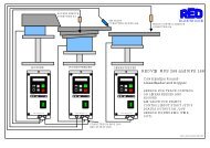
13.0 Connections for 3 A, 6 A, 8 A panel mounting versions<br />
Enable<br />
L, N, PE<br />
115 / 230V, 50/60Hz<br />
Material-Sensor<br />
- 4<br />
+<br />
5<br />
12...24V, DC<br />
Setpoint<br />
-<br />
+<br />
7<br />
8<br />
-<br />
+<br />
7<br />
8<br />
E<br />
10k<br />
External<br />
0(4)...20mA<br />
R=500 OHM<br />
0...10V<br />
external<br />
black<br />
Accelerometer<br />
Coil<br />
Recommended method of terminating<br />
screen of output cable<br />
Control unit<br />
Output cable<br />
SW...<br />
L<br />
N<br />
PE<br />
PE<br />
orange<br />
red<br />
E<br />
+24V<br />
S<br />
Screen *<br />
A<br />
+5V<br />
GND<br />
INPUT<br />
+ 24V<br />
internal<br />
relay<br />
1 2 3 4 5 6 7 8 9<br />
31 32 33 34<br />
21<br />
22 23 24 25 26 27 28 29<br />
SPEED<br />
The output cable to the feeder must be screened to conform with EMC regulations.<br />
F<br />
P<br />
REOVIB MFS 268<br />
ELEKTRONIK<br />
I<br />
0<br />
P P P<br />
When a potentiometer is connected parameter POT must be set to 1 in Menu C003..<br />
22
Operating Instructions REOVIB MFS 268 ELEKTRONIK<br />
13.1 Connections for 16 A panel mounting construction<br />
Material sensor<br />
Enable<br />
- 7<br />
Set point 0(4)...20mA<br />
-<br />
+<br />
7<br />
0...10V<br />
8<br />
+<br />
9<br />
Accelerometer<br />
- 4<br />
+<br />
5<br />
12...24V, DC<br />
SW...<br />
Feeder<br />
Spring-clamp for screen connection of output and<br />
accelerometer cables.<br />
L<br />
N<br />
PE<br />
PE<br />
E<br />
10k<br />
E<br />
+24V<br />
black<br />
S<br />
orange<br />
red<br />
PE<br />
A<br />
26 27 28 29 1 2 3 4 5 6 7 8 9 10<br />
31 32 33<br />
21<br />
22 23<br />
24 25 29<br />
+10V<br />
GND<br />
I<br />
+ 24V<br />
SPEED<br />
ELEKTRONIK<br />
P P P<br />
The output cable to the feeder must be screened to conform with EMC regulations.<br />
F<br />
P<br />
REOVIB MFS 268<br />
I<br />
0<br />
23
Operating Instructions REOVIB MFS 268<br />
14.0 Dimensions for 3 A, 6 A, 8 A Units<br />
Enclosed construction<br />
A<br />
F<br />
P<br />
5<br />
REOVIB MFS 268<br />
I<br />
0<br />
SPEED<br />
P P P<br />
I<br />
O<br />
ca. 2 m<br />
Panel mounting construction<br />
3A 6A 8A<br />
A 90 90 100<br />
B 140 186 204<br />
C 94 94 104<br />
D 132 175 195<br />
All dimensions in [mm]<br />
24<br />
1 2 3 4 5 6 7 8 9<br />
31 32 33 34<br />
21 22 23 24 25 26 27 28 29<br />
F<br />
P<br />
MFS 268<br />
I<br />
0<br />
SPEED<br />
P P P<br />
1 2 3 4 5 6 7 8 9<br />
31 32 33 34<br />
21 22 23 24 25 26 27 28 29<br />
5<br />
F<br />
P<br />
MFS 268<br />
I<br />
0<br />
SPEED<br />
P P P<br />
C D<br />
B<br />
12<br />
>10<br />
1 2 3 4 5 6 7 8 9<br />
31 32 33 34<br />
21 22 23 24 25 26 27 28 29<br />
ELEKTRONIK<br />
>100<br />
F<br />
P<br />
MFS 268<br />
>100<br />
I<br />
0<br />
SPEED<br />
P P P<br />
>10
Operating Instructions REOVIB MFS 268 ELEKTRONIK<br />
14.1 Dimensions of 12 A Unit<br />
150<br />
14.2 Dimensions of 16 A Unit<br />
26 27 28 29 1 2 3 4 5 6 7 8 9 10 31 32 33 21<br />
+10V<br />
GND<br />
E<br />
+ 24V<br />
22 23<br />
24 25 29<br />
104<br />
ELEKTRONIK<br />
F<br />
P<br />
5<br />
SPEED<br />
P P P<br />
REOVIB MFS 268<br />
I<br />
0<br />
300<br />
F<br />
P<br />
I<br />
0<br />
I<br />
O<br />
ca. 2 m<br />
205<br />
193<br />
210<br />
250<br />
203<br />
25
Operating Instructions REOVIB MFS 268<br />
A 1.0 Service appendix<br />
ELEKTRONIK<br />
ATTENTION !<br />
The settings described in this section relating to the service menu are intended for use by skilled<br />
persons because the functions and limits of the feed system can be greatly influenced by their<br />
adjustment<br />
It is the responsibility of the supplier of the equipment to decide whether this information should<br />
be released or restricted for use by service engineers only.<br />
The service menu cannot be accessed through the normal menu structure. It can only be enabled<br />
by using a special key code.<br />
A 1.1 Service Menu<br />
The critical parameters, current limit and user adjustable frequency range are held in a separate service<br />
menu. This menu cannot be reached through the normal menu structure and must be enabled by using<br />
an additional code number. This prevents the unauthorised changing of these sensitive parameters<br />
• Current Limit – Protects the coil against overload.<br />
The output current limit is set to the maximum current rating of the coil.<br />
• Frequency limits – Protection against unhealthy operation.<br />
The vibrating frequency limits available to the user are fixed.<br />
• Output voltage limit 100 V<br />
The output voltage limit allows 110v coils to be used on a 230V supply without damage.<br />
Parameter: Display Factory<br />
setting:<br />
Entry code:<br />
• Enable service menu 0 / I En.C: 0 127<br />
• Adjust current limit 0...100 % I. 100 040<br />
• Set lower frequency 5...300 Hz F.L. 35 040<br />
• Set upper frequency 6...300 Hz F.H. 140 040<br />
• Limit output voltage 100 V 0 / I P.Li. 0 040<br />
26
Operating Instructions REOVIB MFS 268 ELEKTRONIK<br />
A 1.2 Frequency adjustment range<br />
The control unit is supplied with a maximum frequency range of 5…150Hz. Using an adjustable under<br />
and over frequency limits, the user range (parameter F) can be restricted to a maximum ratio of 1:4.<br />
In regulation mode, this restricted frequency range has great importance because it assists with the accurate<br />
determination of the measurement signals from the accelerometer. During the automatic frequency<br />
search a maximum sweep range of 1:4 is possible. The lower (FL) and upper (FH) frequency limits restrict<br />
the range. A narrow setting of the limits of less than 1:4 is possible and also advisable because this<br />
ensures that widely different changes of the frequency cannot occur when the user is setting up the system.<br />
The range of the automatic frequency control (AFC) is also limited by these settings.<br />
A practical setting is +/- 20 % of resonance.<br />
Possible frequency range<br />
Parameter "F.L." and "F.H."<br />
Menü "C 040"<br />
Usable frequency range<br />
Parameter "F"<br />
Menü "C 008", "C 096", C "020"<br />
1. Set lower frequency limit.<br />
2. Set upper frequency limit.<br />
A 1.3 Current limiting<br />
F.L. F.H.<br />
5 Hz 300 Hz<br />
F.L.<br />
max. 1 : 4<br />
The current limit is used to set the controller for the rated current of the coil IM. The current limit IMAX is set<br />
by using parameter I. The displayed setting is expressed as a percentage of the controllers rated current<br />
IN (100 % corresponds to the units rated current).<br />
I<br />
MAX<br />
=<br />
I<br />
M<br />
⋅100<br />
I<br />
N<br />
To protect the coils the current limit must be set to the rated current for the coil(s) IM .<br />
When several coils are connected in parallel the coil current is the sum of all individual currents.<br />
F.H.<br />
27
Operating Instructions REOVIB MFS 268<br />
Enable Service Mode<br />
The actual service menu is accesed by opening the service mode.<br />
P P<br />
P<br />
P<br />
0 = Service mode off<br />
I = Service mode on<br />
Running mode<br />
ELEKTRONIK<br />
The normal service menu, containing the output current and frequency limit settings, is accessed by<br />
opening the service mode.<br />
Servicemenu<br />
Code 040<br />
P P<br />
F<br />
P<br />
P<br />
P<br />
P<br />
P<br />
P P<br />
P P<br />
P<br />
P<br />
P<br />
Actual current (display only)<br />
Current limit in % of I-max<br />
Lower frequency limit<br />
Upper frequency limit<br />
Only for units with push-pull output<br />
0 = DC , I = AC<br />
Output voltage limit<br />
100 V, 0 = off, I = on<br />
P P Actual frequency (display only)<br />
Running mode<br />
After making adjustments the service mode must be closed again!<br />
28
Operating Instructions REOVIB MFS 268 ELEKTRONIK<br />
A 2.0 Version in Stainless steel Enclosure<br />
440,00 mm<br />
380,00 mm<br />
Start / Stop Mainswitch<br />
Set point<br />
O<br />
OFF<br />
I ON<br />
29
Operating Instructions REOVIB MFS 268<br />
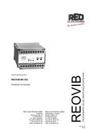
A 2.1 Connections for 15A panel in Stainless steel Enclosure<br />
Mainswitch<br />
30<br />
L1 N PE<br />
230 V 50/60 Hz<br />
16 A<br />
REOVIB MFS 268 XL<br />
Magnet 1 Magnet 2<br />
Set point<br />
10 KR<br />
26 27 28 7 8 10 21 22 23<br />
L1 N<br />
Frequency controller for vibratory feeders<br />
A1 A2<br />
PE<br />
PE<br />
GND<br />
24 25 29 4 5 6<br />
Stand-by<br />
E +10V<br />
GND E<br />
+24V<br />
X 1 24 24 PE X 1 25 25 PE X 1 4 5 6 X 1<br />
external contact<br />
or link<br />
GND<br />
black<br />
X 1 21 22 23<br />
31 32 33<br />
31 32 33<br />
orange<br />
E<br />
+24V<br />
rot<br />
Vibrator Sensor<br />
ELEKTRONIK<br />
(brown not connected)