Prehardened cold work tool steel for car body dies - Uddeholm
Prehardened cold work tool steel for car body dies - Uddeholm
Prehardened cold work tool steel for car body dies - Uddeholm

Create successful ePaper yourself
Turn your PDF publications into a flip-book with our unique Google optimized e-Paper software.
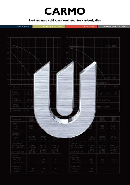
CARMO<br />
<strong>Prehardened</strong> <strong>cold</strong> <strong>work</strong> <strong>tool</strong> <strong>steel</strong> <strong>for</strong> <strong>car</strong> <strong>body</strong> <strong>dies</strong>
2<br />
CARMO<br />
This in<strong>for</strong>mation is based on our present state of knowledge and is<br />
intended to provide general notes on our products and their uses.<br />
It should not there<strong>for</strong>e be construed as a warranty of specific<br />
properties of the products described or a warranty <strong>for</strong> fitness <strong>for</strong> a<br />
particular purpose.
General<br />
CARMO is a high-strength, flame-, induction- and<br />
through hardening <strong>steel</strong> delivered prehardend to<br />
240–270 HB.<br />
The surface of the <strong>steel</strong> can be flame-hardened<br />
without water cooling to a hardness of 58 ±2 HRC.<br />
The depth of hardness is normally 4–5 mm and the<br />
hardened and tempered matrix is a good base <strong>for</strong><br />
the flame-hardened layer.<br />
The <strong>steel</strong> can be easily repair welded.<br />
Typical C Si Mn Cr Mo V<br />
analysis %<br />
Delivery<br />
0,6 0,35 0,8 4,5 0,5 0,2<br />
condition <strong>Prehardened</strong> to 240–270 HB<br />
Colour code Red/violet<br />
Applications<br />
CARMO is a <strong>cold</strong> <strong>work</strong> <strong>tool</strong> <strong>steel</strong> which has been<br />
developed together with the automotive industry.<br />
Its analysis has been balanced to give one universal<br />
<strong>tool</strong> <strong>steel</strong> <strong>for</strong> <strong>car</strong> <strong>body</strong> <strong>dies</strong> instead of the several<br />
<strong>steel</strong> grades (flame hardening and through<br />
hardening grades) which are normally used.<br />
The <strong>steel</strong> can be used in the flame-hardened or in<br />
the through-hardened condition <strong>for</strong> blanking and<br />
<strong>for</strong>ming of both <strong>car</strong> <strong>body</strong> parts (thin sheet) or<br />
structural parts (thicker sheet).<br />
Properties<br />
MECHANICAL PROPERTIES<br />
Typical values at room temperature, 270 HB.<br />
Tensile strength<br />
Rm<br />
N/mm2 870<br />
Yield point<br />
Rp0,2<br />
N/mm2 670<br />
Elongation A5 % 15<br />
Reduction of area Z % 50<br />
CARMO<br />
OTHER IMPORTANT PROPERTIES<br />
Total <strong>tool</strong>ing economy, i.e. minimizing the total<br />
cost incurred in running the <strong>tool</strong>—including downtime<br />
and maintenance—is important in press<strong>work</strong><br />
operations. It is of particular importance in the<br />
automotive industry where very large, automated<br />
press-lines are operating to a just-in-time concept.<br />
This puts very special requirements on the <strong>steel</strong>s<br />
used <strong>for</strong> the <strong>tool</strong>ing:<br />
• high toughness <strong>for</strong> maximum safety in operation<br />
• high wear resistance to achieve the number of<br />
parts required<br />
• easy maintenance to minimize press downtime.<br />
These requirements are fully met by CARMO.<br />
The toughness of CARMO is much better than <strong>for</strong><br />
the <strong>steel</strong> types A2 and D2.<br />
The wear resistance of CARMO is very similar to<br />
that of A2.<br />
Repair welding of CARMO is easy.<br />
3
4<br />
CARMO<br />
Heat-treatment<br />
STRESS RELIEVING<br />
Temperature: 550–650°C (1020–1200°F).<br />
Holding time: 2h. Cooling in furnace to 500°C<br />
(930°F), then in air.<br />
HARDENING<br />
For through hardening following temperatures<br />
and times are recommended:<br />
Pre-heating temperature: 600–700°C (1110–<br />
1290°F).<br />
Austenitizing temperature: 950–970°C (1740–<br />
1780°F), normally 960°C (1760°F).<br />
Holding time: 30–45 minutes.<br />
The <strong>tool</strong> should be protected against de<strong>car</strong>burization<br />
during hardening.<br />
Hardness as a function of austenitizing temperature<br />
Hardness HRC<br />
64<br />
62<br />
60<br />
58<br />
123456789012345678<br />
123456789012345678<br />
123456789012345678<br />
123456789012345678<br />
123456789012345678<br />
123456789012345678<br />
123456789012345678<br />
123456789012345678<br />
123456789012345678<br />
123456789012345678<br />
123456789012345678<br />
123456789012345678<br />
123456789012345678<br />
123456789012345678<br />
900 925 950 975 1000 1025<br />
Austenitizing temperature °C<br />
123<br />
123<br />
123456789012345678<br />
123 Risk <strong>for</strong> grain growth and reduced toughness.<br />
QUENCHING<br />
• High speed gas/circulating atmosphere<br />
• Saltbath 200–550°C (390–1020°F)<br />
• Fluidized bed 200–550°C (390–1020°F).<br />
Note 1: Quenching should not be interrupted until<br />
the part has cooled down to 25°C (75°F).<br />
Otherwise the part may shrink after<br />
tempering.<br />
Note 2: Temper immediately after quenching.<br />
Note 3: Quenching in oil is not recommended.<br />
Core hardness as a function of diameter <strong>for</strong> air<br />
cooling.<br />
Core hardness HRC<br />
66<br />
62<br />
58<br />
54<br />
50<br />
1 5 10 20 40 100 200 400<br />
Diameter, mm<br />
TEMPERING<br />
The tempering temperature <strong>for</strong> the required<br />
hardness may be determined by means of the tempering<br />
graph. Temper twice. Lowest tempering<br />
temperature 200°C (390°F). Holding time at temperature<br />
minimum 2 hours.<br />
Hardness HRC<br />
65<br />
60<br />
55<br />
50<br />
45<br />
40<br />
SURFACE HARDNESS AFTER TEMPERING<br />
Tempering graph<br />
Retained austenite<br />
Retained austenite, %<br />
50<br />
T A = 960°C (1760°F)<br />
0 100 200 300 400 500 600<br />
Tempering temperature °C (2h + 2h)<br />
IMPACT STRENGTH<br />
Room temperature. Specimen size: 7 x 10 x 55 mm<br />
unnotched. Hardened at 960°C (1760°F).<br />
Quenched in air. Tempered twice.<br />
Impact energy Joule<br />
300<br />
250<br />
200<br />
150<br />
100<br />
50<br />
Impact strength<br />
Hardness<br />
0<br />
35<br />
200 250 300 350 400 450 500 550 600<br />
Tempering temperature °C (2h + 2h)<br />
40<br />
30<br />
20<br />
10<br />
Hardness HRC<br />
60<br />
55<br />
50<br />
45<br />
40
Machining<br />
recommendations<br />
The machining data provided below are intended<br />
as a guideline to help find the optimal conditions.<br />
The data were obtained from tests made in the<br />
prehardened condition. More detailed in<strong>for</strong>mation<br />
can be found in <strong>Uddeholm</strong> “Cutting Data Recommendations”.<br />
TURNING<br />
Turning with Turning with<br />
<strong>car</strong>bide high speed<br />
Cutting data Rough Fine <strong>steel</strong><br />
parameters<br />
Cutting speed<br />
turning turning Fine turning<br />
(vC) m/min 130–160 160–210 25<br />
f.p.m.<br />
Feed (f)<br />
430–530 530–690 60<br />
mm/r 0,3–0,6 –0,3 –0,3<br />
i.p.r. 0,012–0,023 –0,012 –0,012<br />
Depth of cut (ap) mm 2–6 –2 –2<br />
inch<br />
Carbide<br />
0,08–0,23 –0,08 –0,08<br />
designation ISO P20–P30 P10 –<br />
Coated Coated<br />
<strong>car</strong>bide <strong>car</strong>bide or<br />
cermet<br />
MILLING<br />
Face and square shoulder milling<br />
Milling with Milling with<br />
<strong>car</strong>bide high speed<br />
Cutting data Rough Fine <strong>steel</strong><br />
parameters<br />
Cutting speed<br />
milling milling Fine milling<br />
(vC) m/min 110–140 140–180 18<br />
f.p.m. 360–460 460–590 60<br />
Feed (fZ) mm/tooth 0,2–0,4 0,1–0,2 0,1<br />
inch/tooth<br />
Depth of cut<br />
0,008–0,016 0,004–0,008 0,004<br />
(a ) P<br />
mm 2–5 –2 –2<br />
inch<br />
Carbide<br />
designation<br />
0,08–0,20 0,08 0,08<br />
ISO P20–P40 P10–P20 –<br />
Coated Coated<br />
<strong>car</strong>bide <strong>car</strong>bide or<br />
cermet<br />
End milling<br />
CARMO<br />
Cutting data Solid<br />
Type of end mill<br />
Carbide<br />
indexable High speed<br />
parameters<br />
Cutting<br />
<strong>car</strong>bide insert <strong>steel</strong><br />
speed (vC) m/min 50 120–170 201) f.p.m. 165 395–560 651) Feed (f Z)<br />
mm/tooth 0,03–0,20 2) 0,08–0,20 2) 0,05–0,35 2)<br />
inch/tooth 0,001–0,008 2) 0,003–0,008 2) 0,002–0,014 2)<br />
Carbide<br />
designation<br />
ISO K20 P20–P40<br />
Coated <strong>car</strong>bide<br />
1) For coated HSS end mill vC ~28 m/min. (90 f.p.m.).<br />
2) Depending on radial depth of cut and cutter diameter.<br />
DRILLING<br />
High speed <strong>steel</strong> twist drill<br />
Drill diameter Cutting speed (vc) Feed (f)<br />
mm inch m/min f.p.m. mm/r i.p.r.<br />
–5 –3/16 14* 46* 0,08–0,20 0,003–0,008<br />
5–10 3/16–3/8 14* 46* 0,20–0,30 0,008–0,012<br />
10–15 3/8–5/8 14* 46* 0,30–0,35 0,012–0,014<br />
15–20 5/8–3/4 14* 46* 0,35–0,42 0,014–0,016<br />
* For coated HSS drills v C ~18 m/min. (60 f.p.m.).<br />
Carbide drill<br />
Type of drill<br />
Cutting data Indexable Solid Brazed<br />
parameters insert <strong>car</strong>bide <strong>car</strong>bide1) Cutting<br />
speed(vC) m/min 150–200 70 60<br />
f.p.m.<br />
Feed (f)<br />
500–660 230 200<br />
mm/r 0,03–0,10 0,10–0,252) 0,15–0,252) i.p.r. 0,001–0,004 0,004–0,012) 0,006–0,012) 1) Drills with internal cooling channels and a brazed<br />
<strong>car</strong>bide tip.<br />
2) Depending on drill diameter.<br />
GRINDING<br />
A general grinding wheel recommendation is<br />
given below. More in<strong>for</strong>mation can be found in the<br />
<strong>Uddeholm</strong> brochure “Grinding of Tool Steel”.<br />
Wheel recommendation<br />
Type of grinding <strong>Prehardened</strong> condition<br />
Surface grinding<br />
straight wheel A 46 HV<br />
Surface grinding segments A 24 GV<br />
Cylindrical grinding A 46 LV<br />
Internal grinding A 46 JV<br />
Profile grinding A 100 LV<br />
5
6<br />
CARMO<br />
Flame-hardening<br />
Use an oxy-acetylene burner <strong>for</strong> 1250–2500 l/h<br />
with a normal flame.<br />
Temperature: 950 ±30°C (1740 ±50°F).<br />
Hardness: surface 58 ±2 HRC, at a depth of 3–4 mm<br />
400 HV 10 kg .<br />
A temperature guide <strong>for</strong> judgement of the right<br />
flame hardening temperature can be obtained from<br />
your local <strong>Uddeholm</strong> office.<br />
Welding<br />
recommendations<br />
GENERAL<br />
When <strong>cold</strong> <strong>work</strong> <strong>steel</strong>s are welded, there is always<br />
a risk of cracking in the weld metal and/or in the<br />
heat affected zone (HAZ). However, cracking can<br />
be avoided by using a proper welding technique<br />
and the right consumables. Wrought material is<br />
always easier to weld than castings because it has a<br />
higher toughness.<br />
In general, the following is valid:<br />
• Always keep the arc length as short as possible.<br />
The coated electrode should be angled at 90° to<br />
the joint sides to avoid undercut. In addition, the<br />
electrode should be held at an angle of 75–80°<br />
to the direction of <strong>for</strong>ward travel.<br />
• Larger repair welds must be made at elevated<br />
temperature. The temperature of the <strong>work</strong>piece<br />
should be held as constant as possible during<br />
welding. The best way to keep the <strong>tool</strong> at constant<br />
temperature during welding is to use an<br />
insulated box with thermostatically regulated<br />
electrical heating elements inside the walls.<br />
• The first two layers should always be welded<br />
with the same heat input and with a small diameter<br />
electrode (max 3,25 Ø electrode <strong>for</strong><br />
MMA or max 120A <strong>for</strong> TIG welding).<br />
• First of all, the parent metal is clad in using an<br />
appropriate number of runs. All other runs<br />
should then be made up on top of pre-existing<br />
weld metal except in those cases where soft<br />
metal electrodes of the type 29/9 are used.<br />
When a soft weld metal is used, a space of<br />
3 mm must be left below the finished surface so<br />
that the hard facing electrode can be used to<br />
give the right surface hardness on the welded<br />
<strong>tool</strong>.<br />
• For large weld repairs, the parent metal should<br />
be coated with a soft weld metal of the 29/9 type<br />
(i.e. 29% Cr, 9% Ni electrodes AWS ER 312 or<br />
AWS E312), which gives a tougher weld metal<br />
with lower hardness.<br />
• The choice of electrode <strong>for</strong> welding depends on<br />
the hardness required in the weld metal (see<br />
table below).<br />
• In order to obtain the required hardness (as<br />
given in the table below), the weld should be<br />
built up with at least 3 layers plus an additional<br />
layer which is ground off after welding has been<br />
completed. When welding <strong>tool</strong> <strong>steel</strong>s, the last<br />
layer should always be ground off.<br />
• It should be noted that differences between expected<br />
and achieved hardness in the weld metal<br />
normally depend on how the grinding of the last<br />
layer has been <strong>car</strong>ried out. Grinding should<br />
always be <strong>car</strong>ried out be<strong>for</strong>e the temperature in<br />
the <strong>tool</strong> sinks too much. If the grinding is too<br />
rough so that the weld becomes red hot, microcracks<br />
will appear in the weld metal.<br />
• The following heat treatment cycle is recommended<br />
<strong>for</strong> large weld repairs:<br />
1. Pre-heat the <strong>tool</strong> to 200–250°C (390–480°F).<br />
Keep that temperature during the whole<br />
welding operation.<br />
2. Let the <strong>tool</strong> cool slowly after welding to 70°C<br />
(160°F).<br />
3. Temper the <strong>tool</strong> at a temperature 20°C<br />
(70°F) below previously used preheating<br />
temperature.<br />
JOINT PREPARATION<br />
The importance of <strong>car</strong>eful joint preparation cannot<br />
be over-emphasized. Cracks should be ground out<br />
so that the joint bottom is rounded and the sides of<br />
the joint slope at an angle of at least 30° to the<br />
vertical. The width of the joint bottom should be at<br />
least 1 mm greater than the electrode diameter<br />
(including the coating) which is used.<br />
Further recommendations on welding of <strong>tool</strong> <strong>steel</strong>s<br />
can be found in the <strong>Uddeholm</strong> brochure “Welding<br />
of Tool Steel”.<br />
TIG Welding Consumables <strong>for</strong> wrought CARMO<br />
Hardness<br />
Condition Hardness after re- Preheating 1)<br />
of material Consumables as welded hardening temperature<br />
Hardened Avesta P7 2) 240 HB Austenitic<br />
Pre- CastoTig 680 2) 230 HB Austenitic<br />
hardened UTPA 73G2 53–56 HRC 57 HRC<br />
UTPA 67S 55–58 HRC 52 HRC<br />
CastoTig 5 3) 60–64 HRC<br />
CARMO/<br />
CALMAX<br />
TIG WELD 4) 58–61 HRC 58–61 HRC<br />
200–250°C<br />
(390–480°F)
MMA (SMAW) Consumables <strong>for</strong> wrought CARMO<br />
Condition Hardness<br />
of Hardness after re- Preheating1) Condition<br />
of material Consumables as welded hardening temperature<br />
Hardened Avesta P7 5) ca 270 HB Austenitic<br />
Pre- Castolin 680S 5) ca 220 HB Austenitic<br />
hardened Sandvik<br />
29.9.R 5) ca 250 HB Austenitic<br />
ESAB OK 84.52 53–54 HRC 49 HRC<br />
UTP 67S 55–58 HRC 52 HRC<br />
Oerlikon<br />
CITODUR 600B 57–60 HRC 53–54 HRC<br />
Fontargen E 711 57–60 HRC 53–54 HRC<br />
CARMO/CAL-<br />
MAX WELD 4) 58–61 HRC 58–61 HRC<br />
200–250°C<br />
(390–480°F)<br />
Remarks:<br />
1) The <strong>tool</strong> should cool slowly after welding.<br />
2) TIG rods of the type AWS ER 312.<br />
3) CastoTig 5 should not be used <strong>for</strong> more than 4 layers<br />
because of the risk of cracking in the weld.<br />
4) CARMO/CALMAX TIG WELD/WELD consumables<br />
corresponds to the chemical composition of<br />
CARMO/CALMAX, i.e. similar heat treatment respons.<br />
5) MMA-Consumables of the type AWS E 312.<br />
Cold <strong>work</strong><br />
applications<br />
TYPICAL APPLICATION AREAS<br />
• General blanking and <strong>for</strong>ming<br />
• Heavy duty blanking and <strong>for</strong>ming<br />
• Deep drawing<br />
• Coining<br />
• Cold extrusion <strong>dies</strong> with complicated geometry<br />
• Rolls<br />
• Shear blades<br />
• Prototype <strong>tool</strong>ing.<br />
TRADITIONAL PRESSWORK STEELS<br />
The majority of press<strong>work</strong> <strong>tool</strong>s used today are<br />
manufactured using traditional <strong>tool</strong> <strong>steel</strong>s such as<br />
O1, A2, D2, D3 and D6.<br />
These <strong>steel</strong>s offer an apparent adequate wear resistance<br />
and their hardness range is suitable <strong>for</strong><br />
most applications. However, the poor toughness,<br />
flame- and induction hardenability and weldability<br />
of these grades often results in low productivity<br />
and high maintenance costs due to unexpected<br />
<strong>tool</strong> failure. For this reason, the new general press<strong>work</strong><br />
<strong>tool</strong> <strong>steel</strong> CARMO has been developed. The<br />
aim of CARMO is to secure an optimal <strong>tool</strong>ing<br />
economy, i.e. the lowest <strong>tool</strong>ing costs per part produced.<br />
TODAYS DEMANDS<br />
The press<strong>work</strong> industry has gone through some<br />
considerable changes in the last decades. Stainless<br />
<strong>steel</strong> and surface coated strip have been commer-<br />
CARMO<br />
cialized and high speed presses have been developed.<br />
To these technological advances just in time<br />
(JIT) manufacture and the moves toward increased<br />
productivity and <strong>tool</strong> life guarantees must be<br />
added. The traditional press<strong>work</strong> <strong>tool</strong> <strong>steel</strong>s are<br />
still routinely specified and selected but often result<br />
in poor <strong>tool</strong> per<strong>for</strong>mance and productivity.<br />
The well balanced properties profile of CARMO is<br />
much better matched to modern <strong>work</strong> materials<br />
and manufacturing methods. CARMO offers the<br />
high degree of safety which is essential <strong>for</strong> optimal<br />
<strong>tool</strong>ing per<strong>for</strong>mance and maximum productivity.<br />
RESISTANCE TO FAILURE MECHANISMS<br />
<strong>Uddeholm</strong> Abrasive Adhesive Chipping/ De<strong>for</strong>grade<br />
wear wear Cracking mation<br />
CALMAX/<br />
CARMO*<br />
ARNE<br />
SVERKER 21<br />
SVERKER 3<br />
RIGOR<br />
* CARMO is delivered in prehardened condition in order to<br />
improve the flame-/induction hardenability, which is the<br />
normal hardening procedure <strong>for</strong> CARMO. But CARMO<br />
can however also be through hardened. All other <strong>steel</strong>s<br />
in this table are normally through hardened.<br />
Further in<strong>for</strong>mation<br />
Please contact your local <strong>Uddeholm</strong> office <strong>for</strong> further<br />
in<strong>for</strong>mation on the selection, heat treatment<br />
and application of <strong>Uddeholm</strong> <strong>tool</strong> <strong>steel</strong>s.<br />
Tool <strong>for</strong> producing floor parts.<br />
7