P-I Servoamplifier G122-824-002 - Fluidtech
P-I Servoamplifier G122-824-002 - Fluidtech
P-I Servoamplifier G122-824-002 - Fluidtech
- No tags were found...
Create successful ePaper yourself
Turn your PDF publications into a flip-book with our unique Google optimized e-Paper software.
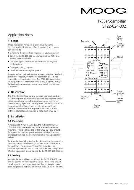
P-I <strong>Servoamplifier</strong><strong>G122</strong>-<strong>824</strong>-<strong>002</strong>Application Notes1 ScopeThese Application Notes are a guide to applying the<strong>G122</strong>-<strong>824</strong>-<strong>002</strong> P-I <strong>Servoamplifier</strong>. These Application Notescan be used to: Determine the closed loop structure for your application. Select the <strong>G122</strong>-<strong>824</strong>-<strong>002</strong> for your application. Refer alsoto data sheet <strong>G122</strong>-<strong>824</strong>. Use these Application Notes to determine your systemconfiguration. Draw your wiring diagram. Install and commission your system.Aspects, such as hydraulic design, actuator selection, feedbacktransducer selection, performance estimation etc. are notcovered by this application note. The <strong>G122</strong>-202 ApplicationNotes (part no C31015) cover some of these aspects. MoogApplication Engineers can provide more detailed assistance,if required.2 DescriptionThe <strong>G122</strong>-<strong>824</strong>-<strong>002</strong> is a general purpose, user configurable,P-I servoamplifier. Selector switches inside the amplifier enableeither proportional control, integral control, or both to beselected. Many aspects of the amplifier’s characteristics can beadjusted with front panel pots or selected with internalswitches. This enables one amplifier to be used in manydifferent applications. Refer also to data sheet <strong>G122</strong>-<strong>824</strong>.3 Installation3.1 PlacementA horizontal DIN rail, mounted on the vertical rear surfaceof an industrial steel enclosure, is the intended method ofmounting. The rail release clip of the <strong>G122</strong>-<strong>824</strong>-<strong>002</strong> shouldface down, so the front panel and terminal identificationsare readable and so the internal electronics receive a coolingairflow.An important consideration for the placement of the module iselectro magnetic interference (EMI) from other equipment inthe enclosure. For instance, VF and AC servo drives canproduce high levels of EMI. Always check the EMC complianceof other equipment before placing the <strong>G122</strong>-<strong>824</strong>-<strong>002</strong> close by.3.2 CoolingVents in the top and bottom sides of the <strong>G122</strong>-<strong>824</strong>-<strong>002</strong> caseprovide cooling for the electronics inside. These vents shouldbe left clear. It is important to ensure that equipment belowdoes not produce hot exhaust air that heats up the <strong>G122</strong>-<strong>824</strong>.Top vents2517BottomventsVs26182719feedbackgainzero28201 2 3 49 10 11 122921MOOGditherin posn.3022valveinp.1CoolingairflowPI3123enablescalegaingainbiascontroller32245 6 7 813 14 15 16Coverreleasetab (4)Screwterminals17 - 32DIN railScrewterminals1 - 16DIN railreleaseclipPage 1 of 6: C31881 Rev F 01.06
3.3 WiringThe use of crimp “boot lace ferrules” is recommended for thescrew terminals. Allow sufficient cable length so the circuitcard can be withdrawn from its case with the wires stillconnected. This enables switch changes on the circuit cardto be made while the card is still connected and operating.An extra 100mm, for cables going outside the enclosure,as well as wires connecting to adjacent DIN rail units,is adequate.5 Set-up adjustmentsThe screw terminals will accommodate wire sizes from 0.2mm 2to 2.5mm 2 (24AWG to 12AWG). One Amp rated, 0.2mm 2should be adequate for all applications.EnclosureGrounded EMIcable glandCableWires100mm LoopTo access the circuit card switches, the circuit card must bewithdrawn from the case. See paragraph 17.Switch positionsRadial screenterminationPreferred WiringONshown in on positionshown in off positionEnclosureCable glandCable3.4 EMCWire solderedto screenorDrain wire.(Heat shrink tocover the screen)Alternative WiringCable100mm LoopThe <strong>G122</strong>-<strong>824</strong>-<strong>002</strong> emits radiation well below the level calledfor in its CE mark test. Therefore, no special precautions arerequired for suppression of emissions. However, immunity fromexternal interfering radiation is dependent on careful wiringtechniques. The accepted method is to use screened cables forall connections and to radially terminate the cable screens, inan appropriate grounded cable gland, at the point of entry intothe industrial steel enclosure. If this is not possible, chassisground screw terminals are provided on the <strong>G122</strong>-<strong>824</strong>-<strong>002</strong>.Exposed wires should be kept to a minimum length. Connectthe screens at both ends of the cable to chassis ground.4 Power supply24V DC nominal, 22 to 28V75mA @ 24V without a load, 200mA @ 100mA load.If an unregulated supply is used the bottom of the ripplewaveform is not to fall below 22V.It is recommended that an M205, 250mA T (slow blow) fuse,compliant to IEC127-2 sheet 3, be placed in series with the+24V input to protect the electronic circuit.Trimpots are all 15 turns.Plug-in resistors are all “quarter watt” 1% metal film. Twosuitable types are Beyschlag MBB0207 and RodersteinMK20207.The amplifier is shipped in the following default state. top board switchesSW 11 I lim off2 INT off3 PROP on4 5mA off5 10mA off6 20mA off7 30mA off8 50mA onSW 31 4-20mA off2 ±10V on3 4-20mA off4 4-20mA offSW 21 CMD LAG off2 Iin = E on3 Iin = P off4 V off5 V off6 V off7 I on8 I on bottom board switchesSW 11 spare off2 ENABLE on3 DITHER off4 4-20mA onPage 2 of 6: C31881 Rev F 01.06
R17: 100k (P gain range 1 to 20) R34: 100k (input 2 to error amp) R33: not fitted (input 2 to output amp) R16: not fitted (feedback derivative) Feedback gain and zero pots: configured for 4-20mA input Dither level pot: fully counter clockwise (FCCW) Scale pot: FCCW P gain pot: FCCW I gain pot: FCW (prior to S.N. M1084, was FCCW)Note that FCW is min. I gain = longest integrator time. Bias pot: 0VCautionIf you intend to use the feedback amplifier adjusted for4-20mA, don’t change the feedback gain or zero. They are already adjusted for 4-20mA To re-adjust for 4-20mA takes a little time, needs testequipment and is tedious to do in the field.6 Input configurationAll three inputs can be used for feedback or command.Care needs to be taken in selecting signal polarity to achievenegative feedback for the overall closed loop. Since the inputerror amplifier sums the signals, the transducer feedback signalneeds to be the opposite polarity of the command. This can beachieved in two ways: Arrange for an opposite polarity feedback transducer signaland connect it to input 1, input 2 or the positive feedbackamplifier input. If the feedback transducer signal is the same polarity as thecommand, you only have one option: Connect it to thenegative input of the feedback amplifier.6.1 Feedback inputThe feedback amplifier is the best choice for the feedbacksignal, for five reasons: It leaves input 1 available for command. See 6.2 below. It has inverting (negative) and non-inverting (positive) inputs. It has zero and gain adjustment pots. This enables a signalthat does not go to zero volts and has less span than thecommand, to be scaled up to the command. While this isnot essential, it helps when setting up and trouble-shooting. There is a front panel test point for the zeroed and amplifiedsignal. This is very convenient (essential) for setting up andtrouble-shooting. There is the option of a plug-in resistor, R16, to give afeedback derivative (lead or D) in the output of the feedbackamplifier.DefaultThe feedback amplifier default set-up is 4-20mA flowing intoterminal 18 and out of terminal 17, producing an output of0 to -10V. Reversing the terminals, and hence the current flow,will not result in a 0 to +10V output. The feedback gain andzero must be adjusted for this arrangement.6.2 Input 1This input is ±10V non-inverting and has two importantfeatures: It has a scale pot on its input that enables large inputs to bescaled down to match smaller signals on other inputs. Scalerange is 10 to 100%. Set fully clockwise (FCW), an input of100V can match a 10V signal on the other inputs. It has a switch selectable lag of 55mS that can be used toremove transients from the input signal that could causeunwanted rapid movement in the output.Input 1 is well suited to be a command because of these twofeatures. If input 1 is used for feedback, be sure the lag isswitched off. Input resistance after the scale pot is 94k Ohms.6.3 Input 2This input is non-inverting. It is switch selectable between4-20mA and ±10V. The 4-20mA converter produces 0 to +10Vfor 4 to 20mA input. R34 connects from the output of theconverter to the input of the servo amp when 4-20mA isselected. Plug-in input resistor R34, of 100k Ohms, gives anominal 0 to 10V input signal range when V rather than4-20mA is selected. Input 2 is suitable for command orfeedback. R34 can be increased to give a larger input range.7 Output configurationSelect the output to match the input requirements of the valve.When voltage (V) is selected, ±10V is available into a minimumload of 200 Ohm. When current (I) is selected, the current levelswitches enable ±5 to ±100mA to be selected. The switchselections sum, so, if for instance 45mA is required, select30,10 and 5. The output can drive all known Moog valves upto ±100mA. The maximum load at I (Amp) output is:( )RL max =11V– 39 OhmI (Amp)eg. at 50mA RL max is 181 OhmThe output amplifier is limited to approximately 105% of theselected full scale output. If both the proportional andintegrator stages are saturated, the output will not be twicethe selected full scale but still only 105% of full scale.8 Step push buttonThe step push button injects -50% valve drive disturbanceinto the output. When released, the valve drive reverts to itsoriginal level. This feature is useful for closed loop gainoptimisation.9 P-I selectionFor position closed loops, initially select only P. For pressure orvelocity loops select I initially and then P. See paragraph 12below for more detail. For a complete discussion of P and Icontrol, see the <strong>G122</strong>-202 servoamplifier Application Notes(part no C31015).10 Integrator inputThe servoamplifier has a unity gain input error amplifierfollowed by two parallel stages, one a proportional amplifierand the other an integrator. The outputs of these two stagescan be switched to the output power amplifier (see paragraph7 above) which then drives the valve.The input to the integrator stage can be switch selected fromeither the output of the error amplifier, I in = E, or the outputof the proportional stage, I in = P. The latter arrangement isused in the <strong>G122</strong>-202. It is beyond the scope of theseApplication Notes to detail the benefits of each arrangement.If you have experience with the <strong>G122</strong>-202, I in = P wouldseem to be an easy choice.Page 3 of 6: C31881 Rev F 01.06
11 P only gainFor position loops select only P control. Input a stepdisturbance of 50% valve current with the step push button.Adjust the P gain for the required stability, while monitoringthe front panel valve test point, or the feedback signal. Thegain range of the proportional amplifier can be moved bychanging the plug-in resistor R17. The value loaded whenshipped is 100k Ohms, which gives a 1 to 20 range. Selecting200k Ohms will give 2 to 40. The circuit will function correctlywith the value of R17 between 100k Ohms and 10M Ohms.Note that as P gain is increased, the movement due to the steppush button decreases.12 P and I gains togetherIf you are inexperienced with integral control the followingset-up method is a good starting point. I in = E: Initially select only I. Press the step push button.Increase I gain until one overshoot in the feedback signalis observed.Next select P and I together and increase the P gain to reducethe overshoot.For the I in = E arrangement the P and I sequence could bereversed. i.e.: adjust P first, followed by I. I in = P: For an I in = P arrangement, only the “P followedby I” sequence of adjustment can be used.For a more thorough discussion see <strong>G122</strong>-202 ApplicationNotes (part no C31015).16 In positionWhen the valve drive signal falls below ±10% of the selectedfull scale signal, the “in position” signal goes true and providesan opto-isolated current path between the + and – terminals.This can be connected to a PLC to initiate the next step in acontrol sequence. Do not apply more than 40V to the +terminal and ensure the load on the – terminal is less than20mA.The “in position” signal is not relevant for a velocity loop.17 Withdrawing the circuit cardfrom its caseThe circuit card needs to be withdrawn from its case to set theselector switches and operate the step push button.To do this, push one tab (item 4) with a pen or screwdriver,while gently pulling on the top cover on that side. The coverwill release approximately one mm. Repeat on the second tabon that side. Repeat on the other side and then withdraw thecover and circuit card until the required switches are exposed.The rigidity of the connecting wires will hold the circuit cardin position while the switches are set.13 I limitThe contribution from the integrator to the output amplifiercan be reduced by selecting I limit on. When this switch is onthe integrator contribution is reduced to approximately 15% ofthe level when it is off. This feature is useful in a position loopthat may require integral control to achieve the required steadystate accuracy. The limited integral control removes valve nullerror when the final position is reached. It is also useful in apressure loop to limit overshoot, if the valve drive saturates.14 DitherThe dither frequency is fixed at 200Hz and the level isadjustable with the front panel pot to ±10% of valve drive,regardless of the type and level of valve drive selected. Ditheris seldom needed in a position loop but can be beneficial inpressure or velocity loops. Increase dither until it can just bedetected in the controlled variable, such as pressure or velocity.Dither can compromise valve life, so it should be kept toa minimum.15 EnableA relay on the circuit card needs to be energised to connectthe output stage to its screw terminal and to un-clamp theintegrator. The clamp prevents integrator wind-up when theloop is not operating. Supply 24V to the appropriate terminalto energise the relay. The enable switch on the circuit card canbe set to permanently energise the relay and provide apermanent enable.Page 4 of 6: C31881 Rev F 01.06
18 SpecificationsFunction:P, I, or P & I, switch selectableInput 1:Scaled to 95V max with switchselectable lag of 55mS.Input 2: 4-20mA 240R load, for 0 to +10V on R34.Or 0 to ±10V direct onto R34.R34 is plug-in, 100K nominal.Feedback input: Differential 4-20mA or ±10V, switchselectable±15V max.R in 100k – ±10VR in 240R – 4-20mAFeedback amp: Zero, ±10V.Gain, 1 to 10.Derivative (velocity) feedback viaplug-in resistor and fixed capacitor.Transducer excitation: +10V @ 10mA max.Error amp:Unity gain.Bias ±1.5V.Proportional amp gain: 1 to 20.Integrator gain: 1 to 45 per second.Integrator input: Switch selectable from output of unitygain error amp or proportional gain ampEnable: Relay, +24V @ 8mA, 17 to 32V.Output amp:Switch selectable voltage or current, singleended output, return to ground.V. ±10V, minimum load = 200 OhmI. ±5, 10, 20, 30, 50mA to a maximumof ±100mAmax load =11V– 39 Ohm( I (Amp) )Step push button: -50% valve drive disturbance.Valve supply:Pin 14, 300mA max.In position:±10% of valve drive. 20mA and 40V maxoutput to PLC.Front panelindicators:Front paneltest points:Vs, internal supply – greenValve drive positive – rednegative – greenEnable – yellowIn position – greenValve ±10V (regardless of outputsignal selection)Feedback amplifier outputsignal 0VInput 1 scaleError amp biasFront paneltrimpots:(15 turns) P gainI gainDither levelFeedback amp gainFeedback amp zeroDither:200 Hz fixed frequency.±10% valve drive. Switch selectable on/offSupply:24V nominal, 22 to 28V75mA @ 24V, no load,200mA @ 100mA loadWire size range: 0.2mm 2 to 2.5mm 2(24AWG to 12AWG)Recommended M205, 250mA T (slow blow) fusesupply protection: compliant to IEC127-2 sheet 3Mounting:DIN railIP 20Temperature:0 to +40ºCDimensions:100W x 108H x 45DWeight:180gCE mark:EN50081.1 emissionEN61000-6-2 immunityC tick:AS4251.1 emission19 Internetwww.moog.com/dinmodulesPage 5 of 6: C31881 Rev F 01.06
20 Block-wiring diagramPower Supply+15V1LEDenableTPLEDVsSupply2-15VIntegrator+24V100K0Vbiasgain2324311112In PositionComparator34on9see note 1see note 1Input 2Integrator inputselectR344-20mAConvertersignal0Vrefin =E in =PError AmpAv=1Input 1P Gain Ampscale47K 47K10K212229P gaincmd lagR17100KR16N.F.100KOutput Amp10see note 1P on14155100R67813see note 1A+24Vsignal0Vref1Ksee note 1TransducerExcitation+24V+15V30-15V3228+24Vlimitfeedback lead2.2uF+R33N.F.B++10V19+24V enable5mA10mA20mA30mA50mADEV4-20mA4-20mAV= 1V200R100R51R33R20RVNote: 3. Switches shown in default shipping mode.FPLC+24VEnable+24VIn positionefb ValveTypical D66XProp. valvespoolsee note 2mfb ValveConnect topins 5 & 6.250mAT fuse240R4-20mA+10V39R-50%20270VStep P.B.+TypicalTPvalvezeroDitherOscillatorditheronsee note 1linear potfeedback100K+feedbackAv=1017100K+TP4-20mAditherLEDgain1826valveFeedback AmpFeedback Input100K240RV100K0VrefV25Note: 2. Connect spool (pin F) to terminal 7 if current,to terminal 8 if voltage.Note: 1. Connect cable screen to enclosure cable glandor chassis ground terminal on <strong>G122</strong>-<strong>824</strong>-<strong>002</strong>.Additions to -001: input2 4-20mA option, step push button.Industrial Controls Division. Moog Inc., East Aurora, NY 14052-0018. Telephone: 716/652-3000. Fax: 716/655-1803. Toll Free 1-800-272-MOOG.Moog GmbH. Germany. Telephone: 07031-622-0. Fax: 07031-622-100.Moog Sarl. France. Telephone: 01 45 60 70 00. Fax: 01 45 60 70 01.Moog Australia Pty. Ltd. Telephone: 03 9561 6044. Fax: 03 9562 0246.Moog pursues a policy of continuous development and reserves the right to alter designs and specifications without prior notice. Information contained herein is for guidance only and does not form part of a contract.Australia: Melbourne, Sydney, Brisbane Austria: Vienna Brazil: S ao ~ Paulo Denmark: Birkerød England: Tewkesbury Finland: Espoo France: Rungis Germany: Böblingen, Dusseldorf Hong Kong: Shatin India: BangaloreIreland: Ringaskiddy Italy: Malnate (VA) Japan: Hiratsuka Korea: Kwangju-Kun Philippines: Baguio City Singapore: Singapore Sweden: Askim USA: East Aurora (NY)Page 6 of 6: C31881 Rev F 01.06


