KI61172R2 Balance Overhead.pdf - KI.com
KI61172R2 Balance Overhead.pdf - KI.com
KI61172R2 Balance Overhead.pdf - KI.com

You also want an ePaper? Increase the reach of your titles
YUMPU automatically turns print PDFs into web optimized ePapers that Google loves.
Assembly Instructions<strong>Balance</strong> ®<strong>Overhead</strong> AssemblyDecember 2008
<strong>Balance</strong> ® <strong>Overhead</strong> AssemblyAssembly InstructionsAssemble units as described herein only. To do otherwise mayresult in instability. All screws, nuts and bolts must betightened securely and must be checked periodically afterassembly. Failure to assemble properly, or to secure partsmay result in assembly failure and injury.Mounting Bracket AttachmentNote: Mounting brackets fordifferent panel systems areattached to the overhead in thesame manner. Depending on thepanel system and attachment type,a set of brackets may consist ofone left-hand and one right-handbracket or two non-handedbrackets.overheadcabinetslotoverheadside1. Carefully set assembled overheadon either end, on a soft surface toprevent damage. Handed bracketsshould be assembled so thetoothed flange of the mountingbracket is flush with the overheadside. Non-handed brackets shouldbe assembled so either end ofbracket is flush with the overheadside.2. Engage the offset tab of themounting bracket into the slotalong the back of the overhead.Align the mounting bracket holewith the hole in the bottom of theoverhead and fasten with one5/16-18 x 1 /2" machine screw.Repeat at the other end of overhead(Figure 1).3. Hang the overhead unit onto thepanel using the appropriatemounting instructions for thesystem.Note: An alternative installationmethod may be used for overheadunits on all panel systems. Hangthe brackets onto the panel systemprior to attaching the brackets tothe overhead unit. Refer to instructionsof panel-mounted units forinformation on attaching bracketsto panels. Hook the offset tab of thebracket into the slot on the back ofthe overhead, allowing the overheadto fully engage the bracket.Align the hole in mounting bracketto the hole in the overhead bottomand fasten with one 5 /16-18 x 1 /2"machine screw. Repeat on otherend of overhead unit.typicalmountingbracketmountingbracketholeFigure 1offset tab5 /16-18 x 1 /2"machine screw2
<strong>Balance</strong> ®<strong>Overhead</strong> AssemblyAssembly InstructionsAssemble units as described herein only. To do otherwise mayresult in instability. All screws, nuts and bolts must betightened securely and must be checked periodically afterassembly. Failure to assemble properly, or to secure partsmay result in assembly failure and injury.On-Module Mounted<strong>Overhead</strong> Unitsupturnedtooth1. The mounting brackets haveintegral teeth that engage thevertical furniture hanging slots inthe panel frame. Locate theon-module overhead unit at theheight that is desired on the panel.Engage the upturned tooth of thetop hook (circled) into the panelframe by holding the cabinetbottom out about 30°, then rotatethe unit to engage all the remainingteeth. When all teeth are engaged,press down on the cabinet to lockin place (Figure 2).on-moduleoverheadCaution: To remove the overheadunit from the panel, push thebottom of the cabinet straight upabout 1 / 4" and rotate the bottom outtoward you to about 30°. Pull theoverhead straight out and down. Donot force the side panel, damage tothe top tooth may result.Figure 23
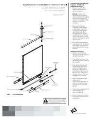
<strong>Balance</strong> ® <strong>Overhead</strong> AssemblyAssembly InstructionsAssemble units as described herein only. To do otherwise mayresult in instability. All screws, nuts and bolts must betightened securely and must be checked periodically afterassembly. Failure to assemble properly, or to secure partsmay result in assembly failure and injury.WireWorks ® Off-Module Mounted<strong>Overhead</strong> Units1. WireWorks off-module overheadunits can only be hung with the topaligned to a 12" high tile. To makehanging the unit easier, remove thetop cap or tile directly above the topof the overhead.2. Disengage the overhead locks onthe mounting brackets by lifting thetabs closest to the back of theoverhead and pulling it toward thecabinet. With the overhead lockspulled out toward the front of thecabinet, hang the top and bottom ofthe mounting brackets into thetracks of the panel’s horizontal rail.Caution: Make sure the cabinet ishanging on the horizontal track andnot on the tile.3. After the unit is hung in the track,move it to the desired position bygently lifting up while sliding it.Secure the cabinet on the tracks bypushing the overhead locks towardthe track (Figure 3).12" tilemountingbracketoverheadlockoff-modulecabinetFigure 34
<strong>Balance</strong> ®<strong>Overhead</strong> AssemblyAssembly InstructionsAssemble units as described herein only. To do otherwise mayresult in instability. All screws, nuts and bolts must betightened securely and must be checked periodically afterassembly. Failure to assemble properly, or to secure partsmay result in assembly failure and injury.load barmounting bracketload barLoad Bar Mounted <strong>Overhead</strong> Units1. To hang overhead units on a loadbar, rotate the bottom of theoverhead unit out approximately30° and hook the mounting bracketonto the top of the load bar. Rotateoverhead down until unit is securedin place (Figure 4).Note: Use the same procedurefor installing overhead units toload bars on standard walls as withload bars mounted to panel walls.load bar mountedoverhead unitFigure 45
<strong>Balance</strong> ® <strong>Overhead</strong> AssemblyAssembly InstructionsAssemble units as described herein only. To do otherwise mayresult in instability. All screws, nuts and bolts must betightened securely and must be checked periodically afterassembly. Failure to assemble properly, or to secure partsmay result in assembly failure and injury.Task Light InstallationNote: The length of the task lightdoes not have to match the size ofthe overhead unit. Shorter lightsmay be installed at the center pointof the cabinet or either side ofcenter as allowed by the slotlocations.Caution: Be sure cantileverbracket teeth are fully engaged ontothe overhead unit. Failure toassemble properly or to secureparts may result in assembly failureand injury.1. Align formed tabs in the side of thetask light with the flat tabs on thecantilever bracket. It may benecessary to remove spring clipsfrom the formed tabs in the side ofthe task light before attachingcantilever brackets (Figure 7).Note: The electrical cord from thetask light must face to the rear ofthe cabinet as illustrated when thetask light is installed.2. Flex the cantilever bracket slightlyto engage it into the formed tabsand slide forward until the hole inthe cantilever bracket snaps ontothe dimple in the task light. Repeatfor bracket at other end (Figure 7).3. Before installing the task light tothe cabinet, thread the electricalcord plug into either the centersquare hole in the overhead shelftrough back or set the cord into thecutout in the cantilever bracket asillustrated (Figure 7).4. Hook the cantilever brackets intothe slots in the trough under thecabinet which are appropriate forthe size of overhead unit and light(Figure 7).outside holecord cut-outformedtabcantileverbracketmiddle holetask light5. If power cord is threaded throughthe cord cut-out in the cantileverbracket, route the plug and cordthrough the outside square hole oneither end of the cabinet. Once thecord is routed appropriately, plug itinto an electrical source. Excesscord may be stored in the troughlocated inside the overhead.Figure 78
<strong>Balance</strong> ®<strong>Overhead</strong> AssemblyAssembly InstructionsAssemble units as described herein only. To do otherwise mayresult in instability. All screws, nuts and bolts must betightened securely and must be checked periodically afterassembly. Failure to assemble properly, or to secure partsmay result in assembly failure and injury.Shelf Divider Installation1. Orient the shelf divider asillustrated. Place the shelf dividerfront hook into the front slot of theoverhead shelf. Rotate the back ofthe shelf divider down to engage itinto the slot in the overhead back(Figure 8).2. To remove divider, reverse theabove steps.Figure 8back slotfrontshelf slotshelf dividerfront hook9
<strong>Balance</strong> ® <strong>Overhead</strong> AssemblyAssembly InstructionsAssemble units as described herein only. To do otherwise mayresult in instability. All screws, nuts and bolts must betightened securely and must be checked periodically afterassembly. Failure to assemble properly, or to secure partsmay result in assembly failure and injury.Tack Board and Tool RailAttachment BarNote: <strong>Overhead</strong> units assembledto panel systems may utilize atack board and tool rail attacheddirectly to the overhead via anattachment bar.1. Loosen the two 5 / 16-18 x 1 / 2" screwswhich attach the mounting bracketsto the underside of the overheadunit. Turn the screw out about 1 / 8" toallow for installation (Figure 9).2. Orient the attachment bar asillustrated. Align the slots in theattachment bar with the screws andslide into place. Re-tighten screwsto secure attachment bar in place(Figure 9).mountingbracket5 /16-18 x 1 /2"screwattchment barFigure 910
<strong>Balance</strong> ®<strong>Overhead</strong> AssemblyAssembly InstructionsAssemble units as described herein only. To do otherwise mayresult in instability. All screws, nuts and bolts must betightened securely and must be checked periodically afterassembly. Failure to assemble properly, or to secure partsmay result in assembly failure and injury.Ganging Plate Installationpanel-mountedoverhead unitsNote: When overhead units areinstalled side-by-side on a panelsystem, a ganging plate must beinstalled between overheads toavoid bowing of panel system.1. Orient ganging plate as illustratedunder pair of overhead units anduse two 5 / 16-18 x 1 / 2" screws tosecure plate to underside ofoverhead units (Figure 10).gangingplate5 /16-18 x 1 /2"screwFigure 1011
You make the rules.We make the rest. ®Of course <strong>KI</strong> solutions work betterfor you. They’re made for you.No one pays more attention tocustomer needs than we do.We don’t design our furniture towin awards (even though it does).We don’t rely on one-size-fits-allsolutions (even though they wouldmake our life easier). We find outwhat you need. And, we make it.The same applies to our service,distribution channels...everythingwe do. It’s all built around knowingwhat you want and giving you thechoice. <strong>KI</strong> solutions work, becausewe’re working for you.<strong>KI</strong>1330 Bellevue StreetP.O. Box 8100Green Bay, Wisconsin 54308-81001-800-424-2432www.ki.<strong>com</strong><strong>KI</strong> is a registered trademarkof Krueger International, Inc.© 2008 <strong>KI</strong>All Rights Reserved.Litho in USA.Code <strong>KI</strong>-61172R2/HT/GT/12082.5407912