Prospekt PM GB07.indd - Radius Radpol
Prospekt PM GB07.indd - Radius Radpol
Prospekt PM GB07.indd - Radius Radpol
- No tags were found...

Create successful ePaper yourself
Turn your PDF publications into a flip-book with our unique Google optimized e-Paper software.
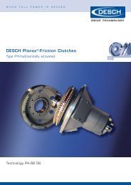
w h e n f u l l p o w e r i s n e e d e dDESCH Planox ® - <strong>PM</strong>Clutches mechanically actuatedTechnology <strong>PM</strong> 07 - GB
w h e n f u l l p o w e r i s n e e d e dPlanox ® - Friction ClutchesFig. 2Type P<strong>PM</strong>Fig. 1Type <strong>PM</strong>DESCH Planox ® -clutches are engageable/disengageable dry-friction clutcheswhich transmit the torque by friction.These clutches permit rapid accelerationof the driven machines or machinerygroups as well as safe torque transmission.Machines connected by frictionclutches are protected against damagewhich can occur by peak torques duringoperation or during the engaging/ disengagingprocess. In the case of themechanically actuated Planox ® -clutchthe lever moves the sleeve (8) whichpresses the pressure ring (7) with theadjusting ring (6) and dished spring(29) against the pressure plate by meansof three clutch levers (9). The torque,normally transmitted via the toothedring (1) to the friction discs (27), is thentransmitted by friction via the innerdiscs (3) and the pressure plate (4) tothe hub ( 2). One friction surface of theclutch forms a unit with the hub. As allthe forces inside the clutch cancel eachother when the clutch is engaged, additionalaxial loading of the adjacent shaftbearings is excluded. The built-in discsprings provide the following specialadvantages:1. Limitation of the peak torque duringthe engaging process2. Torque accurately set and limited.3. Automatic re-adjustment over a relativelylarge wear and thus low maintenance.Fig. 3 shows the torque curve of aclutch with and without dished springs.When a correctly dimensioned clutchis engaged, there is at the same timean overload protection feature againstpeak torques coming form the drivingor driven machines.Fig. 3Fig. 4 illustrates that the torque curve ofthe clutches in the range of the automaticre-adjustment of max. 1 mm is very flat.This favourable characteristic of thecurve cannot be achieved by flexiblelevers or spiral springs.Fig. 4The Planox ®friction clutchwith bellhousing and outer bearing has beendeveloped to be fitted to diesel engines.It is available as mechanically, pneumaticallyor hydraulically actuatedclutch. The complete clutch includingbearings is accommodated in a bellhousing which forms a unit with theengine after being installed. This designis a technical and economic success.The powerfully dimensioned bearingsof the output shaft in the clutch housingpermit power take-off via flexiblecouplings or pulleys. The admissibleradial loads on the output shaft endare shown as a function of speed inthe table on page 8. The flywheel andflywheel housing connections complywith the Ameican SAE standards J 617and J 621. The connecting dimensionsof the flywheel meet the Americanstandard J 620d and the VDMA standardsheet 24 380. We have adapted theconnecting dimensions of our clutchesand bell housings to these standards.Assuming the SAE standards areobserved on the engines, the Planox ® -clutches can be mounted without theuse of spacer rings. The clutch sizes fordiesel engines were selected in collabortationwith the engine manufacturers.In the event of frequent engaging/disengagingor large masses to be accelerateda check of the thermal loading of theclutch must be made (see page 13).
Parts of the Planox ® -Friction ClutchType <strong>PM</strong>W, <strong>PM</strong>F and <strong>PM</strong>AFig. 5Size 101-143Fig. 6Size 61-81Fig. 7Size 163-1831 Toothed ring2 Clutch hub3 Inner disc4 Pressure plate5 Flanged hub6 Adjusting ring7 Pressure ring8 Operating sleeve9 Clutch lever10 Actuator collar (Slip ring)11 Grub screw12 Bolt13 Roller from size 10114 Hexagon head screw15 Cylindric head screw16 Grub screw17 Pin*18 Hexagon head screw19 Dowel pin20 Dowel pin21 Dowel pin from size 10122 Retaining ring23 Locking plate *(Safety washer)24 Stop element25 Retaining ring26 Snap ring27 Friction disc28 Pressure spring29 Dished spring30 Grease nipple31 Bell housing32 Bearing cover(sealing plate in size 61-81)33 Bearing housing (from size 142)34 Operating arm35 Clamping element36 Shaft37 Cross shaft38 Operating lever39 Set collar40 Ball knob41 Key42 Key43 Antifriction bearing44 Antifriction bearing*45 Spacer bush47 Grooved nut48 Locking plate49 Cover50 Locking plate in sizes 101-18351 Dowel pin52 Hexagon head screwin sizes 142-18354 Hexagon head screw55 Hexagon nut56 Clamping element in sizes 61-112Hexagon head screw in sizes 142-183Fig. 8*57 Cylindric head sheet metal screwon sizes 61-14258 Hexagon head screw on sizes 101-183*60 Retaining ring*64 Pipe connector in sizes 163-18365 Hexagon nut in sizes 163-18366 Grease tube in sizes 163-18368 Hexagon head screw*69 Hexagon nut72 Cylindric head screw*78 Spacer bush79 Sustamid bush86 Grease nipple87 Screw plug88 Chain89 Grooved drive stud*98 Name plate99 Grooved drive stud*not shown in drawing- The designations in brackets are valid for slip ring operation (size 163-243)- For spare part orders we need serial number printed on part 2
w h e n f u l l p o w e r i s n e e d e dType <strong>PM</strong>W mechanically actuatedFig. 9 Type <strong>PM</strong>W with ball bearing shif tingSize 61-143Dimensions in mm • can be delivered ex stockSizeTorqueT Smax. Speed 1) TypeFig. 11 Type <strong>PM</strong>W and <strong>PM</strong>F with slip ring shif tingSize 163-183C D aD and D 1D and d 13)D 2D 3D 4dNm<strong>PM</strong>Wmin -1<strong>PM</strong>FPilot bore (H7) max. quantity of boltsmin -1 l x ø• 61 150 3500 3500 15 225 18 34 50 65 - 6 x M 8• 71 220 3350 3350 16 250 18 45 65 80 - 8 x M 8• 81 300 3000 3200 16 275 18 45 65 80 - 6 x M 10• 101 500 2500 3000 20 325 28 60 90 105 - 8 x M 10• 102 1000 2500 3000 44 325 28 60 90 105 - 8 x M 10• 111 700 2200 2850 20 365 28 60 90 105 - 8 x M 10• 112 1400 2200 2850 44 365 28 60 90 105 - 8 x M 10• 142 2000 1700 2500 12 480 48 90 125 155 400 8 x M 12• 143 3000 1700 2500 12 480 48 90 125 155 400 8 x M 12163 4500 1550 2200 16 530 58 100 130 170 450 8 x M 12182 4100 1400 1960 16 585 68 110 130 185 500 8 x M 16183 6150 1400 1960 16 585 68 110 130 185 500 8 x M 161) Speed is valid if the flanged hub is madeof cast iron EN-GJL-250 (GG 25). Withhigher speed (max. speed look type <strong>PM</strong>F),flange hub of EN-GJL-400-15 (GGG 40).2) Outer centering Z: Size 61 – 143 ISO j 7,Size 161 – 183 ISO js 7.3) The keyways usually are executed toDIN 6885/1. Clutch and flanged hubexecuted with 1 set screw each,displaced to the keyways by 180°.Operating systems see page 10 – 11Selection of clutches see page 12 – 14Planox ® clutch, type <strong>PM</strong>W in a combinedtransmission set for bunker boats, inclusivelyDESCH Conax ® clutches.Planox ® clutch, type <strong>PM</strong>A 143/1 fitted to a 12 cylinderdiesel engine to drive a high pressure pump.
Type <strong>PM</strong>F mechanically actuatedFig. 10 Type <strong>PM</strong>F with ball bearing shif tingSize 61-143Fig. 11 Type <strong>PM</strong>W and <strong>PM</strong>F with slip ring shif tingSize 163-183Dimensions in mm • can be delivered ex stockSize d 1G K L L 1L 2I Q S T t t 1X Z 2) Operating forceon sleeveN• 61 14,5 114 200,02 164 122 40 18 35 8 105 6 35 25,5 215,9 650• 71 14,5 114 222,25 179 122 55 18 35 8 130 6 35 25,5 241,3 750• 81 14,5 114 244,48 179 122 55 18 35 8 130 6 35 25,5 263,52 950• 101 16,5 155 295,28 244 170 70 20 49 15 160 11 45 37 314,32 1150• 102 16,5 179 295,28 268 194 70 20 49 15 160 11 45 37 314,32 1150• 111 16,5 155 333,38 244 170 70 20 49 15 160 11 45 37 352,42 1500• 112 16,5 179 333,38 268 194 70 20 49 15 160 11 45 37 352,42 1500• 142 16,5 184 438,15 313 199 110 20 50 15 215 11 45 37 466,72 1750• 143 16,5 208 438,15 337 223 110 20 50 15 215 11 45 37 466,72 1750163 20 265 488,92 404 280 120 30 65 15 230 11 70 50 517,52 1900182 20 235 542,92 386 250 130 30 65 17 250 11 70 50 571,5 2300183 20 265 542,92 416 280 130 30 65 17 250 11 70 50 571,5 2300Fig. 12Type <strong>PM</strong>WFig. 13Type <strong>PM</strong>FWeights (kg)J = mass moments of inertia (kgm²)Size Type Size Part<strong>PM</strong>W <strong>PM</strong>F 1 2 361 9,9 6,5 61 0,022 0,006 0,01271 13,8 9,2 71 0,034 0,007 0,02681 16,3 10,8 81 0,051 0,014 0,035101 34,2 23,6 101 0,134 0,023 0,130102 40,5 29,8 102 0,136 0,043 0,168111 39,3 26,4 111 0,210 0,037 0,169112 46,8 33,9 112 0,213 0,068 0,223142 88 60 142 0,686 0,515 0,513143 102 74 143 0,686 0,694 0,638163 163 123 163 1,21 1,13 1,63182 178 124 182 2,07 1,34 1,83183 206 151 183 2,07 1,80 2,26Weights and mass moments of inertia refer to max. bore.
w h e n f u l l p o w e r i s n e e d e dType <strong>PM</strong>A with outside bearingFig. 14activated lever can be fittedalternatively on both sides.Dimensions in mm resp. inchesSizeHousingconnectionSAE-SizeTorqueT smax.SpeedNm min -161 -6-5-4-3 150 3500 15 8 30 2,0475271 -6-5-4-3 220 3350 16 8 30 2,0475281 -5-4-3 300 3200 16 8 40 2,44162101 -4-3-2-1 500 3000 20 10 55 2,83572111 -4-3-2-1 700 2850 20 10 55 2,83572112 -3-2-1-0 1400 2850 44 12 60 2,83572142 -1-0-00 2000 2500 12 16 70 3,15080143 -1-0-00 3000 2500 12 16 70 3,15080163 -0-00 4500 2200 16 18 80 3,937100182 -0-00 4100 1960 16 18 80 3,937100183 -0-00 6150 1960 16 18 90 3,937100C C 1D 1) 3)D 1D 2D 3D 41)D 5dNumberofholesx Ø2 ½63,52 ½63,5376,2376,2----4101,64101,64 ⅛104,64 ⅛104,64 ⅛104,65127----7 ¼196,858203,28203,28 ¾222,258 ¾222,2510254----7 ¼184,28 ⅛206,28 ⅞225,610 ⅞276,412 ⅜314,3212 ⅜314,3216 ⅛409,416 ⅛409,418 ⅛460,219 ⅝498,319 ⅝498,3105 6x8,5 72,5 1 3/1630,2105 8x8,5 72,5 1 3/1630,2130 6x10,5 72,5 2 7/1662130 8x11 95 2 ⅛53,8130 8x11 95 1 9/1639,6140 8x11 95 1 9/1639,6180 8x13,5 118,5 125,4180 8x13,5 118,5 125,4190 8x13,5 145 ⅝15,7190 6x18 145 ⅝15,7220 6x18 145 ⅝15,7F G G 1G 22 13/1671,42 13/1671,43 15/16100,13 15/16100,13 15/16100,13 15/16100,13 15/16100,13 15/16100,13 15/16100,13 15/16100,13 15/16100,1½12,7½12,7½12,7⅝15,71 ⅛28,41 ⅛28,41 ⅛28,41 ⅛28,41 ⅛28,41 ¼31,81 ¼31,8Housing dimensionsSAE-housing 6 5 4 3 2 1 0 00Z 12)inchmm10 ½266,712 ⅜314,3214 ¼361,9516 ⅛409,5817 ⅝447,6820 ⅛511,1725 ½647,731787,4K 1inchmm11 ¼285,7513 ⅛333,371538116 ⅞428,6218 ⅜466,7220 ⅞530,2226 ¾679,4533 ½850,9D ainchmm12 ⅛307,9714355,615 ⅞403,2217 ¼450,8519 ¼488,9521 ¾552,452871134 ¾883Number of hole8Hole-Ø d 11181112111211121112111613,51613,5
Planox ® clutch type <strong>PM</strong>A 142/1 fitted to DAF diesel engine DKT 1160 to drive a bow rudder.Dimensions in mm resp. inchesSize G 3G 4J K l 1) l 11)p 1) t t 1Z 2) J 1with SAE-housing6 5 4 3 2 1 0 0061⅜9,75 9/16141,28851,57 ⅞200,02 80 400 34 1/161,58311/1617,4638 ½215,9160 175 175 195 - - - -71½12,75 9/16141,28851,58 ¾222,25 80 400 34 1/161,58311/1617,4639 ½241,3160 175 175 195 - - - -81½12,77 1/16179,388479 ⅝244,48 110 400 59 1/161,583¾19,0510 ⅜263,52- 170 220 210 - - - -101½12,78 ⅝219,0757811 ⅝295,28 110 450 78 1/161,5831⅛28,5812 ⅜314,32- - 190 205 205 225 - -111⅞22,49 ¼234,957813 ⅛333,38 110 450 94 1/161,5831 ¼31,7513 ⅞352,42- - 190 205 205 225 - -112⅞22,49 ⅝244,47510713 ⅛333,38 140 450 84 1/161,5831 ¼31,7513 ⅞352,42- - - 205 205 225 240 -142⅞22,413 ¾349,25514017 ¼438,15 140 600 79,5 ⅛3,1751 ½38,118 ⅜466,72- - - - - 260 320 325143⅞22,414 ½368,314017 ¼438,15 140 600 98,5 ⅛3,1751 ½38,118 ⅜466,72- - - - - 260 320 320163⅞22,416 11/16423,86320519 ¼488,92 170 750 79,5 ⅛3,1751 ¾44,4520 ⅜517,52- - - - - - 310 3601821 ¼31,816 11/16423,86320521 ⅜542,92 170 750 79,5 ⅛3,1751 ¾44,4522 ½571,5- - - - - - 310 3601831 ¼31,818 ¼463,5520521 ⅜542,92170 750 119,5⅛3,1751 ¾44,4522 ½571,5- - - - - - 310 3601) These dimensions are not to SAE, shaf tend dimensions to DIN 748,up to D = 50 k6 more than D = 50 m6.2) Outer centering Z:Size 61 – 143 ISO j 7;Size 163 – 183 ISO js 7Centering Z1:SAE-housing 6 – 2 ISO j 7;SAE 1 – 00 ISO js 7.Selection clutches see pages 12 – 14Allowable radial load see page 8Moments of inertia and weights seepage 5 and 8Operating systems see page 10 – 11The Planox ® clutches, type <strong>PM</strong>A with bellhousing, have been allocated to Diesel enginesa accordance with the enginge manufacturers.The engine/clutch recommendations areavailable on request. Fitting dimensions ofPlanox ® clutches are in accordance with SAEstandards J 617, J 620 d and J 621 resp.VDMA standards sheet 24 380.3) The appropriate bore should be madeaccording to ISO j 6.
w h e n f u l l p o w e r i s n e e d e dThe allowable radial load F Ris to be calculated with the tangential force FN andthe factor A according to the following formula:F R= F N· AF N=P · 9550n · r[N]Kind of drive: = Factor AOpen flat belt drive = 4Drive with tension pulley = 2,5V-belt drive = 2,5Gear or chain drive = 1,25<strong>Radius</strong> of V-belt pulley or chain drive m = rFig. 15Max.allowable load [N] for Type <strong>PM</strong>ASizeWeights [kg] for Type <strong>PM</strong>ASpeed Distance X (mm) SAE- housingmin -1 25 50 75 100 125 6 5 4 3 2 1 0 0061 1000 3500 3100 18,4 18,7 20,3 21,4 - - - -61 2000 2900 260061 3000 2500 230061 3500 2400 220071 1000 3500 3100 22,0 22,3 23,8 24,9 - - - -71 2000 2900 260071 3000 2500 230071 3350 2400 220081 1000 6000 5600 5100 - 26,5 28,3 29,5 - - - -81 2000 4900 4500 420081 3000 4300 4000 370081 3200 4200 3900 3600101 1000 14300 11500 10400 - - 56 55 58 55 - -101 2000 12500 10500 9000101 3000 10500 9500 8000111 1000 14500 12000 11000 - - 59 58 61 58 - -111 2000 12500 11000 10000111 2850 10500 10000 9500112 1000 19000 17000 13500 - - - 70 73 76 86 -112 2000 17000 15000 12500112 2850 14000 13500 12000142 500 27600 26000 24800 23600 - - - - - 142 161 179142 1000 26000 24000 22000 19200142 2000 24000 22000 20000 17500142 2500 22000 20000 19000 16000143 500 32000 26500 23900 22800 - - - - - 157 176 194143 1000 27000 24000 21000 18500143 2000 25000 22000 20000 17000143 2500 24000 22000 19500 16500163 500 35000 34000 32500 31000 29000 - - - - - - 260 297163 1000 28000 27000 26000 25000 23000163 1500 26500 26000 25000 24000 22000163 2200 24000 23000 22500 21500 20000182 500 33000 32000 30500 29500 26600 - - - - - - 263 300182 1000 31000 30000 28000 26000 22000182 1500 27500 26500 25500 23500 20000182 1960 25000 24000 23000 21000 18500183 500 48000 46000 44000 40000 37000 - - - - - - 303 339183 1000 41000 39500 38000 36500 34500183 1500 37000 35500 35000 32500 31000183 1960 34500 33000 31500 28000 27000These indications refer to 5000 hours. For 10000 hours to be multiplied by 0,8; for 15000 hours to be multiplied by 0,68.
Mechanically actuated typessurvey of typesType <strong>PM</strong>WPlanox ® mechanically actuatedshaf t to shaf t connectionType <strong>PM</strong>FPlanox ® mechanically actuatedflange to shaf t connectionType <strong>PM</strong>APlanox ® mechanically actuatedwith external bearingsType <strong>PM</strong>GPlanox ® mechanically actuatedwith incoporated gearboxInformation on requestOperating SystemsClutch CombinationsInformation on requestFig. 16Planox ® clutch type <strong>PM</strong>A 183/0 combined with a Voith turbo coupling 650 TG in one of the biggest crusher plants.
w h e n f u l l p o w e r i s n e e d e dOperating systems mechanically actuatedNote:When the clutch is running the slip ringmust be free of load. If necessary, thehand lever should be supported.Fig. 17 type SH for Planox ® <strong>PM</strong>W and <strong>PM</strong>FDimensions in mmLeversizeClutch size a b c d d 1e F gca.g 1l l 1l 2m m 1vXWeightca. kg6 – 0 61; 71; 81 110 35 18 M10 20 30 72,5 22 45 160 400 355 75 225 50 25,5 4,210 – 0 101; 102; 111; 112 140 40 25 M12 25 40 95 30,5 60 160 450 430 100 270 50 37 9,514 – 0 142; 143 140 40 25 M12 30 40 117,5 35 65 160 600 490 100 310 50 37 1316 – 0 163; 182; 183 160 45 25 M12 35 50 145 40 70 160 750 565 120 365 50 50 18Operating systems pneumatically - mechanically actuatedPneumatic elements1. Compressed air tank: Tank in which thecompressed air is stored up to a maximumpressure.2. Maintenance unit: The maintenance unitconsists of combination of filter, pressurereducing valve and line oiler.11. Activated device12. Double-acting cylinderFig. 18 Pneumatic/ mechanical actuatedsystem of a Planox ® -clutch, type <strong>PM</strong> withhand-actuated 4-way-valve.Fig. 19 Pneumatic/ mechanical actuated of aPlanox ® clutch, type <strong>PM</strong> with electromagnetic4-way-valve.13. Time control valve: The valve will delaythe release of the air and connects the workingline in change with the pressure lineresp. with the atmosphere.14. 4-way valve: serves for the alternatingconnection of the main air pipe with thecontrolled pipes resp. of the controlled pipeswith the atmosphere.15. 4-way magnetic valve: permits alternatingconnection of the conduit controlled tothe main ait piping and to the atmosphere byclosing or interrupting the circuit, respectively.Activated systems according to the activatedconditions are available on request.10
Operating systems mechanically actuatedFig. 20 Type SPWF for Planox ® <strong>PM</strong>W and <strong>PM</strong>FFig. 21 Type SPA for Planox ® <strong>PM</strong>AThe engaging forces can be taken from the appropriate clutchesDimensions in mmLever size Clutch size a a 1b c d d 1e e 1J J 16 – 0 61; 71; 81 110 610 35 18 M10 20 30 85 see page 6 – 710 – 0 101; 102; 111; 112 140 610 40 25 M12 25 40 85 see page 6 – 714 – 0 142; 143 140 610 40 25 M12 30 40 85 see page 6 – 716 – 0 163 160 610 45 25 M12 35 50 85 see page 6 – 718 – 0 182; 183 160 765 45 25 M12 35 50 95 see page 6 – 7Lever size Clutch size F F 1g g 1k l 2m m 1m ²X6 – 0 61; 71; 81 72,5 228 20 59 M 18 x 1,5 385 75 225 365 25,510 – 0 101; 102; 111; 112 95 205 30,5 76 M 18 x 1,5 465 100 270 365 3714 – 0 142; 143 117,5 255 35 81 M 18 x 1,5 525 100 310 365 3716 – 0 163 145 232 40 86 M 18 x 1,5 600 120 365 365 5018 – 0 182; 183 145 310 40 86 M 22 x 1,5 600 120 365 495 5011
Selection of clutch size accordingto mechanical loadThe torque values T S= engaging torque ofclutch (dyn.) in Nm are listed in the tables.The torque values stated can be transmittedunder constant loading. However, in the eventof varying load conditions the correspondingsafety factors „S“ must be taken into consideration:These can be found in the tables.Peak torques can occur during engagementor operation dependant on the types ofmachines being coupled. The clutch sizeshould always be orientated to the maximumload.One should distinguish between the followingcases:1. The clutch has to accelerate an insignificantmass such that nominal torque (T K) isequal to the clutch moment (T S) with regardto operating factor „S“.T K= T L· S T S[1]T K= P n· 9550 · S (Nm) [2]2. The clutch has to transmit a load torque(T L) during the engagement process itself andaccelerate a large mass.T K= T L+ T a T S[3]T K= P nSelection of clutch size according to mechanical load and friction workBesides ensuring optimum torque transmission the friction clutch must also be able to withstandthe heat generated during the engeagement process.Friction work per engagement during a on-load startQ present. Q allowed[5]Q = J · L n2182,5(J) [6]Friction work per engagement during a load startQ present. Q allowed[7]Q = J · L n2 T L+ T·a182,5 T a(J) [8]Friction work per engagement during a no-load start taking into account the mountingconditions as per fig. 23 and the ambient temperature.Q = J · n2· EL 2 (J)182,5 · E 1 · E 2[9]Friction work per engagement during a load start taking into account the mountingconditions as per fig. 23 and the ambient temperature.Q = J · L n2 T L+ T aE·· 2182,5 T aE 1 · E 3(J) [10]Friction work per hourQ/h = Q · S h(J/H) (see fig.22) [11]J · 9550 + L · n(Nm) [4]It is known that 50% of the work required for acceleration is converted to heat during thisprocess. In case if power is taken from the driving machine already during acceleration, thefriction work increases in relation of the clutch torque to the load torque.Clutches for use with driving engines anddriven machines with a high coefficient ofcyclic load variation (i.e. piston engines)should be designed according to the specifictorque requirements (a torque diagram ofthe application may help). The operatingfactors can only serve as reference values.Friction work per secondQQ/s = (J/s) [12]t sFriction work per engagement during a no-load startt s= J · n L9,55 · T(s) [13]sFriction work per engagement during a load startt s=J L · n9,55 · (T K-T L)(s) [14]Friction work in slipping clutches, when slipping speed and torque remain constantQ = T S· n · t · 0,105 (J) [15]Safety factor „S“Driving machineElectric motors Turbines,Hydraulic motorsPiston engines4 – 6 cylindersPiston engines1 – 3 cylindersReference value of operating factor „S“Load symbol of applicationU M H1,2 1,6 1,82,0 2,5 2,82,2 2,8 3,2Fig. 23 Factor E 1depending on installation resp.applicationAI = drive from inside; AA = drive from outside13
w h e n f u l l p o w e r i s n e e d e dSafety factors “S”Assignment of load characteristics according to type of working machineSSMMMSSMMMMMMGMMGMMSMSMGMMMMMGMMMMSMMMGMMGSGSDredgersBucket conveyorLanding gear (caterpillar)Landing gear (rail)Manoeuvring winchesPumpsImpellersCutter headsSlewing gearGENERATORS, TRANSFORMERSFrequency transformersGeneratorsWelding generatorsCHEMICAL INDUSTRYCooling drumsMixersAgitators (liquid material)Agitators (semi-liquid material)Drying drumsCentrifuges (light)Centrifuges (heavyOil IndustryPipeline pumpsRotary drilling equipmentCONVEYORSPit-head winchesWinding enginesjointed-band conveyorsBelt conveyors (bulk material)Belt conveyors (piece goods)Band pocket conveyorsChain conveyorsCircular conveyorsLoad elevatorsBucket conveyors for flourPassenger liftsPlate conveyorsScrew conveyorsBallast elevatorsInclined hoistsSteel belt conveyorsDrag chain conveyorsBLOWERS,VENTILATORSRotary piston blowersBlowers (axial/radial)Cooling tower fansInduced draught fansTurbo blowersBUILDING MACHINERYHoistsConcrete mixersRoad construction machinerySMSMSSMGSGSGMMMMMMMSSSSMSSGMGGMMGMMSMMSSMSMSSSSSRUBBER MACHINERYExtrudersCalendersKneading millMixersRolling millsWOOD WORKING MACHINESBarkersPlaning machinesWood working machinesSaw framesCRANESLuffing gear blockTravelling gearHoist gearSlewing gearDerricking jib gearPLASIC INDUSTRY MACHINESExtrudersCalendersMixersCrushersMETAL WORKING MACHINESPlate bending machinesPlate straightening machinesHammersMetal planning machinesPressesShearsForging pressesPunch pressesCountershafts, line shaftsMachine tools (main drives)Machine tools (auxiliary drives)FOOD INDUSTRY MACHINERYBottling and container filling machinesKneading machinesMash tubsPackaging machinesCane crushersCane cuttersCane millsSugar beet cuttersSugar beet washing machinesPAPER MACHINESCouchesGlazing cylindersPulperPulp grindersCalendersWet pressesWillowsSuction pressesSuction rollsDrying cylindersSGMSSSSSSSSSMMMMMSMSMSSSMSSSMSMSMMMSMSMSSMSMMMMPUMPSPiston pumpsCentrifugal pumps (light liquids)Centrifugal pumps (viscous liquids)Plunger pumpsPress pumpsSTONE AND CLAY WORKING MACHINESCrusherRotary ovensHammer millsBall millsTube millsBeater millsBrick pressesnTEXTILE MACHINESBatchersPrinting and dyeing machinesTanning vatsWillowsLoomsCOMPRESSORSPiston compressorsTurbo compressorsMETAL ROLLING MILLSPlate shearsManipulator for turning sheetsIngot pushersIngot and slabbing-mill trainIngot handling machineryWire drawing benchesDescaling machinesThin plate millsHeavy and medium plate millsWinding machines (strip and wire)Cold rolling millsChain tractorBillet shearsCooling bedsCross tractorRoller tables (light)Roller tables (heavy)Roller straightenersTube welding machinesTrimming shearsCropping shearsContinuous casting plantRollers adjustment driveManipulatorsLAUNDRIESTumblersWashing machinesWater treatmentAeratorsScrew pumpsThe mounting condition and the length of time taken to complete the acceleration process play adecisive role in the choice of clutch.Factor E 1Factor E 1, which represents the mounting and operating conditions, can be taken from fig. 23.Al = drive from inside; AA = drive from outsideFactor E 2The length of the process of engagement must be taken into account when clutches are used asa break, (i.e. as in the case of BAI and BAA depicted in fig. 23) Factor E 2can be taken from thediagram (fig. 24).ED = Relative time of engagement in %Fig. 24Faktor E 2depending on time of engagement for installationacc. to BAI and BAA.Factor E 3All the indicated values apply to an ambient temperature of 20°C. If the ambient temperature isabove 20°C, then the factor E 3must be taken into consideration.Faktor E 31 0,92 0,86 0,81 0,7520° 30° 40° 50° 60° CelsiusFaktor E 3depending on ambient temperature14
Questionnaire for Planox ® ClutchesInquiry No.CompanyRoadLocationRequirementsdatedpieces/ orderOffer No. datedDESCH Antriebstechnik GmbH & Co. KGPostfach 1440D-59753 ArnsbergProcessed by:A.Driving machine (Prime Mover)1) Type of driving machine (e.g. electric motor, turbine or diesel engine)2) Power kW, (PS), rotational speed min -13) Nominal torque of the driving machine Nm4) Max. torque of the driving machine Nm(pull-out torque of the electric motor)5) If a diesel engine is used: Make Type Number of cylinders6) Flywheel and flywheel-housing connection (e.g. SAE data and perhaps sketch)B. Driven machine (Driven machine)1) Type of driven machine (e.g. generator, pump or compressor)2) At what location is the clutch used? (e.g. main drive, slewing drive or suction pump)C. Clutch1) Rotational speeds before the coupling process: driving part min -1 ; driven part min -12) Engaging process*a) at a standstil b) at the full load c) Without any load3) Maximum load torque during engagement Nm4) Maximum load torque after engagement Nm5) Second-degree moment of inertia (kgm²) behind the clutch, in relation to the clutch shaft kgm²6) Is a certain acceleration time necessary ? sec.7) Number of coupling processes per hour with a uniform time distribution8) Most dense engaging sequenze in the case of non-uniform time distribution (engaging/disengaging operations pertime unit)9) Operating time of engagement clutch hours/working dayD. Which type of Operation is desired for the Present Requirement ?*1) Mechanically actuated clutch2) Remote control using a flexball switch3) Mechanically engaged clutch which is actuated by a compressed-air cylindera) Actuated by a manually operated valveb) Actuated by an electromegnetic valvec) What air pressure is available?4) Pneumatically engaged clutcha) Actuated by a manually operated valveb) Actuated by an electromegnetic valvec) What air pressure is available?E. Installation conditionsSend a drawing showing the arrangement of the clutch*Underline or put a cross against the applicable items15
w h e n f u l l p o w e r i s n e e d e dDelivery ProgrammClutchesPlanox ® friction clutchesConax ® friction clutchesCentrex ® centrifugal clutchesFlexible couplingsHadeflex ® couplingsHabix ® couplingsOrpex ® couplingsDESCH-Flex couplingsDESCH-HRC couplingsRigid couplingsPress DrivesLutex ® cluth/brake combinationsComplete press drivesGearsPlanetary gearsSpezail gearsComplete Transmission SolutionsFlywheel back gears for no-delay unitsDrive stations for stretcherLevelling unitsBack gears with engageable/disengageable clutchesBelt DrivesV-belt pulley drivesTimingFlat belt drivesV-belt pulley drives with taper bushesV-belt pulley and fly wheels tocustomers`specificationV-belt and timeings beltsBolt-on-hubsWeld-on-hubsBearingsGrease lubricated plain bearingsTelephone numbers of our head office in ArnsbergPhone FaxDES DESCH Engineering Service +49 (0) 29 32 300 - 200 300 - 811DPC DESCH Power Transmission Center +49 (0) 29 32 300 - 218 300 - 830DCT DESCH Clutch Technology +49 (0) 29 32 300 - 170 300 - 50DGP DESCH Gearbox and Press Drives +49 (0) 29 32 300 - 153 300 - 811DESCH is a memberDESCH Antriebstechnik GmbH & Co. KGPostfach 14 40D-59753 Arnsberg/GermanyKleinbahnstraße 21D-59759 Arnsberg/GermanyTelefon +49 (0) 29 32 - 3 00 - 0Fax +49 (0) 29 32 - 3 00 - 899Internet www.desch.deE-mail info@desch.deTechnical changes reserved16DESCH Drive TechnologyLimited Partnership240 Shearson CrescentCambridge, OntarioCanada N 1T 1J6Telefon +1800 - 2 63 18 66+1519 - 6 21 45 60Fax +1519 - 6 23 11 69Internet www.desch.on.caE-mail desch@desch.on.ca© DESCH Antriebstechnik GmbH & Co. KG · <strong>PM</strong> 07 - GBDESCH Drive TechnologyUfficio di rappresentanza in ItaliaVia Cavriana, 3I-20134 MilanoTelefon +3902 - 7 39 12 80Fax +3902 - 7 39 12 81Internet www.desch.deE-mail desch.italia@desch.dewww.desch.de