Why Did the World Trade Center Collapse?--Simple Analysis ...
Why Did the World Trade Center Collapse?--Simple Analysis ...
Why Did the World Trade Center Collapse?--Simple Analysis ...

Create successful ePaper yourself
Turn your PDF publications into a flip-book with our unique Google optimized e-Paper software.
By Zdeněk P. Bažant 1 , Fellow ASCE, and Yong Zhou 2Abstract: This paper 3 presents a simplified approximate analysis of <strong>the</strong> overall collapse of <strong>the</strong> towersof <strong>World</strong> <strong>Trade</strong> <strong>Center</strong> in New York on September 11, 2001. The analysis shows that if prolongedheating caused <strong>the</strong> majority of columns of a single floor to lose <strong>the</strong>ir load carrying capacity, <strong>the</strong> wholetower was doomed. Despite optimistic simplifying assumptions, <strong>the</strong> structural resistance is found to bean order of magnitude less than necessary for survival.Introduction and Failure ScenarioThe 110-story towers of <strong>the</strong> <strong>World</strong> <strong>Trade</strong> <strong>Center</strong> were designed to withstand as a whole <strong>the</strong> forcescaused by a horizontal impact of a large commercial aircraft (Appendix I). So why did a totalcollapse occur? The cause was <strong>the</strong> dynamic consequence of <strong>the</strong> prolonged heating of <strong>the</strong> steelcolumns to very high temperature. The heating lowered <strong>the</strong> yield strength and caused viscoplastic(creep) buckling of <strong>the</strong> columns of <strong>the</strong> framed tube along <strong>the</strong> perimeter of <strong>the</strong> tower and of <strong>the</strong>columns in <strong>the</strong> building core. The likely scenario of failure is approximately as follows.In stage 1 (Fig. 1), <strong>the</strong> conflagration caused by <strong>the</strong> aircraft fuel spilled into <strong>the</strong> structure causes<strong>the</strong> steel of <strong>the</strong> columns to be exposed to sustained temperatures apparently exceeding 800 ◦ C. Theheating is probably accelerated by a loss of <strong>the</strong> protective <strong>the</strong>rmal insulation of steel during <strong>the</strong>initial blast. At such temperatures, structural steel suffers a decrease of yield strength and exhibitssignificant viscoplastic deformation (i.e., creep—an increase of deformation under sustained load).This leads to creep buckling of columns (e.g., Bažant and Cedolin 1991, Sec. 9), which consequentlylose <strong>the</strong>ir load carrying capacity (stage 2). Once more than about a half of <strong>the</strong> columns in <strong>the</strong> criticalfloor that is heated most suffer buckling (stage 3), <strong>the</strong> weight of <strong>the</strong> upper part of <strong>the</strong> structureabove this floor can no longer be supported, and so <strong>the</strong> upper part starts falling down onto <strong>the</strong>lower part below <strong>the</strong> critical floor, ga<strong>the</strong>ring speed until it impacts <strong>the</strong> lower part. At that moment,<strong>the</strong> upper part has acquired an enormous kinetic energy and a significant downward velocity. Thevertical impact of <strong>the</strong> mass of <strong>the</strong> upper part onto <strong>the</strong> lower part (stage 4) applies enormous verticaldynamic load on <strong>the</strong> underlying structure, far exceeding its load capacity, even if it is not heated.This causes failure of an underlying multi-floor segment of <strong>the</strong> tower (stage 4), in which <strong>the</strong> failureof <strong>the</strong> connections of <strong>the</strong> floor-carrying trusses to <strong>the</strong> columns is ei<strong>the</strong>r accompanied or quicklyfollowed by buckling of <strong>the</strong> core columns and overall buckling of <strong>the</strong> framed tube, with <strong>the</strong> bucklesprobably spanning <strong>the</strong> height of many floors (stage 5, at right), and <strong>the</strong> upper part possibly gettingwedged inside an emptied lower part of <strong>the</strong> framed tube (stage 5, at left). The buckling is initiallyplastic but quickly leads to fracture in <strong>the</strong> plastic hinges. The part of building lying beneath is <strong>the</strong>nimpacted again by an even larger mass falling with a greater velocity, and <strong>the</strong> series of impacts andfailures <strong>the</strong>n proceeds all <strong>the</strong> way down (stage 5).1 Walter P. Murphy Professor of Civil Engineering and Materials Science, Northwestern University, EvanstonIllinois 60208; z-bazant@northwestern.edu.2 Graduate Research Assistant, Northwestern University.3 Republication, with permission, of an artical submitted to ASCE for publication (in orginal form with Eqs. 1 and 2 on September13, 2001, in an expanded version with Eq.3without <strong>the</strong> appendices on September 22, and with appendices on September 28).Posted since September 14 athttp://www.civil.nothwestern.edu/news, http://www3.tam.uiuc.edu/news/200109wtc/, andhttp://math.mit.edu/\~{\vspace{1mm}}bazant, where fur<strong>the</strong>r updates of <strong>the</strong> analysis might be posted.
of column displacements across <strong>the</strong> tower is almost linear, like for a rigid body. If, however, <strong>the</strong>upper part spanned only a few floors (say, 3 to 6), <strong>the</strong>n it could be so flexible that different columngroups of <strong>the</strong> upper part could move down separately at different times, producing a series of smallimpacts that would not be fatal (in <strong>the</strong>ory, if people could have escaped from <strong>the</strong> upper part of<strong>the</strong> tower, <strong>the</strong> bottom part of <strong>the</strong> tower could have been saved if <strong>the</strong> upper part were bombed,exploded or weakened by some ‘smart’ structure system to collapse onto <strong>the</strong> lower part graduallyas a mass of rubble, instead of impacting it instantly as an almost rigid body).<strong>Analysis</strong> of Inelastic Energy DissipationThe inelastic deformation of <strong>the</strong> steel of <strong>the</strong> towers involves plasticity and fracture. Since we are notattempting to model <strong>the</strong> details of <strong>the</strong> real failure mechanism but seek only to prove that <strong>the</strong> towersmust have collapsed and do so in <strong>the</strong> way seen (Engineering 2001, American 2001), we will hereneglect fracture, even though <strong>the</strong> development of fractures is clearly discerned in <strong>the</strong> photographsof <strong>the</strong> collapse. Assuming <strong>the</strong> steel to behave plastically, with unlimited ductility, we are making<strong>the</strong> most optimistic assumption with regard to <strong>the</strong> survival capacity of <strong>the</strong> towers (in reality, <strong>the</strong>plastic hinges, especially <strong>the</strong> hinges at column connections, must have fractured, and done so atrelatively small rotation, causing <strong>the</strong> load capacity to drop drastically).The basic question to answer is: Can <strong>the</strong> fall of <strong>the</strong> upper part be arrested by energy dissipationduring plastic buckling which follows <strong>the</strong> initial elastic deformation? Many plastic failure mechanismscould be considered, for example: (a) <strong>the</strong> columns of <strong>the</strong> underlying floor buckle locally (Fig.1, stage 2); (b) <strong>the</strong> floor-supporting trusses are sheared off at <strong>the</strong> connections to <strong>the</strong> framed tubeand <strong>the</strong> core columns and fall down within <strong>the</strong> tube, depriving <strong>the</strong> core columns and <strong>the</strong> framedtube of lateral support, and thus promoting buckling of <strong>the</strong> core columns and <strong>the</strong> framed tubeunder vertical compression (Fig. 1, stage 4, Fig. 2c); or (c) <strong>the</strong> upper part is partly wedged within<strong>the</strong> emptied framed tube of <strong>the</strong> lower part, pushing <strong>the</strong> walls of <strong>the</strong> framed tube apart (Fig. 1,stage 5). Although each of <strong>the</strong>se mechanism can be shown to lead to total collapse, a combinationof <strong>the</strong> last two seems more realistic (<strong>the</strong> reason: multi-story pieces of <strong>the</strong> framed tube, with nearlystraight boundaries apparently corresponding to plastic hinge lines causing buckles on <strong>the</strong> framedtube wall, were photographed falling down; see, e.g., Engineering 2001, American 2001).Regardless of <strong>the</strong> precise failure mode, experience with buckling indicates that while many elasticbuckles simultaneously coexist in an axially compressed tube, <strong>the</strong> plastic deformation localizes(because of plastic bifurcation) into a single buckle at a time (Fig. 1, stage 4; Fig. 2c), and so<strong>the</strong> buckles must fold one after ano<strong>the</strong>r. This is also true of rapid buckling after impact. Thus, atleast one plastic hinge, and no more than four plastic hinges, per column line are needed to operatesimultaneously in order to allow <strong>the</strong> upper part to continue moving down (Fig. 2b, Bažant andCedolin 1991) (this is also true if <strong>the</strong> columns of only one floor are buckling at a time). At <strong>the</strong> end,<strong>the</strong> sum of <strong>the</strong> rotation angles θ i (i = 1, 2, ..) of <strong>the</strong> hinges on one column line, ∑ θ i , cannot exceed2π (Fig. 2b). This upper-bound value, which is independent of <strong>the</strong> number of floors spanned by<strong>the</strong> buckle, is used in <strong>the</strong> present calculations since, in regard to survival, it represents <strong>the</strong> mostoptimistic hypo<strong>the</strong>sis, maximizing <strong>the</strong> plastic energy dissipation.Calculating <strong>the</strong> dissipation per column line of <strong>the</strong> framed tube as <strong>the</strong> plastic bending momentM p of one column (Jirásek and Bažant 2002), times <strong>the</strong> combined rotation angle ∑ θ i = 2π (Fig.2b), and multiplying this by <strong>the</strong> number of columns, one concludes that <strong>the</strong> plastically dissipatedenergy W p is, optimistically, of <strong>the</strong> order of 0.5 GN m (for lack of information, certain detailssuch as <strong>the</strong> wall thickness of steel columns, were estimated by carrying out approximate designcalculations for this building).To attain <strong>the</strong> combined rotation angle ∑ θ i = 2π of <strong>the</strong> plastic hinges on each column line, <strong>the</strong>upper part of <strong>the</strong> building must move down by <strong>the</strong> additional distance of one buckle, which is atleast one floor below <strong>the</strong> floor where <strong>the</strong> collapse started. So <strong>the</strong> additional release of gravitationalpotential energy W g ≥ mg · 2h ≈ 2 × 2.1 GN m = 4.2 GN m. To arrest <strong>the</strong> fall, <strong>the</strong> kinetic energyof <strong>the</strong> upper part, which is equal to <strong>the</strong> potential energy release for a fall through <strong>the</strong> height ofat least two floors, would have to be absorbed by <strong>the</strong> plastic hinge rotations of one buckle, i.e.,W g /W p would have to be less than 1. Ra<strong>the</strong>r,W g /W p ≈ 8.4 (3)
if <strong>the</strong> energy dissipated by <strong>the</strong> columns of <strong>the</strong> critical heated floor is neglected. If <strong>the</strong> first bucklespans over n floors (3 to 10 seems likely), this ratio is about n times larger. So, even under byfar <strong>the</strong> most optimistic assumptions, <strong>the</strong> plastic deformation can dissipate only a small part of <strong>the</strong>kinetic energy acquired by <strong>the</strong> upper part of building.When <strong>the</strong> next buckle with its group of plastic hinges forms, <strong>the</strong> upper part has already traveledmany floors down and has acquired a much higher kinetic energy; <strong>the</strong> percentage of <strong>the</strong> kineticenergy dissipated plastically is <strong>the</strong>n of <strong>the</strong> order of 1%. The percentage continues to decreasefur<strong>the</strong>r as <strong>the</strong> upper part moves down. If fracturing in <strong>the</strong> plastic hinges were considered, a stillsmaller (in fact much smaller) energy dissipation would be obtained. So <strong>the</strong> collapse of <strong>the</strong> towermust be an almost free fall. This conclusion is supported by <strong>the</strong> observation that <strong>the</strong> duration of<strong>the</strong> collapse of <strong>the</strong> tower, observed to be 9 s, was about <strong>the</strong> same as <strong>the</strong> duration of a free fall in avacuum from <strong>the</strong> tower top (416 m above ground) to <strong>the</strong> top of <strong>the</strong> final heap of debris (about 25m above ground), which is t = √ 2 (416m − 25m)/g = 8.93 s. It fur<strong>the</strong>r follows that <strong>the</strong> brunt ofvertical impact must have gone directly into <strong>the</strong> columns of <strong>the</strong> framed tube and <strong>the</strong> core and thatany delay ∆t of <strong>the</strong> front of collapse of <strong>the</strong> framed tube behind <strong>the</strong> front of collapsing (‘pancaking’)floors must have been negligible, or else <strong>the</strong> duration of <strong>the</strong> total collapse of <strong>the</strong> tower, 9 s + ∆t,would have been significantly longer than 9 s. However, even for a short delay ∆t, <strong>the</strong> floors shouldhave acted like a piston running down through an empty tube, which helps to explain <strong>the</strong> smokeand debris that was seen being expelled laterally from <strong>the</strong> collapsing tower.Problems of Disaster Mitigation and DesignDesigning tall buildings to withstand this sort of attack seems next to impossible. It would requirea much thicker insulation of steel, with blast-resistant protective cover. Replacing <strong>the</strong> rectangularframed tube by a hardened circular monolithic tube with tiny windows might help to deflect muchof <strong>the</strong> debris and fuel from an impacting aircraft sideways, but regardless of cost, who would wantto work in such a building?The problems appear to be equally severe for concrete columns because concrete heated tosuch temperatures undergoes explosive <strong>the</strong>rmal spalling, <strong>the</strong>rmal fracture and disintegration dueto dehydration of hardened cement paste (e.g., Bažant and Kaplan 1996). These questions arisenot only for buildings supported on many columns but also for <strong>the</strong> recent designs of tall buildingswith a massive monolithic concrete core functioning as a tubular mast. These recent designs usehigh-strength concrete which, however, is even more susceptible to explosive <strong>the</strong>rmal spalling and<strong>the</strong>rmal fracture than normal concrete. The use of refractory concretes as <strong>the</strong> structural materialinvites many open questions (Bažant and Kaplan 1996). Special alloys or various refractory ceramiccomposites may of course function at such temperatures, but <strong>the</strong> cost would increase astronomically.It will never<strong>the</strong>less be appropriate to initiate research on materials and designs that wouldpostpone <strong>the</strong> collapse of <strong>the</strong> building so as to extend <strong>the</strong> time available for evacuation, provide ahardened and better insulated stairwell, or even prevent collapse in <strong>the</strong> case of a less severe attacksuch as an off-center impact or <strong>the</strong> impact of an aircraft containing little fuel.Lessons should be drawn for improving <strong>the</strong> safety of building design in <strong>the</strong> case of lesser disasters.For instance, in view of <strong>the</strong> progressive dynamic collapse of a 20-story section of 22-story RonanPoint apartments (Canning Town, U.K., 1968), caused by a gas explosion in one upper floor (Levyand Salvadori 1992), <strong>the</strong> following design principle, enforcing a sufficient degree of redundancy,may be desirable: If only a certain judiciously specified minority of <strong>the</strong> columns or column-floorconnections at one floor is removed, <strong>the</strong> mass that may fall down from <strong>the</strong> superior structure mustbe so small that its impact on <strong>the</strong> underlying structure would not cause dynamic overload.Closing CommentsOnce accurate computer calculations are carried out, various details of <strong>the</strong> failure mechanism willdoubtless be found to differ from <strong>the</strong> present simplifying hypo<strong>the</strong>ses. Errors by a factor of 2would not be terribly surprising, but that would hardly matter since <strong>the</strong> present analysis revealsorder-of-magnitude differences between <strong>the</strong> dynamic loads and <strong>the</strong> structural resistance.There have been many interesting, but intuitive, competing explanations of <strong>the</strong> collapse. Todecide <strong>the</strong>ir viability, however, it is important to do at least some crude calculations. For example,
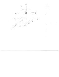
it has been suggested that <strong>the</strong> connections of <strong>the</strong> floor-supporting trusses to <strong>the</strong> framed tubecolumns were not strong enough. Maybe <strong>the</strong>y were not, but even if <strong>the</strong>y were it would have madeno difference, as shown by <strong>the</strong> present simple analysis.The main purpose of <strong>the</strong> present analysis is to prove that <strong>the</strong> whole tower must have collapsedif <strong>the</strong> fire destroyed <strong>the</strong> load capacity of <strong>the</strong> majority of columns of a single floor. This purposejustifies <strong>the</strong> optimistic simplifying assumptions regarding survival made at <strong>the</strong> outset, which includeunlimited plastic ductility (i.e., absence of fracture), uniform distribution of impact forces among<strong>the</strong> columns, disregard of various complicating details (e.g., <strong>the</strong> possibility that <strong>the</strong> failures offloor-column connections and of core columns preceded <strong>the</strong> column and tube failure, or that <strong>the</strong>upper tube got wedged inside <strong>the</strong> lower tube), etc. If <strong>the</strong> tower is found to fail under <strong>the</strong>se veryoptimistic assumptions, it will certainly be found to fail when all <strong>the</strong> detailed mechanisms areanalyzed, especially since <strong>the</strong>re are order-of-magnitude differences between <strong>the</strong> dynamic loads and<strong>the</strong> structural resistance.An important puzzle at <strong>the</strong> moment is why <strong>the</strong> adjacent 46-story building, into which nosignificant amount of aircraft fuel could have been injected, collapsed as well. Despite <strong>the</strong> lack ofdata at present, <strong>the</strong> likely explanation seems to be that high temperatures (though possibly wellbelow 800 ◦ C) persisted on at least one floor of that building for a much longer time than specified by<strong>the</strong> current fire code provisions. The critical floor was probably <strong>the</strong> ground floor, heated by a hugeburning gas leak. The collapse mechanism would be similar, except for a reverse direction—<strong>the</strong>failure front would propagate into <strong>the</strong> upper floors as <strong>the</strong>y impacted <strong>the</strong> ground.Appendix I. Elastic Dynamic Response to Aircraft ImpactA simple estimate based on <strong>the</strong> preservation of <strong>the</strong> combined momentum of <strong>the</strong> impacting Boeing767-200 (∼ 179,000 kg × 550 km/h) and <strong>the</strong> momentum of <strong>the</strong> equivalent mass M eq of <strong>the</strong> interactingupper part of <strong>the</strong> tower (∼ 141·10 6 × v 0 ) indicates that <strong>the</strong> initial average velocity v 0 impartedto <strong>the</strong> upper part of <strong>the</strong> tower was only about 0.7 km/h = 0.19 m/s. Mass M eq , which is imaginedas a concentrated mass mounted at <strong>the</strong> height of <strong>the</strong> impacted floor on a massless free-standingcantilever with <strong>the</strong> same bending stiffness as <strong>the</strong> tower (Fig. 2d), has been calculated from <strong>the</strong>condition that its free vibration period be equal to <strong>the</strong> first vibration period of <strong>the</strong> tower, which hasbeen roughly estimated as T 1 = 14 s (M eq ≈ 44% of <strong>the</strong> mass of <strong>the</strong> whole tower). The dynamicresponse after impact may be assumed to be dominated by <strong>the</strong> first free vibration mode, of periodT 1 . Therefore, <strong>the</strong> maximum horizontal deflection w 0 = v 0 T 1 /2π ≈ 0.4 m, which is well within <strong>the</strong>design range of wind-induced elastic deflections. So it is not surprising that <strong>the</strong> aircraft impact perse damaged <strong>the</strong> tower only locally.The <strong>World</strong> <strong>Trade</strong> <strong>Center</strong> was designed for an impact of Boeing 707-320 ra<strong>the</strong>r than Boeing767-320. But note that <strong>the</strong> maximum takeoff weight of that older, less efficient, aircraft is only 15%less than that of Boeing 767-200. Besides, <strong>the</strong> maximum fuel tank capacity of that aircraft is only4% less. These differences are well within <strong>the</strong> safety margins of design. So <strong>the</strong> observed responseof <strong>the</strong> towers proves <strong>the</strong> correctness of <strong>the</strong> original dynamic design. What was not considered indesign was <strong>the</strong> temperature that can develop in <strong>the</strong> ensuing fire. Here <strong>the</strong> lulling experience from1945 might have been deceptive; that year, a two-engine bomber (B-25), flying in low clouds toNewark at about 400 km/h, hit <strong>the</strong> Empire State Building (381 m tall, built in 1932) at <strong>the</strong> 79thfloor (278 m above ground)—<strong>the</strong> steel columns (much heavier than in modern buildings) sufferedno significant damage, and <strong>the</strong> fire remained confined essentially to two floors only (Levy andSalvadori 1992).Appendix II. <strong>Why</strong> <strong>Did</strong>n’t <strong>the</strong> Upper Part Pivot About Its Base?Since <strong>the</strong> top part of <strong>the</strong> South Tower tilted (Fig. 3a), many people wonder: <strong>Why</strong> didn’t <strong>the</strong> upperpart of <strong>the</strong> tower fall to <strong>the</strong> side like a tree, pivoting about <strong>the</strong> center of <strong>the</strong> critical floor? (Fig. 3b)To demonstrate why, and thus to justify our previous neglect of tilting, is an elementary exercisein dynamics.Assume <strong>the</strong> center of <strong>the</strong> floor at <strong>the</strong> base of <strong>the</strong> upper part (Fig. 3b) to move for a whilenei<strong>the</strong>r laterally nor vertically, i.e., act as a fixed pivot. Equating <strong>the</strong> kinetic energy of <strong>the</strong> upperpart rotating as a rigid body about <strong>the</strong> pivot at its base (Fig. 3c) to <strong>the</strong> loss of <strong>the</strong> gravitational
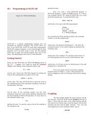
potential energy of that part (which is here simpler than using <strong>the</strong> Lagrange equations of motion),we have mg(1 − cos θ)H 1 /2 = (m/2H 1 ) ∫ H 10( ˙θx) 2 dx where x is <strong>the</strong> vertical coordinate (Fig. 3c).This provides√3g3g˙θ = (1 − cos θ), ¨θ = sin θ (4)H 1 2H 1where θ = rotation angle of <strong>the</strong> upper part, H 1 = its height, and <strong>the</strong> superposed dots denote timederivatives (Fig. 3c).Considering <strong>the</strong> dynamic equilibrium of <strong>the</strong> upper part as a free body, acted upon by distributedinertia forces and a reaction with horizontal component F at base (Fig. 3d), one obtains F =∫ H10(m/H 1 ) ¨θ cos θ xdx = 1 2 H 1m ¨θ cos θ = 3 8mg sin 2θ. Evidently, <strong>the</strong> maximum horizontalreaction during pivoting occurs for θ = 45 ◦ , and soF max = 3 8 mg = 3 8 P 0 ≈ 320 MN (5)where, for <strong>the</strong> upper part of South Tower, m ≈ 87 · 10 6 kg.Could <strong>the</strong> combined plastic shear resistance F p of <strong>the</strong> columns of one floor (Fig. 3f) sustainthis horizontal reaction? For plastic shear, <strong>the</strong>re would be yield hinges on top and bottom of eachresisting column; Fig. 3e (again, aiming only at an optimistic upper bound on resistance, we neglectfracture). The moment equilibrium condition for <strong>the</strong> column as a free body shows that each columncan at most sustain <strong>the</strong> shear force F 1 = 2M p /h 1 where h 1 ≈ 2.5 m = effective height of column,and M p ≈ 0.3 MN m = estimated yield bending moment of one column, if cold. Assuming that<strong>the</strong> resisting columns are only those at <strong>the</strong> sides of <strong>the</strong> framed tube normal to <strong>the</strong> axis of rotation,which number about 130, we get F p ≈ 130F 1 ≈ 31 MN. So, <strong>the</strong> maximum horizontal reaction topivoting would cause <strong>the</strong> overload ratioF max /F p ≈ 10.3 (6)if <strong>the</strong> resisting columns were cold. Since <strong>the</strong>y are hot, <strong>the</strong> horizontal reaction to pivoting wouldexceed <strong>the</strong> shear capacity of <strong>the</strong> heated floor still much more (and far more if fracture were considered).Since F is proportional to sin 2θ, its value becomes equal to <strong>the</strong> plastic limit when sin 2θ =1/10.3. From this we fur<strong>the</strong>r conclude that <strong>the</strong> reaction at <strong>the</strong> base of <strong>the</strong> upper part of SouthTower must have begun shearing <strong>the</strong> columns plastically already at <strong>the</strong> inclinationθ ≈ 2.8 ◦ (7)The pivoting of <strong>the</strong> upper part must have started by an asymmetric failure of <strong>the</strong> columns on oneside of building, but already at this very small angle <strong>the</strong> dynamic horizontal reaction at <strong>the</strong> base of<strong>the</strong> upper part must have reduced <strong>the</strong> vertical load capacity of <strong>the</strong> remaining columns of <strong>the</strong> criticalfloor (even if those were not heated). That must have started <strong>the</strong> downward motion of <strong>the</strong> top partof <strong>the</strong> South Tower, and afterwards its motion must have become predominantly vertical. Hence,a vertical impact of <strong>the</strong> upper part onto <strong>the</strong> lower part must have been <strong>the</strong> dominant mechanism.Finally note that <strong>the</strong> horizontal reaction F max is proportional to <strong>the</strong> weight of <strong>the</strong> pivoting part.Therefore, if a pivoting motion about <strong>the</strong> center of some lower floor were considered, F max wouldbe still larger.Appendix III. Plastic Load-Shortening Diagram of ColumnsNormal design deals only with initial bifurcation and small deflections, in which <strong>the</strong> diagram ofload versus axial shortening of an elasto-plastic column exhibits hardening ra<strong>the</strong>r than softening.However, <strong>the</strong> columns of <strong>the</strong> towers suffered very large plastic deflections, for which this diagramexhibits pronounced softening. Fig. 5 shows this diagram as estimated for <strong>the</strong>se towers. Thediagram begins with axial shortening due to plastic yielding at load P 0 1 = A 1f y where A 1 = crosssectionarea of one column and f y = yield limit of steel. At <strong>the</strong> axial shortening of about 3%, <strong>the</strong>reis a plastic bifurcation (if imperfections are ignored). After that, undeflected states are unstable andthree plastic hinges (Fig. 5) must form (if we assume, optimistically, <strong>the</strong> ends to be fixed). From
<strong>the</strong> condition of moment equilibrium of <strong>the</strong> half-column as a free body (Fig. 5), <strong>the</strong> axial load <strong>the</strong>nis P 1 = 4M p /L sin θ, while, from <strong>the</strong> buckling geometry, <strong>the</strong> axial shortening is u = L(1 − cos θ),where L = distance between <strong>the</strong> end hinges. Eliminating plastic hinge rotation θ, we find that <strong>the</strong>plastic load-shortening diagram (including <strong>the</strong> pre- and post-bifurcation states) is given by(P 1 (u) = min4M pL √ 1 − [1 − (u/L)] 2 , P 0 1which defines <strong>the</strong> curve plotted in Fig. 5. This curve is an optimistic upper bound since, in reality,<strong>the</strong> plastic hinges develop fracture (e.g., Bažant and Planas 1998), and probably do so already atra<strong>the</strong>r small rotations. The area under this curve represents <strong>the</strong> dissipated energy.If it is assumed that one or several floor slabs above <strong>the</strong> critical heated floor collapsed first, <strong>the</strong>n<strong>the</strong> L to be substituted in (8) is much longer than <strong>the</strong> height of columns of one floor. Consequently,P 1 (u) becomes much smaller (and <strong>the</strong> Euler elastic critical load for buckling may even become lessthan <strong>the</strong> plastic load capacity, which is far from true when L is <strong>the</strong> column height of a single floor).It has been suggested that <strong>the</strong> inelastic deformation of columns might have ‘cushioned’ <strong>the</strong> initialdescent of <strong>the</strong> upper part, making it almost static. However, this is impossible because, for gravityloading, a softening of <strong>the</strong> load-deflection diagram (Fig. 5) always causes instability and precludesstatic deformation (Bažant and Cedolin 1991, Chpt. 10 and 13). The downward acceleration of <strong>the</strong>upper part is ü = N[P 0 1 − P 1(u)]/m where N = number of columns and, necessarily, P 0 1 = mg/N.This represents a differential equation for u as a function of time t, and its integration shows that<strong>the</strong> time that <strong>the</strong> upper part takes to fall through <strong>the</strong> height of one story is, for cold columns, onlyabout 6% longer than <strong>the</strong> duration of a free fall from that height, which is 0.87 s. For hot columns,<strong>the</strong> difference is of course much less than 6%. So <strong>the</strong>re is hardly any ‘cushioning’.ReferencesAmerican Media Specials, Vol. II, No. 3, September 2001, J. Lynch, ed., Boca Raton, Florida.Bažant, Z.P., and Cedolin, L. (1991). Stability of structures: Elastic, inelastic, fracture and damage<strong>the</strong>ories. Oxford University Press, New York.Bažant, Z.P., and Kaplan, M.F. (1996). Concrete at high temperatures. Longman – Addison-Wesley,London.Bažant, Z.P., and Planas, J. (1998). Fracture and size effect of concrete and o<strong>the</strong>r quasibrittlematerials. CRC Press, Boca Raton, Florida, and London.Bažant, Z.P. (2001a). ”<strong>Why</strong> did <strong>the</strong> <strong>World</strong> <strong>Trade</strong> <strong>Center</strong> collapse?” SIAM News (Society forIndustrial and Applied Ma<strong>the</strong>matics, M.I.T., Cambridge), 34 (8), October (submitted Sept.14).Bažant, Z.P. (2001b). “Anatomy of Twin Towers <strong>Collapse</strong>.” Science and Technology (part ofHospodarske Noviny, Prague) No. 186, Sept. 25, p.1.Jirásek, M., and Bažant, Z.P. (2002). Inelastic <strong>Analysis</strong> of Structures. J. Wiley and Sons, Londonand New York.Levy, M., and Salvadori, M. (1992). <strong>Why</strong> buildings fall down. W.W. Norton and Co., New York.“Massive assault doomed towers” (editorial), Engineering News Record 247 (12), September 17,2001, pp. 10–13.Captions:Fig. 1 Stages of collapse of <strong>the</strong> building (floor height exaggerated).Fig. 2 (a) Model for impact of upper part on lower part of building. (b) Plastic buckling mechanismon one column line. (c) Combination of plastic hinges creating a buckle in <strong>the</strong> tube wall (separatedprobably by a distance of several stories). (d) Equivalent mass M eq on a massless column vibratingat <strong>the</strong> same frequency.Fig. 3 Pivoting of upper part of tower about its base; (a,b) with and without horizontal shear at base;(c) model for simplified analysis; (d) free-body diagram with inertia forces; (d,e) plastic horizontalshearing of columns in critical floor at base.Fig. 4 Scenario of tilting of upper part of building (South Tower).Fig. 5 (a) Plastic buckling of columns; (b) plastic hinge mechanism; (b) free-body diagram; (d)dimensionless diagram of load P 1 versus axial shortening u of columns of <strong>the</strong> towers if <strong>the</strong> effects offracture and heating are ignored; and (e) <strong>the</strong> beginning of this diagrams in an expanded horizontal scale(imperfections neglected).)(8)
P 1P 1u MpP 1L=2LefhθLθL/2MpP 1a. b. c.1shortening1shorteningPLASTICPLASTIC0P1/P10.5buckling0bucklingP1/P10.500 0.5 1u/L0 0.04u/Ld. e.0Fig. 5