Quidway AR 18 Series Routers Installation Manual.pdf - Index of
Quidway AR 18 Series Routers Installation Manual.pdf - Index of
Quidway AR 18 Series Routers Installation Manual.pdf - Index of

You also want an ePaper? Increase the reach of your titles
YUMPU automatically turns print PDFs into web optimized ePapers that Google loves.
Intended AudienceThe manual is intended for the following readers:• Network engineers• Network administrators• Customers who are familiar with network fundamentalsConventionsThe manual uses the following conventions:I. General conventionsConventionDescriptionArialArial NarrowBoldfaceCourier NewNormal paragraphs are in Arial.Warnings, Cautions, Notes and Tips are in Arial Narrow.Headings are in Boldface.Terminal Display is in Courier New.II. GUI conventionsConventionDescription< >[ ]/Button names are inside angle brackets. For example, click the button.Window names, menu items, data table and field names are inside squarebrackets. For example, pop up the [New User] window.Multi-level menus are separated by forward slashes. For example,[File/Create/Folder].III. Keyboard operationFormatDescriptionPress the key with the key name inside angle brackets. For example,, , , or .Press the keys concurrently. For example, means the threekeys should be pressed concurrently.Press the keys in turn. For example, means the two keys shouldbe pressed in turn.
IV. SymbolsEye-catching symbols are also used in the manual to highlight the points worthy <strong>of</strong>special attention during the operation. They are defined as follows:operation.Caution, Warning, Danger: Means reader be extremely careful during the Note, Comment, Tip, Knowhow, Thought: Means a complementary description.Environmental ProtectionThis product has been designed to comply with the requirements on environmentalprotection. For the proper storage, use and disposal <strong>of</strong> this product, national laws andregulations must be observed.
<strong>Installation</strong> <strong>Manual</strong><strong>Quidway</strong> <strong>AR</strong> <strong>18</strong> <strong>Series</strong> <strong>Routers</strong>Table <strong>of</strong> ContentsTable <strong>of</strong> ContentsChapter 1 Router Overview .......................................................................................................... 1-11.1 Introduction ........................................................................................................................ 1-11.2 Hardware Features ............................................................................................................ 1-21.2.1 <strong>AR</strong> <strong>18</strong>-12 Router ..................................................................................................... 1-21.2.2 <strong>AR</strong> <strong>18</strong>-13/<strong>18</strong>-15 Router ........................................................................................... 1-61.2.3 <strong>AR</strong> <strong>18</strong>-16/<strong>18</strong>-<strong>18</strong> Router ........................................................................................... 1-91.2.4 <strong>AR</strong> <strong>18</strong>-20 Router ................................................................................................... 1-131.2.5 <strong>AR</strong> <strong>18</strong>-30 Router ................................................................................................... 1-151.2.6 <strong>AR</strong> <strong>18</strong>-31 Router ................................................................................................... 1-<strong>18</strong>1.2.7 <strong>AR</strong> <strong>18</strong>-32 Router ................................................................................................... 1-201.2.8 <strong>AR</strong> <strong>18</strong>-33 Router ................................................................................................... 1-231.2.9 <strong>AR</strong> <strong>18</strong>-34 Router ................................................................................................... 1-251.2.10 <strong>AR</strong> <strong>18</strong>-35 Router ................................................................................................. 1-28Chapter 2 <strong>Installation</strong> Preparation............................................................................................... 2-12.1 Requirements on Environment .......................................................................................... 2-12.1.1 Requirements on Temperature/Humidity ................................................................ 2-12.1.2 Requirements on Cleanness................................................................................... 2-12.1.3 Requirements on Electrostatic Discharge Prevention............................................. 2-22.1.4 Requirements on Electromagnetic Environment..................................................... 2-32.1.5 Requirements on Preventing Lightning................................................................... 2-32.1.6 Requirements on Workbench.................................................................................. 2-32.2 Precautions........................................................................................................................ 2-42.3 <strong>Installation</strong> Tools, Meter and Equipment ........................................................................... 2-4Chapter 3 Installing the Router .................................................................................................... 3-13.1 <strong>Installation</strong> Flow ................................................................................................................. 3-13.2 Installing the Router........................................................................................................... 3-23.2.1 Placing the Router on a Workbench ....................................................................... 3-23.2.2 Mounting the Router on a Vertical Surface ............................................................. 3-33.3 Connecting the Ground Wire ............................................................................................. 3-43.4 Connecting the Power Cord............................................................................................... 3-53.5 Connecting the Router to Console Terminal ..................................................................... 3-63.6 Connecting the Router to the LAN..................................................................................... 3-73.7 Connecting the Router to WAN ......................................................................................... 3-93.7.1 Connecting the AUX Port ........................................................................................ 3-93.7.2 Connecting the Multiprotocol Synchronous/Asynchronous Serial Interface ......... 3-103.7.3 Connecting the CT1/PRI Port................................................................................ 3-153.7.4 Connecting the E1 Port ......................................................................................... 3-16i
<strong>Installation</strong> <strong>Manual</strong><strong>Quidway</strong> <strong>AR</strong> <strong>18</strong> <strong>Series</strong> <strong>Routers</strong>Table <strong>of</strong> Contents3.7.5 Connecting the ISDN Port..................................................................................... 3-193.7.6 Connecting the Ethernet Port................................................................................ 3-203.7.7 Connecting the ADSL Port .................................................................................... 3-203.7.8 Connecting the G.SHDSL Port.............................................................................. 3-223.8 Verifying <strong>Installation</strong>......................................................................................................... 3-22Chapter 4 Booting and Configuring the Router ......................................................................... 4-14.1 Booting the Router............................................................................................................. 4-14.1.1 Setting up Configuration Environment .................................................................... 4-14.1.2 Powering on the Router .......................................................................................... 4-44.1.3 Startup Process....................................................................................................... 4-54.2 Configuration Fundamentals <strong>of</strong> the Router........................................................................ 4-74.2.1 Basic Configuration Steps....................................................................................... 4-74.2.2 Command Line Interface......................................................................................... 4-8Chapter 5 Maintaining the Router................................................................................................5-15.1 Maintaining the Router S<strong>of</strong>tware ....................................................................................... 5-15.1.1 Boot Menu............................................................................................................... 5-15.1.2 Upgrading Application Program and Boot ROM through XModem Protocol .......... 5-45.1.3 Backing up and Restoring the Extended Segment <strong>of</strong> Boot ROM Program ............ 5-75.1.4 Upgrading Application Program with Ethernet ........................................................ 5-85.1.5 Uploading/Downloading Application, Boot ROM program and Configuration FileUsing FTP ...................................................................................................................... 5-125.1.6 Recovering the Lost Router Password ................................................................. 5-15Chapter 6 Troubleshooting .......................................................................................................... 6-16.1 Troubleshooting Power System......................................................................................... 6-16.2 Troubleshooting Configuration System ............................................................................. 6-1ii
<strong>Installation</strong> <strong>Manual</strong><strong>Quidway</strong> <strong>AR</strong> <strong>18</strong> <strong>Series</strong> <strong>Routers</strong>Chapter 1 Router OverviewChapter 1 Router Overview1.1 Introduction<strong>Quidway</strong> <strong>AR</strong> <strong>18</strong> <strong>Series</strong> <strong>Routers</strong> (hereinafter referred to as <strong>AR</strong> <strong>18</strong>) by HuaweiTechnologies are oriented for SOHO (small <strong>of</strong>fice/home <strong>of</strong>fice) subscribers. Currentlythe series include 3 sub-series: <strong>AR</strong> <strong>18</strong>-1x, <strong>AR</strong> <strong>18</strong>-2x, <strong>AR</strong> <strong>18</strong>-3x.The five models <strong>of</strong> <strong>AR</strong> <strong>18</strong>-1x provide diverse WAN (Wide Area Network) ports,including multi-protocol synchronous/asynchronous serial interfaces, backup ports,ISDN BRI S/T and U ports, CT1/PRI ports and E1/CE1/PRI ports. This makes itpossible for the user to flexibly combine the various technologies (such asPSTN/ISDN, FR (Frame Relay), X.25, DDN (Digital Data Network), T1 and E1 line)for networking.The <strong>AR</strong> <strong>18</strong>-2x is Ethernet router, provides Ethernet interface in the upstream direction.The other six models <strong>of</strong> <strong>AR</strong> <strong>18</strong>-3x, which belong to XDSL routers, provide ADSL ports,G.SHDSL ports or ISDN ports. With one or two subscriber lines, subscribers can beconnected to CO (Central Office) devices (or through a 10BASE-T Ethernet port) forbroadband Internet access. The ISDN port is <strong>of</strong>ten used as backup port, but it canalso temporarily serves as uplink port when the ADSL or G.SHDSL port fails. Indownstream direction, they provide four 10/100BASE-T Ethernet ports. Dataswitching between them is Layer 2 (L2) switching, which supports port isolating.With the ports compliant with the international standards. <strong>AR</strong> <strong>18</strong> <strong>Series</strong> <strong>Routers</strong> caninteroperate with the products <strong>of</strong> other manufacturers on all levels. Thus, theinvestment that the users have made can be protected to a maximum extent.1-1
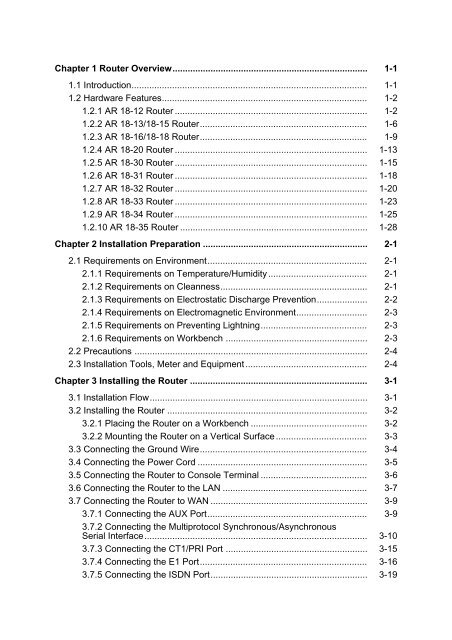
<strong>Installation</strong> <strong>Manual</strong><strong>Quidway</strong> <strong>AR</strong> <strong>18</strong> <strong>Series</strong> <strong>Routers</strong>Chapter 1 Router Overview1.2 Hardware Features1.2.1 <strong>AR</strong> <strong>18</strong>-12 RouterI. Appearance( 1(( 2(( 3(( 4(( 5(( 6(1) POWER LED 2) 100M ETH LED3) SERIAL0 LED 4) SERIAL1 LED5) AUX LED 6) SYSTEM LEDFigure 1-1 Front panel <strong>of</strong> <strong>AR</strong> <strong>18</strong>-12 RouterDC12VCONAUX100M ETH(1) (2) (3) (4) (5) (6) (7) (8)1) Power switch 2) Power input socket3) Console port (CON) 4) AUX port5) FE (Fast Ethernet) port (100M ETH) 6) Grounding screw7) Multiprotocol synchronous/asynchronousport0 (SERIAL0)Figure 1-2 Rear panel <strong>of</strong> <strong>AR</strong> <strong>18</strong>-12 Router8) Multiprotocol synchronous/asynchronous port 1(SERIAL1)1-2
<strong>Installation</strong> <strong>Manual</strong><strong>Quidway</strong> <strong>AR</strong> <strong>18</strong> <strong>Series</strong> <strong>Routers</strong>Chapter 1 Router OverviewII. System specificationsTable 1-1 System specifications <strong>of</strong> <strong>AR</strong> <strong>18</strong>-12 RouterItem <strong>AR</strong> <strong>18</strong>-121 console portPort1 10/100M Ethernet port1 AUX port2 multiprotocol synchronous/asynchronous serial interfacesProcessorSDRAMFlash memoryMaximum powerMPC860T 50MHz64MB8MB10 WPowersupply(external)InputOutputRated voltage:100-240V a.c.; 50/60HzMaximum tolerance:90-264V a.c.; 50/60HzCurrent: 1 to 0.5AVoltage: 12V d.c.Current: 4ADimensions (W X H X D)WeightOperating temperatureRelative humidity251mm X 42.5 mm X <strong>18</strong>7mm (Maximum dimensions, which are thehighest arc points <strong>of</strong> the plastic panel.)0.85kg0 to 40 0 C10 to 90% (noncondensing) Note:Router program operates in SDRAM (Synchronous Dynamic Random Access Memory).Flash memory is used to save Router program files, configuration files and so on.Boot ROM is used to save boot and initialization programs <strong>of</strong> the Router.III. LEDsViewing with the front panel forward, there are six LEDs on the cover <strong>of</strong> the router:POWER, 100M ETH, SERIAL0, SERIAL1, AUX, and SYSTEM. The following tableexplains their meaning:1-3
<strong>Installation</strong> <strong>Manual</strong><strong>Quidway</strong> <strong>AR</strong> <strong>18</strong> <strong>Series</strong> <strong>Routers</strong>Chapter 1 Router OverviewTable 1-2 LEDs <strong>of</strong> Quidwy <strong>AR</strong> <strong>18</strong>-12 RouterLEDDescriptionPOWER100M ETHOFF means that power is not being supplied.ON means that power is being supplied.Off means that the link is not connected.Blinking means that data is being sent or received over the Ethernet port.OFF means that the link is not connected.SERIAL0ON means that the link is connected.Blinking means that data is being sent or received over thesynchronous/asynchronous port 0.OFF means that the link is not connected.SERIAL1ON means that the link is connected.Blinking means that data is being sent or received over thesynchronous/asynchronous port 1.OFF means that the link is not connected.AUXON means that the link is connected.Blinking means that data is being sent or received over the AUX port.SYSTEMBlinking means that the system is properly working.Always ON or OFF means that the system is incorrectly working.IV. Port attributes<strong>AR</strong> <strong>18</strong>-12 Router provides console port, AUX port, 10/100M Ethernet port andmultiprotocol synchronous/asynchronous serial interface. Their port attributes aredescribed in the following tables.• Console portTable 1-3 Attributes <strong>of</strong> the console portAttributeDescriptionConnectorInterface standardBaud rateRJ45Asynchronous RS2329600 to 115200bpsDefaults to 9600bps1-4
<strong>Installation</strong> <strong>Manual</strong><strong>Quidway</strong> <strong>AR</strong> <strong>18</strong> <strong>Series</strong> <strong>Routers</strong>Chapter 1 Router OverviewAttributeDescriptionConnects with ASCII terminalServicesConnects with serial interfaces <strong>of</strong> the local PCs and runs the terminalemulation program on the PCsCommand line interface• AUX portTable 1-4 Attributes <strong>of</strong> the AUX portAttributeDescriptionConnectorInterface standardBaud rateServicesRJ45Asynchronous RS232300 to 115200bpsModem dial-upBackup• Ethernet portTable 1-5 Attributes <strong>of</strong> the Fast Ethernet portAttributeDescriptionConnectorOperating modeRJ4510/100Mbps autosensingFull duplex/half duplex• Multiprotocol synchronous/asynchronous serial interfaceTable 1-6 Attributes <strong>of</strong> multiprotocol synchronous/asynchronous serial interfaceAttributeSynchronousDescriptionAsynchronousConnectorInterfacestandardandoperatingmodeDB50V.24 (RS2322) V.35RS449, X.21 andRS530DTE, DCE DTE , DCE DTE DCEV.24 (RS-232)Minimumbaud rate(bps)1200 1200 1200 1200 3001-5
<strong>Installation</strong> <strong>Manual</strong><strong>Quidway</strong> <strong>AR</strong> <strong>18</strong> <strong>Series</strong> <strong>Routers</strong>Chapter 1 Router OverviewAttributeSynchronousDescriptionAsynchronousMaximumbaud rate(bps)64 k 4.096 M4.096M2.048M115.2 kServicesDDN leased lineTerminal accessBackupModem dial-upBackup1.2.2 <strong>AR</strong> <strong>18</strong>-13/<strong>18</strong>-15 RouterI. Appearance( 1(( 2(( 3(( 4(( 5(( 6(1) POWER LED 2) 100M ETH LED3) SERIAL LED 4) BRI LED5) AUX LED 6) SYSTEM LEDFigure 1-3 Front Panel <strong>of</strong> <strong>AR</strong> <strong>18</strong>-13/<strong>18</strong>-15 RouterOFF ON DC12VCONAUX100M ETHSERIALBRI(1) (2) (3) (4) (5) (6) (7) (8)1) Power switch 2) Power input socket3) Console port (CON) 4) AUX port5) FE port (100M ETH) 6) Multiprotocol synchronous/asynchronous port 0 (SERIAL0)7) Grounding screw 8) BRI portFigure 1-4 Rear panel <strong>of</strong> <strong>AR</strong> <strong>18</strong>-13/<strong>18</strong>-15 Router1-6
<strong>Installation</strong> <strong>Manual</strong><strong>Quidway</strong> <strong>AR</strong> <strong>18</strong> <strong>Series</strong> <strong>Routers</strong>Chapter 1 Router OverviewII. System specificationsTable 1-7 System specifications <strong>of</strong> <strong>AR</strong> <strong>18</strong>-13/<strong>18</strong>-15 RouterItem <strong>AR</strong> <strong>18</strong>-13 description <strong>AR</strong> <strong>18</strong>-15 descriptionPortProcessorSDRAMFlash memoryMaximum power1 console port1 10/100M Ethernet port1 AUX port1 multiprotocolsynchronous/asynchronous serialinterface1 ISDN BRI S/T portMPC860T 50MHz64 MB8 MB10 W1 console port1 10/100M Ethernet port1 AUX port1 multiprotocolsynchronous/asynchronous serialinterface1 ISDN BRI U portPowersupply(external)InputOutputRated voltage:100-240V a.c.; 50/60HzMaximum tolerance:90-264V a.c.; 50/60HzCurrent: 1 to 0.5AVoltage: 12V d.c.Current: 4ADimensions (W X H X D)WeightOperating temperatureOperating humidity251mm X 42.5 mm X <strong>18</strong>7mm (Maximum dimensions, which are thehighest arc points <strong>of</strong> the plastic panel.)0.85kg0 to 400C10 to 90% (noncondensing) Note:Router program operates in SDRAM (Synchronous Dynamic Random Access Memory).Flash memory is used to save Router program files, configuration files and so on.Boot ROM is used to save boot and initialization programs <strong>of</strong> the Router.1-7
<strong>Installation</strong> <strong>Manual</strong><strong>Quidway</strong> <strong>AR</strong> <strong>18</strong> <strong>Series</strong> <strong>Routers</strong>Chapter 1 Router OverviewIII. LEDsViewing with the front panel forward, there are six LEDs on the router cover: POWER,100M ETH, SERIAL, BRI, AUX, and SYSTEM. The following table explains theirmeanings:Table 1-8 LEDs <strong>of</strong> <strong>AR</strong> <strong>18</strong>-13/<strong>18</strong>-15 RouterLEDDescriptionPOWER100M ETHOFF means that power is not being supplied.ON means that power is being supplied.OFF means that the link is not connected.Blinking means that data is being sent or received over the Ethernetport.OFF means that the link is not connected.SERIALBRION means that the link is connected.Blinking means that data is being sent or received over thesynchronous/asynchronous port.OFF means that no data is being sent or received over the ISDN BRIport and two B channels are free.Blinking means that data is being sent and received over the ISDN BRIport.OFF means that the link is not connected.AUXON means that the link is connected.Blinking means that data is being sent or received over the AUX port.SYSTEMBlinking means that the system is properly working.Always ON or OFF means that the system is incorrectly working.IV. Port attributes<strong>AR</strong> <strong>18</strong>-13/<strong>18</strong>-15 Router provides console port, AUX port, 10/100M Ethernet port,multiprotocol synchronous/asynchronous serial interface, ISDN S/T or U port.Thefollowing tables describe the attributes <strong>of</strong> ISDN S/T port, U port. For the attributes <strong>of</strong>other ports, refer to Table1-3 through Table1-6 in “Section 1.2.1 <strong>AR</strong> <strong>18</strong>-12 <strong>Routers</strong>”.• ISDN S/T and U ports1-8
<strong>Installation</strong> <strong>Manual</strong><strong>Quidway</strong> <strong>AR</strong> <strong>18</strong> <strong>Series</strong> <strong>Routers</strong>Chapter 1 Router OverviewTable 1-9 Attributes <strong>of</strong> ISDN S/T and U portsAttributeDescriptionConnectorProtocol standardsOperating modeRJ45Complies with ITU-T I.430, Q.921 and Q.931 recommendationsISDN dial-upISDN leased lineISDNISDN additional servicesServices1) Multi-subscriber number2) SubaddressBackup1.2.3 <strong>AR</strong> <strong>18</strong>-16/<strong>18</strong>-<strong>18</strong> RouterI. Appearance(1)(2)(3)(4)(5)(6)1) POWER LED 2) ETH LED3) T1-LINK LED 4) T1-ACT LED5) AUX LED 6) SYSTEM LEDFigure 1-5 Front panel <strong>of</strong> <strong>AR</strong> <strong>18</strong>-16 Router1-9
<strong>Installation</strong> <strong>Manual</strong><strong>Quidway</strong> <strong>AR</strong> <strong>18</strong> <strong>Series</strong> <strong>Routers</strong>Chapter 1 Router OverviewDC12VCONAUX 100M ETHCT1/PRI(1) (2) (3) (4) (5) (6) (7)1) Power switch 2) Power input socket3) Console port (CON) 4) AUX port5) FE port (100M ETH) 6) Grounding screw7) CT1/PRI portFigure 1-6 Rear panel <strong>of</strong> <strong>AR</strong> <strong>18</strong>-16 Router1) POWER LED 2) 100M ETH LED(3) E1-LINK LED 4) E1-ACT LED5) AUX LED 6) SYSTEM LEDFigure 1-7 Front panel <strong>of</strong> <strong>AR</strong> <strong>18</strong>-<strong>18</strong> Router1) Power switch 2) Power input socket3) Console port (CON) 4) AUX port5) 100M ETH port 6) Grounding screw7) E1-F port 8) Port impedance toggling buttonFigure 1-8 Rear panel <strong>of</strong> <strong>AR</strong> <strong>18</strong>-<strong>18</strong> Router1-10
<strong>Installation</strong> <strong>Manual</strong><strong>Quidway</strong> <strong>AR</strong> <strong>18</strong> <strong>Series</strong> <strong>Routers</strong>Chapter 1 Router OverviewII. System specificationsTable 1-10 System specifications <strong>of</strong> <strong>AR</strong> <strong>18</strong>-16/<strong>18</strong>-<strong>18</strong> RouterItem <strong>AR</strong> <strong>18</strong>-16 description <strong>AR</strong> <strong>18</strong>-<strong>18</strong> descriptionPort1 console port1 10/100Mbps Ethernet port1 AUX port1 CT1/PRI port1 console port1 10/100Mbps Ethernet port1 AUX port1 E1-F portButton -1 E1-F port impedancetoggling buttonProcessorSDRAMFlash memoryMaximum powerMPC860T 50MHz64 MB8 MB10 WPowersupply(external)InputOutputRated voltage:100-240V a.c.; 50/60HzMaximum tolerance:90-264V a.c.; 50/60HzCurrent: 1 to 0.5AVoltage: 12V d.c.Current: 4ADimensions (W X H X D)WeightOperating temperatureOperating humidity251mm X 42.5 mm X <strong>18</strong>7mm (Maximum dimensions, which are thehighest arc points <strong>of</strong> the plastic panel.)0.85kg0 to 40 0 C10 to 90% (noncondensing) Note:Router program operates in SDRAM (Synchronous Dynamic Random Access Memory).Flash memory is used to save Router program files, configuration files and so on.Boot ROM is used to save boot and initialization programs <strong>of</strong> the Router.III. LEDsViewing with the front panel forward, there are six LEDs on <strong>AR</strong><strong>18</strong>-16/<strong>18</strong>-<strong>18</strong> cover:POWER, 100M ETH, T1-LINK (<strong>AR</strong> <strong>18</strong>-16)/E1-LINK (<strong>AR</strong> <strong>18</strong>-<strong>18</strong>), T1-ACT (<strong>AR</strong> <strong>18</strong>-1-11
<strong>Installation</strong> <strong>Manual</strong><strong>Quidway</strong> <strong>AR</strong> <strong>18</strong> <strong>Series</strong> <strong>Routers</strong>Chapter 1 Router Overview16)/E1-ACT (<strong>AR</strong> <strong>18</strong>-<strong>18</strong>), AUX, and SYSTEM, from top to bottom. The following tableexplains their meaning:Table 1-11 LEDs <strong>of</strong> <strong>AR</strong> <strong>18</strong>-16 RouterLEDDescriptionPOWER100M ETHT1-LINK/E1-LINKT1-ACT/E1-ACTOFF means that power is not being supplied.ON means that power is being supplied.OFF means that the link is not connected.Blinking means that data is being sent from or received by the Ethernetport.OFF means that link is not set up.ON means that link has been set up.OFF means that no data is being sent or received over the port.Blinking means that data is being sent and received over the port.OFF means that no data is being sent or received over the AUX port.AUXON means that the link is connected.Blinking means that data is being sent or received over the AUX port.SYSTEMBlinking means that the system is properly working.Always ON or OFF means that the system is incorrectly working.IV. Port attributes<strong>AR</strong> <strong>18</strong>-16/<strong>18</strong>-<strong>18</strong> <strong>Routers</strong> provide console port, AUX port, 10/100M Ethernet port, andCT1/PRI port (<strong>AR</strong> <strong>18</strong>-16) / E1-F (<strong>AR</strong> <strong>18</strong>-<strong>18</strong>).The following table describes theattributes <strong>of</strong> CT1/PRI port. For the attributes <strong>of</strong> other ports, refer to Table1-3 throughTable1-5 in “Section 1.2.1 <strong>AR</strong> <strong>18</strong>-12 <strong>Routers</strong>”.• CT1/PRI and E1-F portsTable 1-12 Attributes <strong>of</strong> CT1/PRI and E1-F portsAttribute CT1/PRI description E1 descriptionConnector RJ45 DB15Interface standard G.703. G.704Interface rate 1.544Mbps 2.048MbpsOperating modeCT1ISDN PRIE1CE11-12
<strong>Installation</strong> <strong>Manual</strong><strong>Quidway</strong> <strong>AR</strong> <strong>18</strong> <strong>Series</strong> <strong>Routers</strong>Chapter 1 Router OverviewAttribute CT1/PRI description E1 descriptionBackupServicesTerminal accessISDN1.2.4 <strong>AR</strong> <strong>18</strong>-20 RouterI. Appearance(1) ETH LED (LAN3) (2) ETH LED (LAN2)(3) ETH LED (LAN1) (4) ETH LED (LAN0)(5) WAN LED (WAN) (6) System LED (SYS)(7) Power LED (PWR)Figure 1-9 Front Panel <strong>of</strong> <strong>AR</strong> <strong>18</strong>-20 Router(1) Power switch (2) Power input socket(3) Console port (CON) (4) Ethernet port 0 (LAN0)(5) Ethernet port 1 (LAN1) (6) Ethernet port 2 (LAN2)(7) Ethernet port 3 (LAN3) (8) Grounding screw(9) WAN port (WAN)Figure 1-10 Rear panel <strong>of</strong> <strong>AR</strong> <strong>18</strong>-20 Router1-13
<strong>Installation</strong> <strong>Manual</strong><strong>Quidway</strong> <strong>AR</strong> <strong>18</strong> <strong>Series</strong> <strong>Routers</strong>Chapter 1 Router OverviewII. System specificationsTable 1-13 System specifications <strong>of</strong> <strong>AR</strong> <strong>18</strong>-20 RouterItem<strong>AR</strong> <strong>18</strong>-20 description1 console portPort1 10M Ethernet port (WAN)Four 10/100M Ethernet port (LAN)ProcessorSDRAMFlash memoryMaximum powerconsumptionMPC85964MB8MB10WPowersupply(external)InputOutputRated voltage: 100-240V a.c., 50/60HzMaximum tolerance: 90-264V a.c. , 50/60HzCurrent: 0.5A~1AVoltage: 12V d.c.Current: 4ADimensions (W X H X D)WeightOperating temperatureOperating humidity300mm X <strong>18</strong>0mm X 45mm (Maximum dimensions, which are thehighest arc points <strong>of</strong> the plastic panel.)1kg0 to 40 0 C10 to 90% (noncondensing)III. LEDsThere are seven LEDs on <strong>AR</strong><strong>18</strong>-20 cover. The following table explains their meaning.Table 1-14 LEDs <strong>of</strong> <strong>AR</strong> <strong>18</strong>-20 RouterLEDLAN0/LAN1/LAN2/LAN3/WANSYSDescriptionOFF means that link is not set up.ON means that link has been set up.Blinking means that data is being sent from or received at the port.Blinking means that the system is properly working.Always ON or OFF means that the system is incorrectly working.1-14
<strong>Installation</strong> <strong>Manual</strong><strong>Quidway</strong> <strong>AR</strong> <strong>18</strong> <strong>Series</strong> <strong>Routers</strong>Chapter 1 Router OverviewPWRLEDDescriptionOFF means that power is not being supplied.ON means that power is being supplied.IV. Port attributes<strong>AR</strong> <strong>18</strong>-20 Router provides console port, 10M and 10/100M Ethernet port. Thefollowing table describes the attributes <strong>of</strong> 10M and 10/100M Ethernet port.• Ethernet portTable 1-15 Attributes <strong>of</strong> Ethernet portAttribute 10BASE-T 10/100BASE-TConnectorRJ45Operating mode10MbpsFull duplex/half duplex10/100Mbps auto-sensingMDI/MDIX auto-sensingFull duplex/half duplexOnly L2 switching available1.2.5 <strong>AR</strong> <strong>18</strong>-30 RouterI. Appearance(1) ETH LED (LAN3) (2) ETH LED (LAN2)(3) ETH LED (LAN1) (4) ETH LED (LAN0)(5) ADSL active LED (DSL ACT) (6) ADSL link LED (DSL LNK)(7) System LED (SYS) (8) Power LED (PWR)Figure 1-11 Front panel <strong>of</strong> <strong>AR</strong> <strong>18</strong>-30 Router1-15
<strong>Installation</strong> <strong>Manual</strong><strong>Quidway</strong> <strong>AR</strong> <strong>18</strong> <strong>Series</strong> <strong>Routers</strong>Chapter 1 Router Overview(1) Power switch (2) Power input socket(3) Console port (CON) (4) Ethernet port 0 (LAN0)(5) Ethernet port 1 (LAN1) (6) Ethernet port 2 (LAN2)(7) Ethernet port 3 (LAN3) (8) Grounding screw(9) ADSL port (ADSL over POTS)Figure 1-12 Rear panel <strong>of</strong> <strong>AR</strong> <strong>18</strong>-30 RouterII. System specificationsTable 1-16 System specifications <strong>of</strong> <strong>AR</strong> <strong>18</strong>-30 RouterItem<strong>AR</strong> <strong>18</strong>-30 description1 console portPort1 ADSL over POTSFour 10/100M Ethernet port (LAN)ProcessorSDRAMFlash memoryMaximum powerconsumptionMPC85964MB8MB10WPowersupply(external)InputOutputRated voltage: 100-240V a.c., 50/60HzMaximum tolerance: 90-264V a.c., 50/60HzCurrent: 0.5A~1AVoltage: 12V d.c.Current: 4ADimensions (W X H XD)WeightOperating temperatureOperating humidity300mm X <strong>18</strong>0mm X 45mm (Maximum dimensions, which are the highestarc points <strong>of</strong> the plastic panel.)1kg0 to 40 0 C10 to 90% (noncondensing)1-16
<strong>Installation</strong> <strong>Manual</strong><strong>Quidway</strong> <strong>AR</strong> <strong>18</strong> <strong>Series</strong> <strong>Routers</strong>Chapter 1 Router OverviewIII. LEDsThere are eight LEDs on <strong>AR</strong><strong>18</strong>-20 cover. The following table explains their meaning.Table 1-17 LEDs <strong>of</strong> <strong>AR</strong> <strong>18</strong>-30 RouterLEDDescriptionOFF means that link is not set up.LAN0/LAN1/LAN2/LAN3ON means that link has been set up.Blinking means that data is being sent from or received at the interface.ADSL ACTOFF means that no data is being sent from or received at the interface.Blinking means that data is being sent from or received at the interface.ADSL LNKOFF means ADSL is inactive.ON means ADSL is active.Blinking means the interface is being trained.SYSBlinking means that the system is properly working.Always ON or OFF means that the system is incorrectly working.PWROFF means that power is not being supplied.ON means that power is being supplied.IV. Port attributes<strong>AR</strong> <strong>18</strong>-30 Router provides console port, 10/100M Ethernet port and ADSL over POTSport. The following table describes the attributes <strong>of</strong> ADSL over POTS port.• ADSL over POTS portTable 1-<strong>18</strong> Attributes <strong>of</strong> ADSL over POTS portAttributedescriptionConnectorRateRJ11ADSL full-rate mode (i.e. ITU-T 992.1 G.DMT/ANSI T1.413)12Mbps in downstream and 1024 kbps in upstreamADSL Lite mode ((ITU-T 992.2 G.Lite):In downstream, 64 kbps~1.5Mbps in steps <strong>of</strong> 32 kbps; in upstream,64 kbps~512 kbps in steps <strong>of</strong> 32 kbps1-17
<strong>Installation</strong> <strong>Manual</strong><strong>Quidway</strong> <strong>AR</strong> <strong>18</strong> <strong>Series</strong> <strong>Routers</strong>Chapter 1 Router OverviewAttributedescriptionITU-T 992.1 G.DMTInterface standardITU-T 992.2 G.LiteITU-T 994.1 handshakingANSI T1.413 Issue 2ServicesADSL access over twisted pairs1.2.6 <strong>AR</strong> <strong>18</strong>-31 RouterI. Appearance(1) ETH LED (LAN3) (2) ETH LED (LAN2)(3) ETH LED (LAN1) (4) ETH LED (LAN0)(5) ADSL active LED (DSL ACT) (6) ADSL LINK LED (DSL LINK)(7) ISDN B2 active LED (ISDN B2 ACT) (8) ISDN B1 active LED (ISDN B1 ACT)(9) ISDN link LED (ISDN LNK) (10) System LED (SYS)(11) Power LED (PWR)Figure 1-13 Front panel <strong>of</strong> <strong>AR</strong> <strong>18</strong>-31 Router(1) Power switch (2) Power input socket(3) Console port (CON) (4) Ethernet port 0 (LAN0)(5) Ethernet port 1 (LAN1) (6) Ethernet port 2 (LAN2)(7) Ethernet port 3 (LAN3) (8) Grounding screw(9) ISDN BRI port (10) ADSL over POTS portFigure 1-14 Rear panel <strong>of</strong> <strong>AR</strong> <strong>18</strong>-31 Router1-<strong>18</strong>
<strong>Installation</strong> <strong>Manual</strong><strong>Quidway</strong> <strong>AR</strong> <strong>18</strong> <strong>Series</strong> <strong>Routers</strong>Chapter 1 Router OverviewII. System specificationsTable 1-19 System specifications <strong>of</strong> <strong>AR</strong> <strong>18</strong>-31 RouterItem<strong>AR</strong> <strong>18</strong>-31 description1 console portPort1 ADSL over POTS1 ISDN BRI S/T portFour 10/100M Ethernet portsProcessorSDRAMFlash memoryMaximum powerconsumptionMPC85964MB8MB10WPowersupply(external)InputOutputRated voltage: 100-240V a.c., 50/60HzMaximum tolerance: 90-264V a.c., 50/60HzCurrent: 0.5A~1AVoltage: 12V d.c.Current: 4ADimensions (W X HX D)WeightOperatingtemperatureOperating humidity300mm X <strong>18</strong>0mm X 45mm (Maximum dimensions, which are the highest arcpoints <strong>of</strong> the plastic panel.)1kg0 to 40 0 C10 to 90% (noncondensing)III. LEDsThere are eleven LEDs on <strong>AR</strong><strong>18</strong>-31 cover. The following table explains their meaning.Table 1-20 LEDs <strong>of</strong> <strong>AR</strong> <strong>18</strong>-31 RouterLEDDescriptionOFF means that link is not set up.LAN0/LAN1/LAN2/LAN3ON means that link has been set up.Blinking means that data is being sent from or received at the interface.1-19
<strong>Installation</strong> <strong>Manual</strong><strong>Quidway</strong> <strong>AR</strong> <strong>18</strong> <strong>Series</strong> <strong>Routers</strong>Chapter 1 Router OverviewLEDDescriptionDSL ACTOFF means that no data is being sent from or received at the interface.Blinking means that data is being sent from or received at the interface.DSL LNKOFF means ADSL is inactive.ON means ADSL is active.Blinking means the interface is being trained.ISDN B1 ACT/ ISDN B2ACTISDN LNKOFF means B1 or B2 is inactive.Blinking means B1 or B2 is active.OFF means ISDN is inactive.ON means ISDN is active.SYSBlinking means that the system is properly working.Always ON or OFF means that the system is incorrectly workingPWROFF means that power is not being supplied.ON means that power is being supplied.IV. Port attributes<strong>AR</strong> <strong>18</strong>-31 Router provides console port, 10/100M Ethernet port, ISDN S/T port andADSL over POTS port.1.2.7 <strong>AR</strong> <strong>18</strong>-32 RouterI. Appearance(1) ETH LED (LAN3) (2) ETH LED (LAN2)(3) ETH LED (LAN1) (4) ETH LED (LAN0)(5) ADSL active LED (DSL ACT) (6) ADSL LINK LED (DSL LINK)(7) System LED (SYS) (8) Power LED (PWR)Figure 1-15 Front panel <strong>of</strong> <strong>AR</strong> <strong>18</strong>-32 Router1-20
<strong>Installation</strong> <strong>Manual</strong><strong>Quidway</strong> <strong>AR</strong> <strong>18</strong> <strong>Series</strong> <strong>Routers</strong>Chapter 1 Router Overview(1) Power switch (2) Power input socket(3) Console port (CON) (4) Ethernet port 0 (LAN0)(5) Ethernet port 1 (LAN1) (6) Ethernet port 2 (LAN2)(7) Ethernet port 3 (LAN3) (8) Grounding screw(9) ADSL port (ADSL over ISDN)Figure 1-16 Rear panel <strong>of</strong> <strong>AR</strong> <strong>18</strong>-32 RouterII. System specificationsTable 1-21 System specifications <strong>of</strong> <strong>AR</strong> <strong>18</strong>-32 RouterItem<strong>AR</strong> <strong>18</strong>-32 description1 console portPort1 ADSL over ISDNFour 10/100M Ethernet portsProcessorSDRAMFlash memoryMaximum powerconsumptionMPC85964MB8MB10WPowersupply(external)InputOutputRated voltage: 100-240V a.c., 50/60HzMaximum tolerance: 90-264V a.c., 50/60HzCurrent: 0.5A~1AVoltage: 12V d.c.Current: 4ADimensions (W X HX D)WeightOperatingtemperatureOperating humidity300mm X <strong>18</strong>0mm X 45mm (Maximum dimensions, which are the highest arcpoints <strong>of</strong> the plastic panel.)1kg0 to 40 0 C10 to 90% (noncondensing)1-21
<strong>Installation</strong> <strong>Manual</strong><strong>Quidway</strong> <strong>AR</strong> <strong>18</strong> <strong>Series</strong> <strong>Routers</strong>Chapter 1 Router OverviewIII. LEDsThere are eight LEDs on <strong>AR</strong><strong>18</strong>-31 cover. The following table explains their meaning.Table 1-22 LEDs <strong>of</strong> <strong>AR</strong> <strong>18</strong>-32 RouterLEDDescriptionOFF means that link is not set up.LAN0/LAN1/LAN2/LAN3ON means that link has been set up.Blinking means that data is being sent from or received at the interface.DSL ACTOFF means that no data is being sent from or received at the interface.Blinking means that data is being sent from or received at the interface.DSL LNKOFF means ADSL is inactive.ON means ADSL is active.Blinking means the interface is being trained.SYSBlinking means that the system is properly working.Always ON or OFF means that the system is incorrectly workingPWROFF means that power is not being supplied.ON means that power is being supplied.IV. Port attributes<strong>AR</strong> <strong>18</strong>-32 Router provides console port, 10/100M Ethernet port and ADSL over ISDNport. The following table describes the attributes <strong>of</strong> ADSL over ISDN port.• ADSL over ISDN portTable 1-23 Attributes <strong>of</strong> ADSL over ISDN portAttributedescriptionConnectorRateRJ11ADSL full-rate mode (i.e. ITU-T 992.1 G.DMT/ANSI T1.413)8Mbps in downstream and 1024 kbps in upstreamITU-T 992.1 G.DMTInterface standardITU-T 994.1 handshakingANSI T1.413 Issue 2ServicesADSL access over ISDN line1-22
<strong>Installation</strong> <strong>Manual</strong><strong>Quidway</strong> <strong>AR</strong> <strong>18</strong> <strong>Series</strong> <strong>Routers</strong>Chapter 1 Router Overview1.2.8 <strong>AR</strong> <strong>18</strong>-33 RouterI. Appearance(1) ETH LED (LAN3) (2) ETH LED (LAN2)(3) ETH LED (LAN1) (4) ETH LED (LAN0)(5) SHDSL active LED (DSL ACT) (6) SHDSL link LED (DSL LNK)(7) System LED (SYS) (8) Power LED (PWR)Figure 1-17 Front panel <strong>of</strong> <strong>AR</strong> <strong>18</strong>-33 Router(1) Power switch (2) Power input socket(3) Console port (CON) (4) Ethernet port 0 (LAN0)(5) Ethernet port 1 (LAN1) (6) Ethernet port 2 (LAN2)(7) Ethernet port 3 (LAN3) (8) Grounding screw(9) G.SHDSL portFigure 1-<strong>18</strong> Rear panel <strong>of</strong> <strong>AR</strong> <strong>18</strong>-33 RouterII. System specificationsTable 1-24 System specifications <strong>of</strong> <strong>AR</strong> <strong>18</strong>-33 RouterItem<strong>AR</strong> <strong>18</strong>-33 description1 console portPort1 G.SHDSL portFour 10/100M Ethernet portsProcessorMPC8591-23
<strong>Installation</strong> <strong>Manual</strong><strong>Quidway</strong> <strong>AR</strong> <strong>18</strong> <strong>Series</strong> <strong>Routers</strong>Chapter 1 Router OverviewItem<strong>AR</strong> <strong>18</strong>-33 descriptionSDRAMFlash memoryMaximum powerconsumption64MB8MB10WPowersupply(external)InputOutputRated voltage: 100-240V a.c., 50/60HzMaximum tolerance: 90-264V a.c., 50/60HzCurrent: 0.5A~1AVoltage: 12V d.c.Current: 4ADimensions (W X HX D)WeightOperatingtemperatureOperating humidity300mm X <strong>18</strong>0mm X 45mm (Maximum dimensions, which are the highest arcpoints <strong>of</strong> the plastic panel.)1kg0 to 40 0 C10 to 90% (noncondensing)III. LEDsThere are eight LEDs on <strong>AR</strong><strong>18</strong>-33 cover. The following table explains their meaning.Table 1-25 LEDs <strong>of</strong> <strong>AR</strong> <strong>18</strong>-33 RouterLEDDescriptionOFF means that link is not set up.LAN0/LAN1/LAN2/LAN3ON means that link has been set up.Blinking means that data is being sent from or received at the interface.DSL ACTOFF means that no data is being sent from or received at the interface.Blinking means that data is being sent from or received at the interface.DSL LNKOFF means G.SHDSL is inactive.ON means G.SHDSL is active.Blinking means the interface is being trained.SYSBlinking means that the system is properly working.Always ON or OFF means that the system is incorrectly workingPWROFF means that power is not being supplied.ON means that power is being supplied.1-24
<strong>Installation</strong> <strong>Manual</strong><strong>Quidway</strong> <strong>AR</strong> <strong>18</strong> <strong>Series</strong> <strong>Routers</strong>Chapter 1 Router OverviewIV. Port attributes<strong>AR</strong> <strong>18</strong>-31 Router provides console port, 10/100M Ethernet port, ISDN S/T port andG.SHDSL port. The following table describes the attributes <strong>of</strong> G.SHDSL port.• G.SHDSL portTable 1-26 Attributes <strong>of</strong> G.SHDSL portAttributedescriptionConnectorRateRJ11In single-pair mode, it transceives packets at symmetric rate192 kbps~2320 kbps, in steps <strong>of</strong> 8 kbps.Interface standardServicesITU-T G991.2ITU-T G994.1 handshakingG.SHDSL access over twisted pairs1.2.9 <strong>AR</strong> <strong>18</strong>-34 RouterI. Appearance(1) ETH LED (LAN3) (2) ETH LED (LAN2)(3) ETH LED (LAN1) (4) ETH LED (LAN0)(5) SHDSL active LED (DSL ACT) (6) SHDSL link LED (DSL LNK)(7) ISDN B2 active LED (ISDN B2 ACT) (8) ISDN B1 active LED (ISDN B1 ACT)(9) ISDN link LED (ISDN LNK) (10) System LED (SYS)(12) Power LED (PWR)Figure 1-19 Front panel <strong>of</strong> <strong>AR</strong> <strong>18</strong>-34 Router1-25
<strong>Installation</strong> <strong>Manual</strong><strong>Quidway</strong> <strong>AR</strong> <strong>18</strong> <strong>Series</strong> <strong>Routers</strong>Chapter 1 Router Overview(1) Power switch (2) Power input socket(3) Console port (CON) (4) Ethernet port 0 (LAN0)(5) Ethernet port 1 (LAN1) (6) Ethernet port 2 (LAN2)(7) Ethernet port 3 (LAN3) (8) Grounding screw(9) ISDN BRI port (10) G.SHDSL portFigure 1-20 Rear panel <strong>of</strong> <strong>AR</strong> <strong>18</strong>-34 RouterII. System specificationsTable 1-27 System specifications <strong>of</strong> <strong>AR</strong> <strong>18</strong>-34 Router <strong>AR</strong> <strong>18</strong>-34Item<strong>AR</strong> <strong>18</strong>-34 description1 console portPort1 G.SHDSL port1 ISDN BRI S/T portFour 10/100M Ethernet portsProcessorSDRAMFlash memoryMaximum powerconsumptionMPC85964MB8MB10WPowersupply(external)InputOutputRated voltage: 100-240V a.c., 50/60HzMaximum tolerance: 90-264V a.c., 50/60HzCurrent: 0.5A~1AVoltage: 12V d.c.Current: 4ADimensions (W X H XD)WeightOperating temperatureOperating humidity300mm X <strong>18</strong>0mm X 45mm (Maximum dimensions, which are the highestarc points <strong>of</strong> the plastic panel.)1kg0 to 40 0 C10 to 90% (noncondensing)1-26
<strong>Installation</strong> <strong>Manual</strong><strong>Quidway</strong> <strong>AR</strong> <strong>18</strong> <strong>Series</strong> <strong>Routers</strong>Chapter 1 Router OverviewIII. LEDsThere are eleven LEDs on <strong>AR</strong><strong>18</strong>-34 cover. The following table explains their meaning.Table 1-28 LEDs <strong>of</strong> <strong>AR</strong> <strong>18</strong>-34 RouterLEDDescriptionOFF means that link is not set up.LAN0/LAN1/LAN2/LAN3ON means that link has been set up.Blinking means that data is being sent from or received at the interface.DSL ACTOFF means that no data is being sent from or received at the interface.Blinking means that data is being sent from or received at the interface.DSL LNKOFF means ADSL is inactive.ON means ADSL is active.Blinking means the interface is being trained.ISDN B1 ACT/ ISDN B2ACTISDN LNKOFF means B1 or B2 is inactive.Blinking means B1 or B2 is active.OFF means ISDN is inactive.ON means ISDN is active.SYSBlinking means that the system is properly working.Always ON or OFF means that the system is incorrectly workingPWROFF means that power is not being supplied.ON means that power is being supplied.IV. Port attributes<strong>Quidway</strong> <strong>AR</strong> <strong>18</strong>-34 Router provides console port, 10/100M Ethernet port, ISDN S/Tport and G.SHDSL port.1-27
<strong>Installation</strong> <strong>Manual</strong><strong>Quidway</strong> <strong>AR</strong> <strong>18</strong> <strong>Series</strong> <strong>Routers</strong>Chapter 1 Router Overview1.2.10 <strong>AR</strong> <strong>18</strong>-35 RouterI. Appearance(1) ETH LED (LAN3) (2) ETH LED (LAN2)(3) ETH LED (LAN1) (4) ETH LED (LAN0)(5) ADSL active LED (DSL ACT) (6) ADSL LINK LED (DSL LINK)(7) ISDN B2 active LED (ISDN B2 ACT) (8) ISDN B1 active LED (ISDN B1 ACT)(9) ISDN link LED (ISDN LNK) (10) System LED (SYS)(11) Power LED (PWR)Figure 1-21 Front panel <strong>of</strong> <strong>AR</strong> <strong>18</strong>-35 Router(1) Power switch (2) Power input socket(3) Console port (CON) (4) Ethernet port 0 (LAN0)(5) Ethernet port 1 (LAN1) (6) Ethernet port 2 (LAN2)(7) Ethernet port 3 (LAN3) (8) Grounding screw(9) ISDN BRI port (10) ADSL over ISDN portFigure 1-22 Rear panel <strong>of</strong> <strong>AR</strong> <strong>18</strong>-35 Router1-28
<strong>Installation</strong> <strong>Manual</strong><strong>Quidway</strong> <strong>AR</strong> <strong>18</strong> <strong>Series</strong> <strong>Routers</strong>Chapter 1 Router OverviewII. System specificationsTable 1-29 System specifications <strong>of</strong> <strong>AR</strong> <strong>18</strong>-35 RouterItem<strong>AR</strong> <strong>18</strong>-35 description1 console portPort1 ADSL over ISDN1 ISDN BRI S/T portFour 10/100M Ethernet portsProcessorSDRAMFlash memoryMaximum powerconsumptionMPC85964MB8MB10WPowersupply(external)InputOutputRated voltage: 100-240V a.c., 50/60HzMaximum tolerance: 90-264V a.c., 50/60HzCurrent: 0.5A~1AVoltage: 12V d.c.Current: 4ADimensions (W X HX D)WeightOperatingtemperatureOperating humidity300mm X <strong>18</strong>0mm X 45mm (Maximum dimensions, which are the highest arcpoints <strong>of</strong> the plastic panel.)1kg0 to 40 0 C10 to 90% (noncondensing)III. LEDsThere are eleven LEDs on <strong>AR</strong><strong>18</strong>-35 cover. The following table explains their meaning.Table 1-30 LEDs <strong>of</strong> <strong>AR</strong> <strong>18</strong>-35 RouterLEDDescriptionOFF means that link is not set up.LAN0/LAN1/LAN2/LAN3ON means that link has been set up.Blinking means that data is being sent from or received at the interface.1-29
<strong>Installation</strong> <strong>Manual</strong><strong>Quidway</strong> <strong>AR</strong> <strong>18</strong> <strong>Series</strong> <strong>Routers</strong>Chapter 1 Router OverviewLEDDescriptionDSL ACTOFF means that no data is being sent from or received at the interface.Blinking means that data is being sent from or received at the interface.DSL LNKOFF means ADSL is inactive.ON means ADSL is active.Blinking means the interface is being trained.ISDN B1 ACT/ ISDN B2ACTISDN LNKOFF means B1 or B2 is inactive.Blinking means B1 or B2 is active.OFF means ISDN is inactive.ON means ISDN is active.SYSBlinking means that the system is properly working.Always ON or OFF means that the system is incorrectly workingPWROFF means that power is not being supplied.ON means that power is being supplied.IV. Port attributes<strong>AR</strong> <strong>18</strong>-35 Router provides console port, 10/100M Ethernet port, ISDN S/T port andADSL over ISDN port.1-30
<strong>Installation</strong> <strong>Manual</strong><strong>Quidway</strong> <strong>AR</strong> <strong>18</strong> <strong>Series</strong> <strong>Routers</strong>Chapter 2 <strong>Installation</strong> PreparationChapter 2 <strong>Installation</strong> Preparation2.1 Requirements on Environment<strong>AR</strong> <strong>18</strong> series must be used indoors. To ensure the normal operation and prolong theirservice life, the following requirements for installation site must be met.2.1.1 Requirements on Temperature/HumidityCertain requirements on temperature and humidity in the equipment room shall bemet. If the relative humidity is too high, the insulation materials in it will deteriorateeasily or even lead to electric leakage. Sometimes this will result in change to themechanical performance <strong>of</strong> the materials and rusting <strong>of</strong> the metal components. If therelative humidity is too low, the fastening screw will become loosen due to shrinkage<strong>of</strong> the isolation spacer. In an environment with dry climate, the static electricity may beproduced, putting the CMOS <strong>of</strong> the router to risk. High temperature is <strong>of</strong> the greatestrisk: for it will significantly degrade the router’s reliability, speed up the aging process<strong>of</strong> the insulating materials, and shorten the service life <strong>of</strong> the router. The requirementson the temperature and humidity for <strong>AR</strong> <strong>18</strong> series are shown in Table 2-1:Table 2-1 Humidity requirements in the equipment roomTemperatureRelative humidity0 o C to 40 o C 10% to 90%2.1.2 Requirements on CleannessDust undermines the normal operation <strong>of</strong> <strong>AR</strong> <strong>18</strong> series. Dust dropping on theequipment can cause electrostatic adsorption, which degrades the contactperformance <strong>of</strong> the metal connectors or connection points. This happens morefrequently when the indoor relative humidity is low, which will not only shorten therouter’s service life, but also cause communication failure.The recommended specification on dust content and particle diameter in theequipment room is shown in Table 2-2:2-1
<strong>Installation</strong> <strong>Manual</strong><strong>Quidway</strong> <strong>AR</strong> <strong>18</strong> <strong>Series</strong> <strong>Routers</strong>Chapter 2 <strong>Installation</strong> PreparationTable 2-2 Specifications on dust content in equipment roomMaxim diameter (µm) Max. intensity (particles/m 3 )0.5 1.4 x 10 71 7 x 10 53 2.4 x 10 55 1.3 x 10 5The routers also have rigorous demand on the content <strong>of</strong> salts, acids and sulfides inthe air. These harmful gases will speed up the metal rusting and the aging processes<strong>of</strong> certain parts. The equipment room should be protected from the invasion <strong>of</strong>harmful gases such as SO 2 , H 2 S, NO 2 , NH 3 , and Cl 2 , the value limits <strong>of</strong> which areshown in Table 2-3:Table 2-3 Value limits for harmful gas content in equipment roomGas Average (mg/m 3 ) Max. (mg/m 3 )SO2 0.2 1.5H2S 0 0.03NO2 0.04 0.15NH3 0.05 0.15Cl2 0.01 0.32.1.3 Requirements on Electrostatic Discharge PreventionAlthough many antistatic considerations have been given to <strong>AR</strong> <strong>18</strong> series, damage tothe router’s circuit or even the whole equipment may still happen when the staticelectricity exceeds the tolerance threshold.In the communication network to which the routers are connected, static inductionmainly comes from:• External electric fields such as outdoor high voltage power line or thunder.• Internal environment like flooring materials or the whole equipment structure.Thus, the following should be considered to safeguard the equipment against theESD:• Make sure that the equipment and the floor are well grounded.• Make sure that dust-pro<strong>of</strong> measures are taken.• Maintain an appropriate humidity and temperature.2-2
<strong>Installation</strong> <strong>Manual</strong><strong>Quidway</strong> <strong>AR</strong> <strong>18</strong> <strong>Series</strong> <strong>Routers</strong>Chapter 2 <strong>Installation</strong> Preparation• Wear an ESD-preventive wrist strap and uniform when contacting the circuitboard.• Place the uninstalled circuit board on the antistatic workbench, with its faceupward, or put it into the static shielding bag.• When observing or removing the uninstalled circuit board, please touch the edge<strong>of</strong> the circuit board, and avoid contacting the devices on it.2.1.4 Requirements on Electromagnetic EnvironmentThe interference sources, no matter where they come from, affect the routers withcapacitance coupling, inductance coupling, radiation <strong>of</strong> electromagnetic wave,common impedance (including the grounding system) or conducting line (power line,signal line and transmission line etc.).So the following should be considered:• Take effective measures to prevent the power system from being interfered withby the power grid system.• Keep the router far away from the radio launcher, radar launcher, and highfrequencydevices working in high currents.• Use electromagnetic shielding when necessary.2.1.5 Requirements on Preventing LightningAlthough many measures have been taken to protect <strong>AR</strong> <strong>18</strong> series from lightning, ifthe lightning intensity exceeds a certain range, damage to the router may still happen.To protect the router from lightning better, the following should be considered:• Ensure the PGND wire <strong>of</strong> the chassis is well grounded.• Ensure the ground point <strong>of</strong> the socket <strong>of</strong> AC power supply is well grounded.• To enhance the lightning protection capability <strong>of</strong> the power supply, a lightningarrester could be installed at the input end <strong>of</strong> the power supply.• As for the signal line outdoors to which the interface modules <strong>of</strong> <strong>AR</strong> <strong>18</strong> seriesrouters are connected, such as ISDN line, telephone line, T1 line, etc, a speciallightning arrester should be installed at the input end <strong>of</strong> the signal line toenhance the lightning protection capability.2.1.6 Requirements on Workbench• There is spacing reserved at the air inlet and outlet in the router so as to facilitatethe radiation <strong>of</strong> the router cabinet.• The workbench have good radiation systems.• The workbench are firm enough to support the weight <strong>of</strong> the router and otherinstallation accessories.• The workbench are well grounded.2-3
<strong>Installation</strong> <strong>Manual</strong><strong>Quidway</strong> <strong>AR</strong> <strong>18</strong> <strong>Series</strong> <strong>Routers</strong>Chapter 2 <strong>Installation</strong> Preparation2.2 Precautions<strong>Routers</strong> play a key role in data communications network. Please pay attention to thefollowing:Warning:It indicates that this operation is incorrect and may seriously damage the router or endanger the operator.Please follow the correct operation procedures for sake <strong>of</strong> safety.Caution:It indicates that during the installation and usage <strong>of</strong> the router, the operation needs attention. Thisoperation is incorrect and perhaps will affect the normal operation <strong>of</strong> the router.Please follow the following safety recommendations during the installation and use <strong>of</strong>the router:• Keep the router away from any wet place or the heat source.• Make sure that the router is normally grounded.• Please wear an ESD-preventive wrist strap before installation, and make sureone end <strong>of</strong> it well contacts your skin, and the other end is well grounded.• Do not hot swap any cable.• Correctly connect the interface cable for the router. Do not connect the telephonecable (including the ISDN cable) to the AUX port or the console port.• Always use Uninterrupted Power Supply (UPS).2.3 <strong>Installation</strong> Tools, Meter and EquipmentI. tools• ESD-preventive wrist strapII. Cables• Ground wire , power supply and power cord• Console cable• T1 cable (only used for Qudway <strong>AR</strong> <strong>18</strong>-16 Router)• ISDN S/T cable (for <strong>Quidway</strong> <strong>AR</strong> <strong>18</strong>-13//<strong>18</strong>-31/<strong>18</strong>-32/<strong>18</strong>-34/<strong>18</strong>-35 Router)2-4
<strong>Installation</strong> <strong>Manual</strong><strong>Quidway</strong> <strong>AR</strong> <strong>18</strong> <strong>Series</strong> <strong>Routers</strong>Chapter 2 <strong>Installation</strong> Preparation• ISDN U cable (only used for <strong>Quidway</strong> <strong>AR</strong> <strong>18</strong>-15 Router)• 75-ohm E1 cable and 120-ohm E1 cable (only for <strong>AR</strong> <strong>18</strong>-<strong>18</strong> Router)• Telephone cable(for <strong>AR</strong> <strong>18</strong>-30 series)• Synchronous/Asynchronous serial cable (optional)• Ethernet cable(optional)• AUX cable(optional)III. equipment and meter• HUB or LANSwitch• CSU/DSU (Channel Service Unit/Data Service Unit) or other DCE devices• Console terminal (it could just be a PC)• Multimeter• SpliterCaution:The installation tools , equipment and meter are not delivered with <strong>Quidway</strong> <strong>Quidway</strong> <strong>AR</strong> <strong>18</strong> <strong>Series</strong><strong>Routers</strong>.2-5
<strong>Installation</strong> <strong>Manual</strong><strong>Quidway</strong> <strong>AR</strong> <strong>18</strong> <strong>Series</strong> <strong>Routers</strong>Chapter 3 Installing the RouterChapter 3 Installing the Router3.1 <strong>Installation</strong> FlowStartInstall the router to thespecified positionConnect PGNDConnect power cordConnect console terminalCheck prior to power-onTurn on power switchNormal ?yesTurn <strong>of</strong>f power switchnoTroubleshootingConnect the router to LANConnect the router toWANVerifyTurn on power switchEndFigure 3-1 <strong>Installation</strong> procedrues for <strong>AR</strong> <strong>18</strong>-1x3-1
<strong>Installation</strong> <strong>Manual</strong><strong>Quidway</strong> <strong>AR</strong> <strong>18</strong> <strong>Series</strong> <strong>Routers</strong>Chapter 3 Installing the RouterStartInstall the ruter to thespecified positionConnect PGNDConnect console terminalConnect the router to WANConnect the router to LANConnect phone and PBXConnect pow er cordNormal?EndyesnoTroubleshootingFigure 3-2 <strong>Installation</strong> procedrues for <strong>AR</strong> <strong>18</strong>-2x/<strong>18</strong>-3x Note:<strong>AR</strong> <strong>18</strong>-2x/<strong>18</strong>-3x routers have no power switch, so their installation procedures are different from thosefor <strong>AR</strong><strong>18</strong>-1x routers.3.2 Installing the RouterThere are two ways to install <strong>Quidway</strong> <strong>AR</strong> <strong>18</strong> <strong>Series</strong> <strong>Routers</strong>:• Placing the router on the workbench.• Mounting the router on a vertical surface.3.2.1 Placing the Router on a WorkbenchIn this case, simply put the router on a clean and flat workbench. Please pay attentionto the following items:• Make sure that the workbench is flat and stable.• Leave 10cm space around the router for adequate ventilation.3-2
<strong>Installation</strong> <strong>Manual</strong><strong>Quidway</strong> <strong>AR</strong> <strong>18</strong> <strong>Series</strong> <strong>Routers</strong>Chapter 3 Installing the Router• <strong>Quidway</strong> <strong>AR</strong> <strong>18</strong> <strong>Series</strong> <strong>Routers</strong> cannot piled up.3.2.2 Mounting the Router on a Vertical SurfaceMount the router on a vertical surface with pan-head screws and brackets at thebottom <strong>of</strong> the router.Caution:• Securely anchor these two mounting screws in the vertical surface. If the screws are not properlyanchored, the strain <strong>of</strong> the network cable connections could pull the router from the wall.• Install the router in such a position that the LEDs are easily visible.• Securely fix the external power supply <strong>of</strong> the router in case that the power cord falls down from therouter.Follow these steps to mount the router on a wall or other vertical surface:Step 1: Install the two (for <strong>AR</strong> <strong>18</strong>-1x) or four (for <strong>AR</strong> <strong>18</strong>-2x/<strong>18</strong>-3x) pan-head screws120.0mm (the distance between the two brackets) apart on a wall or other flat verticalsurface, and ensure that each screw sticks out 0.6 cm on the wall.Mounting-bracket120.0mmMounting-bracketFigure 3-3 Bottom <strong>of</strong> <strong>AR</strong> <strong>18</strong>-1x3-3
<strong>Installation</strong> <strong>Manual</strong><strong>Quidway</strong> <strong>AR</strong> <strong>18</strong> <strong>Series</strong> <strong>Routers</strong>Chapter 3 Installing the RouterFigure 3-4 Bottom <strong>of</strong> <strong>AR</strong> <strong>18</strong>-2x/<strong>18</strong>-30Hang the router on the screws by the two brackets (<strong>AR</strong> <strong>18</strong>-1x as example).pan-head screwFigure 3-5 Mounting the router on a wall (<strong>AR</strong> <strong>18</strong>-1x)3.3 Connecting the Ground WireCaution:Properly connect the ground wire before connecting other cables. It is recommended to shorten theground wire as much as possible to prevent the router and the peer device from getting damaged duringperiods <strong>of</strong> lightning activity.The AC input end <strong>of</strong> the router is connected to an AC noise filter whose neutral pointis connected to the chassis directly, that is PGND (protection ground, the so-calledchassis ground). PGND must be connected to the earth ground properly, so as tosafely channel the faradic current and leakage power to the ground and improve the3-4
<strong>Installation</strong> <strong>Manual</strong><strong>Quidway</strong> <strong>AR</strong> <strong>18</strong> <strong>Series</strong> <strong>Routers</strong>Chapter 3 Installing the Routercapability <strong>of</strong> anti-electromagnetic interference <strong>of</strong> the router. The lightning voltage ledin by the exterior network, such as an ISDN, is also channeled to ground by theground wire.The grounding screw <strong>of</strong> PGND is located on the rear panel. Connect this screw to theearth ground using a ground wire. The grounding resistance should not be greaterthan 5 ohm.3.4 Connecting the Power CordI. AC power supplyExternal AC power supplies are provided for <strong>Quidway</strong> <strong>AR</strong> <strong>18</strong> <strong>Series</strong> <strong>Routers</strong> , whichhave the following specifications:Rated input voltage: 100-240V a.c., 50/60HzMaximum input voltage: 90-264V a.c., 50/60HzInput current: 0.5~1AOutput voltage: 12V d.c.Output current: 4AThe following figure illustrates the power supply:Figure 3-6 Power supplyII. Recommended power outletIt is recommended to use a monophase 3-core power outlet with neutral point. Theneutral point <strong>of</strong> the outlet should be grounded reliably. Normally, the neutral point <strong>of</strong>the power supply system in a building was buried in the ground during theconstruction and cabling. The user must make sure that the power supply for thebuilding has been well grounded before connecting the AC power cord.3-5
<strong>Installation</strong> <strong>Manual</strong><strong>Quidway</strong> <strong>AR</strong> <strong>18</strong> <strong>Series</strong> <strong>Routers</strong>Chapter 3 Installing the RouterIII. Connecting AC power cord1) For <strong>AR</strong> <strong>18</strong>-1x routersStep 1: Put the power switch <strong>of</strong> the router in OFF position.Step 2: Connect the output <strong>of</strong> the power supply to the power input on the rear panel <strong>of</strong>the router, and insert the input connector <strong>of</strong> the power supply into an AC power outlet.Step 3: Put the power switch <strong>of</strong> the router in ON position.Step 4: Check that the PWR LED on the top <strong>of</strong> the router is on. ON means the powercord is correctly connected.2) For <strong>AR</strong> <strong>18</strong>-2x/<strong>18</strong>-2x routersStep 1: Connect the output <strong>of</strong> the power supply to the power input on the rear panel <strong>of</strong>the router, and insert the input connector <strong>of</strong> the power supply into an AC power outlet.Step 2: Check that the PWR LED on the top <strong>of</strong> the router is on. ON means the powercord is correctly connected.Caution:If the POWER LED is still <strong>of</strong>f after the above procedure is repeated for several times, refer to “Chapter 6Troubleshooting” in this manual.3.5 Connecting the Router to Console TerminalI. Introduction to console port<strong>Quidway</strong> <strong>AR</strong> <strong>18</strong> <strong>Series</strong> <strong>Routers</strong> provide RS232 asynchronous serial console (CON)ports, through which configuration <strong>of</strong> the router can be performed. For the attributes<strong>of</strong> console port, refer to Chapter 1 Router Overview <strong>of</strong> this manual.II. Console cableConsole cable is an 8-core shielded cable. One end <strong>of</strong> the cable is an RJ45connector for CON <strong>of</strong> the router, and the other end is a DB9 (female) connector and aDB25 (female) connector. The user can plug either <strong>of</strong> them into the serial interface <strong>of</strong>the console terminal as needed.Console cable is shown in the following figure:3-6
<strong>Installation</strong> <strong>Manual</strong><strong>Quidway</strong> <strong>AR</strong> <strong>18</strong> <strong>Series</strong> <strong>Routers</strong>Chapter 3 Installing the RouterFigure 3-7 Console cable assemblyIII. Connecting the console cableWhen configuring the router through the console terminal, follow these steps toconnect the console cable:Step 1: Select a console terminal.The console terminal can be either a standard ASCII terminal with an RS-232 serialinterface, or a PC, the latter being more widely used.Step 2: Connect the cable.Power <strong>of</strong>f the router and the console terminal, and then connect the RS-232 serialinterface to the console port <strong>of</strong> the router via the console cable.Verify the connection and power on the router and the console terminal. Normally, thestartup information <strong>of</strong> the router will be displayed on the console terminal. For moredetails, refer to “Section 4.1.3 Startup Process” in this manual.3.6 Connecting the Router to the LANI. Introduction to the Ethernet interface<strong>Quidway</strong> <strong>AR</strong> <strong>18</strong> series routers all provide 10/100BASE-TX FE ports for connection <strong>of</strong>subscriber LANs, but their port attributes differ in some aspects. See Chapter 1<strong>Routers</strong> Overview.II. Ethernet cable100BaseT Ethernet interface is usually connected to an Ethernet via category-5twisted pair, as shown in the following figure:3-7
<strong>Installation</strong> <strong>Manual</strong><strong>Quidway</strong> <strong>AR</strong> <strong>18</strong> <strong>Series</strong> <strong>Routers</strong>Chapter 3 Installing the RouterFigure 3-8 Ethernet cable assemblyThe Ethernet cables are classified into straight-through cable and crossover cable.• Straight-through cable: The sequences <strong>of</strong> the wires crimped at the RJ45connectors <strong>of</strong> the two ends are the same. The cable is used in the connectionbetween a terminal device (e.g., PC) or router and a Hub or LAN Switch.Straight-through cables are delivered along with the router.• Crossover network cable: The sequences <strong>of</strong> the wires crimped at the RJ45connectors <strong>of</strong> the two ends are different. The cable is used in the connectionbetween a terminal device (e.g., PC) or router and another terminal device (suchas a PC) or router. The user can self-make the cable if necessary.Caution:When preparing network cable, use shielded cables to ensure the electromagnetic compatibility.III. Connecting the Ethernet cableCaution:• Please identify the mark on the port before making the connection.• For <strong>AR</strong> <strong>18</strong>-1x routers, you can only connect the LAN Switch to the 10/100Base-T port labeled asMDIX, but there is no such restriction to <strong>AR</strong> <strong>18</strong>-2x/<strong>18</strong>-3x routers, which support MDI/MDIX autosensing.Follow these steps to connect the Ethernet cable:• For <strong>AR</strong> <strong>18</strong>-1x routersUse crossover cable to connect the router to a PC or another router, with one end tothe Ethernet port <strong>of</strong> the router and the other end to the PC or another router. But use3-8
<strong>Installation</strong> <strong>Manual</strong><strong>Quidway</strong> <strong>AR</strong> <strong>18</strong> <strong>Series</strong> <strong>Routers</strong>Chapter 3 Installing the <strong>Routers</strong>traight-through cable to connect the router to a HUB or LAN Switch, with one end tothe Ethernet port <strong>of</strong> the router and the other end to the HUB or LAN Switch.• For <strong>AR</strong> <strong>18</strong>-2x/<strong>18</strong>-3x routersThere is no such restriction to <strong>AR</strong> <strong>18</strong>-2x/<strong>18</strong>-3x routers.3.7 Connecting the Router to WAN<strong>Quidway</strong> <strong>AR</strong> <strong>18</strong> <strong>Series</strong> <strong>Routers</strong> provide several types <strong>of</strong> WAN ports, including AUXport, multi-protocol synchronous/asynchronous serial port (<strong>AR</strong> <strong>18</strong>-12/<strong>18</strong>-13/<strong>18</strong>-15),ISDN S/T port (<strong>AR</strong> <strong>18</strong>-13/<strong>18</strong>-31/<strong>18</strong>-32/<strong>18</strong>-34) and ISDN U port (only <strong>AR</strong> <strong>18</strong>-15),CT1/PRI port (only <strong>AR</strong> <strong>18</strong>-16), E1 port (only <strong>AR</strong> <strong>18</strong>-<strong>18</strong>), 10M Ethernet port (only <strong>AR</strong><strong>18</strong>-20), ADSL port (<strong>AR</strong> <strong>18</strong>-30/<strong>18</strong>-31/<strong>18</strong>-32) and G.SHDSL port (<strong>AR</strong> <strong>18</strong>-33/<strong>18</strong>-34).3.7.1 Connecting the AUX PortI. Introduction to the AUX portAs an RS232-compliant synchronous/asynchronous serial interface, the auxiliary(AUX) port can be used as a secondary WAN port for dial-up. In the event that theconsole port fails, the AUX port can serve as a console port. Refer to Chapter 1Router Overview <strong>of</strong> this manual for the attributes <strong>of</strong> the AUX port.II. AUX cableAUX cable is an 8-core shielded cable. One end <strong>of</strong> the cable is an RJ45 connector forconnecting the console port <strong>of</strong> the router. The other end is a DB9 (male) connectorand a DB25 (male) connector, whichever can be used to connect the serial interface<strong>of</strong> a Modem, depending on the type <strong>of</strong> the port.Figure 3-9 AUX cable assembly3-9
<strong>Installation</strong> <strong>Manual</strong><strong>Quidway</strong> <strong>AR</strong> <strong>18</strong> <strong>Series</strong> <strong>Routers</strong>Chapter 3 Installing the RouterIII. Connecting the AUX cableFollow these steps to connect the AUX cable:Step 1: Plug the RJ45 connector into the AUX port <strong>of</strong> the router.Step 2: Plug the DB25 or DB9 connector to the serial interface <strong>of</strong> the analog Modem.In general, the AUX port is used for remote configuration or dial-up backup. In orderto get connected to the remote device, the user should first connect the local Modemto the remote Modem through PSTN..3.7.2 Connecting the Multiprotocol Synchronous/Asynchronous SerialInterfaceI. Introduction to the multiprotocol synchronous/asynchronous serialinterfaceSynchronous/Asynchronous serial interface is usually used for the connection with aWAN device, like a Modem or CSU/DSU (Channel Service Unit/Data Service Unit).Depending on the actual situation, it can work in synchronous/asynchronous mode orDTE/DCE mode. Refer to Chapter 1 Router Overview for its attributes.1) Synchronous/Asynchronous modeThe signaling standards supporting the synchronous and asynchronous modes aredifferent. V.35 and V.24 (RS232), X.21, RS449 and EIA-530 standards supportsynchronous operating mode, while only V.24 (RS232) standard supports theasynchronous operating mode. In addition, the maximum transmission distance andbaud rate <strong>of</strong> signal vary with the operating mode. See the following table for reference.Table 3-1 Transmission rate and distance <strong>of</strong> V.24 (RS232)/V.35/X.21/RS449/EIA-530 cableV.24(RS232)V.35, X.21, RS449, EIA-530Baud rate (bps)Maximumtransmissiondistance (m)Baud rate (bps)Maximumtransmissiondistance (m)2400 60 2400 12504800 60 4800 6259600 30 9600 31219200 30 19200 15638400 20 38400 7864000 20 56000 60115200 10 64000 503-10
<strong>Installation</strong> <strong>Manual</strong><strong>Quidway</strong> <strong>AR</strong> <strong>18</strong> <strong>Series</strong> <strong>Routers</strong>Chapter 3 Installing the RouterV.24(RS232)V.35, X.21, RS449, EIA-530Baud rate (bps)Maximumtransmissiondistance (m)Baud rate (bps)Maximumtransmissiondistance (m)- - 2048000 30Caution:The baud rate should not exceed 64 kbps when the V.24 cable operates in synchronous mode.2) DTE/DCESynchronous serial interface can operate in both DTE mode and DCE mode. For twodevices connected directly, one should operate as DTE, and the other as DCE. TheDCE provides a synchronous clock and specifies the transmission rate, the DTEaccepts the synchronous clock and communicates at the specified transmission rate.Usually, the router serves as a DTE device. To determine whether the deviceconnected to the router is DTE or DCE, see the manual that came with that device.Generally, the asynchronous serial interface is used as a dial-up port when connectedto an external Modem or Terminal Adapter (TA). In this case, it is unnecessary todetermine whether the device is DTE or DCE, and you just need to choose anappropriate baud rate.For the operating mode <strong>of</strong> the synchronous/asynchronous serial interface, refer toVRP Operation <strong>Manual</strong> Volume I.II. Synchronous/Asynchronous serial cableThe synchronous/asynchronous serial interface on the router is a DB50 receptacle.Proper connection cable needs to be selected for the applied protocol. By far, 9 types<strong>of</strong> synchronous/asynchronous serial cables are available. One end <strong>of</strong> all the 9 types<strong>of</strong> cables is DB50 connector, but the other end (network end) varies with cable type:• V.24 (RS232) DTE cable: DB25 (male) connector• V.24 (RS232) DCE cable: DB25 (female) connector• V.35 DTE cable: 34PIN (male) connector• V.35 DCE cable: 34PIN (female) connector• X.21 DTE cable: DB15 (male) connector• X.21 DCE cable: DB15 (female) connector• RS449 DTE cable: DB37 (male) connector• RS449 DCE cable: DB37 (female) connector3-11
<strong>Installation</strong> <strong>Manual</strong><strong>Quidway</strong> <strong>AR</strong> <strong>18</strong> <strong>Series</strong> <strong>Routers</strong>Chapter 3 Installing the Router• RS530 DTE cable: DB25 (male) connectorThe following figures show these cables:• V.24 (RS232) DTE cable assemblyFigure 3-10 V.24 (RS232) DTE cable assembly• V.24 (RS232) DCE cable assemblyFigure 3-11 V.24 (RS232) DCE cable assembly• V.35 DTE cable assemblyFigure 3-12 V.35 DTE cable assembly• V.35 DCE cable assembly3-12
<strong>Installation</strong> <strong>Manual</strong><strong>Quidway</strong> <strong>AR</strong> <strong>18</strong> <strong>Series</strong> <strong>Routers</strong>Chapter 3 Installing the RouterFigure 3-13 V.35 DCE cable assembly• X.21 DTE cable assemblyFigure 3-14 X.21 DTE cable assembly• X.21 DCE cable assemblyFigure 3-15 X.21 DCE cable assembly• RS449 DTE cable assemblyFigure 3-16 RS449 DTE cable assembly3-13
<strong>Installation</strong> <strong>Manual</strong><strong>Quidway</strong> <strong>AR</strong> <strong>18</strong> <strong>Series</strong> <strong>Routers</strong>Chapter 3 Installing the Router• RS449 DCE cable assemblyFigure 3-17 RS449 DCE cable assembly• EIA-530 DTE cable assemblyFigure 3-<strong>18</strong> EIA-530 DTE cable assemblyCaution:These nine types <strong>of</strong> cables will not be provided along with the purchased the router. You should orderthese cables separately.III. Connecting synchronous/asynchronous serial cableCaution:Online insertion and removal (OIR) <strong>of</strong> synchronous/asynchronous serial cable would damage the routeror the remote device.Follow these steps to connect synchronous/asynchronous serial cable:3-14
<strong>Installation</strong> <strong>Manual</strong><strong>Quidway</strong> <strong>AR</strong> <strong>18</strong> <strong>Series</strong> <strong>Routers</strong>Chapter 3 Installing the RouterStep 1: Confirm that the synchronous/asynchronous serial cable which came withyour router is the proper one.Step 2: Insert the DB50 connector <strong>of</strong> the cable into the SERIAL interface <strong>of</strong> the router.Step 3: Connect the other end to the CSU/DSU device. (If the WAN adopts dial-upline, connect the cable to the serial interface <strong>of</strong> the analog Modem. For theconnection procedure, refer to”Section 3.7.1 Connecting the AUX Port”.3.7.3 Connecting the CT1/PRI PortI. CT1/PRI port<strong>Quidway</strong> <strong>AR</strong> <strong>18</strong>-16 Router provides a CT1/PRI port with the following main functions:• Provides CT1 (channelized T1) access.• Implements ISDN PRI function.Refer to Chapter 1 Router Overview for the interface attributes.II. T1 cableCT1/PRI cable is a 100 ohm shielded straight-through cable and both ends <strong>of</strong> whichare RJ45 connectors, as shown in the following figure:Figure 3-19 T1 cableIII. Connnecting T1 cableCaution:Identify the mark on the port when making connection. Misplug may cause router damages.Follow these steps to connect the cable:3-15
<strong>Installation</strong> <strong>Manual</strong><strong>Quidway</strong> <strong>AR</strong> <strong>18</strong> <strong>Series</strong> <strong>Routers</strong>Chapter 3 Installing the RouterStep 1: Insert one end <strong>of</strong> the T1 cable into the CT1/PRI port <strong>of</strong> the router.Step 2: Connect the other end with the corresponding device.Step 3: Power on the router and check that T1-LINK LED on the top <strong>of</strong> the routerchassis is ON. If it is OFF, check the connection cable.3.7.4 Connecting the E1 PortI. E1 port<strong>Quidway</strong> <strong>AR</strong> <strong>18</strong>-<strong>18</strong> provides an E1 port.For its interface attributes, refer to Chapter 1 Router Overview.II. E1 cableE1 cables are G.703-compliant cables, which are also known as E1 cables. E1 cablesfall into 75-ohm unbalanced coaxial cables and 120-ohm balanced twisted-pairs.• 75-ohm unbalanced coaxial cableAt one end <strong>of</strong> the cable is a DB15 (male) connector (plug) to the router and at theother end is a BNC connector to the network, as shown in the following figure.Figure 3-20 E1 75-ohm unbalanced coaxial cable• 120-ohm balanced twisted-pairAt one end <strong>of</strong> the cable is a DB15 plug to the router and at the other end is an RJ-45connector to the network, as shown in the following figure.Figure 3-21 E1 120-ohm balanced twisted-pair3-16
<strong>Installation</strong> <strong>Manual</strong><strong>Quidway</strong> <strong>AR</strong> <strong>18</strong> <strong>Series</strong> <strong>Routers</strong>Chapter 3 Installing the Router Note:E1 cable is optional, so you must order the desired type <strong>of</strong> E1 cable when purchasing your router,otherwise, it will not be provided. In addition, you may select a network connector with an RJ-45receptacle at each end for connecting two 120-ohm balanced twisted-pair cables for extending an E1120-ohm balanced twisted-pair cable, or a pair <strong>of</strong> coaxial connectors with a BNC receptacle at each endfor connecting two 75-ohm unbalanced coaxial cables with BNC connectors for extending an E1 75-ohmunbalanced coaxial cable. 75-to-120-ohm adapter is also available.III. Connecting E1 cableStep 1: Put the impedance toggling button on the rear panel <strong>of</strong> <strong>AR</strong> <strong>18</strong>-<strong>18</strong> in the rightposition and make sure that you are using the right type <strong>of</strong> E1 cable.Table 3-2 Setting the E1 port impedance toggling button and selecting the cableSet the button Description CablePress down The impedance <strong>of</strong> E1 port is 75-ohm. 75-ohm unbalanced coaxial cableRelease The impedance <strong>of</strong> E1 port is 120-ohm. 120-ohm balanced twisted-pairStep 2: Plug the DB15 connector <strong>of</strong> E1 cable into the E1 port on the module.Step 3: Connect the other end <strong>of</strong> E1 cable to the network device.When using a 75-ohm unbalanced coaxial cable, please do the following:• If there is no need to extend the E1 cable, directly connect the BNC connector <strong>of</strong>the 75-ohm unbalanced coaxial cable to the remote device.• If it is necessary to extend the E1 cable, connect the BNC connector <strong>of</strong> the 75-ohm unbalanced coaxial cable to a coaxial connector, then connect the otherend <strong>of</strong> the coaxial connector to the remote device via a 75-ohm E1 trunk cable.Caution:The TX wire <strong>of</strong> the E1 coaxial cable must be connected to the RX wire <strong>of</strong> the remote device, and the RXwire <strong>of</strong> the E1 coaxial cable to the TX wire <strong>of</strong> the remote device.3-17
<strong>Installation</strong> <strong>Manual</strong><strong>Quidway</strong> <strong>AR</strong> <strong>18</strong> <strong>Series</strong> <strong>Routers</strong>Chapter 3 Installing the RouterDB -15RouterBNCBNCNetworkdevicessuch as DDNCoaxial connector75- ohm unbalanced coaxial cable75-ohm E1 trunk cableFigure 3-22 Extending an E1 75-ohm unbalanced coaxial cableIf the remote network device has a 120-ohm port, you should use 75-to-120-ohmadapter or use a 120-ohm cable instead. When using a 120-ohm balanced twistedpair cable, please do the following:• If there is no need to extend the E1 cable, directly connect the RJ-45 connector<strong>of</strong> the 120-ohm balanced twisted-pair cable to the RJ-45 port on the remotedevice.• If it is necessary to extend the E1 cable, connect the RJ-45 connector <strong>of</strong> the 120-ohm balanced twisted-pair cable to the network interface connector, and theother end <strong>of</strong> the network interface connector to the network device via a 120-ohm E1 trunk cable.DB-15RouterRJ-45RJ-45Networkdevices suchas DDNNetwork interface connector120-ohm balanced twisted pair120-ohm E1 trunk cableFigure 3-23 Extending an E1 120-ohm balanced twisted-pair cableStep 4: Power on the Router, and check the E1-LINK LED on the top <strong>of</strong> the routerchassis. An ON LED means that the link has connected and is ready for working.Otherwise, check the cable connection.3-<strong>18</strong>
<strong>Installation</strong> <strong>Manual</strong><strong>Quidway</strong> <strong>AR</strong> <strong>18</strong> <strong>Series</strong> <strong>Routers</strong>Chapter 3 Installing the Router3.7.5 Connecting the ISDN PortI. ISDN port<strong>Quidway</strong> <strong>AR</strong> <strong>18</strong>-13/<strong>18</strong>-31/<strong>18</strong>-32/<strong>18</strong>-34/<strong>18</strong>-35 Router provides an ISDN S/T port, while<strong>Quidway</strong> <strong>AR</strong> <strong>18</strong>-15 Router provides an ISDN U port. Data transfer is performed in2B+D mode and support both ISDN dial-up and leased line. Refer to Chapter 1Router Overview <strong>of</strong> the manual for the interface attributes.II. ISDN cable• ISDN S/T cable for <strong>Quidway</strong> <strong>AR</strong> <strong>18</strong>-13/<strong>18</strong>-31/<strong>18</strong>-32/<strong>18</strong>-34 Router is 4-coretwisted pair. Both ends <strong>of</strong> the cable are RJ45 connectors, <strong>of</strong> which, 3-pin and 6-pin are sending end, and 4-pin and 5-pin are receiving end.green yellowyellow greenred blackblack redFigure 3-24 ISDN S/T port cable• ISDN U cable for <strong>Quidway</strong> <strong>AR</strong> <strong>18</strong>-15 Router is 2-core twisted pair, one side <strong>of</strong>which is RJ11 connectors, another is an output terminal (OT) connector.green yellowyellow greenred blackblack redFigure 3-25 ISDN U port cableIII. Connecting ISDN cableFollow these steps to connect the ISDN BRI port:Step 1: Identify the router model.Step 2: Confirm the type <strong>of</strong> ISDN line provided by the telecommunications serviceprovider.Step 3: Connect the cable.For <strong>Quidway</strong> <strong>AR</strong> <strong>18</strong>-13/<strong>18</strong>-31/<strong>18</strong>-32/<strong>18</strong>-34/<strong>18</strong>-35 Router:• Use NT1 adapter if the line is ISDN U. Insert one end <strong>of</strong> the S/T cable into theS/T port <strong>of</strong> NT1, and the other end into the ISDN BRI port <strong>of</strong> the router.3-19
<strong>Installation</strong> <strong>Manual</strong><strong>Quidway</strong> <strong>AR</strong> <strong>18</strong> <strong>Series</strong> <strong>Routers</strong>Chapter 3 Installing the Router• Directly insert the cable into the ISDN BRI port <strong>of</strong> the router if the line is ISDNS/T.For <strong>Quidway</strong> <strong>AR</strong> <strong>18</strong>-15 Router:• If the line is ISDN S/T, replace your router with a <strong>Quidway</strong> <strong>AR</strong> <strong>18</strong>-13 Router.• If the line is ISDN U interface cable, connect the RJ45 end <strong>of</strong> it to the ISDN BRIinterface <strong>of</strong> the router, and connect the output terminal (OT) to the ISDN line viaa telephone adapter.Caution:Identify the ISDN BRI mark on the port when making connection. Misplug may cause router damages.3.7.6 Connecting the Ethernet PortThe 10M Ethernet port connects with WAN and supports MDI/MDIX auto-sensing.Refer to 3.6 Connecting the Router to the LAN for its connection.3.7.7 Connecting the ADSL PortI. ADSL portADSL port achieves signal handshaking, rate and protocol negotiation with theDSLAM devices at the <strong>of</strong>fice. For its attitudes, see Chapter 1 <strong>Routers</strong> Overview.II. Connecting ADSL cableThe general twisted pair is used to connect ADLS port. Follow these steps to connectADSL port.For ADSL over POTS port:In G. Lite mode, no splitter is required. You can directly connect one end <strong>of</strong> thetelephone cable to the Router and the other end to the PSTN, and simply connect thephone-set and the Router in parallel at the cable distribution box.In full rate mode, a POTS splitter is required. Follow these steps to connect thecables:Step 1: Plug one end <strong>of</strong> a telephone cable into the ADSL port on the Router, and theother end into the inbound ADSL port on the splitter.3-20
<strong>Installation</strong> <strong>Manual</strong><strong>Quidway</strong> <strong>AR</strong> <strong>18</strong> <strong>Series</strong> <strong>Routers</strong>Chapter 3 Installing the RouterStep 2: Connect the telephone to the phone port on the splitter with another telephonecable.Step 3: Connect the outbound ADSL port on the splitter to the PSTN with a thirdtelephone cable.Figure 3-26 Connect ADSL over POTS portFor ADSL over ISDN port:When connecting ADSL over ISDN interface cables, you also need to install a splitter.Follow these steps to connect the cables:Step 1: Insert one end <strong>of</strong> a telephone cable into the ADSL port on the Router, and theother end into the inbound ADSL port on the splitter;Step 2: Connect the ISDN NT1 to the splitter using another telephone cable;Step 3: Connect the outbound ADSL port on the splitter to the ISTN network using athird telephone cable.Figure 3-27 Connecting ADSL over ISDN port3-21
<strong>Installation</strong> <strong>Manual</strong><strong>Quidway</strong> <strong>AR</strong> <strong>18</strong> <strong>Series</strong> <strong>Routers</strong>Chapter 3 Installing the Router3.7.8 Connecting the G.SHDSL PortI. G.SHDSL portG.SHDSL port achieves signal handshaking, rate and protocol negotiation with theDSLAM devices at the <strong>of</strong>fice. For its attributes, see Chapter 1 <strong>Routers</strong> Overview.II. Connecting G.SHDSL cableThe general twisted pair is used to connect ADLS port. Connect one end <strong>of</strong> thetwisted pair to G.SHDSL port and the other end to the DSLAM device through theG.SHDSL (over PSTN) cable provided in advance by the telecom carrier.3.8 Verifying <strong>Installation</strong>When installing the router, you must perform the following operations to verifyinstallation before powering it on:• Check that enough room has been left around the router for adequate ventilationand make sure that the workbench is stable.• Confirm that proper power supply is used.• Check that the ground wire <strong>of</strong> the router is correctly connected.• Check that the router is correctly connected to the console terminal or any otherdevices.Caution:<strong>Installation</strong> verification is extremely important, because correct operation <strong>of</strong> the router highly depends onits stability, well grounding, proper power supply and correct implementation <strong>of</strong> the overall installationprocedure.3-22
DC12VCONAUX100M ETH<strong>Installation</strong> <strong>Manual</strong><strong>Quidway</strong> <strong>AR</strong> <strong>18</strong> <strong>Series</strong> <strong>Routers</strong>Chapter 4 Booting and Configuring the RouterChapter 4 Booting and Configuring the Router4.1 Booting the Router4.1.1 Setting up Configuration EnvironmentI. Connecting the router to a console terminalTo set up a local configuration environment, simply connect the RJ45 connector <strong>of</strong> theconsole cable to the console port on the router, and DB25 or DB9 connector to theserial interface <strong>of</strong> a PC, as shown in Figure 4-1.RS232 serial interface<strong>Quidway</strong> <strong>AR</strong> <strong>18</strong>-12PCConsole cableConsole portFigure 4-1 Local configuration through CON portII. Setting the parameters <strong>of</strong> console terminalStep 1: Start the console terminal and set up a new connectionIf the configuration is performed through a PC, the terminal emulation program (suchas Terminal <strong>of</strong> Windows3.1 and HyperTerminal <strong>of</strong> Windows95/98/NT) should be runon the PC for setting up a new connection. As shown in Figure 4-2, enter a name forthe new connection and press button.4-1
<strong>Installation</strong> <strong>Manual</strong><strong>Quidway</strong> <strong>AR</strong> <strong>18</strong> <strong>Series</strong> <strong>Routers</strong>Chapter 4 Booting and Configuring the RouterFigure 4-2 New connectionStep 2: Set the terminal parametersParameters <strong>of</strong> the HyperTerminal <strong>of</strong> Windows98 are set as follows:1) Select a connection portSelect the serial interface to be connected in the Connect Using box, as shown inFigure 4-3. The selected serial interface should be the same port as that the consolecable connects.Figure 4-3 Setting the connection port in the local configuration4-2
<strong>Installation</strong> <strong>Manual</strong><strong>Quidway</strong> <strong>AR</strong> <strong>18</strong> <strong>Series</strong> <strong>Routers</strong>Chapter 4 Booting and Configuring the Router2) Set the serial interface parameters. As shown in Figure 4-4, in the propertiesdialog box <strong>of</strong> the serial interface, set the baud rate to 9600, data bit to 8, parity tonone, stop bits to 1 and flow control to none, and click the button to returnto the HyperTerminal interface.Figure 4-4 Setting serial interface parameters3) Set HyperTerminal properties. Select [Properties/Settings] in the HyperTerminalfor entering the properties setting interface shown in Figure 4-5. Select [VT1100]or [Auto detect] for emulation, and press to return to the HyperTerminalinterface.4-3
<strong>Installation</strong> <strong>Manual</strong><strong>Quidway</strong> <strong>AR</strong> <strong>18</strong> <strong>Series</strong> <strong>Routers</strong>Chapter 4 Booting and Configuring the RouterFigure 4-5 Setting terminal type4.1.2 Powering on the RouterI. Checking before power-onCheck before powering on the router to ensure that:• Power cord and ground wire are correctly connected.• Proper power supply voltage is used.• Console cable is correctly connected, and configuration PC or console terminalhas been started and the parameters involved have been set for it.Warning:Locate the emergency power-<strong>of</strong>f switch in the room where you are working before powering on therouter. Then, if an electrical accident occurs, you can quickly shut the power OFF.II. Powering on the routerTurn on the power switch <strong>of</strong> the router.4-4
<strong>Installation</strong> <strong>Manual</strong><strong>Quidway</strong> <strong>AR</strong> <strong>18</strong> <strong>Series</strong> <strong>Routers</strong>Chapter 4 Booting and Configuring the RouterIII. Checking/Operating after power-onAfter the router is powered on, perform check to ensure that:1) LEDs on the cover are displaying correctly.Refer to “Section 1.2 Hardware Features” for the descriptions <strong>of</strong> LEDs states whenthe router is running.2) The console terminal display is correct.In the console terminal, you can see the startup interface on the console terminalafter the router is powered on (please see “Section 4.1.3 Startup Process” in thismanual).After the Power-On Self-Test (POST), you are prompted to press . When“[Router]” is displayed, you can proceed to configure the router.4.1.3 Startup ProcessI. For <strong>AR</strong> <strong>18</strong>-1x routersAfter the startup <strong>of</strong> the router, Boot ROM program will first be run and the followingsystem information will be displayed on the terminal screen: Note:The contents displayed on the terminal could vary with different versions <strong>of</strong> Boot ROM.Router starts booting ... (V0.00)******************************************* ** <strong>Quidway</strong> <strong>Series</strong> Router Bootrom, V5.26 ** *******************************************Copyright(C) 2002-2003 by HUAWEI TECH CO., LTD.Compiled at 16:14:22, Aug 8 2003..Now testing memory...OK64M bytes SDRAM8192K bytes flash memoryHardware Version is MTR 0.14-5
<strong>Installation</strong> <strong>Manual</strong><strong>Quidway</strong> <strong>AR</strong> <strong>18</strong> <strong>Series</strong> <strong>Routers</strong>Chapter 4 Booting and Configuring the RouterCPLD Version is CPLD 1.0Bootrom Version is V5.26Press Ctrl-B to enter Boot MenuPress at this time and the system will enter the Boot menu. Otherwise, thesystem will enter the program decompression process. Note:• After “<strong>Quidway</strong> <strong>Series</strong> Router Bootrom, V5.21” appears, “Router starts booting ... (V0.00)” willdisappear immediately.• To enter the Boot menu, you must press quickly after the statement “Press Ctrl-B to EnterBoot Menu…” appears.• If boot from Flash, before "<strong>Quidway</strong> <strong>Series</strong> Router Bootrom, V1.00" appears "System start bootingfrom FLASH."After the system is initialized, the following information is prompted:Press ENTER key to get started when you see ATS0=1.System is starting...ATS0=1If no registration authentication is set, press and this information is prompted:[Router]It means the system enters the system view and is ready for your configuration.II. For <strong>AR</strong> <strong>18</strong>-2x/<strong>18</strong>-3x routersRouter starts booting... (V2.00)Starting at 0x1500000...********************************************* ** <strong>Quidway</strong> <strong>Series</strong> <strong>Routers</strong> Boot ROM, V9.00 ** *********************************************Copyright(C) 1997-2003 by HUAWEI TECH CO., LTD.Compiled at 17:11:06 , Aug 19 2003.Testing memory...OK!64M bytes SDRAM8192k bytes flash memoryHardware Version is MTR 2.04-6
<strong>Installation</strong> <strong>Manual</strong><strong>Quidway</strong> <strong>AR</strong> <strong>18</strong> <strong>Series</strong> <strong>Routers</strong>Chapter 4 Booting and Configuring the RouterCPLD Version is CPLD 1.0Press Ctrl-B to enter Boot MenuSystem is self-decompressing....................................................OK!System is starting...Starting at 0x10000...If no registration authentication is set, press and this information is prompted:It means the system enters the user view and is ready for your configuration.4.2 Configuration Fundamentals <strong>of</strong> the Router4.2.1 Basic Configuration StepsIn general, the configuration steps are as follows:Step 1: Before configuring a router, you should make the networking requirementsclear and specific, including networking purpose, the role <strong>of</strong> the router in the network,division <strong>of</strong> subnets, WAN type and transmission medium, network security policy andreliability.Step 2: Draw a clear and integrated networking diagram.Step 3: Configure the WAN interface <strong>of</strong> the router. First, according to the transmissionmedium <strong>of</strong> the WAN, configure the physical operating parameters (e.g., the operatingmode <strong>of</strong> the serial interface, baud rate and synchronous clock) <strong>of</strong> the interface. For adial-up port, you need to configure the DCC parameters. Then, configure the linklayer protocol encapsulated on the interface and the related operating parametersaccording to the WAN type.Step 4: Configure the IP addresses or IPX network numbers <strong>of</strong> all the interfaces onthe router on the basis <strong>of</strong> subnet division.Step 5: Configure the routes. If it is necessary to start the dynamic routing protocol,you should also configure the related operating parameters for the protocol.Step 6: If security is required, perform the security configuration for the router.Step 7: If reliability is required, perform the reliability configuration for the router.Please see VRP1.7 Operation <strong>Manual</strong> or VRP3 Operation <strong>Manual</strong> for detailedintroduction to the protocol and function configurations <strong>of</strong> the router.4-7
<strong>Installation</strong> <strong>Manual</strong><strong>Quidway</strong> <strong>AR</strong> <strong>18</strong> <strong>Series</strong> <strong>Routers</strong>Chapter 4 Booting and Configuring the Router4.2.2 Command Line InterfaceI. Characteristics <strong>of</strong> the command line interfaceThe command line interface <strong>of</strong> <strong>Quidway</strong> <strong>Series</strong> <strong>Routers</strong> has a number <strong>of</strong>configuration commands, which can be used to configure and manage the routers.The command line interface has the following characteristics:• Performing local configuration through CON port.• Performing local or remote configuration through the telnet command, which canbe used to directly log on and manage other routers.• Implementing configuration on the router through the dumb terminal (here, theterminal refers to the asynchronous port, including the terminal connected toAUX port).• Configuring the hierarchical user protection (includes guest, operator,administrator). Only administrator users are authorized to configure and managethe routers, so that unauthorized users would not be able to intrude the routerillegally.• Users can enter at any time to get online help.• Providing network diagnostic tools, such as Tracert and Ping, to quickly diagnosethe accessibility <strong>of</strong> the network.• Providing all kinds <strong>of</strong> detailed debugging information to diagnose network faults.• The command line interpreter adopts fuzzy search for the keywords <strong>of</strong> thecommand. Thus, you only need to enter the conflict-free keyword for theinterpretation <strong>of</strong> a command. For example, for the interpretation <strong>of</strong> a displaycommand, you can just input ”dis”.II. Command line interfaceThe command line interface <strong>of</strong> <strong>Quidway</strong> <strong>Series</strong> <strong>Routers</strong> provides plenty <strong>of</strong>configuration commands. Hierarchical user protection is adopted to preventunauthorized users from intruding.In the system view, to facilitate the router management, all the commands aregrouped. Each group associates with a view. Users can use these commands toswitch between different configuration views. Normally, only certain commands canbe executed under a certain configuration mode. But some commands in commonuse (such as ping, display current-configuration, and interface) can be executedin all views.4-8
<strong>Installation</strong> <strong>Manual</strong><strong>Quidway</strong> <strong>AR</strong> <strong>18</strong> <strong>Series</strong> <strong>Routers</strong>Chapter 5 Maintaining the RouterChapter 5 Maintaining the Router5.1 Maintaining the Router S<strong>of</strong>twareThe files managed by the router are <strong>of</strong> 3 types:• Boot ROM file• Application file (main s<strong>of</strong>tware)• Configuration fileThe router s<strong>of</strong>tware maintenance mainly refers to the maintenance <strong>of</strong> those threetypes <strong>of</strong> files, including upgrade and download <strong>of</strong> Boot ROM and application files, aswell as upload and download <strong>of</strong> configuration file. For the methods <strong>of</strong> maintainingthe s<strong>of</strong>tware, see VRP1.7 Operation <strong>Manual</strong> Volume or VRP3 Operation <strong>Manual</strong> forreference.5.1.1 Boot MenuThis section introduces the Boot menu, which is used during the s<strong>of</strong>twaremaintenance <strong>of</strong> a router.Set up configuration environment in accordance with Figure 4.1 Local configurationthrough CON port, and then start the router. When the configuration terminalprompts the information “Press Ctrl-B to enter Boot Menu”, press . Thenthe system prompts the information:Please input Boot ROM password :Caution:• Press quickly as the prompt “Press Ctrl-B to Enter Boot Menu...” appears and enter theBoot menu. Otherwise, the program decompression process will begin.• To enter the Boot menu after the router starts the program decompression process, reboot therouter.Enter the correct password, then press (if no Boot ROM password hasbeen set, just press ), and the system will enter the Boot menu. Thefollowing information will be displayed:5-1
<strong>Installation</strong> <strong>Manual</strong><strong>Quidway</strong> <strong>AR</strong> <strong>18</strong> <strong>Series</strong> <strong>Routers</strong>Chapter 5 Maintaining the RouterI. Boot menu on <strong>AR</strong> <strong>18</strong>-1x (V5.26 as example)Boot Menu:1: Download application program with XMODEM2: Download application program with NET3: Clear configuration4: Start up and ignore configuration5: Boot Rom Operation Menu6: Do not check the version <strong>of</strong> the s<strong>of</strong>tware7: Exit and rebootEnter your choice(1-7):Options <strong>of</strong> Boot menu are described as follows:1) Download application program with Xmodem. Refer to 5.1.2 UpgradingApplication Program and Boot ROM through XModem Protocol for details.2) Download application program with Ethernet. Only TFTP mode is available inA8 <strong>18</strong>-1x routers. Refer to 5.1.4 Upgrading Application Program with Ethernetfor details.3) Clear the configuration file.4) Ignore configuration file and start up with initial configuration.5) Enter Boot ROM operation menu.Options <strong>of</strong> Boot ROM operation menu include:Boot ROM Download Menu:1: Download Boot ROM with XModem2: Download Extended Segment <strong>of</strong> Boot ROM with XModem3: Restore Extended Segment <strong>of</strong> Boot ROM from FLASH4: Backup Extended Segment <strong>of</strong> Boot ROM to FLASH5: Exit to Main MenuEnter your choice(1-5):This menu provides options to upgrade, back up or restore Boot ROM program. See5.1.2 Upgrading Application Program and Boot ROM through XModem Protocoland 5.1.3 Backing up and Restoring the Extended Segment <strong>of</strong> Boot ROM Programfor details.6) Do not check version <strong>of</strong> Boot ROM extension. It is used for backwardcompatibility in upgrading. If correct s<strong>of</strong>tware version is selected, but upgradefails and the system prompts the information “invalid version”, then you canchoose this option to cancel version check. This option functions for only onetime and version check is restored after the router is rebooted.7) Exit Boot menu and reboot the router.II. Boot menu on <strong>AR</strong> <strong>18</strong>-2x/<strong>18</strong>-3x (V9.00 as example)Boot Menu:5-2
<strong>Installation</strong> <strong>Manual</strong><strong>Quidway</strong> <strong>AR</strong> <strong>18</strong> <strong>Series</strong> <strong>Routers</strong>Chapter 5 Maintaining the Router1: Download application program with XMODEM2: Download application program with NET3: Clear configuration4: Clear application password5: Start up and ignore configuration6: Enter debugging environment7: Boot Rom Operation Menu8: Do not check the version <strong>of</strong> the s<strong>of</strong>tware9: Exit and rebootEnter your choice(1-9):In this menu, only options 2, 4 and 6 are different, so only they are detailed here.For the rest options, refer to Boot menu on <strong>AR</strong> <strong>18</strong>-1x (Boot ROM V5.26).1) Download application program with Ethernet.This option leads you into NET port download menu, which includes these options:Net Port Download Menu:1: Change Net Parameter2: Download From Net3: Exit to Main MenuEnter your choice(1-3):1They are described as follows:1: Change NET parameterThe following information is prompted for this option:Change Boot Parameter:'.' = clear field; '-' = go to previous field; ^D = quitboot device: fei0processor number : 0host name : 8040file name: M8240ram.arjinet on ethernet (e) : 169.254.10.10inet on backplane (b):host inet (h) : 169.254.10.11gateway inet (g) :user (u) : 8040ftp password (pw) (blank = use rsh):flags (f): 0x0target name (tn) :startup script (s) :other (o) :5-3
<strong>Installation</strong> <strong>Manual</strong><strong>Quidway</strong> <strong>AR</strong> <strong>18</strong> <strong>Series</strong> <strong>Routers</strong>Chapter 5 Maintaining the Router Note:The information after colon is just for prompt, so you can enter the parameters you select directlybehind it.Both TFTP and FTP are available for <strong>AR</strong> <strong>18</strong>-2x/<strong>18</strong>-3x. See 5.1.4 UpgradingApplication Program with Ethernet for details.2: Download from NET.Select this option to begin downloading after parameters are set properly.3: Exit to Main Menu.2) Clear application passwordThis option clears super user password. This option functions for only one time andpassword authentication for super users is restored after the router is rebooted.3) Enter debugging environment in case <strong>of</strong> faults.Boot menu provides two methods for upgrading the program and the Boot ROMsub-menu operations, which are introduced in the following subsections.Caution:It is recommended to upgrade the s<strong>of</strong>tware under the guidance <strong>of</strong> the technical support personnel. Inaddition, when upgrading the router, note to match the version <strong>of</strong> the Boot ROM s<strong>of</strong>tware with that <strong>of</strong>the main s<strong>of</strong>tware.5.1.2 Upgrading Application Program and Boot ROM through XModemProtocolWhen upgrading the s<strong>of</strong>tware through the XModem protocol, you can simply use theconsole port rather than building up another configuration environment.I. Upgrading application programStep 1: Enter the Boot menu (refer to the 5.1.1 Boot Menu), press to select theXModem protocol for downloading the application program. The following downloadspeeds are available for the router:Downloading application program from serial ...5-4
<strong>Installation</strong> <strong>Manual</strong><strong>Quidway</strong> <strong>AR</strong> <strong>18</strong> <strong>Series</strong> <strong>Routers</strong>Chapter 5 Maintaining the RouterPlease choose your download speed:1: 9600 bps2: 19200 bps3: 38400 bps4: 57600 bps5: 115200 bps6: Exit and rebootEnter your choice(1-6):Step 2: Select an appropriate download speed. For example, enter to select thedownload speed 115200 bps and the router will prompt:Download speed is 115200 bps. Change the terminal's speed to 115200 bps,and select XModem protocol. Press ENTER key when ready.Step 3: According to the above information, change the baud rate set at the consoleterminal (refer to Figure 4-6) for keeping it in consistency with the selected s<strong>of</strong>twaredownload baud rate. After that, disconnect the terminal (that is [Dial-in/Disconnect]),reconnect it (that is [Dial-in/Dialing]) and then press to begin downloading.The system will prompt:Downloading ... CCCCC Note:After the baud rate at the console terminal is set, the new setting can become valid only if the terminalemulation program is disconnected and reconnected for at least once.Step 4: Select [Transmit/send file] in the terminal window and the following dialogbox will pop up:Figure 5-1 Send File dialog box5-5
<strong>Installation</strong> <strong>Manual</strong><strong>Quidway</strong> <strong>AR</strong> <strong>18</strong> <strong>Series</strong> <strong>Routers</strong>Chapter 5 Maintaining the RouterStep 5: Click , select the application file to be downloaded, and set theprotocol to Xmodem. Then click , and the system will pop up the followinginterface:Figure 5-2 Sending file interfaceStep 6: After completing download, the system begins writing to Flash (Flashmemory), then the following information will be displayed in the terminal interface,indicating that the download has been completed:Download completed.Writing to flash memory...Please wait,it needs a long time .Please wait...########################################################Writing FLASH Success.Please use 9600 bps.Press key to reboot the system.Then restore the baudrate <strong>of</strong> the configuration terminal to 9600bps as per theprompt (disconnection and re-dialing are also required here), and then the systemstart up normally.II. Upgrading the entire Boot ROM programStep 1: Enter Boot menu (see 5.1.1 Boot Menu), select (for <strong>AR</strong> <strong>18</strong>-1x) or (for <strong>AR</strong> <strong>18</strong>-2x/<strong>18</strong>-3x) to turn to Boot ROM operation menu.Step 2: Select in the Boot ROM operation sub-menu to download the Boot ROMprogram with XModem. The Router provides you with several speeds. Thesubsequent operation steps are the same as those described in “I. Upgrading theapplication program” contained in “Section 5.1.2 Upgrading S<strong>of</strong>tware throughXModem Protocol”.5-6
<strong>Installation</strong> <strong>Manual</strong><strong>Quidway</strong> <strong>AR</strong> <strong>18</strong> <strong>Series</strong> <strong>Routers</strong>Chapter 5 Maintaining the RouterCaution:If the all Boot ROM program fails during upgrade, it cannot be restored on site. Therefore, only whennecessary can you upgrade the whole Boot ROM, besides, you must upgrade under the guide <strong>of</strong>technical support personnel.III. Upgrading the extended segment <strong>of</strong> Boot ROM programStep 1: Enter Boot menu (see 5.1.1 Boot Menu), select (for <strong>AR</strong> <strong>18</strong>-1x) or (for <strong>AR</strong> <strong>18</strong>-2x/<strong>18</strong>-3x) to turn to Boot ROM operation menu.Step 2: Select in the operation sub-menu to upgrade the extended segment <strong>of</strong>Boot ROM program with XModem. The Router provides you with several speeds.The subsequent operation steps are the same as those described in “I. Upgradingthe application program” contained in “Section 5.1.2 Upgrading S<strong>of</strong>tware throughXModem Protocol”.5.1.3 Backing up and Restoring the Extended Segment <strong>of</strong> Boot ROMProgramI. Backup the extended segment <strong>of</strong> Boot ROM Program in FLASHStep 1: Enter Boot menu (see 5.1.1 Boot Menu), select (for <strong>AR</strong> <strong>18</strong>-1x) or (for <strong>AR</strong> <strong>18</strong>-2x/<strong>18</strong>-3x) to turn to Boot ROM operation menu.Step 2: Select in the operation sub-menu to copy the current extended segment<strong>of</strong> Boot ROM program into the FLASH, and then the following information will bedisplayed in the terminal interface if the restoring operation is successful.Writing to FLASH.Please wait...####Backuping Boot ROM program to FLASH successed!Step 3: When the sub-menu appears again, select to exit the Boot menu andproceed to execute the router’s main s<strong>of</strong>tware.II. Restore the extended segment <strong>of</strong> Boot ROM program from FLASHIn case that faults occur to the extended segment <strong>of</strong> the Boot ROM program that isin use or you upgrade the extended segment wrongly, you can restore the extendedsegment saved in FLASH into the Boot ROM by doing the following:Step 1: Enter Boot menu (see 5.1.1 Boot Menu), select (for <strong>AR</strong> <strong>18</strong>-1x) or (for <strong>AR</strong> <strong>18</strong>-2x/<strong>18</strong>-3x) to turn to Boot ROM operation menu.5-7
<strong>Installation</strong> <strong>Manual</strong><strong>Quidway</strong> <strong>AR</strong> <strong>18</strong> <strong>Series</strong> <strong>Routers</strong>Chapter 5 Maintaining the RouterStep 2: Select in the operation sub-menu to restore Boot ROM from FLASH,and then the following information will be displayed if the restoring operation issuccessful.Writing to Boot ROM.Please wait...######Restoring Boot ROM program successed!Step 3: When the sub-menu appears again, select to exit the Boot menu andproceed to execute the router’s main s<strong>of</strong>tware.5.1.4 Upgrading Application Program with EthernetIt refers to downloading application program through Ethernet port. The routerserves as client, so it needs to be connected to TFTP Server or FTP Server throughits fixed Ethernet port. The following are the details.Caution:TFTP Server or FTP Server program is not included in <strong>Quidway</strong> <strong>AR</strong> <strong>18</strong> routers, so you have to buy andinstall it.I. For <strong>AR</strong> <strong>18</strong>-1x<strong>AR</strong> <strong>18</strong>-1x routers only support TFTP client, so their application program can only beupgraded through TFTP. The following are the details:1) Start TFTP ServerStart TFTP server at the PC connecting the Ethernet port <strong>of</strong> the router and configurepath for the files to be loaded.2) Configure the routerStep 1: Enter TFTP configuration state.Start up the router and press when the system prompts “Router starts booting ...(V0.00)”, and this information is prompted on the terminal:(M)odify any <strong>of</strong> router configuration or (C)ontinue? [M]Enter , the default value, to modify router configuration or enter to turn tonormal startup without modification.Press and the following information is prompted:For each <strong>of</strong> the following questions, you can press to select thevalue shown in braces, or you can Enter a new value.5-8
<strong>Installation</strong> <strong>Manual</strong><strong>Quidway</strong> <strong>AR</strong> <strong>18</strong> <strong>Series</strong> <strong>Routers</strong>Chapter 5 Maintaining the RouterStep 2: Configure TFTP parametersNETWORK INTERFACE P<strong>AR</strong>AMETERS:Here the parameters include interface, interface IP address, subnet mask.Do you want a LAN interface? [N] yThis board's LAN IP address? [169.254.10.10]10.110.10.10Subnet mask for LAN (0 for none)? [255.255.0.0]TFTP SERVER P<strong>AR</strong>AMETERS:Here the parameters include IP address <strong>of</strong> the Ethernet port on the PC, file name forthe application program, CPU delay value.IP address <strong>of</strong> the TFTP server? [169.254.75.166]10.110.10.13What is the name <strong>of</strong> the file to be loaded and started? [m860ram.arj]How long (in seconds) should CPU delay before starting up? [5]Caution:• You must enter the IP address <strong>of</strong> the PC connected to the FE port <strong>of</strong> the router for “IP address <strong>of</strong>the TFTP server ? [10.110.10.13]”.• You must enter the IP address and subnet mask <strong>of</strong> LAN0 respectively for “This board's LAN IPaddress(0.0.0.0 = R<strong>AR</strong>P)? [10.110.10.10]” and “Subnet mask for LAN (0 for none)? [255.255.0.0]”.• The IP addresses <strong>of</strong> the PC and LAN0 must be in the same segment.Step 3: Acknowledge parameters configuredYou are required to acknowledge the parameters configured when the last one isinput.----------------------------------------------------------------NETWORK INTERFACE P<strong>AR</strong>AMETERS:IP address on LAN is 10.110.10.10LAN interface's subnet mask is 0xffff0000H<strong>AR</strong>DW<strong>AR</strong>E P<strong>AR</strong>AMETERS:Processor type is MPC860TInternal Clock Rate 50 MhzExternal Clock Rate 50 MhzSerial channels will use a baud rate <strong>of</strong> 9600TFTP SERVER P<strong>AR</strong>AMETERS:IP address <strong>of</strong> the TFTP host is 10.110.10.13The file to download and start is m860ram.arjAfter board is reset, start-up code will wait 5 seconds5-9
<strong>Installation</strong> <strong>Manual</strong><strong>Quidway</strong> <strong>AR</strong> <strong>18</strong> <strong>Series</strong> <strong>Routers</strong>Chapter 5 Maintaining the Router---------------------------------------------------------------(M)odify any <strong>of</strong> this or (C)ontinue? [M]CEnter to acknowledge the current configuration.3) Download application program through TFTPStep 1: Start the system in normal way and enter Boot menu.Step 2: Enter to select “Download application program with NET”, and thisinformation is prompted:Download application program, are you sure?[Y/N]YIf the PC running TFTP Server is ready, key in to start loading.Starting the TFTP download....................................................................................................TFTP download completed...read len = [03598640]Writing program code to FLASH...Please wait,it needs a long time .Please wait...########################################################Writing FLASH Success.Press key to reboot the system .Press to reboot the system.II. For <strong>AR</strong> <strong>18</strong>-2x/<strong>18</strong>-3xBoth TFTP loading and FTP loading are available in <strong>AR</strong> <strong>18</strong>-2x/<strong>18</strong>-3x routers.1) Start TFTP or FTP ServerStart TFTP server or FTP server at the PC connecting the Ethernet port <strong>of</strong> the routerand configure path for the files to be loaded. For FTP Server, you should also setusername and password.2) Enter NET download menuSelect in BOOT menu to turn to NET download menu.3) Configure parametersSelect in NET download menu to turn to parameter configuration interface.• Configure these parameters for TFTP modefile name: File name to be loadedinet on ethernet (e): IP address for the Ethernet port for loading5-10
<strong>Installation</strong> <strong>Manual</strong><strong>Quidway</strong> <strong>AR</strong> <strong>18</strong> <strong>Series</strong> <strong>Routers</strong>Chapter 5 Maintaining the Routerhost inet (h): IP address for TFTP Serverflags (f): The flag must be 0x80 for TFTP mode• Configure these parameters for FTP modefile name: File name to be loadedinet on ethernet (e) : IP address for the Ethernet port for loadinghost inet (h) : IP address for FTP Serveruser (u): User name, which must be consistent with that for FTP Serverftp password (pw) (blank = use rsh): Password, which must be consistent with thatfor FTP Serverflags (f): The flag must be 0x0 for FTP modeThese parameters will be saved automatically when your configuration is completed.4) Router restarts after successful upgradingPress to return to NET download menu and select , and then thisinformation is prompted:boot device: feiunit number : 0processor number : 0host name : 8040file name: Q8040.BINinet on ethernet (e) : 10.110.27.235host inet (h) : 10.110.27.231user (u) : 8040ftp password (pw) : 8040flags (f): 0x80Attached TCP/IP interface to fei0.Subnet Mask: 0xfffff800Attaching network interface lo0... done.Loading...NET download completed...read len = [04378489]Please wait,it needs a long time###################################################################################################################################################################Writing Vrps<strong>of</strong>tware File Succeeds!5-11
DC12VCONAUX100M ETH<strong>Installation</strong> <strong>Manual</strong><strong>Quidway</strong> <strong>AR</strong> <strong>18</strong> <strong>Series</strong> <strong>Routers</strong>Chapter 5 Maintaining the RouterPress key to reboot the system .Press to reboot the system.5.1.5 Uploading/Downloading Application, Boot ROM program andConfiguration File Using FTP<strong>Quidway</strong> <strong>Series</strong> <strong>Routers</strong> provide FTP Server function, which gives another approachfor updating application file, Boot ROM program or configuration file. Any FTP Client(including local and remote users) connected to a router can perform the operation.Configuration file, Boot ROM program or application files can beuploaded/downloaded if the user passes authentication. Follow these steps toupload/download the application/Boot ROM program/configuration file through FTP: Note:• Upload: Transmit files from the PC running as FTP client to the router connected to the PC via theEthernet interface, that is, perform the put operation.• Download: Transmit files from the router to the PC running as FTP client, which is connected to theEthernet interface <strong>of</strong> the router, that is to implement the get operation.I. Building up upload/download environment• Build up FTP local upload/download environment10.110.10.13 10.110.10.10Ethernet portLAN<strong>Quidway</strong> <strong>AR</strong> <strong>18</strong>-12(FTP Server)PC (FTP Client)Figure 5-3 Building up FTP local upload/download environmentStep 1: Connect the Ethernet interface on the router to the PC.Step 2: Assign an IP address for the Ethernet interface on the router. It is assumedto be 10.110.10.10.Step 3: Assign an IP address for the Ethernet interface on the PC. It is assumed tobe 10.110.10.13.Step 4: Copy the application files, Boot ROM program or configuration files to adirectory, which is assumed to be “C:\ version”.5-12
<strong>Installation</strong> <strong>Manual</strong><strong>Quidway</strong> <strong>AR</strong> <strong>18</strong> <strong>Series</strong> <strong>Routers</strong>Chapter 5 Maintaining the RouterCaution:The IP addresses <strong>of</strong> the network interface on the PC and the router’s Ethernet interface must be on thesame segment.• Build up FTP remote upload/download environmentFigure 5-4 Building up FTP remote upload/download environmentStep 1: Connect the PC to any port <strong>of</strong> the router through a WAN. This approachdoes not require the IP addresses <strong>of</strong> the PC and the router to be on the samesegment and is used for upgrading the router remotely.Step 2: Copy the application files, Boot ROM program or configuration files to adirectory, which is assumed to be “C:\version”.II. Starting the FTP serverPerform the following configurations with the help <strong>of</strong> the maintenance personnel atthe router side:Step 1: Set authentication mode Note:You can select an AAA configuration scheme depending on the actual situation. For the relatedcommands, refer to the AAA and RADIUS configuration introduced in VRP1.7 Operation <strong>Manual</strong> orVRP3 Operation <strong>Manual</strong>.Step 2: Add user name and password[Router] local-user router password simple 123 service-type ftp5-13
<strong>Installation</strong> <strong>Manual</strong><strong>Quidway</strong> <strong>AR</strong> <strong>18</strong> <strong>Series</strong> <strong>Routers</strong>Chapter 6 TroubleshootingChapter 6 Troubleshooting6.1 Troubleshooting Power System1) SymptomsPOWER LED cannot light.2) SolutionPlease check that:• The power switch <strong>of</strong> the router has been turned on.• The switch <strong>of</strong> the power supply has been turned on.• The power cord <strong>of</strong> the router is properly connected.• The power supply can work with the router.Caution:Do not plug/unplug the power cord when the power is ON. After having checked the items above,contact the agent if the POWER LED is still OFF.6.2 Troubleshooting Configuration SystemAfter the Power-On Self-Test (POST) <strong>of</strong> the router, if the system operates normally,the start-up information should be displayed on the console terminal; if theconfiguration system has some faults, the terminal may not display anything or maydisplay only illegible characters.I. Troubleshooting “nothing being displayed on the terminal”1) SymptomsThe console terminal does not display any information after POST <strong>of</strong> the router.2) SolutionStep 1: Check that:• The power system is correctly working.• The console cable is connected correctly.6-1
<strong>Installation</strong> <strong>Manual</strong><strong>Quidway</strong> <strong>AR</strong> <strong>18</strong> <strong>Series</strong> <strong>Routers</strong>Chapter 6 TroubleshootingStep 2: If the problem is not located yet, proceed to check the console cable and theterminal (such as the HyperTerminal) parameter settings.II. Troubleshooting “displaying illegible characters on the terminal”1) SymptomsThe console terminal displays illegible characters after the POST <strong>of</strong> the router.2) SolutionVerify whether the terminal (e.g., the HyperTerminal) parameter are set as follows:Baud rate: 9600, Data bits: 8, Stop bit: 1, Parity: None, Flow control: None, andTerminal emulation: VT100 or Auto detect. If the parameters do not match the abovevalues, make reconfiguration.6-2