Manukau Water Engineering Design Standards ... - Watercare
Manukau Water Engineering Design Standards ... - Watercare
Manukau Water Engineering Design Standards ... - Watercare

Create successful ePaper yourself
Turn your PDF publications into a flip-book with our unique Google optimized e-Paper software.
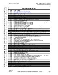
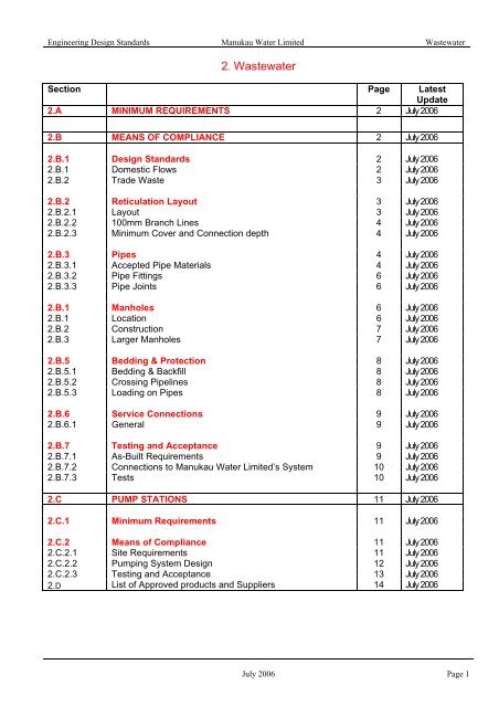
<strong>Engineering</strong> <strong>Design</strong> <strong>Standards</strong> <strong>Manukau</strong> <strong>Water</strong> Limited Wastewater2. WastewaterSection Page LatestUpdate2.A MINIMUM REQUIREMENTS 2 July 20062.B MEANS OF COMPLIANCE 2 July 20062.B.1 <strong>Design</strong> <strong>Standards</strong> 2 July 20062.B.1 Domestic Flows 2 July 20062.B.2 Trade Waste 3 July 20062.B.2 Reticulation Layout 3 July 20062.B.2.1 Layout 3 July 20062.B.2.2 100mm Branch Lines 4 July 20062.B.2.3 Minimum Cover and Connection depth 4 July 20062.B.3 Pipes 4 July 20062.B.3.1 Accepted Pipe Materials 4 July 20062.B.3.2 Pipe Fittings 6 July 20062.B.3.3 Pipe Joints 6 July 20062.B.1 Manholes 6 July 20062.B.1 Location 6 July 20062.B.2 Construction 7 July 20062.B.3 Larger Manholes 7 July 20062.B.5 Bedding & Protection 8 July 20062.B.5.1 Bedding & Backfill 8 July 20062.B.5.2 Crossing Pipelines 8 July 20062.B.5.3 Loading on Pipes 8 July 20062.B.6 Service Connections 9 July 20062.B.6.1 General 9 July 20062.B.7 Testing and Acceptance 9 July 20062.B.7.1 As-Built Requirements 9 July 20062.B.7.2 Connections to <strong>Manukau</strong> <strong>Water</strong> Limited’s System 10 July 20062.B.7.3 Tests 10 July 20062.C PUMP STATIONS 11 July 20062.C.1 Minimum Requirements 11 July 20062.C.2 Means of Compliance 11 July 20062.C.2.1 Site Requirements 11 July 20062.C.2.2 Pumping System <strong>Design</strong> 12 July 20062.C.2.3 Testing and Acceptance 13 July 20062.D List of Approved products and Suppliers 14 July 2006July 2006 Page 1
<strong>Engineering</strong> <strong>Design</strong> <strong>Standards</strong> <strong>Manukau</strong> <strong>Water</strong> Limited Wastewater2.A2.A.12.A.22.A.32.A.42.A.52.A.62.B2.B.1B1.12.B.1.12.B.1.22.B.22.B.2.1MINIMUM REQUIREMENTSThe wastewater system shall be capable of serving the entire natural upstreamcatchment for land uses likely to prevail during the economic life of the system.Where required by reason of sound engineering design practice, the system shall bedesigned and built to include pumped flow to and from adjacent areas. The designperiod shall not be less than 50 years.Unless otherwise approved, all subdivisions shall be designed and constructed witha piped wastewater gravity system that will provide an adequate connection, no lessthan 100mm diameter, to each intended building site, residential or commercial unit,tenancy or allotment and provide a suitable outlet to an approved means ofwastewater disposal.Developments that occur in areas within the Metropolitan Urban Limits withoutadjoining water and wastewater services may be required to contribute to the costsof making those services available to the property in addition to the network GrowthCharge.Isolated small subdivisions in rural areas outside the Auckland Metropolitan Limitsmay be adequately serviced by individual on-site ground disposal systems, inaccordance with the ARC Technical Publication No. 58 and require DischargePermits where necessary. Developments that occur in rural areas outside the MULwill be required to pay a rural NGC. This will be calculated on a case by case basisdepending on the nature of services provided by <strong>Manukau</strong> <strong>Water</strong> Limited.Where the proposed development cannot be adequately serviced by a gravitysystem a public wastewater pump station, in accordance with section C, will beconsidered provided it is located and designed to service the entire area of landbeyond reach of the gravity system.The wastewater system shall be designed to prevent direct stormwater entry into thereticulation system and pump stations.MEANS OF COMPLIANCEDESIGN STANDARDSDomestic FlowsThe wastewater system shall be designed to cater for a peak domestic flowwithout surcharge of 5 times the average dry weather flow of 230litres/person/day for the anticipated population density over the 50-yeardesign life of the system. The system shall generally not be sized for less than0.60 l/s per hectare. Specific design for development in pump stationcatchments shall be required.The design flow shall be based on a “Colebrook - White” pipe roughness coefficientks=1.50 mm and velocity greater than 0.75 m/s. Terminating lines shall have aminimum grade of 1% for 150mm diameter lines and 1.67% for 100mm diameterlines. All lines shall be assumed to flow a minimum of half full.Trade WasteThe specific provision for trade waste disposal within industrial and commercialdevelopments need not be addressed at the subdivisional stage. Any subsequenttrade waste application for a specific site or industry will be subject to approval byUpdated July 2006 Page 2
<strong>Engineering</strong> <strong>Design</strong> <strong>Standards</strong> <strong>Manukau</strong> <strong>Water</strong> Limited Wastewaterapplication to <strong>Water</strong>care Services Ltd.2.B.22.B.2.12.B.2.1.12.B.2.1.22.B.2.1.32.B.2.1.4RETICULATION LAYOUTLayoutThe wastewater reticulation system shall generally consist of pipelines with aminimum internal diameter of 150mm laid to a true grade and line between accessmanholes located at each change of direction, grade and pipe size. The spacebetween manholes shall not exceed 90m. Refer to drawing DS-4 for a typical layout.Wastewater lines of 150mm diameter or greater shall join the main line at a manholejunction.In subdivisions with lot areas less than 600m 2 , the public wastewater system shall belocated in the road reserve or shared access ways, preferably along the footpath witha point of connection accessible from public open space.In subdivisions with lot areas of 600m 2 or more, wastewater lines may be locatedwithin private properties, subject to approval by <strong>Manukau</strong> <strong>Water</strong> Limited, providedthey are:i) In areas that will not reduce the building area available i.e. within front, side andrear yard areas,ii) Clear of permitted building sites,iii) As far as practicable, on the low side of proposed sites.2.B.2.1.52.B.2.22.B.2.2.12.B.2.2.2Where a private pump station is permitted, the rising main shall be connected to thepublic system through a separate manhole located no less than 1.5m from the publicwastewater drains.100mm Branch linesMulti-units are non-free standing buildings. Multi-level units are buildings withseparate titles on more than one floor.100mm diameter public branch lines may be used in accordance with drawing S4.Such lines shall comply with the following:i) Service a maximum of six units in residential or shopping areas, andii) Have a maximum length of 40m, andiii) Have no other connections along the length of the 100mm branch line.2.B.2.32.B.2.3.12.B.2.3.22.B.2.3.3Minimum Cover and Connection depthThe wastewater system shall be designed with sufficient depth not to interfere withother utilities and any future driveway construction, particularly for lots with potentialbasement development.All wastewater lines shall have a minimum cover from the finished ground level of800mm in private land and 1200mm within the road reserve.The minimum level of the private system overflow shall be 1.2m from the serviceconnection invert. At the time of the subdivision, there should be at least a 1.2m fallfrom the lowest ground level within the building site to the service connection invert.Updated July 2006 Page 3
<strong>Engineering</strong> <strong>Design</strong> <strong>Standards</strong> <strong>Manukau</strong> <strong>Water</strong> Limited Wastewater2.B.32.B.3.12.B.3.1.1PIPESAccepted Pipe MaterialsA wastewater reticulation system constructed of the following pipe materials will beaccepted:i) Solid wall PVC manufactured to AS/NZS 1260:2002 class SN16 for both 100and 150mm nominal diameter pipes with minimum wall thickness of 4.1mm and6.3mm respectively. The pipe shall be coloured grey and marked according toAS/NZS 1260 (showing the manufacturer’s name, nominal size, the letters “PVCDWV SN16 AS/NZS 1260” and date of manufacture),ii) Sandwich wall uPVC <strong>Manukau</strong> <strong>Water</strong> Limited approved and manufactured toAS/NZS 1260:2002 class SN16 for both 100 and 150mm nominal diameterpipes,iii) Vitrified clay to comply with EN295.2.B.3.1.2For specific applications the following materials may also be considered:i) Concrete Lined Spiral Welded Steel manufactured to NZS 4442:1988, with oneof the following external protection systems:(a) High Density Polyethylene Sleeve, ‘Black Jacket’ to comply with AS 1518,(b) ‘Polyken Synergy’ wrapping,(c) ‘Polyken YG111’ wrapping.The pipe shall be internally lined with cement mortar lining in accordance withNZS 4442:1998.For pipes above ground and pipe bridges a zinc metal spray sealed with vinyl orepoxy coating to comply with AS/NZS 2312:2002 must be applied,ii) Ductile Iron, concrete lined, class K9 or PN 35, manufactured to AS 2280:2004The pipe shall be externally painted with a bituminous coating and covered with aloose polythene protective sleeve to comply with AS 3680:1989 and applied inaccordance with AS 3681,iii) MDPE, PE80B or PE80C manufactured to AS/NZS 4130:2003, SDR 17,coloured black,iv) mPVC, to comply with <strong>Manukau</strong> <strong>Water</strong> Limited approval.2.B.3.1.3The use of PVC, mPVC and MDPE pipe will not be permitted in the followingsituations without specific approval.i) Mains with a nominal diameter greater than 150mm,ii) In all non-residential developments,iii) Pipelines exceeding 4m in depth.Updated July 2006 Page 4
<strong>Engineering</strong> <strong>Design</strong> <strong>Standards</strong> <strong>Manukau</strong> <strong>Water</strong> Limited Wastewater2.B.3.1.4Consideration for the installation of wastewater pipes by the use of “trenchlesstechnology” will only be given where open cut is not practical from depth andenvironmental considerations. Limitations may be placed on the material, length,gradient, jointing and grouting depending on the method of installation. Refer to C1C1Under verticals are not permitted on all trenchless installations. The maximumover vertical shall be one half of pipe bore.The following shall also apply:i) A minimum grade of 2 % for directional drilling (pipe thrusting) and maximumlength of 20m,ii) A minimum grade of 1 % for laser guided drilling and maximum length of 50m,iii) A minimum grade of 1 % for micro tunnelling and maximum length of 90m.On short lengths of line, socket pipes as in clause 2.B.3.3.1 may be used providedthe oversize installation hole is appropriately grouted.2.B.3.22.B.3.2.1Pipe FittingsAll fittings and service connections shall be factory fabricated of similar material to theproposed system chosen and comply with the relevant standard or <strong>Manukau</strong> <strong>Water</strong>Limited approvals.2.B.3.2.2Where the reticulation system is of PVC or MDPE the main line invert connector toeach manhole structure is to be of composite PVC or MDPE/Vitrified Clay <strong>Manukau</strong><strong>Water</strong> Limited approved connector. The requirements for drop connectors aredetailed in the appropriate <strong>Manukau</strong> <strong>Water</strong> Limited approved drawings.2.B.3.32.B.3.3.1Pipe JointsAll joints on pipes and fittings shall be factory made flexible type complying with thefollowing specification:i) PVC - Spigot and Socket Rubber Ring Joints to AS/NZS 1260:2002. SolventCement Joints to AS/NZS 1260:2002 may be used on trenchless installationsprovided the manufacturer’s guidelines are adhered to, including the requiredperiod to set.ii) Vitrified Clay – Spigot and socket rubber ring joints to EN295,iii) Ductile Iron - AS/NZS 2280:2004,iv) Concrete Lined Spiral Welded Steel – Factory build flange joints, Butt-weldedwith welding band or welded socket and spigot joints. The welded joints shall beprotected with ‘Polyken Synergy’ or ‘Polyken YG111’ wrapping,v) MDPE - Any jointing method is to be detailed upon application,vi) mPVC - Spigot and socket rubber ring joints to PINZ14-1:1997.Updated July 2006 Page 5
<strong>Engineering</strong> <strong>Design</strong> <strong>Standards</strong> <strong>Manukau</strong> <strong>Water</strong> Limited Wastewater2.B.42.B.4.12.B.4.1.12.B.4.1.2MANHOLESLocationManholes shall be located at a maximum spacing of 90m and at the end of allterminal lines greater than 40m in length.150mm branch lines may be terminated with either a blank cap adjoining theterminating ‘London Junction’ or a level invert connector in accordance with clause2.B.6.7, provided the branch lines are:i) Less than 40m long,ii) A maximum of four service connections,iii) Located within a grassed front or side yard area clear of driveways and otherservices.2.B.4.1.32.B.4.22.B.4.2.12.B.4.2.22.B.4.2.32.B.4.2.42.B.4.2.52.B.4.2.6Wherever possible, manholes shall be located clear of overland flow paths.ConstructionManholes shall be of 1050 mm diameter precast concrete with factory fitted bases asdetailed on drawing DS2. Shallow manholes of 675mm as detailed on drawing S3may be installed to a maximum depth of 1200mm at the end of 100mm and 150mmdiameter lines.Outlet pipes from manholes shall have a soffitt level, lower than that of the lowestincoming lines, of 20mm plus 5mm per 10 degrees of angle change between the twolines. For trunk wastewater lines with high flows the grade across the invert of amanhole shall not be less than the general grade of the wastewater line.All manholes shall use <strong>Manukau</strong> <strong>Water</strong> Limited approved manhole covers andframes. Heavy-duty manhole lids are required for use on all roads.All manholes with a depth exceeding 1.2m shall be provided with <strong>Manukau</strong> <strong>Water</strong>Limited approved manhole steps. In non residential areas and other highly corrosiveenvironments, only stainless steel manhole steps shall be used.Each line connecting to a manhole structure shall have an approved flexible jointwithin 600mm of the manhole wall. For PVC pipes, the approved manhole connectorserves as a flexible joint.All incoming wastewater lines shall connect at a minimum angle of 90˚ from themanhole outlet and have a discharge point located along the middle axis of themanhole in accordance with figure below2.B.4.2.7A maximum of 3 invert or 2 internal drop connections (in addition to the through line)shall be allowed into a standard 1050mm diameter manhole. A 675mm diameterconcrete shallow manhole shall have a maximum of 3 invert connections.Updated July 2006 Page 6
<strong>Engineering</strong> <strong>Design</strong> <strong>Standards</strong> <strong>Manukau</strong> <strong>Water</strong> Limited Wastewater2.B.4.32.B.4.3.12.B.4.3.2Larger ManholesThe manhole diameter shall be increased to compensate for the reduced accessspace where more than two internal drop connections or more than three invertconnections (in addition to the through line) are to be installed. Specific design will berequired in sizing such manholes.The manhole diameter shall be increased to 1200mm for all manholes greater than4.5 meters deep.2.B.52.B.5.12.B.5.1.12.B.5.1.22.B.5.1.32.B.5.1.4BEDDING AND PROTECTIONBedding and BackfillAll wastewater lines shall be thoroughly bedded, haunched and backfilled inaccordance with drawing DS7 for PVC,MDPE and mPVC pipelines and drawing S8for Vitrified Clay, Ductile Iron and Concrete Lined Steel pipelines. Backfilling shall becarried out as soon as possible after pipe laying has been completed.Where pipes may be subject to special loadings such as traffic, tree roots orbuildings, special bedding and protection may be required.For wastewater lines laid at grades steeper than 10% (including service connections)the bedding and surround material shall be of a low-grade (5MPa) scoria concrete.For lines exceeding a grade of 20% anchor blocks shall be located at pipe joints, notexceeding 6m spacing as shown on drawing DS-09.Where unstable material is encountered in the bottom of the trench prior to pipelaying the material shall be undercut either until suitable material is reached or untilthe Engineer considers a suitable foundation can be achieved.The trench shall then be backfilled to bedding level with approved hard fill materialplaced in 250mm layers and properly compacted.2.B.5.1.52.B.5.22.B.5.2.12.B.5.32.B.5.3.1Backfilling of the trenches shall be undertaken in such a way to ensure all settlementhas occurred during the phases of sub divisional earthworks, prior to buildingconstruction. Where over width or extra deep trenching is used, the extent andnature of the backfill should be identified on as built fill plans to signify theappropriate use of that area for house construction with respect to foundation andsettlement conditions.Crossing pipelinesThe minimum clearance between any two crossing pipelines should be 300mm.Loading on PipesAll wastewater lines shall be designed and constructed to withstand all the likelyloads they will be subject to during the life of the system. The load carrying capacityin relation to their installation conditions shall be calculated in accordance withAS/NZS 3725:1989 “Loads on buried concrete pipes” and AS/NZS 2566:1998 “Buriedflexible pipelines” where appropriate.Updated July 2006 Page 7
<strong>Engineering</strong> <strong>Design</strong> <strong>Standards</strong> <strong>Manukau</strong> <strong>Water</strong> Limited Wastewater2.B.62.B.6.12.B.6.1.12.B.6.1.22.B.6.1.32.B.6.1.42.B.6.1.52.B.6.1.62.B.6.72.B.72.B.7.12.B.7.1.12.B.7.1.22.B.7.1.3SERVICE CONNECTIONSGeneralTo provide a service connection to each building a 100mm diameter line shall beextended in accordance with drawing S1 from the public wastewater system toterminate a minimum of 1.0m within each site, whether created by cross lease, unittitle or subdivision. Service connections into a concrete manhole shall comply withdrawing DS4.All service connections, from the main wastewater line to the site boundary orconcrete shallow manhole, shall form part of the public system.Service connections shall be laid true to line and grade at right angles to the mainline, and may be connected by a <strong>Manukau</strong> <strong>Water</strong> Limited approved London Junction.Where manholes are conveniently located, service connections shall be directed tothe manholes.The maximum length of all service connections not connected to the manhole shallbe 6.0m from the main line to the site boundary.Service connections shall not be permitted to connect directly to a main line that isdeeper than 4 metres. Connections for the lots to be served shall be provided from anew shallower branch line laid from a manhole on the deep main.In the case of “fee simple” subdivisions where potential exists for further cross leasedevelopment, additional connections may be deferred when the likely siting ofdwellings cannot be readily determined. In these cases, the need for possibleadditional servicing will be identified on the LIR.Where substantial improvements can be made to the drainage alignment by thedeletion of the London Junction at terminal ends of lines, a level invert connector canbe authorised for use in lieu of a London Junction.WASTEWATER AS-BUILT REQUIREMENTSThe as-built plan is to be submitted by the sub-dividers representative to the<strong>Manukau</strong> <strong>Water</strong> Limited field officer at the final testing. They shall submit 5 x A3 sizedcopies to a scale that is clear to read and not less than 1:1000 and shall containthe following information:The Title Plan boundaries and Lot numbers,All existing and new sanitary sewer lines. All new lines to be coloured “Red”,All services shall be labelled with:A/. Flow directionB/. Pipe nominal internal diameter in mm (NB/. PE pipes to show OD)C/. Pipe material e.g. PVC, DI, CLS etcD/. Distance of house connection from centre of downstream manhole, andE/. Depth of each Manhole to 0.1m. Each manhole should be identified as existing ornew e.g. EXMH1 and the nominal diameter should be shown for all sizes other thanthe standard 1050mm size,Updated July 2006 Page 8
<strong>Engineering</strong> <strong>Design</strong> <strong>Standards</strong> <strong>Manukau</strong> <strong>Water</strong> Limited Wastewater2.B.7.1.42.B.7.1.52.B.7.1.62.B.7.1.72.B.7.1.8Relevant surface structures,Final contour plan is only required where changes to the design ground leveloccurred that affect servicing and require further restrictions. Show “Proposed FloorLevel” restriction on Lots that have less than 1.1m from Ground Level (lowest contour)Wastewater Invert level,Schedule of all centre line coordinates of Manholes and terminal points of branch lines(which are greater than 5m long). Schedule of coordinates to 0.1metres in terms ofNZDG2000,Schedule of Manhole Lid levels, Invert levels in and Invert levels out in terms ofLINZ datum and to 0.01m accuracy.Certification of “As-builts” to be by a Chartered Professional Engineer or NZISRegistered Surveyor. This is to be recorded on the as-built to confirm accuracy withinnormal acceptable engineering and surveying tolerances. Council will accept as-builtpreparation by a person holding a NZ Certificate in <strong>Engineering</strong> and/or Surveyingprovided the person is working under the direction of a Chartered ProfessionalEngineer or NZIS Registered Surveyor. For “minor works” in developments asset out in “Appendix 4”, Council will accept as-builts from Registered Drainlayers andPlumbers.2.B.7.22.B.7.2.12.B.7.32.B.7.3.12.B.7.3.22.B.7.3.32.B.7.3.42.B.7.3.5Connections to <strong>Manukau</strong> <strong>Water</strong> Limited’s SystemConnections to public system may only be made under permit by approved licensedcontractors (ALC’s).TestsAll new work shall be inspected and tested before being allowed to be connected tothe existing public wastewater system.All testing including the supply of necessary testing apparatus shall be at theexpense of the developer. The developer must arrange for testing by suitablecontractor(s) in the presence of representative(s) of <strong>Manukau</strong> <strong>Water</strong> Limited.All wastewater lines shall be air-tested according to the ARC <strong>Water</strong>care Servicesrequirements as shown on C3.Upon a satisfactory passing of the air test, at least one and up to a maximum of 20 %of manholes shall be subjected to a rainfall simulation test.The rainfall simulation test shall be as described on C4. Upon failure, the manholeshall be repaired and re-tested. Testing of manholes beyond the limits specified inclause 2.B.7.2.4 maybe required at the discretion of field officers of <strong>Manukau</strong> <strong>Water</strong>Limited.Updated July 2006 Page 9
<strong>Engineering</strong> <strong>Design</strong> <strong>Standards</strong> <strong>Manukau</strong> <strong>Water</strong> Limited Wastewater2.C.2.3.1WASTEWATER PUMPING STATION AS-BUILT REQUIREMENTSThe as-built plans are to be submitted by the sub-dividers representative to the<strong>Manukau</strong> <strong>Water</strong> Limited field officer at the final testing. They shall submit 5 x A3 sizedcopies of the overall layout of the Pump Station. A schedule of coordinates for all WetWells, Storage Wells, Satellite Manholes, Valve Chambers, and Rising Main InspectionChambers etc shall be supplied as well as lid and invert level details of all incomingwastewater lines and rising mains. These as-builts will be used for plotting on to ourGIS system and are to be certified in accordance with the “Wastewater As-builtRequirements”.In addition to the above, <strong>Manukau</strong> <strong>Water</strong> Limited will require for their records, 3 fullcopies ofthe standard drawings PS-01 to PS13 and/or fully approved construction drawingsincluding emergency storage tank, stamped “As-Builts” and should show any changesmade during construction. These as-builts should detail all aspects of the PumpStation construction and to include Wet Well depths/sizes, Overflow Levels, Pumptypes, Rising Main Long sections, Valve Chamber layout details, Storage tanksize/capacity, Electrical layout etc.2.C.2.3.2Pre-constructionA pre-construction meeting shall be arranged with the <strong>Manukau</strong> <strong>Water</strong> LimitedElectro-Mechanical Engineer. The meeting shall be held on site, where <strong>Manukau</strong><strong>Water</strong> Limited shall provide a checklist to be completed before any construction canstart.2.C.2.3.3Inspection and TestingBefore allowing the pump station to be connected to the public system, <strong>Manukau</strong><strong>Water</strong> Limited shall carry out the following:i) Visual inspections of pump station components,ii) A draw-down test of the pump station, andiii) Pressure test of the rising main in accordance with the <strong>Water</strong> Supplyrequirements.Updated July 2006 Page 12
<strong>Engineering</strong> <strong>Design</strong> <strong>Standards</strong> <strong>Manukau</strong> <strong>Water</strong> Limited WastewaterMW APPROVED PRODUCTS, MANUFACTURERS ANDSUPPLIERS FOR USE IN WASTEWATERAPPLICATIONSDRAWING PRODUCT MANUFACTURER SUPPLIERNUMBERMS-1 uPVC Manhole Invert Connector Solo Plastics; Humes;Mico Wakefield;Hynds Pipe Systems Ltd.;Hygrade Products Ltd.MS-2 uPVC London Junction Solo Plastics; Humes;MS-3 Vitrified Clay Drop Junction Clark Pipes; HumesMS-4 Fabricated PVC Drop Junction Solo Plastics Humes;Iplex Pipelines;MS-5 PVC Access Bend Drop Junction Solo Plastics Humes;Iplex Pipelines;MS-6 PE Manhole Connector Solo Plastics;MS-7 Forms for In-situ Formed Channels NZ Channel Forms;MS-8 Eezi liner PE Manhole Channels Eezi liner Ltd.MS-9 uPVC Sandwich Wall Pipe Keyplas Ltd.;Marley NZ Ltd.MS-10 mPVC Sewer and Stormwater Pipe Iplex PipelinesMSR-1Metal Banded Flexible Couplings-AqualineSynapcoKeramoHygradeMSR-2 150mm Clay to uPVC Coupler Solo PlasticsMSR-3 Patch Liner Repair Drain Shift ServicesUpdated July 2006 Page 13