PEL 6 datasheet - Hydrosphere UK Ltd.
PEL 6 datasheet - Hydrosphere UK Ltd.
PEL 6 datasheet - Hydrosphere UK Ltd.
- No tags were found...

You also want an ePaper? Increase the reach of your titles
YUMPU automatically turns print PDFs into web optimized ePapers that Google loves.
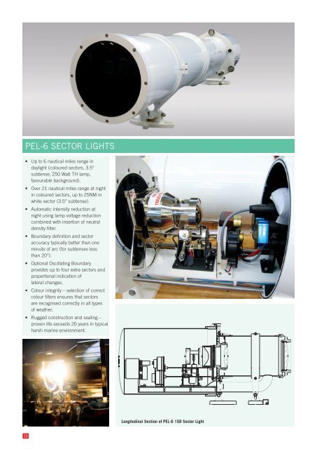
<strong>PEL</strong>-6 SECTOR LIGHTS• Up to 6 nautical miles range indaylight (coloured sectors, 3.5°subtense, 250 Watt TH lamp,favourable background).• Over 21 nautical miles range at nightin coloured sectors, up to 25NM inwhite sector (3.5° subtense).• Automatic intensity reduction atnight using lamp voltage reductioncombined with insertion of neutraldensity filter.• Boundary definition and sectoraccuracy typically better than oneminute of arc (for subtenses lessthan 20°).• Optional Oscillating Boundaryprovides up to four extra sectors andproportional indication oflateral changes.• Colour integrity – selection of correctcolour filters ensures that sectorsare recognised correctly in all typesof weather.• Rugged construction and sealing –proven life exceeds 20 years in typicalharsh marine environment.Longitudinal Section of <strong>PEL</strong>-6 15D Sector Light10
MANUFACTURED BYVEGA INDUSTRIES LTDhttp://www.vega.co.nzSERIAL No: 6-XXX<strong>PEL</strong>-6SECTOREDNAVIGATIONLIGHTSPECIFICATIONSLight SourceLampchangerPower SupplyAnti-Refl ectionCoatingsSector AnglesOscillatingBoundaryNight IntensityReductionM36 250 Watttungsten-halogenlampVega 6-position,VLC-152A(bi-pin mounting)24-28VDC, batteryfl oat (mains or solar)Standard on all<strong>PEL</strong>-6 Sector LightsIndividual sectorscustom-made foreach lightFactory-fi ttedoption for <strong>PEL</strong>-6Sector LightsNight Filter + LampVoltage ReductioncombinedFlash Characters Fixed +255 characters,user-selectableFlasher/Controller CALC-2001computer-assistedlight controllerLamp PowerRegulationConstructionMaterialsExterior fi nishPulse-widthmodulation regulatespower to lampGunmetal, stainlesssteel, copper tubeEpoxy primersurfacer, 2-potpolyurethane glossMeasurement of IntensityWhen checking the intensity of <strong>PEL</strong>Sector Lights the measuring distancemust be suffi cient to ensure that the lightsource behaves as a point source, andthe inverse-square law applies. One wayto check this is to take several readingsat slightly different distances. Whenaccurately done, the source intensity willbe independent of measuring distance.For practical measurements it isacceptable to work close to the limit ofthe photometer’s sensitivity. This couldbe more than 100 metres for some <strong>PEL</strong>-6Sector Lights. Distances less than this willgive false readings on the low side. Analternative method is to use a calibratedzero-range photometric facility, whichsimulates performance of the light atconsiderable distances (in far fi eld).DIMENSIONS<strong>PEL</strong>-6-3.5D483495<strong>PEL</strong>-6-5D483495<strong>PEL</strong>-6-7.5D2551929Left-to-Right Sequence of SectorsSome <strong>PEL</strong> Sector Lights laterally invertthe sector array out in front of the light.The left-to-right sequence of the sectorsas they appear looking into the barrelwill not necessarily be the way theyare projected. Always check sectororientation from a distance.Focus at Infi nity<strong>PEL</strong> Sector Lights are normally focusedat infi nity. This gives sharp sectorboundaries at normal viewing distances.Within the fi rst few hundred metres thesector boundaries will appear blurred.90483 486Clearance to removeRear Can For servicing495495<strong>PEL</strong>-6-15D9751288483 2601100<strong>PEL</strong>-6Mounting Layout189312091398495 714<strong>PEL</strong>-6-10D483 4864807931100218230495144<strong>PEL</strong>-6-20D872Non-Compliant M36 LampsThe original M36 lamp is ideally suitedto the <strong>PEL</strong>-6 Sector Light. Some lampsnow sold as M36 do not comply with theoriginal specifi cation regarding lamp life,fi lament centre height, and pin diametertolerance. These lamps must not beused in <strong>PEL</strong> Lights, as they run at highertemperatures, are prone to explode, andcan crack lenses with excessive heat.For <strong>PEL</strong>-6 lights that are fl ashed, Vegarecommends the use of Bailey M36lamps, which have reinforced fi lamentsupport wires. Other lamps may not givethe rated service life. If in doubt, sourcereplacement lamps from Vega.4535065483 155230240nominalScale 1:2037727527542011
<strong>PEL</strong>-6 Peak Intensities in White, Red and Green Sectors<strong>PEL</strong>-6 Total Subtense Colour 3.5° 5.0° 7.5° 10° 15° 20°M36 Lamp24V 250W THFull IntensityM36 LampNight IntensityReduced to 1%M36 LampNight IntensityReduced to 2%M36 LampNight IntensityReduced to 5%M36 LampNight IntensityReduced to 10%M36 LampNight IntensityReduced to 20%M36 LampNight IntensityReduced to 50%M28 Lamp12V 100W THFull IntensityW 726,532 356,116 158,273 89,199 39,770 22,470R 196,164 96,151 42,733 24,084 10,738 6,067G 174,368 85,468 37,985 21,408 9,545 5,393W 7,265 3,561 1,582 892 398 225R 1,962 962 427 241 107 61G 1,744 855 380 214 95 54W 14,531 7,122 3,164 1,784 795 449R 3,923 1,923 854 482 215 121G 3,487 1,709 759 428 191 108W 36,327 17,806 7,910 4,460 1,989 1,124R 9,808 4,808 2,136 1,204 537 303G 8,718 4,273 1,898 1,070 477 270W 72,653 35,612 15,820 8,920 3,977 2,247R 19,616 9,615 4,271 2,408 1,074 607G 17,437 8,547 3,797 2,141 954 539W 145,306 71,223 31,640 17,840 7,954 4,494R 39,233 19,230 8,542 4,817 2,148 1,213G 34,874 17,094 7,593 4,282 1,909 1,079W 363,266 178,058 79,100 44,600 19,885 11,235R 98,082 48,076 21,357 12,042 5,369 3,033G 87,184 42,734 18,984 10,704 4,772 2,696W 301,674 147,868 65,719 37,038 16,514 9,330R 81,452 39,924 17,744 10,000 4,459 2,519G 72,402 35,488 15,772 8,889 3,963 2,239Vertical Divergence 2.1° 3.0° 3.9° 4.3° 5.0° 5.6°Boundary Resolution
OSCILLATING BOUNDARY AND SECTOR ANGLESOscillating BoundaryDefi nitionOscillating Boundary is a factory-fi ttedoption for any <strong>PEL</strong> Light. It provides upto four additional sectors without anynew colours, and proportional indicationof lateral movement within a sector. TheOscillating Boundary is best appreciatedusing a moving model, as shown on theVega website, www.vega.co.nz.Benefi tThe Oscillating Boundary provides earlywarning of deviation from the centreline, and enables extremely precisenavigation. It is ideal for use by largeships moving in very narrow channels,especially when there is adverse windor tide.Maximum Range RequiredDistance to Control PointLargestVessel atEdge ofChannelSection Through Control PointFl R 3s R Alt R/W W Alt G/W G Fl G 3sFl GGAlt G/ WWAlt R/WRFl RFigure 6Signal FormatIn the oscillating sector the colouroscillates between the colours of thesectors on either side. A completeoscillation occurs every 3 seconds. Theoscillation is seen by an observer withinthe sector as an abrupt changeof colour from red to white (for example),and back to red. The period of time thatone colour is ivisible (relative to the othercolour) is a measure of the closeness ofthe fi xed sector of that colour.The signal is easily and intuitivelygrasped by the mariner. A longer redfl ash and a shorter white fl ash meansthat the mariner is closer to the redsector, and vice versa. Judging theproportion of time in which eachcolour is displayed is quitestraightforward, and the cyclerepeats every three seconds.The Oscillating Boundary signal does notchange when viewed through binoculars.It is a time-based digital signal, ratherthan one based on relative lateraldisplacement.Flash CharacterIt is recommended that a <strong>PEL</strong> Light withOscillating Boundary does not have anyfl ashing character imposed on the lamp,as this combination could be confusing.A character with a longer on-period(for example, 8.0 seconds) could betolerated, followed by a brief off-period.This character would help to confi rm thelight identity to a mariner when holdingposition in the white sector, especially ifthere was signifi cant background lightingat night.Maximum Size of Individual SectorsThere is no restriction on size of fi xedTo calculate sector angles:A1° = atan(W1/C)A2° = atan(W2/C)A° = A 2° - A1°A1°A2°Distance to control point = Csectors. The maximum width of anoscillating sector is limited to 20% of totalsubtense, and all oscillating sectors mustbe the same size.A°By placing the outer fl ashing sectorsoutside the total subtense of the light,they are masked out and not seen. Partialmasking is also possible. See Figure 6.Determining Individual Sector AnglesLargest Vessel at Control PointThe control point is any convenient pointat which the required width of each sectoris established. This could be a restrictedpart of the approach, such as the heads atthe harbour entrance or the entrance to anarrow channel.At the control point consider the largestvessel on the extreme edge of its safemanoeuvring area. Take the centre-lineof the vessel at this point, and set theouter edge of the oscillating sector. Referto example above. When the marinerencounters the fi xed red or green sectors(while standing at the centre of the vessel)he has reached the limit of his safemanoeuvring space.Narrow Centre SectorAt the centre, allow the smallest practicalwhite sector. Half the width of the largestW1distance to centre = W 2centre line of channelFigure 7vessel when at the control point is a usefulstarting value. This format gives a veryearly indication of any deviation from thecentral sector, as the mariner sees a fl ashof red or green depending on whether thevessel has moved left or right.Flashing SectorsWith the Oscillating Boundary systemthere is the option to use part or all ofthe two outside fl ashing sectors.Converting Lateral Distances to AnglesUse the arc-tangent function to convertmeasurements of distance from thecentreline and distance to control pointinto angles in degrees. See Figure 7.Sector Light AlignmentWhen selecting individual sector angles,it is a good idea to place one sector edgeacross a defi ned location, preferably onethat can be reached by land. An observerat this location can easily check thealignment of the entire light from timeto time.Specifying Sector AnglesWhen specifying individual sector angles,always list by colour and size (in degrees),working from left to right as viewed fromthe position of the vessel, looking towardsthe light.13
INSTALLATION GUIDEInstallation of <strong>PEL</strong> Sector LightsLocation of TowerThe tower can be located at anyconvenient place on the extendedcentreline of the required track. Movingthe tower back from the point of closestapproach can help to reduce theunhelpful effect of the beam becomingnarrower and more intense at the pointclosest to the light. Other considerationsare ease of site access for maintenance,security against unauthorised access,availability of existing structure, and levelof background lighting in the viewingdirection (considering day and nightseparately).Height of TowerThe best elevation for the <strong>PEL</strong> Light isat the same height as the bridge of thelargest vessel. This enables the <strong>PEL</strong>Sector Light to be set horizontal. Checkfor adequate vertical divergence. TheSector Light must be visible from all therequired positions. The barrel can beinclined or declined a few degrees ifnecessary. The barrel is exactly parallelto the centreline of the beam.Outside in All WeathersThe <strong>PEL</strong> Light is designed to operateoutside in all climates so no furtherprotection is necessary. If installed insidea lighthouse or other building avoidhaving the beam pass through a glasswindow. This will reduce the intensityof the beam and could reduce theboundary sharpness. Allow the barrelto protrude and seal around it with afl exible membrane.Safe Access for ServicingThe <strong>PEL</strong> Light is best mounted on a stableplate 1000 mm above the fl oor of theservicing platform. The technician needsto check the alignment of each lampwhenever the light is serviced, so safe andcomfortable access is essential. The RearCan needs to be removed to gain access– the <strong>PEL</strong>-3 can hinges down, and the<strong>PEL</strong>-6 can slides back on rails for removal.The front lens of the light must be easilyaccessable for inspection and cleaning, asdirt and grime on this lens will cause thelight output to deteriorate.Design of Mounting Plate<strong>PEL</strong>-3 Lights (except the 3.5D size) havea triangular mounting plate as in photobelow left. The <strong>PEL</strong>-3-3.5D and all <strong>PEL</strong>-6lights have two mounting feet to supportthe weight of the barrel. Refer to the <strong>PEL</strong>-6 dimension drawings for more detail.Unless the holes in the platform can bealigned very accurately they should notbe drilled until the <strong>PEL</strong> Light is positionedand aligned. Some fi ne adjustment(azimuth and elevation) is available in the<strong>PEL</strong> Sector Light mounting.The beam would easily pass over the topof the safety railing.Operating from Commercial PowerWhen an alternating-current (commercialor mains power) source is used, itis strongly recommended that thecommercial power cable is continued rightto the top of the tower. This is better thanterminating at the base of the tower andrunning 12Vdc or 24Vdc cables up thetower, for the following reasons:• no significant voltage drop inthe cables• avoids introducing “inductance”into the low-voltage circuit• reduces susceptibility tolightning damageIn addition, it is strongly recommendedthat a battery is inserted between thepower converter and the <strong>PEL</strong> Sector Lightto provide a measure of autonomy inthe event of a power failure, and furtherinsulate the <strong>PEL</strong> Light from mains voltagespikes. It is well worth making provisionfor lifting batteries up to the platform.Cable lengths between power converter,battery and <strong>PEL</strong> Light should be kept asshort as possible – ideally less than 1m.Vega VPR-39 Power SupplyThis is a weatherproof switch-modepower converter suitable for <strong>PEL</strong> SectorLights operated from commercial power.It accepts 110Vac or 240Vac input, andcan be set to 13.8Vdc or 27.6Vdc output.The VPR-39 can be used to power the<strong>PEL</strong> Light directly or it can be used as acharger when a battery is fi tted.1263Space to slide backand lower Rear Canfor service access<strong>PEL</strong>-3-7DSpace to access frontlens for cleaningSafety Railing1000 mm high209Pedestal for <strong>PEL</strong>-3 Light:1000 mm high withtop plate 300 mm squareScale 1:20300floor of platform775885Servicing platform 1660 mm long for this light14
CALC-2001 & LOGIC INVERTERThe CALC-2001 is a multi-purposemicroprocessor-based controller, and isfi eld programmable. With other plug-indevices it provides all the functionalityrequired by sector lights and otherfl ashed beacons.Lamp switching is via two 40AmpTOP FET’s in parallel. This generousover-rating ensures a low voltage dropand looks after the high inrush current onlamp start up. TOP FET’s provide fastershort-circuit and over-voltage protection.Pulse width modulation is used to controllamp voltage.A Switch Mode Regulator of 1A capacityprovides a constant 12Vdc outputindependent of the input (step up andstep down) for driving the oscillatingboundary, night fi lter, cooling fan, andother devices.User-Selectable Programs are accessedvia four hex switches located under ascrew-in plug. Two hex switches selectany of the 256 available fl ash characters.The third (user) selects the operatingmode (day/night, day only, or night only),and selects sync if required. The fourthswitch is for selecting one of the fi vevoltage reduction steps for night time use,and works for either the 12 or 24V input.Photocell sensitivity is adjusted via twoDIP switches mounted beside the hexswitches. There are four different settingsfor the light level at which switchingoccurs. Photocell hysteresis is fi xed by aresistor.Synchronizing multiple lights is availablewithin one of the user programs. Thesignal is carried by a cable between thelights. The distance between synchronisedlights should not exceed standard RS232parameters. Type 1 sync allows anyor all lights to operate together. Type 2sync requires a return sync pulse froma second light, otherwise the light isdisabled.Logic Inverters control 4-phase steppermotors used to drive oscillating boundaryand night fi lters. They also provide thelogic for night fi lter placement.Lamp Inhibit allows an external signalto switch off the lamp. This is useful forremote control of the lamp to save power.CALC- 2001Temperature Range -40°C to 90°CHousing typeMicroprocessor typeClock speedQuiescent Current (total)Address methodVoltage rangeOutput switching devicesResistive switching loadInput protectionMotor drive outputS.M.R. protectionO-ring SealedMC68HCO5C8Plug in2.4576 MHz65 mAHex Sw x 4 SSpot10 - 28VDC,2 x 40 Amp TOPFET’sSoftstart, CurrentlimitSoftstart, R.P.P &S.S.PRegulator type,S.M.R.3 amp fuse, R.P.P14775S.M.R. load max.1 ampP.W.M. 12V & 24V ±1%Rochfort Instrumentation Made in NZSerial No 3 2 1 SERIESINVERTER LOGIC12VDC1464653.6INVERTER LOGIC12VDCLogic InverterSwitching I.C.Oscillating boundaryIntensity fi lterSAA1027200mA (approx)200mA(intermittent)Serial No 3 2 1 SERIESRochfort Instrumentation Made in NZ<strong>PEL</strong> Fan120mA75 40CALC- 200168.3InverterRange2.5sec - 4.5seccycle15
LAMPCHANGERS FOR <strong>PEL</strong> SECTOR LIGHTSVega High-Wattage Lampchangers• current rating 10.5Amps continuous• lamp power up to 24Vdc, 250W• lamp turret machined from solid brass• excellent heat sinking• high-temperature mica insulation• silver alloy electrical contacts• soft stop to prevent filament damage• reliable and precise indexingmechanism• optional alarm contact on5th/6th position• dual mounting system on all basesVega VLC-150 LampchangerThe VLC-150 lampchanger is standardequipment on <strong>PEL</strong>-3 Sector Lightswhen supplied with pre-focus lamps.It is designed to fi t within the condensersystem of <strong>PEL</strong> Sector Lights, hence thewide gap between turret and escapementmechanism. Other types of lampchangerwould interfere with the mirror.The VLC-150 accepts six marinepre-focus lamps up to 110 Watts(12Vdc, 10.5Amps). Failure of a lampis remotely detected and a 60 degreeturret rotation is actuated by a linearsolenoid and driven by a stainless-steelcoil spring. The Vega soft-stop systemis included. When the last lamp comesinto use, an optional alarm output signalis available.Vega VLC-152AR LampchangerThe VLC-152AR lampchanger isstandard equipment on <strong>PEL</strong>-3 and <strong>PEL</strong>-6Sector Lights when supplied with bi-pintungsten halogen lamps. It is designedto fi t within the condenser system of<strong>PEL</strong> Sector Lights, as the VLC-150 above.The VLC-152AR accepts six lamps up to250 Watts (24Vdc, 10.5 Amps). Failureof a lamp is remotely detected and a 60degree turret rotation is actuated by alinear solenoid and driven by a stainlesssteel coil spring. The Vega soft-stopsystem is included.The VLC-152AR is fi tted with springloadedcollets which ensure the lamp pinsare gripped tightly and with minimumresistance. It is recommended that lamppins are cleaned with very fi ne sandpaperbefore insertion. A special hand tool foropening the collets is stowed on the sideof the lampchanger, and is unscrewed foruse during relamping. A cylindrical “sightgauge” is stowed in the same place,and is slipped over each lamp afterinsertion to check for correct positioning ofthe fi lament.The silver plating on the collets has beenreplaced with a rhodium-plated surfaceto prevent “welding” of the tungsten lamppins into the collets when the lampswere fl ashed.VLC-152BR lampchangerThe optional VLC-152 BR lampchanger,available to special order, can includeisolated monitoring contacts on anextended shaft. These lamp monitoringcontacts can be fi tted to turret positions5 and 6 to give a closed contact indicationfor a remote monitoring system.16
SINGLE <strong>PEL</strong> SECTOR LIGHT APPLICATIONSMark a Leading LineThis is the most common application for a sector light. Thelight can be mounted at any elevation on the desired track,preferably above street-level background lighting, and ina secure location. There is complete fl exibility regardingindividual sectors, and sectors need not be symmetrical. Forextra intensity use two lights mounted one above the other.For very long and narrow channels refer to Parallel Channelexample, as two lights arranged in this way may be requiredto give adequate sensitivity at full range.Supplement a Flashing Beacon (Wellington, NZ)A small fl ashing beacon (with shadow-type fi lters) projectslight through a large angle, and a <strong>PEL</strong> Light supplements thebeacon in the direction of interest, by increasing intensityand sharpening the sector boundaries to defi ne the safepassage. The harbour entrance has many rocky shoals, andaccurate directional guidance is necessary. In the sector inwhich it is visible, the <strong>PEL</strong> light overpowers the signal fromthe fl ashing beacon. Both lights have CALC-2000 controllersand fl ash in sync.Flinders IslandSomesIslandWellington HarbourGreat DogFranklin SoundTwo <strong>PEL</strong>-6-5D SectorLightsOne <strong>PEL</strong>-3-10D Sector LightOne Flashing BeaconOne <strong>PEL</strong>-3-10D Sector LightMark a Fishing Zone or Marine ReserveIn this example a single line is drawn out perpendicular to thecoast, with a different colour each side of the line. A narrowsubtense produces greater intensity, but viewing angle isreduced. A <strong>PEL</strong>-6 light is used, so the signal can be readboth day and night. The light is fl ashed to conserve energy,as the installation is on a remote piece of coast, and must besolar powered. The on-period of 2 seconds is the minimumthat can be used with the 250 Watt lamp to allow time for thelamp to achieve full brilliance.Mark a River Crossing (USA)Vessels cross from one side to the other as deep waterfollows the outside of bends. Crossings move duringfl oods, and aids often need to be realigned. Rear towersfor transit lights are expensive, especially if they need to bemoved from time to time. A <strong>PEL</strong> light can be located on theriverbank, and rotated or repositioned with relative ease. A<strong>PEL</strong>-3-3.5D light with automatic night dimming (and coatedoptics to extract maximum energy) provides day+night useover 1-2NM in several solar-powered installations.Marine ReserveCrossingNon Reserve AreaOne <strong>PEL</strong>-6-20D Sector LightOne <strong>PEL</strong>-3-3.5D Sector Light(with coated optics)17
MULTIPLE <strong>PEL</strong> SECTOR LIGHT APPLICATIONSProvide Extra Subtense (Red Sea)One <strong>PEL</strong>-6-20D light and two <strong>PEL</strong>-6 lights with 10.75° subtenseare mounted on a single station and project a total subtenseof 41°. An overlap of 0.25° between lights ensures the fullsector is covered. A wider coverage is achieved than couldbe provided with a single light, and vertical divergence is less.The relationship between subtense, intensity and colour fi ltertransmission is used to good effect – the intensity from the10.75° lights (in coloured sectors) is about the same as the20° light (in white sector).Mark a Restricted AreaTwo or more lights can be used to provide a fi x over arestricted area. The lights are read as a pair (or group), andmay also be fl ashed in sync to aid identifi cation. The areadefi ned by the lights may be quite irregular. Sectors canbe any size and in any sequence, limited only by the totalsubtense of the light. Restrictions can be to keep vesselsinside (anchoring area, turning basin) or exclude entry(no-anchoring zone, hidden shoal or other danger area).Floating buoys may not be required.Red SeaShoalProjected Display8˚ 25˚ 8˚One <strong>PEL</strong>-6-20D Sector LightTwo <strong>PEL</strong>-3-10.75D Sector LightsTwo <strong>PEL</strong>-3-15D Sector LightsMark a Parallel ChannelThe channel can also be convergent or divergent, and thesame lights used by a dredge. Each light has two sectors,and the lights are read as a pair, perhaps fl ashing in sync.An oscillating sector on the inside of each boundary is possible.This example is used when the taper shape of a single sectoris too much compromise. The advantage of this method overleading lights is that both sector lights only require the intensityof a front lead, and that even at great viewing distances thesensitivity is not reduced.Mark an Undersea Pipeline (Taranaki, NZ)Two wide-angle anamorphic <strong>PEL</strong> Sector Lights are usedto defi ne a no-trawling corridor between an offshore oilproduction platform and the shore station. This is to protectthe underwater pipeline connecting the two. The restrictedarea is defi ned when both lights are red. In this case thelights are not synchronised, but have different characters,and because the background is unlit farmland, relatively lowintensities are adequate. Marker boards are used to defi nethe corridor during the day.PositionABCSignalProduction StationABCPipelineConverging BeamTwo <strong>PEL</strong>-6-5D Sector LightsPositionABCA B CSignalPlatform 22.54NMTwo 150 Anamorphic<strong>PEL</strong> Sector Lights18
OSCILLATING BOUNDARY APPLICATIONSMark a A Turning Track (Tory Channel, NZ)Cook Strait, between the two islands of New Zealand, isa very rough stretch of water with strong tidal rips, and isexposed to strong winds. A regular inter-island rail ferry mustinitiate a turn from inside the sound to exit through an unlitnarrow passage, while remaining clear of rocks on each sideof the channel. The <strong>PEL</strong> Sector Light fi tted with oscillatingboundary provides the pilot of the relatively cumbersomeferry with a progression of distinct sectors to turn through ashe emerges into the strait.Multi-Leg Entrance into a Harbour (Lyttleton, NZ)A 10° <strong>PEL</strong> Sector Light with oscillating boundary provides themain lead into this harbour. The oscillating boundary systemmakes it easier to maintain the correct track, by giving earlywarning of lateral deviation. Once within the inner harbour,a second <strong>PEL</strong> Light (of 5 degrees total subtense for greaterintensity) is used to mark a narrow dredged channel. Thissimple system of two <strong>PEL</strong> Sector Lights replaced a morecomplicated and costly arrangement of shore-based lightsand fl oating buoys.Marlborough SoundsLyttleton HarbourCook StraitOne <strong>PEL</strong>-3-5D Sector LightOne <strong>PEL</strong>-3-5D Sector LightOne <strong>PEL</strong>-3-10D Sector LightDiffi cult Turn Onto Narrow Track (all 7 sectors used)Adverse wind and current makes turning large vesselsdiffi cult. Speed is required to maintain steerage, and extrainformation is needed to execute the turn safely. The use of allseven possible sectors in a <strong>PEL</strong> Sector Light gives the marinerthe best information. Flashing red on fi rst encounter initiatesthe start of the turn. The transition to steady red occurs halfwaythrough the turn, the alternating red/white sector is nexttraversed, and fi nal alignment is gradually achieved within thenarrow white sector.Turning Circle (Mermaid Sound)Two <strong>PEL</strong> Sector Lights are located at a petroleum terminal,and the lights are enclosed in fl ameproof enclosures. Therestricted area of the turning basin is defi ned by these sectorlights. Each white and alternating sector is 100 metres wideat the centre of the basin. The oscillating boundary gives aclear indication of progress around the turning track in eitherdirection, assisting the tanker to arrive at the jetty in thecorrect position. This system is simpler, more reliable and lesscostly to maintain than a buoyage system.Fl GGShip's SignalPosition DisplayedABCDEJettyStar RockTurning BasinCEDBAAlt G/ WWAlt R/WRFl RCooling WaterIntakeOne <strong>PEL</strong>-6-20 Sector LightTwo <strong>PEL</strong> Lights withOscillating Boundary19
Enfi lacion de Bayona (42°7’N, 8°51’W) – Bayona, Galicia, Spain, Autoridad Portuaria de Vigo, built 2007, <strong>PEL</strong>-3 5°. Purpose built lighthouse especially for the Vega<strong>PEL</strong> light. Marks the entrance into Bayona a very pretty town with fantastic natural conditions for leisure boating and fishermen.Head OfficeUnits C&D, West End CentreColthouse Lane, Upper FroyleHampshire, GU34 4JRTel: 01420 520374Fax: 01420 520373sales@hydrosphere.co.ukwww.hydrosphere.co.ukScottish OfficeFife Renewables Innovation CentreAjax Way, MethilFife, KY8 3RSTel: 01333 422000sales@hydrosphere.co.uk<strong>PEL</strong>_Sec_V.2.01_June_13