Instruction manual capaNCDT 6200 (PDF, 1.22 MB) - Micro-Epsilon
Instruction manual capaNCDT 6200 (PDF, 1.22 MB) - Micro-Epsilon
Instruction manual capaNCDT 6200 (PDF, 1.22 MB) - Micro-Epsilon

You also want an ePaper? Increase the reach of your titles
YUMPU automatically turns print PDFs into web optimized ePapers that Google loves.
<strong>Instruction</strong> Manual<strong>capaNCDT</strong> <strong>6200</strong>CS005CS02CSH02CSH02FLCS05CSE05CSH05CSH05FLCS08CS1CSE1CSH1CSH1FLCS1HPCSH1.2CSH1.2FLCSH2FLCS2CSH2CSE2CS3CS5CS10CSG0.50CSG1.00
Non-contact Capacitive Displacement MeasuringMICRO-EPSILONMESSTECHNIKGmbH & Co. KGKönigbacher Strasse 1594496 Ortenburg / GermanyTel. +49 (0) 8542 / 168-0Fax +49 (0) 8542 / 168-90e-mail info@micro-epsilon.dewww.micro-epsilon.comCertified acc. to DIN EN ISO 9001: 2008
Contents1. Safety......................................................................................................................................... 71.1 Symbols Used.................................................................................................................................................. 71.2 Warnings........................................................................................................................................................... 71.3 Notes on CE Identification................................................................................................................................ 81.4 Proper Use........................................................................................................................................................ 91.5 Proper Environment.......................................................................................................................................... 92. Functional Principle, Technical Data ..................................................................................... 102.1 Measuring Principle........................................................................................................................................ 102.2 Structure......................................................................................................................................................... 112.2.1 Sensors.......................................................................................................................................... 122.2.2 Sensor Cable................................................................................................................................. 142.2.3 Controller....................................................................................................................................... 152.3 Technical Data................................................................................................................................................ 172.4 Options........................................................................................................................................................... 183. Delivery ................................................................................................................................... 203.1 Unpacking....................................................................................................................................................... 203.2 Storage........................................................................................................................................................... 204. Installation and Assembly....................................................................................................... 214.1 Precautionary Measures................................................................................................................................. 214.2 Sensor............................................................................................................................................................. 214.2.1 Radial Point Clamping with Grub Screw, Cylindric Sensors........................................................ 214.2.2 Circumferential Clamping, Cylindric Sensors............................................................................... 224.2.3 Flat Sensors................................................................................................................................... 224.2.4 Dimensional Drawings Sensors.................................................................................................... 234.3 Sensor Cable.................................................................................................................................................. 304.4 Controller........................................................................................................................................................ 324.4.1 Basic Unit, Demodulator Module.................................................................................................. 324.4.2 Housing Cover............................................................................................................................... 334.5 Insert Demodulator Module............................................................................................................................ 344.6 Ground Connection, Earthing........................................................................................................................ 37<strong>capaNCDT</strong> <strong>6200</strong>
<strong>capaNCDT</strong> <strong>6200</strong>4.7 Electrical Connections.................................................................................................................................... 384.7.1 Connectivity Options .................................................................................................................... 384.7.2 Pin Assignment Supply, Trigger.................................................................................................... 394.7.3 Pin Assignment Analog Output..................................................................................................... 394.7.4 Pin Assignment Synchronization.................................................................................................. 405. Operation................................................................................................................................. 425.1 Starting Up...................................................................................................................................................... 425.2 Operating or Display Elements...................................................................................................................... 425.2.1 LED‘s............................................................................................................................................. 425.2.2 Poti................................................................................................................................................. 435.2.3 Change Ethernet / EtherCAT......................................................................................................... 445.3 Changing Limit Frequency............................................................................................................................. 445.4 Triggering........................................................................................................................................................ 455.5 Measurement Averaging................................................................................................................................ 475.5.1 Introduction................................................................................................................................... 475.5.2 Moving Average............................................................................................................................. 475.5.3 Arithmetic Average Value.............................................................................................................. 485.5.4 Median........................................................................................................................................... 485.5.5 Dynamic Noise Rejection.............................................................................................................. 486. Ethernet Interface.................................................................................................................... 496.1 Hardware, Interface........................................................................................................................................ 496.2 Data Format of Measuring Values.................................................................................................................. 536.3 Settings........................................................................................................................................................... 546.4 Commands..................................................................................................................................................... 576.4.1 Data Rate (STI).............................................................................................................................. 576.4.2 Trigger Mode (TRG)....................................................................................................................... 596.4.3 Get Measured Data (GMD)........................................................................................................... 596.4.4 Filter, Averaging Type (AVT).......................................................................................................... 606.4.5 Filter, Averaging Number (AVN).................................................................................................... 606.4.6 Channel Status (CHS)................................................................................................................... 616.4.7 Mode of Linearization (LIN)........................................................................................................... 616.4.8 Set Linearization Point (SLP)......................................................................................................... 626.4.9 Get Linearization Point (GLP)........................................................................................................ 636.4.10 Status (STS).................................................................................................................................. 636.4.11 Version (VER)................................................................................................................................ 646.4.12 Set Mathematic Function (SMF).................................................................................................... 646.4.13 Get Mathematic Function (GMF)................................................................................................... 66
Appendix................................................................................................................................................. 85A 1 Accessories, Service............................................................................................................... 85A 1.1 Conversion Kit................................................................................................................................................. 85A 1.3 PC<strong>6200</strong>-3/4..................................................................................................................................................... 87A 1.4 Optional Accessories...................................................................................................................................... 87A 1.5 Service............................................................................................................................................................ 90A 2 Factory Setting........................................................................................................................ 91A 3 Tilt Angle Influence on the Capacitive Sensor...................................................................... 92A 4 Measurement on Narrow Targets........................................................................................... 93A 5 Measurements on Balls and Shafts....................................................................................... 94A 6 EtherCAT Documentation....................................................................................................... 95A 6.1 Preamble......................................................................................................................................................... 95A 6.2 CoE – Object Directory................................................................................................................................. 100A 6.3 Measurement Data Format........................................................................................................................... 106A 6.4 EtherCAT Configuration with the Beckhoff TwinCAT©-Manager................................................................. 107<strong>capaNCDT</strong> <strong>6200</strong>
Safety1. SafetyKnowledge of the operating instructions is a prerequisite for equipment operation.1.1 Symbols UsedThe following symbols are used in this instruction <strong>manual</strong>:i1.2 WarningsIndicates a hazardous situation which, if not avoided, may result in minor or moderateinjury.Indicates a situation which, if not avoided, may lead to property damage.Indicates a user action.Indicates a user tip.Disconnect the power supply before touching the sensor surface.> > Danger of injury> > Static dischargeConnect the power supply and the display/output device in accordance with the safety regulations for electricalequipment.> > Danger of injury> > Damage to or destruction of the sensor and/or controllerAvoid shock and vibration to the sensor and controller.> > Damage to or destruction of the sensor and/or controllerThe power supply may not exceed the specified limits.> > Damage to or destruction of the sensor and/or controller<strong>capaNCDT</strong> <strong>6200</strong>Page 7
Functional Principle, Technical Data2. Functional Principle, Technical Data2.1 Measuring PrincipleThe principle of capacitive distance measurement with the <strong>capaNCDT</strong> system is based on the principle of theparallel plate capacitor. For conductive targets, the sensor and the target opposite form the two plate electrodes.If a constant AC current flows through the sensor capacitor, the amplitude of the AC voltage at the sensor isproportional to the distance between the capacitor electrodes. The AC voltage is demodulated, amplified andoutput as an analog signal.The <strong>capaNCDT</strong> system evaluates the reactance X Cof the plate capacitor which changes strictly in proportionto the distance.1X c = ; capacitance C = * *jCr oiareadistanceA small target and bent (uneven) surfaces cause a non-linear characteristic.This theoretical relationship is realized almost ideally inpractice by designing the sensors as guard ring capacitors.The linear characteristic of the measuring signal isachieved for electrically conductive target materials(metals) without any additional electronic linearization.Slight changes in the conductivity or magnetic propertiesdo not affect the sensitivity or linearity.GroundScreening electrodeMeasuring electrodeElectrical conductorFig. 1 Functional principle of the guard ringcapacitor<strong>capaNCDT</strong> <strong>6200</strong>Page 10
Functional Principle, Technical Data2.2 StructureThe non-contact, multi-channel measuring system, installed in an aluminum housing, consists of:--A basic module DT 6220 or DT 6230--A demodulator module DL 6220 or DL 6230, each with integrated preamplifier per sensor--Sensor--Sensor cable--Power supply cable--Ethernet cable--Signal output cableThe modular assembly allows to join up to 4 channels (module system).EthernetEtherCATVoltage0..10 VCurrent4..20mASensorVoltage0..10 VCurrent4..20mASensorTrigger<strong>Micro</strong> controllerOutput circuitAnalog filterdigitalswitchableZero pointadjustablepotiPreamplifierOutput circuitAnalog filterdigitalswitchableZero pointadjustablepotiPreamplifierDemodulatorDemodulatorOscillatorA/DconverterA/DconverterSupply12 ... 36 VVoltageconditioningDT 6220 / 6230 DL 6220 DL 6220Fig. 2 Block diagram <strong>capaNCDT</strong> <strong>6200</strong><strong>capaNCDT</strong> <strong>6200</strong>Page 11
Functional Principle, Technical Data2.2.1 SensorsFor this measurement system, several sensors can be used.In order to obtain accurate measuring results, keep the surface of the sensor clean and free from damage.The capacitive measuring process is area-related. A minimum area (see table) is required depending on thesensor model and measuring range. In the case of insulators the dielectric constant and the target thicknessalso play an important role.Sensors for electrical conducting targets (metals)Sensor model Measuring range Min. target diameterCS005 0.05 mm 3 mmCS02 0.2 mm 5 mmCSH02 0.2 mm 7 mmCSH02FL 0.2 mm 7 mmCS05 0.5 mm 7 mmCSE05 0.5 mm 6 mmCSH05 0.5 mm 7 mmCSH05FL 0.5 mm 7 mmCS08 0.8 mm 9 mmCS1 1 mm 9 mmCSE1 1 mm 8 mmCSH1 1 mm 11 mmCSH1FL 1 mm 11 mmCS1HP 1 mm 9 mmCSH1,2 1.2 mm 11 mmCSH1.FL 1.2 mm 11 mm<strong>capaNCDT</strong> <strong>6200</strong>Page 12
Functional Principle, Technical DataSensor model Measuring range Min. target diameterCSH2FL 2 mm 17 mmCS2 2 mm 17 mmCSH2 2 mm 17 mmCSE2 2 mm 14 mmCS3 3 mm 27 mmCS5 5 mm 37 mmCS10 10 mm 57 mmCSG0.50 0.5 mm approx. 7 x 8 mmCSG1.00 1.00 mm approx. 8 x 9 mm<strong>capaNCDT</strong> <strong>6200</strong>Page 13
Functional Principle, Technical Data2.2.2 Sensor CableSensor and controller are connected by a special, double screened, 1 m (3 ft) long sensor cable.Do not shorten or lengthen these special cables.Usually, a damaged cable can not be repaired.Switch off the device when plugging and removing connectors.Do not crush the sensor cable.Do not modify to the sensor cable.> > Lost of functionalityModel Cable length 2 axial 1x axial For sensors Min. bending radiusconnector + 1x 90 0 once permanentlyCCxC 1/2 or 3 m • 0.05 - 0.8 mmCCxC/90 1/2 or 3 m • 0.05 - 0.8 mm10 mm 38 mmCCxB 1/2 or 3 m • 1 ... 10 mmCCxB/90 1/2 or 3 m • 1 ... 10 mmCCmxC 1.4/2.8 or 4.2 m • 0.05 - 0.8 mmCCmxC/90 1.4/2.8 or 4.2 m • 0.05 - 0.8 mm7 mm 15 mmCCmxB 1.4/2.8 or 4.2 m • 1 ... 10 mmCCmxB/90 1.4/2.8 or 4.2 m • 1 ... 10 mmThe sensors of type CSH have integrated a 1.4 long sensor cable. Cable lengths of 2.8 m are available too ifrequired.Other cable lengths are also available on request.The sensor model CSE1 (measuring range 1 mm) has the connector type C.<strong>capaNCDT</strong> <strong>6200</strong>Page 14
Functional Principle, Technical Data2.2.3 ControllerThe <strong>capaNCDT</strong> <strong>6200</strong> Multi-channel measuring system consists of a basic module DT62xx and one up to fourdemodulator modules DL62xx, according to requirements. The components are stored in aluminum housings.Basic moduleDemodulator module(s)Basic moduleDemodulator module(s)<strong>capaNCDT</strong> <strong>6200</strong>Fig. 3 Front view basic module DT6220 with2 demodulator modules DL6220Basic module DT62xxFig. 4 Front view basic module DT6230 withdemodulator module DL6230 and DL6220The basic module consists of the units voltage conditioning, oscillator and digital unit.The voltage conditioning generates all required internal voltages from the supply voltage, both for the basicmodule as well as the connected demodulator modules. The oscillator supplies the demodulator moduleswith constant frequency and amplitude-stable alternating current. The frequency is 31 kHz. The digital unitcontrols the A/D converter of the demodulator modules and measures the actual measuring values. The measuringvalues can be read out via the Ethernet interface in digital form, see Chap. 6.Page 15
Functional Principle, Technical DataDemodulator module DL62xxThe demodulator module DL62xx consists of an internal preamplifier, demodulator, output stage and A/Dconverter. The internal preamplifier generates the distance dependent measuring signal and amplifies it.Demodulator and output stage convert the measuring signal in a standardized voltage and current signal.The measuring values can be processed digitally with the help of the A/D converter.The trim potentiometer zero allows a special zero adjustment of the analog output signals, see Fig. 3.Output voltage can achieve up to 15 VDC, if the sensor is disconnected respectively exceedance ofmeasuring range.i<strong>capaNCDT</strong> <strong>6200</strong>Page 16
Functional Principle, Technical Data2.3 Technical DataController type DT62x0 with DL6220 DT62x0 with DL6230Resolution static 0.004 % FSO 0.0005 % FSOResolution dynamic 0.02 % FSO (5 kHz) 0.005 % FSO (5 kHz)Bandwidth 5 kHz (-3dB) 5 kHz (-3dB)Bandwidth adjustable to 20 Hz to 20 HzData rate output digital max. 3.906 kSa/s max. 3.906 kSa/sLinearity≤ ±0.2 % FSOOption: ±0.1 % FSO(tuned to one sensor)≤ ±0.2 % FSOOption: ±0.1 % FSO(tuned to one sensor)Max. sensitivity deviation ≤ ±0.1 % FSO ≤ ±0.1 % FSOLong term stability ≤ 0.02 % FSO / month ≤ 0.02 % FSO / monthSynchronous operation supported(multiple control units)nonoIsolator measurement no noTemperature stability 200 ppm 200 ppmTemperature range (operation) +10 … +60 °C (+50 ... +140 °F) +10 … +60 °C (+50 ... +140 °F)Temperature range (storage) -10 … +75 °C (+14 ... +167 °F) -10 … +75 °C (+14 ... +167 °F)SupplyDT6220: 24 VDC (12 … 36 VDC)DT6230: 24 VDC (15 ... 36 V)24 VDC (15 … 36 VDC)DT62203.1 W (typical)Power consumption at24 VDCOutputDT6230per DL6220per DL62303.8 W (typical)1.8 W (typical); 2.0 W (max.)1.9 W (typical); 2.2 W (max.)0 … 10 V (short-circuit proof) 0 … 10 V (short-circuit proof)4 … 20 mA (load max. 500 Ohm) 4 … 20 mA (load max. 500 Ohm)EthernetEthernet<strong>capaNCDT</strong> <strong>6200</strong>Page 17
Functional Principle, Technical DataController type DT62x0 with DL6220 DT62x0 with DL6230Sensors all sensors suitable all sensors suitableSensor cable standard 1 m 1 mSensor cable (matched) ≤ 3 m (with CCxx) ≤ 4.2 m (with CCmxx) ≤ 3 m (with CCxx) ≤ 4.2 m (with CCmxx)Trigger TTL, 5 V TTL, 5 VFSO = Full Scale Output2.4 OptionsArticle number Designation Description Suitable for articles29820442982045LC DL62x0digitalLC DL62x0analog2982046 ECL2 DL62202982047 ECL3 DL62202982048 EMR2 DL62202982049 RMR1/2 DL62202303018DL6220Special calibration of linearity on digitaloutputSpecial calibration on linearity on analogoutputSpecial tuning for longer sensor cables2.0 m (with CCxx);2.8 m (with CCmxx)Special tuning for longer sensor cables3.0 m (with CCxx);4.2 m (with CCmxx)Extended measuring (factor: 2) contains"LC DL62x0 digital" and"LC DL62x0 analog"Reduced measuring range (factor: 1/2)contains "LC DL62x0 digital" and"LC DL62x0 analog"2303022DL6220/ECL22303023DL6220/ECL32303029DL6220/LC○ ○ ○ •○ ○ ○ •- • - •- - • •○ ○ ○ •○ ○ ○ •<strong>capaNCDT</strong> <strong>6200</strong>Page 18
Functional Principle, Technical DataArticle number Designation Description Suitable for articles29820442982045LC DL62x0digitalLC DL62x0analog2982054 ECL2 DL62302982055 ECL3 DL62302982051 EMR2 DL62302982052 EMR3 DL62302982053 RMR1/2 DL6230• Articles already contain the option○ Option available- No option availableSpecial calibration of linearity on digitaloutputSpecial calibration of linearity on analogoutputSpecial tuning for longer sensor cables2.0 m (with CCxx);2.8 m (with CCmxx)Special tuning for longer sensor cables3.0 m (with CCxx);4.2 m (with CCmxx)Extended measuring range (factor: 2)contains “LC DL62x0 digital” and“LC DL62x0 analog”Extended measuring range (factor: 3)contains “LC DL62x0 digital” and“LC DL62x0 analog”Reduced measuring range (factor: 1/2)contains “LC DL62x0 digital” and“LC DL62x0 analog”2303019DL62302303024DL6230/ECL22303025DL6230/ECL32303030DL6230/LC○ ○ ○ •○ ○ ○ •- • - •- - • •○ ○ ○ •○ ○ ○ •○ ○ ○ •<strong>capaNCDT</strong> <strong>6200</strong>Page 19
Delivery3. Delivery3.1 Unpacking1 Basic module DT62x0 with 1 - 4 demodulator modules DL62x01 Power supply and trigger cable PC<strong>6200</strong>-3/4, 3 m long, see Chap. A 1.31 Ethernet cable, 3 m long1 CD (contains instruction <strong>manual</strong> and software)1 Conversion kit (Springs for mounting on DIN-rail, mounting plates for wall fastening, threaded rods in differentlengths), see Chap. A 1.1.Optional accessories:1 Sensor1 Sensor cable with connectorSignal output cable, synchronization cable, see Chap. A 1.4Remove the parts of the system carefully from the packaging and transport them in such a way that theyare not damaged.Check for completeness and shipping damages immediately after unpacking. In case of damage ormissing parts, please contact the manufacturer or supplier.3.2 Storage--Storage temperature:• Sensor: -50 ... +200 °C (-58 to +392 °F) 1• Sensor cable: -50 ... +200 °C (-58 to +392 °F)• Controller:-10 ... +75 °C (+14 to +167 °F)--Humidity: 5 - 95 % RH (non condensing)<strong>capaNCDT</strong> <strong>6200</strong>1) A storage temperature of -50 ... +100 °C (-58 to +212 °F) applies for the sensors CSG0.50-CA andCSG1.00-CA -50Page 20
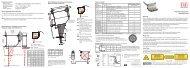
Installation and Assembly4. Installation and Assembly4.1 Precautionary MeasuresNo sharp-edged or heavy objects may get into contact with the sensor cable sheath.Protect the cable against pressure loads in pressurised rooms.iAvoid kinks in any case.Check the connections for tight fit.A damaged cable cannot be repaired.4.2 SensorThe sensors may be mounted free-standing or flush.When assembling, make sure that the polished sensor surface is not scratched.4.2.1 Radial Point Clamping with Grub Screw, Cylindric SensorsThis simple type of fixture is only recommended for a force and vibration-free installation position. The grubscrew must be made of plastic so that it cannot damage or deform the sensor housing.Grub screwFig. 5 Radial point clamping with grub screwDo not use metal grub screws!> > Danger of damaging the sensor<strong>capaNCDT</strong> <strong>6200</strong>Page 21
Installation and Assembly4.2.2 Circumferential Clamping, Cylindric SensorsThis sensor mounting option offers maximum reliability because the sensor is clamped around its cylindricalhousing. It is absolutely necessary in difficult installation environments, for example on machines, productionplants et cetera.Mounting withclamping ringFig. 6 Circumferential clampingiTension at the cable is inadmissible!4.2.3 Flat SensorsFlat sensors are mounted by means of a tap hole for M2 (in case of sensors 0.2 and 0.5 mm) or by a throughhole for M2 screws. The sensors can be bolted on top or below.Screwing from aboveScrewing from bottom<strong>capaNCDT</strong> <strong>6200</strong>Page 22
Installation and Assembly4.2.4 Dimensional Drawings SensorsCylindric sensorsCS005CS02CS05CSE05CS08ø3 (0.118 dia.)11 (.433)12(.472)ø6f7(.236 dia.)12(.472)ø6f7 (.236 dia.)12(.472)ø8f7 (.314 dia.)9 (.35)12 (.47)ø5.7 (.22)ø6f7(.24 dia.)15 (.59)ø10f7(.394 dia.)Connector sideDimensions in mm(inches)Circumferential clampingpossible from 3 mmbehind the front face.Dimensional drawingsof other sensors areavailable on request.CS1HP20 -0.2(.787 -0.008 )ø10f7 (.394 dia.)CS1ø10f7 (.394 dia)-0 008)21 -0.2 (o.83CSE1ø8f7 (0.31 dia.)ø7.7 (0.30 dia.)9 (0.35)12 (0.47)CS2M=1:2ø20h7 (.79 dia.)24 -0.2(.945) -0.008<strong>capaNCDT</strong> <strong>6200</strong>Page 23
Installation and AssemblyConnector sideDimensions in mm(inches)Circumferential clampingpossible from 3 mmbehind the front face.Dimensional drawingsof other sensors areavailable on request.M=1:2CS3ø30h7 (1.18 dia.)16.5 ( .649)24 -0.2(.945) -0.008ø20h7 (.79 dia.)M=1:2CS5ø40h7 (1.58 dia.)16.5 (.649)ø20h7 (.79 dia.)24 -0.2(.945) -0.008M=1:2CS10ø60h7 (2.36 dia.)ø20h7 (.79 dia.)24 -0.2 (0.94 -0.008 )16.5 (0.65)<strong>capaNCDT</strong> <strong>6200</strong>Page 24
Installation and AssemblyCSH02-CAmx,CSH05-CAmxca. 9.4 (.37)CSH1-CAmx,CSH1.2-CAmxca. 9.4 (.37)ø8g6 (.315 dia.)ø12g6 (.473 dia.)10 (.39)14(.39)ø11.5(.45 dia.)33(1.30)14(.39)ø7.5(.30 dia.)ca. 37 (1.46)10 (.39)33(1.30)ca. 37 (1.46)ø2.2 (.09 dia.)ø2.2 (.09 dia.)Dimensions in mm (inches), not to scale<strong>capaNCDT</strong> <strong>6200</strong>Page 25
Installation and Assemblyø20g6 (.79)CSH2-CAmxappr. 9.4 (.37)33 (1.3)10 (.39)14 (.55)ø19.5 (.77)appr. 37 (1.5)ø2.2 (.09)Dimensions in mm (inches), not to scale<strong>capaNCDT</strong> <strong>6200</strong>Page 26
Installation and AssemblyFlat sensorsCSH02FL-CRmx,CSH05FL-CRmx4 (.16)0.1 (.003)3.5(.14)4(.16)ø3(.12 dia.)M2R4 (.16)1.75(.07)5.5(.22)6.5(.25)ca. 9.4 (.37)ca. 37 (1.46)ø4(.16 dia.)4 (.16)0.1(.003)4.5(.18)5(.20)ø2.5(.10)ø3(.12 dia.)CSH1FL-CRmx,CSH1.2FL-CRmxR6(.24)2.25(.09)7.5(.29)11 (.43)ca. 9.4 (.37)ca. 37 (1.46)ø2.2(.09)ø2.2 (.09)Dimensions in mm (inches), not to scale<strong>capaNCDT</strong> <strong>6200</strong>Page 27
Installation and AssemblyCSG0.50-CAm2.0 and CSG1.00-CAm2.020.2 (0.80)Sensor structuresThickness 0.9 -0.05 (0.04 -0.002 ) Sensor structures200 (7.87)216 (8.5)9.9 (0.39)1 (0.04)15(0.59)R24.2 (0.17)2.9(0.11)5.4(0.21)4.5(0.18)CSG0,50-CAm2,04.2 (0.17)6.2 (0.24)4.4(0.17)3.85(0.15)CSG1,00-CAm2,0Dimensions in mm (inches), not to scale<strong>capaNCDT</strong> <strong>6200</strong>Page 29
Installation and Assembly4.3 Sensor CableThe sensor is connected to the controller by the sensor cable. The connection is made by simple plugging.The connector locks automatically. The tight fit can be checked by pulling the connector housing (cablebushing). The lock can be released and the connector can be opened by pulling the knurled housing sleeveof the cable bushing.Ø5.4 (.21)Ø6 (.24)8.6 (.34)13.7 (.54)17.5 (.69)Sensor cable CCxCØ3.2Cable length x27 (1.06)37 (1.46)Ø7 (.28)Ø9.6 (.38)Sensor cable CCxC/9016 (10.08)8 (.31)16.9 (.67)13.1(.52)Ø6 (.24)Ø5.4 (.21)Sensor cable CCxBCable length xØ3.2(.13)Dimensions in mm (inches), not to scale27 (1.06)37 (1.46)Ø7 (.28)Ø9.5 (.37)Sensor cable CCxB/9025 (.98)20.5 (.81)30.5 (1.20)Ø10 (.39)Ø7 (.28)<strong>capaNCDT</strong> <strong>6200</strong>Model Cable length 2 axial connector 1x axial + 1x 90 0 For sensors Min. bending radiusCCxC 1/2 or 3 m • 0.05 - 0.8 mmCCxC/90 1/2 or 3 m • 0.05 - 0.8 mm 10 mm 38 mmCCxB 1/2 or 3 m • 1 ... 10 mm (once) (permanently)CCxB/90 1/2 or 3 m • 1 ... 10 mmPage 30
Installation and AssemblyØ5.4 (.21)Ø6 (.24)8.6 (.34)13.7 (.54)Sensor cable CCmxCØ2.117.5 (.69)Cable length x27 (1.06)37 (1.46)Ø7 (.28)Ø9.6 (.38)Sensor cable CCmxC/9016.9 (.67)8 (.31)13.1(.52)16 (10.08)Ø6 (.24)Ø5.4 (.21)Sensor cable CCmxBCable length xØ2.1(.08)Dimensions in mm (inches), not to scale27 (1.06)37 (1.46)Ø7 (.28)Ø9.5 (.37)Sensor cable CCmxB/9025 (.98)30.5 (1.20)20.5 (.81)Ø10 (.39)Ø7(.28)Model Cable length 2 axial connector 1x axial + 1x 90 0 For sensors Min. bending radiusCCmxC 1.4/2.8 or 4.2 m • 0.05 - 0.8 mmCCmxC/90 1.4/2.8 or 4.2 m • 0.05 - 0.8 mmCCmxB 1.4/2.8 or 4.2 m • 1 ... 10 mmCCmxB/90 1.4/2.8 or 4.2 m • 1 ... 10 mm7 mm(once)15 mm(permanently)<strong>capaNCDT</strong> <strong>6200</strong>Page 31
Installation and Assembly4.4 Controller4.4.1 Basic Unit, Demodulator Module34 (1.34) 25 (.98) 125 (4.92)90 (3.54)DT 6220 DL 6220Fig. 7 Dimensional drawing controllerDimensions in mm (inches), not to scale<strong>capaNCDT</strong> <strong>6200</strong>Page 32
Installation and Assembly4.4.2 Housing Cover4 (0.16)90 (3.54)M48 (.31)Mounting hole M4 forwall fastening respectivelymounting on DIN-rail125 (4.92)5(.20)8(.31)2x M450 (1.97)5(.20)8(.31)Fig. 8 Dimensional drawing housing coverDimensions in mm (inches), not to scaleThe controller is mounted using mounting plates or holding clamps for a mounting on DIN-rail which areincluded with the conversion kit supplied, see Chap. A 1.1.<strong>capaNCDT</strong> <strong>6200</strong>Page 33
Installation and Assembly4.5 Insert Demodulator ModuleiUnscrew the sleeve nuts (4b) on the right side of the controller, remove the right housing cover (3).Remove a sleeve nut (4a) with threaded rod (1).Successively replace the threaded rod (1) by a threaded rod next longer from the supplied conversionkit. Move the new threaded rod with the sleeve nut (4a) through the modules.Exchange the remaining 3 threaded rods in such a way.Touch the demodulator modules only at the housing, not at the electronics. This will prevent electrostaticdischarges on the electronics.Attach the additional demodulator module.4a1 2 3 4bNumber demodulatormodulesLengththreaded rod M41 59 mm2 84 mm3 109 mmETHERNETRangeLP FilterRangeLP FilterZero4 134 mmZeroZeroZeroSENSOR/CPSENSOR/CPPOWER/TRIG.SIGNAL OUTSIGNAL OUTDT6220 DL6220 DL6220Fig. 9 Mechanical components controllerConnect both flat flexible cables (5) of the preceding demodulator module with the new demodulatormodule (6).<strong>capaNCDT</strong> <strong>6200</strong>Page 34
Installation and Assembly55 Wiring preceding demodulatormodule6 Wiring following demodulatormodule65Put on the right housing cover (3).Fig. 10 Wiring demodulator modulesScrew the sleeve nuts (4b) on the threaded rods on the right side of the controller and tighten the sleevenuts.<strong>capaNCDT</strong> <strong>6200</strong>Page 35
Installation and AssemblyThe wiring to the preceding demodulator module (5) can be solved using the supplied plugging off assistanceas follows:1. Press the plugging off assistance with the recess laterally to the connector (5).2. Loosen the connector with a lever movement.3. Loosen the other side of the connector in the same way.2.1.3.Fig. 11 Use of the plugging off assistance for the wiring of the demodulator elements<strong>capaNCDT</strong> <strong>6200</strong>Page 36
Installation and Assembly4.6 Ground Connection, EarthingMake sure you have a sufficient grounding of the measuring object, for example connect it with the sensoror the supply ground.Non-contact target earthingIn several applications, the target earthing is difficult or even impossible.Different to other systems, with <strong>capaNCDT</strong> systems is no target earthing necessaryThe drawing below shows two synchronized <strong>capaNCDT</strong> sensors, measuring against a mill, see Fig. 12. Dueto the unique synchronizing technique of MICRO-EPSILON a special target earthing is not needed in mostcases.SensorSensorControllersync.ControllerGround connectionFig. 12 Position and unbalance measuring with twomeasuring systemsFig. 13 Ground connection on the housing coverNo target grounding required with two synchronized <strong>capaNCDT</strong> sensors.If necessary use the ground connection on the housing cover. The ground connection is included with theconversion kit supplied, see Chap. A 1.1.<strong>capaNCDT</strong> <strong>6200</strong>Page 37
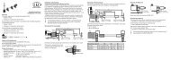
Installation and Assembly4.7 Electrical Connections4.7.1 Connectivity OptionsThe power supply and the signal output are located at the front side of the controller.ControllerLAN cable with RJ-45 connectorsEtherCATCCxxxSPSPC<strong>6200</strong>-3/4PS 2020SCACx/4SensorEthernetPCDDxxFig. 14 Measuring system assembly<strong>capaNCDT</strong> <strong>6200</strong>Page 38
Installation and Assembly4.7.2 Pin Assignment Supply, TriggerPINColorPC<strong>6200</strong>-3/4SignalDescriptionETHERNET1 brown +24VIN +24 VDC Supply2 white Zero VIN GND Supply413 yellow TRI_IN+ Trigger IN+, TTL level4 green TRI_IN- Trigger INshieldPC6000-3/4 is a 3 m (13.12 ft) long, pre-assembled powersupply and trigger cable.4.7.3 Pin Assignment Analog OutputPinColorSCACx/4Signal Description1 brown U-outU OUT,(Load min. 10 kOhm)2 yellow I-outI OUT,(Load max. 500 Ohm)3 grey AGND Analog ground4 white AGND Analog groundshieldAnalog grounds are connected internally. SCACx/4 is a3 m (13.12 ft) long, 4-wire output cable. It is supplied as anoptional accessory.3 2POWER/TRIG.View on solder pin side,4-pole ODU femalecable connectorU AUSI AUSAGNDAGNDView on solder pinside, 4-pole malecable connectorDT62xxPower supply inputon controller, 4-polemale cable connectorRangeLP FilterZeroZeroSENSOR/CPSIGNAL OUTDL62xxSignal output on controller,4-pole male cableconnector<strong>capaNCDT</strong> <strong>6200</strong>Page 39
Installation and Assembly4.7.4 Pin Assignment SynchronizationPIN Assignment Insulation Color1 n.c - -2 Twisted Pair 1 1 white 13 Twisted Pair 1 blue blue4 Twisted Pair 2 2 white 25 Twisted Pair 2 orange orangeSC6000-x is a 0,3 or 1 m long, preassembled synchronizationcable213 45View on solder pinside,5-pin ODU malecable connectorPOWER/TRIG.ETHER AT IN ETHERCAT OUTETHERNETSYNCINOUTSync IN/OUT oncontroller, 5-pin femalecable connectorSeveral measuring systems series <strong>capaNCDT</strong> <strong>6200</strong> can simultaneously be used as multi-channel system.With the synchronization of the systems, a mutual influence of the sensors is avoided.Plug the synchronization cable SC6000-x, see Chap. A 1.4, into the female connector SYNC OUT (Synchronisationoutput) at the controller 1.Plug the connector of SC6000-x into the female connector SYNC IN (synchronization input) at controller2.The oscillator of controller 2 switches automatically into synchronization, this means, depending on the oscillator1 of Controller 1.An influence of poor earthed target is excepted.Synchronize possibly several measuring systems with a SC6000-x.Automatic synchronization. Every controller can be master.i<strong>capaNCDT</strong> <strong>6200</strong>Page 40
Installation and AssemblyController 1 SC6000-x Controller 2Fig. 15 Synchronization of a second controller<strong>capaNCDT</strong> <strong>6200</strong>Page 41
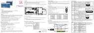
Operation5. Operation5.1 Starting UpConnect the the display/output devices through the signal output socket, see Chap. 4.7, see Chap.4.7.2, see Chap. 4.7.3, before connecting the device to the power supply and switching on the powersupply.Allow the measuring system to warm up before the first measurement or calibration for approximatelyi 15 min.5.2 Operating or Display Elements5.2.1 LED‘sLED Color FunctionETHERNETRangeLP FilterZeroRangegreenredTarget in measuring rangeMeasuring range exceededZeroPOWER/TRIG.SENSOR/CPSIGNAL OUTLP Filter 1 off Standard bandwidth activeZeroredoffred20 Hz Low-pass filter on theanalog outputs enabledZero poti in basic position(right stop)Zero poti adjusted<strong>capaNCDT</strong> <strong>6200</strong>1) LP Filter only switchable via Ethernet.Page 42
Operation5.2.2 PotiThe zero-poti on the demodulator modules is used for zero adjustment of the analog outputs.End positions on the left or right stop are marked by a slight click.The electrical zero point can be set across the whole measuring range with the “zero” potentiometer. Thestart of the measuring range (= mechanical zero point) is on the front face of the sensor.A tilted sensor or measuring object results in a reduced measuring range and zero point shifting according tothe tilting.The potentiometer is ex factory set at the right stop (maximum level).10 VSignalStandard characteristicZero offset20 mASignalStandard characteristicZero offsetRangeLP FilterZeroZeroSENSOR/CP0 VDisplacementDisplacement100 %4 mA100 %SIGNAL OUTZeroZeroDL62xx-10 V-12 mAFig. 16 Zero point shifting with zero-poti<strong>capaNCDT</strong> <strong>6200</strong>Page 43
Operation5.2.3 Change Ethernet / EtherCATFig. 17 Change Ethernet/EtherCATA switch between Ethernet and EtherCAT, is possible via a hardware switch, see Fig. 17 or via software on thebasic unit DT6230, see Chap. 7.2.If the switch is in position EN (Ethernet), always the Ethernet interface is active independent of the softwaresetting. If the switch is in position EN/EC (Ethernet/EtherCAT), then the active interface depends on thesoftware setting. To change the interface it is necessary to restart the controller.5.3 Changing Limit FrequencyThe controller operates with a limit frequency of 5 kHz (factory setting). In case that the limit frequency isreduced to 20 Hz, the output signal is filtered more efficiently and the resolution is therefore improved; at thesame time the dynamic of the system is reduced. The limit frequency can only be changed via the Ethernetinterface.<strong>capaNCDT</strong> <strong>6200</strong>Page 44
Operation5.4 TriggeringThe measuring value output on <strong>capaNCDT</strong> <strong>6200</strong> is controllable by an external electrical trigger signal or command.Here, only the digital output is affected.Triggering release by:--Trigger input (pin 3 and pin 4 on 4-pole power supplyconnector, see Chap. 4.7.2 or--Software command $GMD, see Chap. 6.4.3--U IN, HIGH ≥ 2,0 V--U IN, LOW ≤ 0,8 VFig. 18 Trigger InputThe trigger type is determined bythe command $TRGn, see Chap. 6.4.2 or--the web interface, see Chap. 6.5.6Level triggering (high level). Continuous measurement outputwith adjusted data rate, as long as the selected level is active.After that the controller stops the output of the measuringvalues.Fig. 19 Active high level trigger (UI ), relevant digital signal (D 0 )Trigger in3U trigger(TTL level,potential-free)U ID 04GND triggerI = 5 ... 45 mA100 OhmUF=appr.1 VControllertt<strong>capaNCDT</strong> <strong>6200</strong>Page 45
OperationEdge triggering. Starts measuring value output, as soon as therising edge on the trigger input is active. If trigger conditionsare met, the controller outputs a measuring value. The set datarate must be greater than the maximum trigger frequency. Iftriggering is faster than the set data rate, individual measuringvalues are transmitted twice, because internally no new measuringvalues of the AD converter are active.The duration of the pulse must be at least 5 µs.Fig. 20 Rising edge trigger (UI ), relevant digital signal (D 0 )U ID 0ttGate rising edge. Starts measuring value output with set datarate, as soon as the rising edge on the trigger input is active.Another rising edge stops the measuring value output respectivelyswitches it on again.Fig. 21 Rising edge trigger (UI ), relevant digital signal (D 0 )U ID 0ttSoftware triggering ($GMD). A measuring value is output per channel, as soon as a command is sent. Thepoint of time is not defined as accurately.No trigger is set ex factory. The controller starts the data transfer immediately after the switching on.<strong>capaNCDT</strong> <strong>6200</strong>Page 46
Operation5.5 Measurement Averaging5.5.1 IntroductionMeasurement averaging is performed before the output of measuring values via the Ethernet interfaces.Measurement averaging improves the resolution, allows masking individual interference points or “smoothes”the reading.Linearity is not affected by averaging. Averaging has no effect on measuring frequency and output rate.iThe controller is delivered ex factory without measurement averaging.5.5.2 Moving AverageThe definable number N for successive measurements (window width) is used to calculate the arithmeticaverage M movaccording to the following formula:N∑MV (k=1M mov =NFig. 22 Formula for the moving averageMV = Measuring valueN = Numberk = Continuous indexM mov= Average valueMethodEach new measured value is added, and the first (oldest) value is removed from the averaging.Example with N = 7:.... 0 1 2 3 4 5 6 7 8 gets to 2+3+4+5+6+7+8 Average value n7.... 1 2 3 4 5 6 7 8 9 gets to 3+4+5+6+7+8+97Average value n +1<strong>capaNCDT</strong> <strong>6200</strong>Page 47
Operation5.5.3 Arithmetic Average ValueThe arithmetic average value M is set and output over the selected number N of successive measuring values.MethodMeasuring values are collected and the average value is calculated consequently. This method leads to areduction of the amount of data, because an average value is output only after every Nth measuring value.Example with N = 3:.... 0 1 2 3 4 ... gets to 2+3+43Average value n.... 3 4 5 6 7 ... gets to 5+6+73Average value n + 15.5.4 MedianA median value is formed from a preselected number of measurements. For this, the incoming values aresorted after each measurement. Then, the average value is provided as the median value.If a even value is selected for the average number N, middle both measuring values are added and dividedby two.Example with N = 7:Sorted measuring value Median n= 2Sorted measuring value Median n+1= 35.5.5 Dynamic Noise RejectionThis filter removes the noise of the measurement signal completely, but keeps the original bandwidth of themeasurement signal.For that purpose the signal noise is calculated dynamically and measurement changes are only transferred, ifthey exceed this calculated noise. Thereby at a change in direction of the measurement signal small hysteresiseffects in the size of the calculated noise can occur.<strong>capaNCDT</strong> <strong>6200</strong>Page 48
Ethernet Interface6. Ethernet InterfaceYou will achieve especially high resolutions if you readout the measurements in digital form via the Ethernetinterface.For that purpose. use the web interface or a special program. MICRO-EPSILON supports you by the driverMEDAQLib, containing all commands for <strong>capaNCDT</strong> <strong>6200</strong>. You will find more details on the enclosed CD oron the Internet: www.micro-epsilon.de/software “Standard applications > MEDAQlib“.6.1 Hardware, InterfaceThe data logging of all channels is synchronous.Connect the <strong>capaNCDT</strong> <strong>6200</strong> to an available Ethernet interface at the PC. Use a crossover cable.For a connection with the <strong>capaNCDT</strong> <strong>6200</strong> you will require a defined IP address of the network interface cardinside the PC. Go to Control Panel\Network Connections. Set up, if applicable, a new LAN connection.For more information, contact your network administrator.Fig. 23 LAN connection of a PC<strong>capaNCDT</strong> <strong>6200</strong>Page 49
Ethernet InterfaceDefine the following address in the properties of the LAN connection:IP address: 169.254.168.1Subnet mask: 255.255.0.0Select Properties. Select Internet Protocol (TCP/IP) >Properties.<strong>capaNCDT</strong> <strong>6200</strong>Page 50
Ethernet Interface<strong>capaNCDT</strong> <strong>6200</strong>By default, the IP address of the controller is set to 169.254.168.150. Communication with the controller isdone on the data port 10001 for measurement transmission. A command port (Telnet, port 23) is used forsensor commands.The IP settings and the data port can be changed at any time:--by using the web browser. Enter the current IP address into the address bar. Go to the menu Settings> Digital Interfaces > Ethernet settings to set a new IP address, activate DHCP orchange the data port.--by using software commands, see Chap. 6.4.--by using the SensorFinder software.If you activate DHCP, access to the controller via a DHCP host name is possible. The host name contains thedevice name and serial number. Structure: NAME_SN e. g. DT6220_1001.Page 51
Ethernet InterfaceThe controller supports UPnP. If you use an operational system with activated UPnP client e. g. standard withWindows 7, the controller is listed in the explorer as a device automatically. This is helpful, if you do not knowthe IP address of the controller.<strong>capaNCDT</strong> <strong>6200</strong>Page 52
Ethernet Interface6.2 Data Format of Measuring ValuesAll measuring values, recorded at a time, are combined into a measuring value frame (One measuring valueper channel).Several measuring value frames are combined to a measuring value block and then transmitted together witha header as a TCP packet.All measuring values and the header are transmitted in little-endian format.<strong>capaNCDT</strong> <strong>6200</strong>Contents Size DescriptionPreamble 32 bit „MEAS“ as an ASCII textOrder number 32 bit Order number of sensor as intSerial number 32 bit Serial number of sensor as intChannels(Bit field)64 bit Bit field, which channel available. Two bits per channel are used: „00“=Channel is not available; „01“=channel available. The lowest channel is onthe most low-order bit ->Thereby determining the number of channels Npossible.Status 32 bit Is not used.Frame number M / 16 bit / One frame = one measuring value per channelbytes per frame 16 bitMeasuring valuecounter32 bit Measuring value counter (of 1st frame)Measuring valueframe 1 [numberchannels N]Measuring valueframe 2 [numberchannels N]N *32 bitN *32 bit.... ... ...Measuring valueframe M [numberchannels N]N *32 bit„Measuring values all channels, starting with the lowest channel number„Page 53
Ethernet InterfaceAll measuring values are transmitted as Int32. The measuring value resolution is 24 bits i.e only the most loworder24 bits of integer number are used. Hexadecimal range: 0 ... FFFFFF 16. Exception is the mathematicsfunction, because the result can also be greater than 24 bits.Scaling of measuring values:Digital value (Int)Measurement in µm =0xFFFFFF* Measring range in µmExample: Measuring range sensor CS2 = 2000 µm; digital value = 7FFFFF 16Measurement = 999.99 µmBy default, the measuring values are continuously output with the set data rate via the data port.However, there is also a trigger mode, with can be used to get the individual measuring values, see Chap.6.4.2.6.3 SettingsOperating modes:--Continuous transmission with fixed data frequency--Trigger mode (recall hardware trigger input or individual measuring values, see Chap. 5.4.Data rate:It is possible to adjust different data rates between 2.5 Sa/s and 3.9 kSa/s. The data rate applies to all channels.Filter/Measuring value averaging:The following filters are selectable:--Moving average--Arithmetic average (only each n th value will be output)--Median--Dynamic Noise RejectionThe setting for the averaging applies to all channels.<strong>capaNCDT</strong> <strong>6200</strong>Page 54
Ethernet InterfaceLinearization Options:--Offset correction--2-point-linearization--3-point-linearization--5-point-linearization--10-point-linearizationUp to 10 linearization points can be measured for each channel. These are at 10 %, 20 %, 30 %, 40 %, 50 %,60 %, 70 %, 80 %, 90 % and 100 % of the measurement range. That means, for example, that the sensor isadjusted to 10 % of the measurement range. This linearization point (= actual measurement at this point) isthen measured and a correction curve is calculated so that the linearized measured value corresponds to thetarget measurement value.Only the measurement value at 10 % of the measurement range is used for the correctionof the start of the measurement range.The correction curve for the 2-point-linearization uses data points at 10 % and 90 % of the measurementrange.The two correction curves for the 3-point-linearization use restart points at 10 % and 50 %, 50 % and 90 % ofthe measurement range.The four correction curves for the 5-point-linearization use data points at 10 % and 30 % , 30 % and 50 %,50 % and 70 %, 70 % and 90 % of the measurement range.The nine correction curves for the 10-point-linearization use data points at 10 %, 20 %, 30 %, 40 %, 50 %,60 %, 70 %, 80 %, 90 % and 100 % of the measurement range.The linearization function allows an individual adjustment--of the start of the measurement range,--slope of the characteristic curve (Gain) and--linearity.<strong>capaNCDT</strong> <strong>6200</strong>Page 55
Ethernet Interface96000 10.4 Sa/s64000 15.6 Sa/s38400 26 Sa/s32000 31.3 Sa/s19200 52.1 Sa/s16000 62.5 Sa/s9600 104.2 Sa/s1920 520.8 Sa/s960 1041.7 Sa/s480 2083.3 Sa/s256 3906.3 Sa/sRequest sample timeCommand $STI?Response $STI?nOK<strong>capaNCDT</strong> <strong>6200</strong>Page 58
Ethernet Interface6.4.2 Trigger Mode (TRG)There are three possible settings regarding the trigger input, see Chap. 5.4.Irrespective of the trigger mode set, a single measured value per channel can be called up by means ofa software command, see Chap. 5.5.3. If the trigger mode is turned off, the <strong>capaNCDT</strong> <strong>6200</strong> will send themeasurement values without interruption and with the adjusted data rate.TRGCommand $TRGnResponse $TRGnOKIndexn = 0: Continuous transmission (default setting)n = 1: Triggermode 1 (rising edge)n = 2: Triggermode 2 (high level)n = 3: Triggermode 3 (gate rising edge)? = Request trigger modeRequest Trigger modeCommand $TRG?Response $TRG?nOK6.4.3 Get Measured Data (GMD)In the trigger mode, one measuring value is transmitted per channel.GMDCommand $GMDResponse $GMDOK + Measuring value in binary mode (format as inoperating mode “continuous transmission”) via data port<strong>capaNCDT</strong> <strong>6200</strong>Page 59
Ethernet Interface6.4.4 Filter, Averaging Type (AVT)Mode of measurement averagingAVTCommand $AVTnResponse $AVTnOKIndexn = 0: No averaging (Default setting)n = 1: Moving averagen = 2: Arithmetic average (outputs only each nth measuring value)n = 3: Mediann = 4: Dynamic noise rejection? = Request averaging typeRequest averaging typeCommand $AVT?Response $AVT?nOK6.4.5 Filter, Averaging Number (AVN)Number of measuring values used to calculate the average (adjustable from 2 … 8)AVNCommand $AVNnResponse $AVNnOKIndex n = 2 ... 8? = Request averaging numberRequest averaging numberCommand $AVN?Response $AVN?nOK<strong>capaNCDT</strong> <strong>6200</strong>Page 60
Ethernet Interface6.4.6 Channel Status (CHS)Specifies in increasing order in which channels there is a module. (0 = no channel available, 1 = channelavailable, 2 = math function is output on this channel)CHSCommand $CHSResponse $CHS1,0,2,1OK(Example: Channel 1,3,4 available, channel 3with math function)6.4.7 Mode of Linearization (LIN)Specifies the linearization type for each channel.The linearization type can be set for each channel. The index m stands for channel number, the index n forthe linearization type.LINCommand $LINm:n (for example: $LIN4:2 = 2-point-linearizationfor channel 4)Response $LINm:nOKIndex m(Channel number)1 … 4Index n (linearizationmode) 1 = Start of measuring range0 = no linearization (default setting)2 = 2-point-linearization3 = 3-point-linearization4 = 5-point-linearization5 = 10-point-linearizationRequest linearization modeCommand $LIN?Response $LIN?n,n,n,nOK (n stands for the linearization type)<strong>capaNCDT</strong> <strong>6200</strong>Page 61
Ethernet Interface6.4.8 Set Linearization Point (SLP)Sets a linearization point.Place the sensor or the target in the corresponding position. After the command has been received, thecurrent measuring value will be recorded at this position as a linearization point and thus the constants arerecalculated for the linearization.SLPCommand $SLPm:n (for example: $LIN4:3 = linearization point at30 % of channel 4)Response $SLPm:nOKIndex m1 ... 4(channel number)Index n (linearizationpoint) 1 = linearization point at 10 % of the measuring rangen (linearization point):2 = linearization point at 20 % of the measuring range3 = linearization point at 30 % of the measuring range4 = linearization point at 40 % of the measuring range5 = linearization point at 50 % of the measuring range6 = linearization point at 60 % of the measuring range7 = linearization point at 70 % of the measuring range8 = linearization point at 80 % of the measuring range9 = linearization point at 90 % of the measuring range10 = linearization point at 100 % of the measuring range<strong>capaNCDT</strong> <strong>6200</strong>Page 62
Ethernet Interface<strong>capaNCDT</strong> <strong>6200</strong>6.4.9 Get Linearization Point (GLP)Reads out the linearization point.The value is output hex format.GLPCommand $GLPm:n (for example: $GLP4:3 = linearization pointat 30 % of channel 4)Response $GLPm:n,……OK (for example $GLP5:3,A034C9OK)Index m (channel number): 1…4n (linearization point):1 = linearization point at 10 % of measuring range2 = linearization point at 20 % of measuring range3 = linearization point at 30 % of measuring range4 = linearization point at 40 % of measuring range5 = linearization point at 50 % of measuring range6 = linearization point at 60 % of measuring range7 = linearization point at 70 % of measuring range8 = linearization point at 80 % of measuring range9 = linearization point at 90 % of measuring range10 = linearization point at 100 % of measuring range6.4.10 Status (STS)Reads all settings at once.The individual parameters are separated by a semicolon. The structure of the respective responses correspondsto those of the individual requests.CommandResponseSTS$STS$STSSTIn;AVTn;AVNn;CHS…;TRG.OKPage 63
Ethernet Interface6.4.11 Version (VER)Requesting the current software version including date.VERCommand $VERResponse $VERDT<strong>6200</strong>;V0.9a;25.10.2007OK6.4.12 Set Mathematic Function (SMF)Sets a math function on a certain channel.SMFCommand $SMFm:Offset,Factor1,Factor2,Factor3,Factor4Response$SMFm:Offset,Factor1,Factor2,Factor3,Factor4,OKIndex m: 1…4(Channel number)OffsetFactor1, ..., Factor4If a channel is selected, which is alreadyreserved by electronics, the result of the mathfunction is now transmitted instead of the measuredvalue.24 bit offset value with prefix in hex format,at which 21 bit comply with 100 % measuredvalue.Numbers exceeding 21 bit are thereforegreater (for example +3FFFF = complies with200 % of the measured value).Multiplication factors (including prefix), withwhich the measured values of channel 1 upto 8 are multiplied. The range of values of -9.9up to +9.9 with a decimal place. Structure offactors: Prefix and a one-digit number with adecimal place, example +3.4<strong>capaNCDT</strong> <strong>6200</strong>Page 64
Ethernet InterfaceExample: $SMF2:+1FFFFF,+1.0,+0.0,+0.0,-0.3On channel 2 the sequent math function is output:100 % Offset + 1 * channel 1 - 0.3 * channel 4Sensor 1MR1 mmTargetSensor 2MR 1 mm2 mmFig. 25 Example for thickness measurement of a target with two capacitive sensorsFollowing math function is required for the above adjustment for thickness measurement of the target.Target thickness = +200 % offset (equates to 2 mm) – 1 * channel 1 – 1 * channel 2Required command:$SMF3:+3FFFFF,-1.0,-1.0,+0.0,+0.0i3 measured values can be allocated together at most, the different factors have to be +0.0 each.If a math function is set on a channel, the channel status changes onto 2.<strong>capaNCDT</strong> <strong>6200</strong>Page 65
Ethernet Interface6.4.13 Get Mathematic Function (GMF)Reads out the math function of a channel.GMFCommand $GMFmResponse $GMFm:Offset,Factor1,Factor2,Factor3,Factor4OKIndex m: 1…4(Channel number)OffsetFactor1, ..., Factor4If a channel is selected, which is already reservedby electronics, the result of the math function is nowtransmitted instead of the measured value.24 bit offset value with prefix in hex format, at which21 bit comply with 100 % measured value.Numbers exceeding 21 bit are therefore greater (forexample +3FFFF = complies with 200 % of the measuredvalue).Multiplication factors (including prefix), with which themeasured values of channel 1 up to 4 are multiplied.The range of values of -9.9 up to +9.9 with a decimalplace. Structure of factors: Prefix and a one-digit numberwith a decimal place. Example +3.4.6.4.14 Clear Mathematic Function (CMF)Deletes the math function on a channel.CMFCommand $CMFmResponse $CMFmOKIndexm: 1…4 (Channel number)<strong>capaNCDT</strong> <strong>6200</strong>Page 66
Ethernet Interface6.4.15 Ethernet Settings (IPS)Changes the IP settings of the controller.CommandExampleResponseIndexIPS$IPSm,,
Ethernet Interface6.4.17 Query Data Port (GDP)Queries the port number of the data port.Command $GDPResponse$GDPOKExample: $GDP10001OK6.4.18 Set Data Port (SDP)Sets the port number of the data port. Range: 1024 ...65535.Command $SDP Example: $SDP10001OKResponse $SDPOK6.4.19 Access Channel Informations (CHI)Reads channel-specific informations (e.g. serial number of the display board).Command $CHlmResponse $CHlm:ANO...,NAM...,SNO...,OFS...,RNG...UNT...OK>CRLFIndexm (Channel number): 1 - 4ANO = Article numberNAM = NameSNO = Serial numberOFS = Measuring range offsetRNG = Measuring rangeUNT = Unit of measuring range (e.g. µm)<strong>capaNCDT</strong> <strong>6200</strong>Page 68
Ethernet Interface6.4.20 Access Controller Informations (COI)Reads informations of the controller (e.g. serial number).CommandResponseIndex$COI$COIANO...,NAM...,SNO...,OPT...,VER...OKANO = Article numberNAM = NameSNO = Serial numberOPT = OptionVER = Software version6.4.21 Login for Web Interface (LGI)Changes the user level for the web interface on professional.CommandResponseIndex$LGl$LGlCRLFPassword = Password of the device. When delivered, no password is assigned.The field can remain empty.6.4.22 Logout for Web Interface (LGO)Changes the user level for the web interface on user.CommandResponse$LGO$LGOOK<strong>capaNCDT</strong> <strong>6200</strong>Page 69
Ethernet Interface6.4.23 Change Password (PWD)Changes the password of the device (required for the web interface and the SensorFinder).Command $PWD,,Response$PWD,,OKA password can be from 0-16 characters and must contain only letters andnumbers. When delivered, no password is assigned. The field can remainempty/blank.6.4.24 Change Language for the Web Interface (LNG)Changes the language of the web interface.Command $LNGnResponse $LNGnOKIndex0 = System1 = English2 = German6.4.25 Write Measuring Range Information in Channel (MRA)Changes the measuring range information of a channel (e.g. in case of a sensor change). This information ise.g. required for the correct scaling of the measuring values in the web interface. The value is specified in μm.This is only an information value, what means, the actual measuring range of a sensor is not changed bychanging the value.$MRAm: (Example: $MRA2:2000 sets the measuringrange of channel 2 to 2000 µm)CommandResponse $MRAm:OK
Ethernet Interface6.4.26 Set Analog Filter (ALP)Enables/Disables a low pass filter with 20 Hz limit frequency on analog outputCommand $ALPnResponse $ALPnOK0 = Low pass filter not activeIndex1 = Low pass filter is activeRequest $ALP?Response $ALP?nOK6.4.27 Default Messages--Unknown command: (ECHO) + $UNKNOWN COMMAND--Wrong parameter after command: (ECHO) + $WRONG PARAMETER--Timeout (approximately 15 s after last input) (ECHO) + $TIMEOUT--Wrong password: $WRONG PASSWORD<strong>capaNCDT</strong> <strong>6200</strong>Page 71
Ethernet Interface6.5 Operation Using EthernetDynamic web pages are generated in the controller which contain the current settings of the controller andthe peripherals. Operation is only possible while there is an Ethernet connection to the controller.6.5.1 RequirementsYou need a web browser (e.g. Mozilla Firefox 3 or Internet Explorer 8) on a PC with a network connection.To support a basic first commissioning of the controller, the controller is set to a direct connection.If you have configured your browser to access the internet via a proxy server, in the browser settings you willneed to add the IP address of the controller to the list of addresses which should not be routed through theproxy server. The MAC address of the unit can be found on the nameplate of the controller.“Java” and “Javascript” must be enabled and up-to-date in the browser so that measurement results can bedisplayed graphically. The PC requires Java (Version 6, update 12 or later). Source: www.java.com > “JRE6Update 12”.<strong>capaNCDT</strong> <strong>6200</strong>Page 72
Ethernet InterfaceDirect connection to PC, controller with static IP (Factory setting) NetworkPC with static IP PC with DHCP Controller with dynamic IP, PC with DHCPConnect the controller to a PC using a direct Ethernet connection (LAN).Use a LAN cable with RJ-45 connectors for this.Now start the SensorFinder program. Youwill find this program on the provided CD.Click the button Start SensorScan. Select the designated controllerfrom the list. In order to change theaddress settings, click the button OpenIP-Config.••Address type: static IP address••IP address: 169.254.168.150 1••Subnet mask: 255.255.0.0Click the button Transfer IP Settingsto Sensor, to transmit thechanges to the controller.Click the button Open Web Interface,to connect the controller with yourdefault browser.1) Requires that the LAN connection on thePC uses, for example, the following IP address:169.254.168.1.Wait until Windows has establisheda network connection(Connection with limited connectivity).Now start the Sensor-Finder program. You willfind this program on theprovided CD.Click the button StartSensor Scan. Selectthe designated controllerfrom the list.Click the button OpenWeb Interface toconnect the controller withyour default browser.Interactive web pages for setting the controller and peripherals are now shown in the web browser.Connect the controller to a switch using a directEthernet connection (LAN). Use a LAN cablewith RJ-45 connectors for this.Enter the controller in the DHCP / register thecontroller in your IT department.The controller gets assigned an IP address from yourDHCP server. You can check this IP address with theSensorFinder program.Now start the SensorFinder program.You will find this program on the provided CD.Click the button Start Sensor Scan. Selectthe designated controller from the list.Click the button Open Web Interface, toconnect the controller with your default browser.Alternatively: If DHCP is used and the DHCP server islinked to the DNS server, access to the controller viaa host name of the structure “DT6230_”is possible.Start a web browser on your PC. To achieve acontroller with the serial number “01234567”,type in the address bar on your browser“DT6230_01234567”.<strong>capaNCDT</strong> <strong>6200</strong>Page 73
Ethernet Interface6.5.2 Access via Web InterfaceUse the upper navigation bar toaccess additional features (e. g.Settings).All settings on the web page areapplied immediately in the controllerafter pressing the Submit button.Fig. 26 First interactive web page after calling the IP addressParallel operation with web interface and Telnet commands is is possible; the last setting applies.The appearance of the web pages may vary depending on functions and peripherals. Each page containsparameter descriptions and tips on completing the controller.<strong>capaNCDT</strong> <strong>6200</strong>Page 74
Ethernet InterfaceOperating Menu, Set Controller ParameterPreliminary Notes to the SettingsYou can program the <strong>capaNCDT</strong> <strong>6200</strong> at the same time in two different kinds:--Using a web browser via the sensor web interface--With ASCII command set and terminal program via Ethernet (Telnet)Login, Changing User LevelAssigning passwords prevents unauthorized changes to controller settings. Password protection is not enabledas a factory setting. After the controller has been configured, you should enable password protection.iA firmware update will not change the custom password.User can do the following:UserProfessionalPassword required no yesView settings yes yesChange settings, change password no yesStart measuring yes yesScale graphs yes yesFig. 27 Permissions within the user hierarchyLoginLogged in asPasswordUserSubmitEnter the password into the Passwordbox and click Submit toconfirm.To change to user mode, click theLogoff button.Fig. 28 Changing to professional level<strong>capaNCDT</strong> <strong>6200</strong>Page 75
Ethernet InterfaceIn professional mode, you can use the change password features to assign a custom password.Password Value All passwords are case-sensitive. Numbers are allowed, but specialcharacters are not permittedUser level at restart User /ProfessionalDefines the user level that is enabled when the sensor starts the nexttime. MICRO-EPSILON recommend to select User level.With the first-time assignment of a password the Old Password field remains free.6.5.3 Measuring RangesThe measuring ranges of the connected sensors must be entered <strong>manual</strong>ly. Do not forget to enter the newrange after changing a sensor.Data channel 1 / 2 / 3 / 4 Value Value range 0 ... 1000000 µm<strong>capaNCDT</strong> <strong>6200</strong>Page 76
Ethernet Interface6.5.4 LinearizationA linearization of a measuring channel (physical demodulator module) may be necessary, if, for example, thetarget geometry is changed. Selection of a linearization type depends on how many data points the correctioncurve should use.iThe measuring device requires a run-in period of approximately 15 minutes.Measuring1 / 2 / 3 / 4 Linearization type Offset / 2-point / 3-point / 5-point / 10-point / OffchannelThe sequence, with that the linearization points are measured, doesn‘t play a role.Example: Procedure for a 3 point linearization:Select the designated measuring channel.Select a 3-point linearization type.Adjust the target to 10 % of the measuring range to the sensor.Target010 %Measuring rangeSensorClick on the Submit button in web interface in the line 10 %<strong>capaNCDT</strong> <strong>6200</strong>Page 77
Ethernet InterfaceAdjust the target to 50 % of the measuring range to the sensor.Target050 %MeasuringrangeSensorClick on the Submit button in web interface in the line 50 %Adjust the target to 90 % of the measuring range to the sensor.Target0Measuring range 90 %SensorClick on the Submit button in web interface in the line 90 %The program will calculate the correction curve from the three data points.<strong>capaNCDT</strong> <strong>6200</strong>Page 78
Ethernet Interface6.5.5 Math FunctionsThis function enables the scaling of a measuring channel and the mathematical combination of individualchannels.Formula: Data channel = Offset + factor measuring channel 1 + factor measuring channel 2 + factor measuringchannel 3 + factor measuring channel 4.Data channel = digital valuesMeasuring channel = analog value of a demodulator moduleData channel 1 / 2 / 3 / 4Offset Value Value range ±8-point MR max.Factor measuring channel Value Value range -9,9 ... +9,96.5.6 Trigger ModeThis menu item determines the trigger behavior. The triggering is released by an external electrical signal, seeChap. 4.7.2 or by the command $ GMD, see Chap. 6.4.3.If the trigger mode is turned off, the <strong>capaNCDT</strong> <strong>6200</strong> will send the measuring values without interruption andwith the adjusted data rate.Trigger modeRising edgeHigh levelGate rising edgeOff6.5.7 Data RateA measuring value is output per edge.Level triggering. Measuring value output, as long as the level is active.Starts resp. stops the measuring value output alternatively.Controller sends measuring values continuously.Data Rate2.6 / 5.21 / 10.42 / 15.63 / 26.04 / 31.25 / 52.08 / 62.5 /104.2 / 520.83 / 1041.67 / 2083.33 / 3906.25 Sa/sInstructs the sensor about thefrequency, with which data areoutput via the Ethernet interface.<strong>capaNCDT</strong> <strong>6200</strong>Page 79
Ethernet Interface6.5.8 Filter, AveragingAverage typeOffMovingArithmeticMedianValueValueValueDynamic noise rejectionValue range 2 / 3/ 4 / 5 / 6 / 7 / 8Designation of averaging type. Averagingnumber indicates, abouthow many current measuringvalues should be averaged in thecontroller, before a new measuringvalue is output.It is recommended, to use averaging for statical measuring or slowly changing measuring values. An averagingreduces noise or suppresses distortions in measuring values.6.5.9 Analog Low Pass FilterFilter active / inactive Switches the deep pass filter with 20 Hz limit frequency on analog output6.5.10 Digital InterfacesEthernetSettingsEthernet/EtherCATIP settings Address type static IP address/ DHCPIP address ValueSubnet mask ValueDefault Gateway ValueDHCP Host Name ValuePort settings Data port ValueMAC address ValueUUIDValueOperating mode Ethernet / EtherCATafter startValues for IP address / Gateway/ Subnet mask. For static IP addressonly<strong>capaNCDT</strong> <strong>6200</strong>Page 80
EtherCAT Interface7. EtherCAT Interface7.1 IntroductionThe EtherCAT interface allows a fast transfer of measured values. The controller supportsCANopen over EtherCAT (CoE).Service Data Objects SDO: All parameters of the controller can thus be read or modified.Process Data Objects PDO: A PDO telegram is used for real-time transmission of measured values. Individualobjects are not addressed. The content of the previously selected data is transmitted.The displacement values are transmitted as 32 bit Float values.7.2 Change InterfaceYou can not change directly to the EtherCAT interface through the web interface or command. Restart yourcontroller to do this. Keep in mind also that the setting of the EtherCAT switch is in the correct position, seeFig. 29, see Chap. 5.2.3.Switch positionEN (Ethernet)MeaningRegardless to thesoftware setting alwaysthe Ethernet interfaceis active.EN/EC(Ethernet/EtherCAT)Active interface, whichis set via the web interfaceor command.Fig. 29 Switch to change the interface<strong>capaNCDT</strong> <strong>6200</strong>Page 81
MeasurementA change from the EtherCAT interface back to the Ethernet interface is possible with the hardware switch onthe DT6230 basic unit or via the corresponding CoE Object. In both cases, then a restart of the controller isrequired.To integrate the EtherCAT interface e.g. within TwinCAT an ESI-file is supplied.You will find further instructions in the appendix, see Chap. A 6.8. MeasurementWith the <strong>capaNCDT</strong> either the deflection or the compensation method of measurement can be applied.--Deflection method for fast events and tolerance monitoring:Put the zero point in the centre of the measuring range, the output signal is then in proportion to the distance.Fast events are displayed on a suitable external recorder (oscilloscope, recorder, transient recorder).--Compensation method for constant or slowly changing distances.Compensation is carried out with the “zero” potentiometer until the output signal is 0 Volt. Sensitivity is notaffected by doing this.<strong>capaNCDT</strong> <strong>6200</strong>Page 82
Operation and Maintenance9. Operation and MaintenancePlease take care of the following:Make sure that the sensor surface is always clean.Switch off the power supply before cleaning.Clean with a damp cloth; then rub the sensor surface dry.Changing the target or very long operating times can lead to slight reductions in the operating quality (longterm errors). These can be eliminated by recalibration.Disconnect the power supply before touching the sensor surface.> > Static discharge> > Danger of injuryIn the event of a defect in the controller, thesensor or the sensor cable, the parts concernedmust be sent back for repair or replacement. Inthe case of faults the cause of which is not clearlyidentifiable, the whole measuring system must besent back for repair or replacement toMICRO-EPSILON MESSTECHNIKGmbH & Co. KGKönigbacher Straße 1594496 Ortenburg / GermanyTel. +49 (0) 8542 / 168-0Fax +49 (0) 8542 / 168-90info@micro-epsilon.dewww.micro-epsilon.com<strong>capaNCDT</strong> <strong>6200</strong>Page 83
Warranty10. WarrantyAll components of the device have been checked and tested for perfect function in the factory. In the unlikelyevent that errors should occur despite our thorough quality control, this should be reported immediately toMICRO-EPSILON.The warranty period lasts 12 months following the day of shipment. Defective parts, except wear parts, will berepaired or replaced free of charge within this period if you return the device free of cost to MICRO-EPSILON.This warranty does not apply to damage resulting from abuse of the equipment and devices, from forcefulhandling or installation of the devices or from repair or modifications performed by third parties.No other claims, except as warranted, are accepted.MICRO-EPSILON will specifically not be responsible for eventual consequential damage. The terms of thepurchasing contract apply in full.MICRO-EPSILON always strives to supply the customers with the finest and most advanced equipment.Development and refinement is therefore performed continuously and the right to design changes withoutprior notice is accordingly reserved.For translations in other languages, the data and statements in the German language operation <strong>manual</strong> areto be taken as authoritative.11. Decommissioning, DisposalDisconnect the cable for electrical power and output signal on the controller.Disconnect the cable between sensor and controller.The <strong>capaNCDT</strong> <strong>6200</strong> is produced according to the directive 2011/65/EU, „RoHS“.Do the disposal according to the legal regulations (see directive 2002/96/EC).<strong>capaNCDT</strong> <strong>6200</strong>Page 84
Appendix| Accessories, ServiceAppendixA 1Accessories, ServiceA 1.1Conversion KitThe conversion kit is contained in the scope of supply, see Chap. 3.1.Ground terminalø 4,3 mm(.17.3 dia.)Ground connectionMounting clamps for mountingon DIN-rail20 x 0.8 mm/CK75G hardened/platedMounting clamps formounting on DIN-rail<strong>capaNCDT</strong> <strong>6200</strong>Page 85
Appendix| Accessories, ServiceMounting plate Aluminum /powder-coatedPlugging off assistance for connectorR53(.12)15( 95)50 (1.97)135 °R28(.31)2(.08)10(.39)0 7(.03)Dimensions in mm (inches), not to scaleFurther more, the conversion kit contains sleeve nuts, threaded rods in different lengths and screws.20( 79)<strong>capaNCDT</strong> <strong>6200</strong>Page 86
Appendix| Accessories, ServiceA 1.3 PC<strong>6200</strong>-3/4The PC<strong>6200</strong>-3/4 is contained in the scope of supply, see Chap. 3.1.PC<strong>6200</strong>-3/4Power supply and trigger cable, 3 m longA 1.4Optional AccessoriesMC2.5<strong>Micro</strong>meter calibration fixture,setting range 0 - 2.5 mm, reading 0.1 μm,for sensors CS005 to CS2MC25DDigital micrometer calibration fixture,setting range 0 - 25 mm, adjustable zeropoint for all sensors<strong>capaNCDT</strong> <strong>6200</strong>Page 87
Appendix| Accessories, ServiceSWH.OS.650.CTMSV34M10x0,752Vacuum feed through,Max. leak rate 1x10e- 7 mbar · l s -1Compatible with connector type BSW12ø8,8ø149max. 17<strong>capaNCDT</strong> <strong>6200</strong>Page 88
Appendix| Accessories, ServiceUHV/Bø13.50h6M9x0.51.75(.07)25 (.98)ø9.4 (.37 dia.)SW11Vacuum feed through triax weldableMax. leak rate 1x10e- 9 mbar · l s -1Compatible with connector type B25 (.98)13.5 (.53)6(.24)Vacuum feed through triax with CF16flangeMax. leak rate 1x10e-9 mbar · l s -1Compatible with connector type Bø34 (1.34)(Standard flange CF16)M9x0.5ø9.4(.37)Knit lineø13.50h6M9x0.51.75(.07)25 (.98)ø9.4 (.37 dia.)SW11Vacuum feed through triax screwableMax. leak rate 1x10e-9 mbar · l s -1Compatible with connector type BAll vacuum feed throughs are compatible to the connectors type B, see Chap. 4.3.<strong>capaNCDT</strong> <strong>6200</strong>Page 89
Appendix| Accessories, ServiceSCACx/4Signal output cable analog, x m long(necessarily for multi-channel operation)SC6000-xSynchronization cablePS2020Power supply for mounting on DIN-railinput 230 VAC (115 VAC)output 24 VDC / 2.5 A;L/W/H 120 x 120 x 40 mmA 1.5 ServiceFunction and linearity check-out, inclusive 11-point protocol with grafic and post-calibration.<strong>capaNCDT</strong> <strong>6200</strong>Page 90
Appendix| Factory SettingA 2Factory SettingAnalog:Digital:--Zero-poti = Off (right-stop) --Data rate = 3906 Sa/s--LP filter 20 Hz = Off --Filter = Off--Linearization = Off--Trigger mode = Off--Math functions = Off--IP address = Static IP(169.254.168.150)--Data port = 10001<strong>capaNCDT</strong> <strong>6200</strong>Page 91
θθθAppendix| Tilt Angle Influence on the Capacitive SensorA 3Tilt Angle Influence on the Capacitive SensorMeasurement error [‰ MR]0-1-2-3-4-5-6-7-8-9-10TargetSensorCS02CS1CS100 0.1 0.2 0.3 0.4 0,5 0.6 0.7 0.8 0.9 1Angle [°]Measurement error [‰ MR]0-1-2-3-4-5-6-7-8-9-10TargetSensorCS1CS02CS100 0.1 0.2 0.3 0.4 0.5 0.6 0.7 0.8 0.9 1Angle [°]Fig. 30 Example of measuring range deviation in thecase of a sensor distance of 10 % of the measuringrangeFig. 31 Example of measuring range deviation in thecase of a sensor distance of 50 % of the measuringrangeMeasurement error [‰ MR]0-1-2-3-4-5-6-7-8-9-10TargetSensorCS1CS02CS100 0.1 0.2 0.3 0.4 0.5 0.6 0.7 0.8 0.9 1Angle [°]iFigures give an influence example shown onthe sensors CS02/CS1 and CS10 in the caseof different sensor distances to the target. Asthis results from internal simulations and calculations,please request for detailed information.Fig. 32 Example of measuring range deviation in thecase of a sensor distance of 100 % of the measuringrange<strong>capaNCDT</strong> <strong>6200</strong>Page 92
Appendix| Measurement on Narrow TargetsA 4Measurement on Narrow Targets50 %50 %Signa change [% of MR]45 %40 %35 %30 %25 %20 %15 %10 %5 %0 %03 mm4 mm6 mm8 mm0.5 1 1.5 2 2.5 3Target dispacement perpendicular to the sensor axis [mm]Signa change [% of MR]45 %40 %35 %30 %25 %20 %15 %10 %5 %0 %03 mm4 mm6 mm8 mm0.5 1 1.5 2 2.5Target dispacement perpendicular to the sensor axis [mm]3Fig. 33 Example of measuring range deviation in thecase of a sensor distance of 10 % of the measuringrangeFig. 34 Example of measuring range deviation in thecase of a sensor distance of 50 % of the measuringrange50 %Signa change [% of MR]45 %40 %35 %30 %25 %20 %15 %10 %5 %0 %03 mm4 mm6 mm8 mm0.5 1 1.5 2 2.5Target dispacement perpendicular to the sensor axis [mm]3yy >8 mmzz constantxMovementin x-directionFig. 35 Example of measuring range deviation in thecase of a sensor distance of 100 % of the measuringrangeFig. 36 Signal change in the case of displacement ofthin targets in the opposite direction to the measurementdirection<strong>capaNCDT</strong> <strong>6200</strong>Page 93
Appendix| Measurements on Balls and ShaftsiFigures give an influence example shown on the sensors CS05 in the case of different sensor distancesto the target as well as target widths. As this results from internal simulations and calculations, pleaserequest for detailed information.A 5Measurements on Balls and ShaftsRelative deviation [% of MR]16.0%14.0%12.0%10.0%8.0%6.0%4.0%Ball-Ø30 mm CS1Ball-Ø30 mm CS02Ball-Ø40 mm CS1Ball-Ø40 mm CS02Relative deviation [% of MR]8,0%7.0%6.0%5.0%4.0%3.0%2.0%Cylinder Ø30 mm CS1Cylinder Ø40 mm CS1Cylinder Ø30 mm CS02Cylinder Ø40 mm CS022.0%1.0%0.0%10 % 20 % 30 % 40 % 50 % 60 % 70 % 80 % 90 % 100 %Target distance (inner width), [% of MR]0.0%10 % 20 % 30 % 40 % 50 % 60 % 70 % 80 % 90 % 100 %Target distance (inner width), [% of MR]Fig. 37 Measuring value deviation in the case ofmeasurement on ball-shaped targetsiFig. 38 Measuring value deviation in the case ofmeasurement on cylindrical targetsFigures give an influence example shown on the sensors CS05 and CS1 in the case of different sensordistances to the target as well as target diameters. As this results from internal simulations and calculations,please request for detailed information.<strong>capaNCDT</strong> <strong>6200</strong>Page 94
Appendix| EtherCAT DocumentationA 6EtherCAT DocumentationEtherCAT® is, from the Ethernet viewpoint, a single, large Ethernet station that transmits and receives Ethernettelegrams. Such an EtherCAT system consists of an EtherCAT master and up to 65535 EtherCAT slaves.Master and slaves communicate via a standard Ethernet wiring. On-the-fly processing hardware is used ineach slave. The incoming Ethernet frames are directly processed by the hardware. Relevant data are extractedor added from the frame. The frame is subsequently forwarded to the next EtherCAT® slave device.The completely processed frame is sent back from the last slave device. Various protocols can be used in theapplication level. CANopen over EtherCAT technology (CoE) is supported here. In the CANopen protocol, anobject tree with Service Data Objects (SDO) and Process Data Objects (PDO) is used to manage the data.Further information can be obtained from ® Technology Group (www.ethercat.org) or Beckhoff GmbH, (www.beckhoff.com).A 6.1 PreambleA 6.1.1 Structure of EtherCAT®-FramesThe transfer of data occurs in Ethernet frames with a special Ether type (0x88A4). Such an EtherCAT® frameconsists of one or several EtherCAT® telegrams, each of which is addressed to individual slaves / storageareas. The telegrams are either transmitted directly in the data area of the Ethernet frame or in the data areaof the UDP datagram. An EtherCAT® telegram consists of an EtherCAT® header, the data area and the workcounter (WC). The work counter is incremented by each addressed EtherCAT® slave that exchanged the correspondingdata.Ethernet frame 0x88A4Destination Source EtherType Frame header 1. EtherCAT datagram 2. EtherCAT datagram ... Ethernet-CRCORDestination Source EtherType IP header UDP header Frame header 1. EtherCAT datagram 2. EtherCAT datagram ... Ethernet-CRCUDP/IP 0x88A4Length(11 bit)Fig. 39 Setup of EtherCAT framesResolution(1 bit)Type(4 bit)EtherCAT header(10 byte)Data(min 32 byte)Working counter(2 byte)<strong>capaNCDT</strong> <strong>6200</strong>Page 95
Appendix| EtherCAT DocumentationA 6.1.2 EtherCAT® ServicesIn EtherCAT® services for the reading and writing of data are specified in the physical memory of the slavehardware. The following EtherCAT® services are supported by the slave hardware:--APRD (Autoincrement physical read, Reading of a physical area with auto-increment addressing)--APWR (Autoincrement physical write, Writing of a physical area with auto-increment addressing)--APRW (Autoincrement physical read write, Reading and writing of a physical area with auto-increment addressing)--FPRD (Configured address read, Reading of a physical area with fixed addressing)--FPWR (Configured address write, Writing of a physical area with fixed addressing)--FPRW (Configured address read write, Reading and writing of a physical area with fixed addressing)--BRD (Broadcast Read, Broadcast Reading of a physical area for all slaves)--BWR (Broadcast Write, Broadcast Writing of a physical area for all slaves)--LRD (Logical read, Reading of a logical storage area)--LWR (Logical write, Writing of a logical storage area)--LRW (Logical read write, Reading and writing of a logical storage area)--ARMW (Auto increment physical read multiple write, Reading of a physical area with auto-increment addressing,multiple writing)--FRMW (Configured address read multiple write, Reading of a physical area with fixed addressing, multiplewriting)<strong>capaNCDT</strong> <strong>6200</strong>Page 96
Appendix| EtherCAT DocumentationA 6.1.3 Addressing and FMMUsIn order to address a slave in the EtherCAT® system, various methods from the master can be used. TheDT6230 supports as full slave:--Position addressingThe slave device is addressed via its physical position in the EtherCAT® segment.The services used for this are APRD, APWR, APRW.--Node addressingThe slave device is addressed via a configured node address, which was assigned by the master duringthe commissioning phase.The services used for this are FPRD, FPWR and FPRW.--Logical addressingThe slaves are not addressed individually; instead, a segment of the segment-wide logical 4-GB address isaddressed. This segment can be used by a number of slaves.The services used for this are LRD, LWR and LRW.The local assignment of physical slave memory addresses and logical segment-wide addresses is implementedvia the field bus Memory Management Units (FMMUs). The configuration of the slave FMMUs isimplemented by the master. The FMMU configuration contains a start address of the physical memory in theslave, a logical start address in the global address space, length and type of the data, as well as the direction(input or output) of the process data.A 6.1.4 Sync ManagerSync Managers serve the data consistency during the data exchange between EtherCAT® master andslaves. Each Sync Manager channel defines an area of the application memory. The DT6230 has four channels:--Sync-Manager-Channel 0: Sync Manager 0 is used for mailbox write transfers (mailbox from master toslave).--Sync-Manager-Channel 1: Sync Manager 1 is used for mailbox read transfers (mailbox from slave to master).--Sync-Manager-Channel 2: Sync Manager 2 is usually used for process output data. Not used in the sensor.--Sync-Manager-Channel 3: Sync Manager 3 is used for process input data. It contains the Tx PDOs that arespecified by the PDO assignment object 0x1C13 (hex.).<strong>capaNCDT</strong> <strong>6200</strong>Page 97
Appendix| EtherCAT DocumentationA 6.1.5 EtherCAT State MachineThe EtherCAT® state machine is implemented in each EtherCAT®. Directly after switching on the <strong>capaNCDT</strong>6500, the state machine is in the “Initialization“ state. In this state, the master has access to the DLL informationregister of the slave hardware. The mailbox is not yet initialized, i.e. communication with the application(sensor software) is not yet possible. During the transition to the pre-operational state, the Sync Managerchannels are configured for the mailbox communication. In the „Pre-Operational“ state, communication viathe mailbox is possible, and it can access the object directory and its objects. In this state, no process datacommunication occurs. During the transition to the „Safe-Operational“ state, the process-data mapping, theSync Manager channel of the process inputs and the corresponding FMMU are configured by the master.Mailbox communication continues to be possible in the „Safe-Operational“ state. The process data communicationruns for the inputs. The outputs are in the „safe“ state. In the „Operational“ state, process datacommunication runs for the inputs as well as the outputs.InitializationPre-OperationalSafe-OperationalOperationalFig. 40 EtherCAT State Machine<strong>capaNCDT</strong> <strong>6200</strong>Page 98
Appendix| EtherCAT DocumentationA 6.1.6 CANopen over EtherCATThe application level communication protocol in EtherCAT is based on the communication profile CANopenDS 301 and is designated either as “CANopen over EtherCAT” or CoE. The protocol specifies the objectdirectory in the sensor, as well as the communication objects for the exchange of process data and acyclicmessages. The sensor uses the following message types:--Process Data Object (PDO). The PDO is used for the cyclic I/O communication, therefore for process data.--Service Data Object (SDO). The SDO is used for acyclic data transmission.The object directory is described in the chapter CoE Object Directory.A 6.1.7 Process Data PDO MappingProcess Data Objects (PDOs) are used for the exchange of time-critical process data between master andslaves. Tx PDOs are used for the transmission of data from the slaves to the master (inputs), Rx PDOs areused to transmit data from the master to the slaves (outputs); not used in the <strong>capaNCDT</strong> <strong>6200</strong>. The PDOmapping defines which application objects (measurement data) are transmitted into a PDO. The <strong>capaNCDT</strong><strong>6200</strong> has a Tx PDO for the measuring data. The following measurements are available as processdata:--Counter Measurement counter (32 Bit)--Channel 1 Displacement Channel 1--Channel 2 Displacement Channel 2--Channel 3 Displacement Channel 3--Channel 4 Displacement Channel 4<strong>capaNCDT</strong> <strong>6200</strong>Page 99
Appendix| EtherCAT DocumentationA 6.1.8 Service Data SDO ServiceService Data Objects (SDOs) are primarily used for the transmission of data that are not time critical, e.g. parametervalues. EtherCAT specifies the SDO services as well as the SDO information services: SDO servicesmake possible the read/write access to entries in the CoE object directory of the device. SDO informationservices make it possible to read the object directory itself and to access the properties of the objects. All parametersof the measuring device can be read or changed in this way, or measurements can be transmitted.A desired parameter is addressed via index and subindex within the object directory.A 6.2 CoE – Object DirectoryThe CoE object directory (CANopen over EtherCAT) contains all the configuration data of the sensor. Theobjects in CoE object directory can be accessed using the SDO services. Each object is addressed using a16-bit index.A 6.2.1 Communication Specific Standard Objects (CiA DS-301)OverviewIndex (h) Name Description1000 Device type Device type1001 Error register Error register1008 Device name Manufacturer device name1009 Hardware version Hardware version100A Software version Software version1018 Identity Device identification1A00 TxPDO Mapping TxPDO Mapping1C00 Sync. manager type Sync. manager type1C13 TxPDO assign TxPDO assign<strong>capaNCDT</strong> <strong>6200</strong>Page 100
Appendix| EtherCAT DocumentationObject 1000h: Device type1000 VAR Device type 0x00200000 Unsigned32 roProvides informations about the used device profile and the device type.Object 1001h: Error register1001 VAR Error register 0x00 Unsigned8 roObject 1008h: Manufacturer device name1008 VAR Device name DT6230 Visible String roObject 1009h: Hardware version1009 VAR Hardware version V x.xxx Visible String roObject 100Ah: Software version100A VAR Software version V x.xxx Visible String roObject 1018h: Device identification1018 RECORD IdentitySubindices0 VAR Number of entries 4 Unsigned8 ro1 VAR Vendor ID 0x0000065E Unsigned32 ro2 VAR Product code 0x003EDE73 Unsigned32 ro3 VAR Revision 0x00010000 Unsigned32 ro4 VAR Serial number 0x009A4435 Unsigned32 roThe article number is deposit in the product code, the serial number of the sensor in serial number.<strong>capaNCDT</strong> <strong>6200</strong>Page 101
Appendix| EtherCAT DocumentationObject 1A00h: TxPDO Mapping1A00 RECORD TxPDO MappingSubindices0 VAR Number of entries 6 Unsigned8 ro1 VAR Subindex 001 0x0000:00 Unsigned32 ro2 VAR Subindex 002 0x6020:03 Unsigned32 ro3 VAR Subindex 003 0x6020:08 Unsigned32 ro3 VAR Subindex 004 0x6020:09 Unsigned32 ro4 VAR Subindex 005 0x6020:0A Unsigned32 ro6 VAR Subindex 006 0x6020:0B Unsigned32 roObject 1C13h: TxPDO assign1C13 RECORD TxPDO assignSubindices0 VAR Number of entries 1 Unsigned8 ro1 VAR Subindex 001 0x1A00 Unsigned16 ro<strong>capaNCDT</strong> <strong>6200</strong>Page 102
Appendix| EtherCAT DocumentationA 6.2.2 Manufacturer Specific ObjectsOverviewIndex (h) Name Description2010 Controller info Controller informations2020 Channel 1 Info Information and settings of channel 12021 Channel 2 Info Information and settings of channel 22022 Channel 3 Info Information and settings of channel 32023 Channel 4 Info Information and settings of channel 42060 Controller Settings Controller settings2100 Controller Interface Ethernet/EtherCAT settings2200 Commands Commands6020 Measuring values Measuring valuesObject 2010h: Controller informations2010 RECORD Controller info roSubindices0 VAR Number of entries 5 Unsigned8 ro1 VAR Name DT6230 Visible String ro2 VAR Serial No xxxxxxxx Unsigned32 ro3 VAR Article No xxxxxxx Unsigned32 ro4 VAR Option No xxx Unsigned32 ro5 VAR Firmware version xxx Visible String ro<strong>capaNCDT</strong> <strong>6200</strong>Page 103
Appendix| EtherCAT DocumentationObject 2020h: Channel information2020 RECORD Channel 1 info roSubindices0 VAR Number of entries 16 Unsigned8 ro1 VAR Name DL6230 Visible String ro2 VAR Serial No xxxxxxxx Unsigned32 ro5 VAR Status Active Enum ro7 VAR Range 100 Unsigned32 rw8 VAR Unit µm Enum ro16 VAR Linearization Off Enum roThe structure of objects 2021h to 2027h corresponds to the object 2020h.Object 2060h: Controller settings2060 RECORD Controller Settings roSubindices0 VAR Number of entries 5 Unsigned8 ro1 VAR Sample rate 2083.3 Hz Enum rw2 VAR Averaging type Off Enum rw3 VAR Averaging number 2 Enum rw4 VAR Trigger Off Enum rw5 VAR Analog Lowpass Inactive Enum rw<strong>capaNCDT</strong> <strong>6200</strong>Page 104
Appendix| EtherCAT DocumentationObject 2100h: Controller interface2100 RECORD Controller Interface roSubindices0 VAR Number of entries 7 Unsigned8 ro1 VAR Ethernet/EtherCAT EtherCAT Enum rw3 VAR Ethernet Adress type Static Enum rw4 VAR Ethernet IPAddress 169.254.168.150 Visible String rw5 VAR Ethernet Subnet 255.255.0.0 Visible String rw6 VAR Ethernet Gateway 169.254.168.1 Visible String rw7 VAR Ethernet Dataport 10001 Unsigned16 rwObject 2200h: Commands2200 RECORD Commands roSubindices0 VAR Number of entries 2 Unsigned8 ro1 VAR Command AVT1 Visible String rw2 VAR Command Response AVT1OK Visible String roAny commands can be sent to the controller with the object 2200h, for example, the math functions as theseare not defined in the COE objects.<strong>capaNCDT</strong> <strong>6200</strong>Page 105
Appendix| EtherCAT DocumentationObject 6020h: Measuring values6020 RECORD Measuring values roSubindices0 VAR Number of entries 11 Unsigned8 ro3 VAR Counter xxxx Unsigned32 ro8 VAR Channel 1 xxxx Float ro9 VAR Channel 2 xxxx Float ro10 VAR Channel 3 xxxx Float ro11 VAR Channel 4 xxxx Float roA 6.3 Measurement Data FormatThe measuring values are transmitted as Float.The unit can be read from the channel info objects 2020h to 2023h (unit).<strong>capaNCDT</strong> <strong>6200</strong>Page 106
Appendix| EtherCAT DocumentationA 6.4EtherCAT Configuration with the Beckhoff TwinCAT©-ManagerFor example the Beckhoff TwinCAT Manager can be used as EtherCAT Master.Copy the device description file (EtherCAT®-Slave Information) <strong>Micro</strong>-<strong>Epsilon</strong>.xml from the includedCD in the directory \\TwinCAT\IO\EtherCAT (for TwinCATV2.xx) or \\TwinCAT\3.1\Config\IO\Ether-CAT (for TwinCAT V3.xx), before the measuring device can be configured via EtherCAT®.You can also upload the file from the <strong>Micro</strong>-<strong>Epsilon</strong> website via the linkhttp://www.micro-epsilon.com/capa<strong>6200</strong>,then under Download/<strong>Micro</strong>-<strong>Epsilon</strong> EtherCAT ESI file.EtherCAT®-Slave information files are XML files, which specify the characteristics of the Slave device for theEtherCAT® Master and contain informations to the supported communication objects.Restart the TwinCAT Manager after copying.Searching for a device:Select the tab I/O Devices, then Scan.Confirm with Yes.Select a network card, where EtherCAT®–Slaves should be searching for.<strong>capaNCDT</strong> <strong>6200</strong>Page 107
Appendix| EtherCAT DocumentationThe window Scan for boxes (EtherCAT®-Slaves)appears.Confirm with OK.The <strong>capaNCDT</strong> <strong>6200</strong> is now listed in the Solution explorer.Now confirm the window Activate Free Run with Ja.Confirm with Ja.<strong>capaNCDT</strong> <strong>6200</strong>Page 108
Appendix| EtherCAT DocumentationThe current status should be at least PREOP, SAFEOP or OP on the Online side.Example for a complete object directory (subject to change without prior notice).<strong>capaNCDT</strong> <strong>6200</strong>Page 109
Appendix| EtherCAT DocumentationOn the Process data side the PDO allocations can be read from the device.The selected measuring values are transmitted as process data in the status SAFEOP and OP.<strong>capaNCDT</strong> <strong>6200</strong>Page 110
MICRO-EPSILON MESSTECHNIK GmbH & Co. KGKönigbacher Str. 15 · 94496 Ortenburg / GermanyTel. +49 (0) 8542 / 168-0 · Fax +49 (0) 8542 / 168-90info@micro-epsilon.de · www.micro-epsilon.comX9751298-B021114HDRMICRO-EPSILON MESSTECHNIK*X9751298-B02*