AS-Interface cabling system - Schneider Electric
AS-Interface cabling system - Schneider Electric
AS-Interface cabling system - Schneider Electric

Create successful ePaper yourself
Turn your PDF publications into a flip-book with our unique Google optimized e-Paper software.
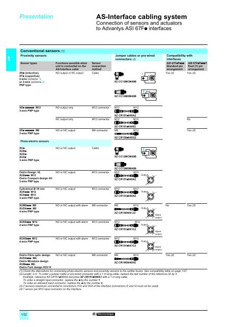
Presentation 1<strong>AS</strong>-<strong>Interface</strong><strong>cabling</strong> <strong>system</strong> 1Connection of sensors and actuatorsto Advantys <strong>AS</strong>I 67Fp interfaces1Conventional sensors (1)Proximity sensorsSensor typesXSp (inductive),XTp (capacitive)2-wire (scheme 1)or 3-wire (scheme 2)PNP typeFunctions possible whenunit is connected on the<strong>AS</strong>-<strong>Interface</strong> cableNO output or NC outputSensorconnectionmethodCableJumper cables or pre-wiredconnectors (2)XZ CC12MCM40B1–+32541Compatibility withinterfaces<strong>AS</strong>I 67FpPpppStandard pinarrangementYes (4) Yes (4)<strong>AS</strong>I 67FpPpppYDual (Y) pinarrangementXZ CC12MDM40B2–+32541XSp pppppp M123-wire PNP typeNO output only M12 connector M12 M12XZ CR151p040A2NC output only M12 connector M12 M12NoXSp pppppp M83-wire PNP typePhoto-electric sensorsXZ CR151p040E2NO or NC output M8 connector M8 M12XZ CR150p040G2Yes (4)XUpXUBpXUKpXUXp3-wire PNP typeNO or NC outputCableXZ CC12MCM40B2–+32541Osiris Design 18,XUBppp M12Osiris Compact design XU3-wire PNP typeCylindricalØ18mmXUKppp M12XUXppp M123-wire PNP typeXUM0ppp M8XUDAppp M84-wire PNP typeXUK0ppp M124-wire PNP typeXUX0ppp M124-wire PNP typeXZ CC12MDM40BNO or NC output M12 connector M12 M12XZ CR151p040A2NO or NC output M12 connector M12 M12XZ CR151p040A2NO or NC output with alarm M8 connector M8 M12XZ CR1509041J2Output4 3 –NO or NC output with alarm M12 connector M12 M12Output4XZ CR151p041C2NO or NC output with alarm M12 connector M12 M12Output4XZ CR151p041C2No Yes (3)Osiris Fibre optic design NO or NC output M8 connector M8 M12Yes (4) Yes (4)XUDAppp M8,Osiris Miniature designXZ CR1509040H2XUMppp M8,Osiris Fork design XUV K(1) Check the alternatives for connecting photo-electric sensors and proximity sensors to the splitter boxes. See compatibility table on page 1/37.(2) Length: 2 m. To order a jumper cable or pre-wired connector with a 1 m long cable, replace the last number of the reference (2) by 1.Example: reference XZ CR151p040A2 becomes XZ CR151p040A1 witha1mlongcable.To order a straight input connector, replace the p by the number 1.To order an elbowed input connector, replace the p by the number 2.(3) 2 sensors maximum connected to connectors I1/I2 and I3/I4 of the interface (connectors I2 and I4 must not be used).(4) 1 sensor per M12 input connector on the interface.+ 1Output4 3 –+ 1Output4+ 1+ 1+ 13 –22Alarmoutput3 –2Alarmoutput3 –Alarmoutput1/32