Fire Alarm Control Panels - Bosch Security Systems
Fire Alarm Control Panels - Bosch Security Systems
Fire Alarm Control Panels - Bosch Security Systems
- No tags were found...

You also want an ePaper? Increase the reach of your titles
YUMPU automatically turns print PDFs into web optimized ePapers that Google loves.
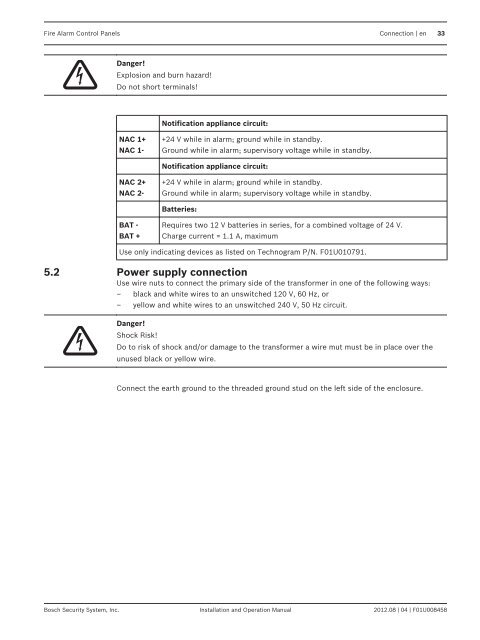
<strong>Fire</strong> <strong>Alarm</strong> <strong>Control</strong> <strong>Panels</strong> Connection | en 33Danger!Explosion and burn hazard!Do not short terminals!Notification appliance circuit:NAC 1+NAC 1-+24 V while in alarm; ground while in standby.Ground while in alarm; supervisory voltage while in standby.Notification appliance circuit:NAC 2+NAC 2-+24 V while in alarm; ground while in standby.Ground while in alarm; supervisory voltage while in standby.Batteries:BAT -BAT +Requires two 12 V batteries in series, for a combined voltage of 24 V.Charge current = 1.1 A, maximumUse only indicating devices as listed on Technogram P/N. F01U010791.5.2Power supply connectionUse wire nuts to connect the primary side of the transformer in one of the following ways:– black and white wires to an unswitched 120 V, 60 Hz, or– yellow and white wires to an unswitched 240 V, 50 Hz circuit.Danger!Shock Risk!Do to risk of shock and/or damage to the transformer a wire mut must be in place over theunused black or yellow wire.Connect the earth ground to the threaded ground stud on the left side of the enclosure.<strong>Bosch</strong> <strong>Security</strong> System, Inc. Installation and Operation Manual 2012.08 | 04 | F01U008458