Create successful ePaper yourself
Turn your PDF publications into a flip-book with our unique Google optimized e-Paper software.
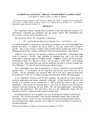
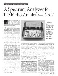
Figure 5—The 10 MHz IF amplifier and log amplifier used in <strong>the</strong> analyzer. Refer to <strong>the</strong> text <strong>for</strong> adjustment details. Unless o<strong>the</strong>rwisespecified, resistors are 1 /4 W, 5% tolerance carbon-composition or film units. Equivalent parts can be substituted.C309—Plastic dielectric trim cap(Sprague-Goodman GYD65000)C307, C308, C310—Silver mica or NP0ceramic capacitors, 10% toleranceC316—0.22 µF ceramicD301—PIN diode; 1N4007 usedL301—1.35 uH, 18 turns #24 enameledwire on T-44-6 core, Q >150Q301, Q302, Q303—2N3904R1—Panel-mount, 1 kΩ linearR2—Panel-mount, 5 kΩ linearU301—Motorola MC3356U302—78L05 +5 V regulatorU303—CA3140 op ampreasoned that builders would want to implement<strong>the</strong>ir own ideas. Maintain reasonableshielding <strong>for</strong> this part of <strong>the</strong> system. Additionalattenuator pads can be inserted in linewith one filter or <strong>the</strong> o<strong>the</strong>r to approximatelyequalize filter loss in <strong>the</strong> two paths.You may want to build crystal filters <strong>for</strong>your analyzer. 9 The VCO stability in thisanalyzer will support resolution bandwidthsas narrow as 3 to 5 kHz. For a simplifiedbeginning, a very practical analyzercan be built with only one resolution bandwidthof 300 kHz.Second Mixer and Second LocalOscillatorFigure 7 shows <strong>the</strong> second mixer andrelated LO. The heart of this module—andto some extent that of <strong>the</strong> entire analyzer—is U202, a high-level second mixer. Thismixer is bombarded by large signals thatare as strong or stronger than those at <strong>the</strong>front end. Accordingly, <strong>the</strong> second mixershould have an intercept similar to that of<strong>the</strong> first mixer. This is <strong>the</strong> usual weak pointin all too many homebrew spectrum analyzers—aswell as more than a few receivers!The second mixer, U202, uses a +17 dBmlevel Mini-Circuits TUF-1H. This is not<strong>the</strong> place <strong>for</strong> a current-starved telephonecomponent! The second mixer is terminatedin a high-pass/low-pass diplexer followedby an IF amplifier (Q202) biased at 50 mA.This is a critical stage <strong>for</strong> dynamic range:Don’t replace it with a monolithic substituteof reduced gain or intercept.The second LO begins with a 100 MHz,fifth-overtone crystal oscillator (Q201),followed by a pad and a power amplifier.The oscillator inductor, L201, in Q201’scollector is made of five turns of #22 wirewound on a 6-32 machine screw. (Remove<strong>the</strong> screw be<strong>for</strong>e installing <strong>the</strong> coil.) Here’san excellent way to align <strong>the</strong> oscillator:Temporarily replace <strong>the</strong> crystal, Y201,with a 51 Ω resistor. Adjust <strong>the</strong> tuned circuituntil oscillation occurs at <strong>the</strong> desired100 MHz frequency. Then, replace <strong>the</strong>51 Ω resistor with <strong>the</strong> 100 MHz crystal; nofur<strong>the</strong>r tuning is required. Measure <strong>the</strong>oscillator’s output with a power meter be<strong>for</strong>eapplying it to U202. Adjust <strong>the</strong> padattenuation (R205, R206, R207) to realize<strong>the</strong> specified LO drive level.After <strong>the</strong> second LO is operating, attachit to <strong>the</strong> second mixer and <strong>the</strong> rest of <strong>the</strong>analyzer. With a second mixer input of–35 dBm at 110 MHz, you should obtain areference-level response.Voltage-Controlled Local Oscillatorand First MixerFigure 8 shows <strong>the</strong> analyzer’s swept LO.The foundation <strong>for</strong> this module is a Mini-Circuits POS-200 VCO module, U101.Similar VCOs are available from manyAugust 1998 39
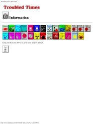
Figure 6—Resolution filters: The upper schematic shows <strong>the</strong> 300 kHz bandwidth 10 MHz LC filter. If desired, that circuit can berealigned at 10.7 MHz without o<strong>the</strong>r design changes. The LC filter is shown as a separate unit connected to <strong>the</strong> rest of <strong>the</strong> analyzerwith coaxial cable. However, <strong>the</strong> filter can be constructed on <strong>the</strong> board with <strong>the</strong> crystal filter and relays. Unless o<strong>the</strong>rwise specified,resistors are 1 /4 W, 5% tolerance carbon-composition or film units. Equivalent parts can be substituted.C501, C502, C504, C505, C507, C508,C510, C511, C513, C514, C515—Silvermica or NP0 ceramic, 5%C503, C506, C509, C512—65 pF plasticdielectric trim cap (Sprague-GoodmanGYD65000)K501, K502—SPDT relay; AromatTF2-12V used here (one contact setunused); values of associated droppingresistors may need adjustment.L501-L504—17 turns of #22 enameledwire on a T-50-6 toroid (1.15 µH),Q > 250vendors. 10 The VCO output is about+10 dBm, too low a level <strong>for</strong> <strong>the</strong> high-levelmixer. A MAV-11 amplifier, U102, precededby a pad to provide level adjustment,increases <strong>the</strong> signal level. Confirm <strong>the</strong> outputpower level be<strong>for</strong>e applying it to <strong>the</strong>mixer, U103.Once <strong>the</strong> VCO output level is adjustedand confirmed, calibrate its frequencyagainst <strong>the</strong> VCO control voltage. If a VHFcounter is not available, you can obtain afew points by tuning <strong>the</strong> VCO to hit localFM broadcast signals of known frequency.Calibrating <strong>the</strong> VCO is useful if <strong>the</strong> moduleis used later as a signal source <strong>for</strong> alignmentof <strong>the</strong> 110 MHz band-pass filter.Figure 8 also shows <strong>the</strong> input mixer,U103, ano<strong>the</strong>r Mini-Circuits TUF-1H, terminatedin a 6 dB pad. Although <strong>the</strong> paddegrades <strong>the</strong> noise figure, it presents a solidoutput termination <strong>for</strong> <strong>the</strong> mixer. Thistermination is reflected, helping to providea good mixer-input impedance match,important in a measurement instrument.The pad is followed by a Mini-CircuitsMAV-11 IF amplifier (U104) that restores<strong>the</strong> gain lost in <strong>the</strong> mixer and pad.The mixer application differs from a40 August 1998normal diode ring: The RF input is nowattached to <strong>the</strong> dc-coupled port. This allowsinput frequencies as low as 50 kHz to beconverted to <strong>the</strong> first IF. The low-frequencyend is limited by mixer LO to RF isolation,which determines <strong>the</strong> LO energy thatreaches <strong>the</strong> first IF. The related on-screenresponse is often termed <strong>the</strong> zero spur, afamiliar “feature” in most RF spectrumanalyzers.This module (VCO and first mixer) iscontained in a shielded enclosure with coaxialinputs and outputs, including coaxialrouting of <strong>the</strong> VCO control voltage. Thefront end is susceptible to any VHF andUHF signals reaching it, making shieldingand decoupling especially important.The 110-MHz IF Band-Pass FilterOne of <strong>the</strong> more-critical blocks in <strong>the</strong>analyzer is <strong>the</strong> filter that establishes <strong>the</strong>bandwidth of <strong>the</strong> VHF IF. The bandwidthmust be at least as wide as <strong>the</strong> widest10 MHz filter, but must be narrow enoughto reject <strong>the</strong> 90 MHz second-conversionimages by 80 dB or more. This per<strong>for</strong>manceis only available with a three-pole orhigher-order filter. The best double-tunedcircuits we built (or computer simulated)came close, but just didn’t cut it.We described double-tuned circuits indetail in a 1991 QST tutorial paper. 11 Thosemethods have recently been extended tothree-resonator filters. 12 One of <strong>the</strong> methodspresented in <strong>the</strong> later paper is a sequentialapproach that begins with a doubletunedcircuit (DTC). First, a DTC is built<strong>for</strong> <strong>the</strong> desired 3 dB bandwidth and has itsper<strong>for</strong>mance confirmed with a widebandsweep (a vital requirement!) Then, a thirdresonator is inserted between <strong>the</strong> originaltwo. Coupling elements similar to <strong>the</strong> onethat produced <strong>the</strong> required DTC bandwidthare repeated in <strong>the</strong> triple-tuned circuit, butend-section loading is not changed. Thecenter frequency of <strong>the</strong> three resonators isaligned to complete <strong>the</strong> filter.The schematic <strong>for</strong> <strong>the</strong> 110 MHz tripletunedcircuit is shown in Figure 9. The inductors,100nH, are made by winding 5turns of #18 wire on <strong>the</strong> shank of a 1 /4-inchdrill bit. These inductors typically have anunloaded Q of just over 200 at 110 MHz.Larger-diameter inductors would have producedhigher unloaded Q with <strong>the</strong> attendantlower insertion loss. However, <strong>the</strong>
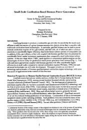
Figure 7⎯Second mixer and second LO.L203 in <strong>the</strong> output of U202 consists of 17turns of #28 enameled wire on a T-30-6toroid. The actual value is not critical anda molded RF choke can be used in placeof <strong>the</strong> toroid. Unless o<strong>the</strong>rwise specified,resistors are 1 /4 W, 5% tolerance carboncompositionor film units. Equivalent partscan be substituted.C201, C202—470 pF ceramicC203, C206—15 pF NP0 ceramic or silvermicaC204, C207—82 pF NP0 ceramic or silvermicaC205—65 pF plastic dielectric trim cap(Sprague-Goodman GYD65000)C211—120 pF, silver mica or NP0 ceramicL201—57 nH; 5 turns of #22 wire woundon a 6-32 machine screw. Remove <strong>the</strong>screw be<strong>for</strong>e installing <strong>the</strong> coil.L202—1 µH molded RFC; any value from100 nH to 2.7 µH is okayL203—0.3 µH; 9 turns #24 enameled wireon a T-30-6 coreQ201—2N5179Q202—2N5109, 2N3866, 2SC1252, etcU201—Mini-Circuits MAV-11U202—Mini-Circuits TUF-1H mixerT201—10 bifilar turns #28 on FT-37-43ferrite toroidstray coupling between coils would haveincreased, which would have necessitatedshields between filter sections. The smaller(10 nH) end-matching inductors are oneinchlengths of #18 wire. The triple-tunedfilter, and its parent DTC, have bandwidthsof 2 to 3 MHz.The filter alignment and experimentationis usually done with a sensitive powermeter, 13 a step attenuator and a signalsource. As mentioned earlier, <strong>the</strong> VCO canserve <strong>the</strong> role of signal generator, if one isnot available.The second-conversion image rejectionis easily measured with a finished analyzer.Apply a 40 MHz signal to <strong>the</strong> analyzer andadjust it <strong>for</strong> a reference-level response.Don’t touch <strong>the</strong> analyzer tuning, but move<strong>the</strong> signal generator to 60 MHz. An imagesignal may appear at <strong>the</strong> same point onscreen as <strong>the</strong> original 40 MHz signal. Therejection was only 66 dB with a DTC used<strong>for</strong> some experiments. The triple-tuned filterproduced 90-dB rejection. The slightextra ef<strong>for</strong>t of <strong>the</strong> triple-tuned circuit iseasily justified. No PC board is available<strong>for</strong> <strong>the</strong> IF filter.Input Low-Pass FilterA 70 MHz low-pass filter is shown inFigure 10. This circuit and a step attenuatorare housed in separate shielded enclosuresin one of our analyzers. In <strong>the</strong> o<strong>the</strong>r, <strong>the</strong> filterand <strong>the</strong> attenuator remain outboard elements.Integral components are more convenient<strong>for</strong> routine analyzer applications,but incorporation removes <strong>the</strong>m from <strong>the</strong>equipment pool available <strong>for</strong> o<strong>the</strong>r experiments.Also, operation without an outboardlow-pass filter allows <strong>the</strong> instrument to beAugust 1998 41
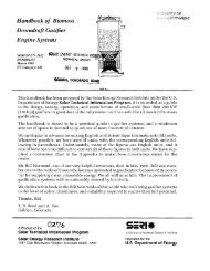
Figure 8—Front-end <strong>for</strong> <strong>the</strong> spectrum analyzer. The LO drive level is set to between +16 and +18 dBm by trimming <strong>the</strong> padattenuation. The 1 µH inductors used in <strong>the</strong> MAV-11 outputs can be molded RF chokes or made of 17 turns of #28 enameled wirewound on T-30-6 toroids. Unless o<strong>the</strong>rwise specified, resistors are 1 /4 W, 5% tolerance carbon-composition or film units. Equivalentparts can be substituted.L101, L102—1 µH molded RFC; anyvalue between 100 nH to 2.7 µH suitableU101—Mini-Circuits POS-200 VCOU102, U104—Mini-Circuits MAV-11U103—Mini-Circuits TUF-1HFigure 9—VHF band-pass filter used in <strong>the</strong> 110 MHz IF.42 August 1998
11Wes Hayward, W7ZOI, “The Double TunedCircuit: An Experimenter’s Tutorial,” QST,Dec 91, pp 29-34.12Wes Hayward, W7ZOI, “Extending <strong>the</strong>Double-Tuned Circuit to Three Resonators,”QEX, March-April, 1998, pp 41-46.13Denton Bramwell, K7OWJ, “The Microwatter,”QST, Jun 1997, pp 33-35. Also, see <strong>the</strong>sidebar in <strong>the</strong> referent of Note 11.Figure 10—Input 70 MHz low-pass filter. The filter started as a ninth-orderChebyshev design, but was modified through computer manipulation to use equalvalueinductors and standard-value capacitors. The inductors each consist of 8 turnsof #22 wire. The wire is wound on <strong>the</strong> threads a 1 /4-20 bolt as a <strong>for</strong>m; remove <strong>the</strong> boltafter winding <strong>the</strong> inductor. See text.C701-C705—NP0 ceramic, 5% tolerance. L701-L704—8 turns #22 bare wire woundin 1/4-20 bolt threads; see text.used well into <strong>the</strong> low UHF area by operating<strong>the</strong> mixer with VCO harmonics. (Nocircuit boards are available <strong>for</strong> this filter.)Construction and Adjustment HintsThe spectrum analyzer can be built usinga number of RF techniques. Our analyzersare collections of small boxes usingcoaxial-cable interconnections. Power suppliesreach <strong>the</strong> interior of RF modulesthrough feedthrough capacitors. The onlyopen boards in <strong>the</strong> system are <strong>the</strong> time baseand (in one instrument) <strong>the</strong> log amp, bothconstrained to low frequencies. The110 MHz IF filter and all RF circuit boardsare designed to fit in Hammond 1590Bdiecast aluminum alloy boxes.The sensitivity of such RF measurementequipment justifies <strong>the</strong> extensive shielding.Spurious responses are readily seen on <strong>the</strong>display. While a few can be tolerated, <strong>the</strong>yseriously detract from a measurementwhen, <strong>for</strong> example, spurious transmitterproducts are being examined.Most of <strong>the</strong> adjustment has already beendiscussed. Indeed, by <strong>the</strong> time <strong>the</strong> analyzeris finished, <strong>the</strong>re is little alignment left! Theblock diagram (Figure 1) has typical signallevels shown in paren<strong>the</strong>ses.The finished analyzer is set up with a–30 dBm signal from a stable-impedancesource. Adjust <strong>the</strong> IF gain to establish <strong>the</strong>reference level. If <strong>the</strong> 10 dB per divisiontracking is not quite correct, change <strong>the</strong> logamp gain, followed by a readjustment of<strong>the</strong> IF gain until tracking is correct. IF gainis adjusted to <strong>the</strong> reference level whenever<strong>the</strong> analyzer is used.Next month, we’ll present methods toextend <strong>the</strong> analyzer to higher frequencies.We’ll discuss simple test equipment thatcan be used in alignment and present sometypical examples of spectrum-analyzer use.Notes1Homebrew analyzers described in amateur literaturein recent years have often used TVtuners as <strong>the</strong> front end. See, <strong>for</strong> example, AlHelfrick, K2BLA, “An Inexpensive <strong>Spectrum</strong><strong>Analyzer</strong> <strong>for</strong> <strong>the</strong> <strong>Radio</strong> <strong>Amateur</strong>,” QST, Nov1985, pp 23-29. A more recent example isFred Brown, W6HPH, “Build a 5- to 850-MHz<strong>Spectrum</strong> <strong>Analyzer</strong>,” Communications Quarterly,Winter, 1997, pp 91-96.2The usual unit <strong>for</strong> power measurement with aspectrum analyzer is dBm. This is an absolute,impedance invariant unit, signifyingpower compared with 1 mW. Hence, –30 dBmis 30 dB below a milliwatt, or a microwatt. ThedBm unit is especially useful in spectrumanalysis where two levels are often compared.The difference between two powersin dBm is a power ratio in dB. (See JayCraswell, WBØVNE, “Converting BetweendBm, Milliwatts and Watts,” Technical Correspondence,QST, Jul 1998, p 70.—Ed.)3Excellent homebrew VCOs can be builtusing <strong>the</strong> work of Allan Victor, WA4MGX,“Wideband VCO Design,” Ham <strong>Radio</strong> Magazine,Jul, 1984, pp 49-58. See also <strong>the</strong> recentwork of Colin Horrabin, G3SBI, as reprintedin “Tech Notes,” Communications Quarterly,Winter, 1996, pp 94-104.4Many amateurs are uncom<strong>for</strong>table with opampcircuits, a situation easily remedied by astudy of <strong>the</strong> excellent text by Horowitz andHill, “The Art of Electronics,” 2nd Edition,Cambridge University Press, 1989. See <strong>the</strong>golden rules presented on page 177. An opampintegrator is presented on page 222. Thein<strong>for</strong>mation on sawtooth oscillators beginningon page 288 is also useful.5PC boards <strong>for</strong> several of <strong>the</strong> analyzer circuitsare available from Kanga USA. Details areavailable at <strong>the</strong> Kanga Web site, http://www.bright.net/~kanga/kanga/, or fromKanga USA, 3521 Spring Lake Dr, Findlay,OH 45840.6The best digital audio recording and playbacksystems have a dynamic range around 90 dB.7An outstanding fundamental treatment of logamps is given in applications data from AnalogDevices. See, <strong>for</strong> example, <strong>the</strong> data sheet<strong>for</strong> <strong>the</strong> AD8307, Analog Devices, Norwood,MA, 1997, http://www.analog.com/product/Product_Center.html.8The log/IF board available from Kanga (seeNote 5) is configured <strong>for</strong> <strong>the</strong> MC3356. Mostof <strong>the</strong> 20 pins allotted to <strong>the</strong> IC are not usedand <strong>the</strong>ir locations can be employed to breadboardand retrofit <strong>the</strong> AD8307 (8 pin DIP) into<strong>the</strong> system, if desired.9If crystal filters are built especially <strong>for</strong> thisproject, we recommend a peaked responseshape (such as Gaussian-to-6 dB). We haveinvestigated wider bandwidth crystal filters aspresented in Wes Hayward, W7ZOI, “Refinementsin Crystal Ladder Filter Design,” QEX,Jun, 1995, pp 16-21. See also <strong>the</strong> carefulwork of Bill Carver, “High Per<strong>for</strong>mance CrystalFilter Design,” Communications Quarterly,Winter, 1993, pp 11-18, and that of JacobMakhinson, N6NWP, “Designing and BuildingHigh Per<strong>for</strong>mance Crystal Ladder Filters,”QEX, Jan 1995, pp 3-17.10See <strong>the</strong> Mini-Circuits catalogs and applicationsmanuals. A family of viable VCOs arealso available from Synergy Microwave.These units are more expensive, but offerlower phase noise, which would be significant<strong>for</strong> more-stringent applications.Wes Hayward, W7ZOI, and Terry White,K7TAU, are not strangers to QST. This is alsonot <strong>the</strong> first QST project on which <strong>the</strong>y’veworked toge<strong>the</strong>r. The first, “The Mountaineer—AnUltraportable CW Station,” describeda QRP transceiver and appeared in <strong>the</strong> August1972 issue. At <strong>the</strong> time this spectrum-analyzerproject evolved, <strong>the</strong> authors worked toge<strong>the</strong>r in<strong>the</strong> Advanced Circuits section of <strong>the</strong> ReceiverGroup at TriQuint Semiconductor in Hillsboro,Oregon. Over <strong>the</strong> years, Wes has providedreaders of QST, The Handbook and o<strong>the</strong>rARRL publications with a wealth of projectsand technological know-how. You can contactWes at 7700 SW Danielle Ave, Beaverton, OR97008; e-mail w7zoi@teleport.com. Terrycan be reached at 9480 S Gribble Rd, Canby,OR 97013; e-mail twhite@tqs.com.New ProductsATV TRANSMITTER FROMPC ELECTRONICS◊ The TX70-10 ATV transmitter from PCelectronics is aimed at operators who usecable-ready TVs (tuned to channels 57-60)to receive amateur television signals in <strong>the</strong>70-cm ham band. The continuous-duty transmitterputs out 10 W AM (color or blackand-white,just like broadcast TV stations)and features a built-in T/R relay, variablepower output, front-panel RCA jacks <strong>for</strong>video and audio (with line and mic inputs), avideo monitor circuit and a PTL jack (pushto-look)in parallel with <strong>the</strong> unit’s T/Rswitch.The TX70-10 is housed in a die cast aluminumbox measuring about 7×5×3 inchesand is powered by 13.8 V dc at 3 A. The unitcomes with one user-specified crystal in <strong>the</strong>440-MHz range. An optional second frontpanel-selectedcrystal is available <strong>for</strong> $20.A repeater version, <strong>the</strong> RTX70-10, is alsoavailable.Price: $439 shipped to <strong>the</strong> lower 48 states.For more in<strong>for</strong>mation, contact PC Electronics,2522 Paxson Ln, Arcadia, CA 91007; tel626-447-4565; tomsmb@aol.com.August 1998 43