


You also want an ePaper? Increase the reach of your titles
YUMPU automatically turns print PDFs into web optimized ePapers that Google loves.
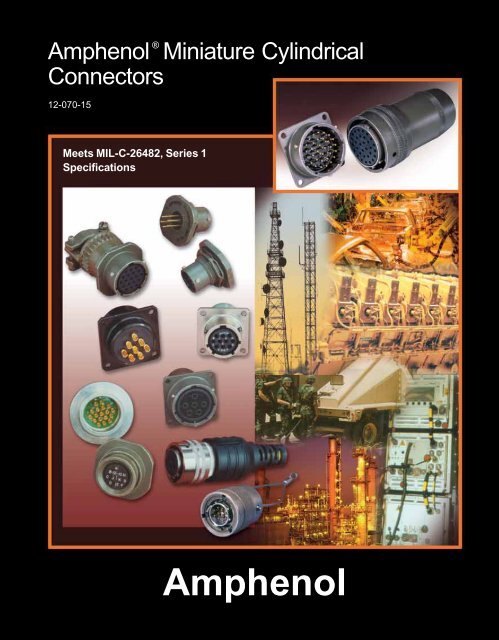
®<strong>Amphenol</strong> Miniature Cylindrical ConnectorsProprietary/MIL-C-26482, Series 1<strong>Amphenol</strong> ® Miniature Cylindrical connectors offer twice the number of contacts in just half the size of a Standard connector. Theseminiature connectors, are available in several series, each with varying design characteristics and customer options to meet cost considerationsand provide maximum design flexibility. There are two styles within the family that are MS approved and qualified to MIL-C-26482, Series 1, and in addition there are several proprietary styles.Common features of all styles:• All are for general duty applications and environmental sealing is achieved with the grommet and clamp design.• Operating temperature is from –55°C to +125°; Operating voltage to 1000 VAC (RMS) at sea level.• Pin and socket contacts are machined from low loss copper alloy and gold plated to eliminate contact corrosion and provide anindefinite shelf life.• All have resilient inserts which provide high dielectric strength and moisture barrier.• A variety of shell finishes (including non-cadmium) and a variety of backend accessories are available within the styles.PT Solderjam nut receptacle andmated straight plugPT Solderwall mount receptaclePT-SE Crimpwall mount receptacleand mated straight plugPC Threaded Crimpstraight plug and wallmount receptacleBayonet Coupling with Solder Contact TerminationPT, MS/PT (solder)• MS and proprietary versions• Factory installed solder contacts• 3 point bayonet coupling and 5 key/keyway mating.• Intermateable with all miniature series connectors except threadedPC series.• MS/PT meets MIL-C-26482 Series 1, service classes E, F and P.• MS/PT is UL recognized.SP (solder)• SP Series is a modification of the PT with same features except awider flange for back panel mountingBayonet Coupling with Crimp Contact TerminationPT-SE, MS/PT-SE (crimp)• MS and proprietary versions• Crimp rear insertable/front release contact termination. (closed entrysocket insert prevents probe damage).• 3 point bayonet coupling and 5 key/keyway mating.• Intermateable with all miniature series connectors except threadedPC series.• MS/PT-SE meets MIL-C-26482 Series 1, service classes E, F, P.SP-SE (crimp)• Modification of the PT-SE with wider flange for back panel mountingPT-CE, SP-CE (crimp)• Incorporates a special one-piece insert and grommet assemblyThreaded Coupling with Solder Contact TerminationPC (solder) Proprietary• Double stub threaded coupling and single hole polarization.• Factory installed solder contactsThreaded Coupling with Crimp Contact TerminationTwo threaded PC styles are offered in some shell sizes. Both havecrimp front release and front removable contacts, but they have differentretention systems.PC-SE (crimp) Proprietary - with spring tower retention system• Spring tower retention systemPC-CE (crimp) Proprietary - with nylon wafer dielectric system1Options• 7 shell styles with 60 insert patterns• Hermetic seal (glass fusion) receptaclestyles available• Pressurized thru bulkhead receptaclestyle available• Breakaway quick disconnect styles• EMI filter protection styles• Pre-installed coax solder contactsare available• Printed circuit board contacts areavailableOptions• 6 shell styles with 47 insert patterns• Breakaway quick disconnect styleavailable• Coax and thermocouple contacts areavailableOptions• 5 shell styles with 60 insert patterns• Hermetic receptacles available• Pressurized thru bulkhead receptaclestyle available• Pre-installed coax solder contactsare available.Options• 5 shell styles (consult <strong>Amphenol</strong> foravailability of shell sizes and insertpatterns)
®<strong>Amphenol</strong> Miniature Cylindricaldesign flexibilityThe large family of miniature proprietary and MS style connectors provides formany optional features and designs. In addition to the choices of bayonet orthreaded shells, solder or crimp termination within the style variations, there areadditional options that are shown here.HermeticsHermetically sealed receptacles have fused compression glass sealedinserts which provide envionrmental moisture sealing. There are threehermetic styles within the PT bayonet series and three hermetic styleswithin the PC threaded series.Coaxial Contacts<strong>Amphenol</strong> Miniature connectors can incorporate shielded coaxcontacts. Size 8 and 12 crimp coax contacts are available in PT-SE,SP-SE, MS/PT-SE. Factory installed size 8 and 12 solder type coaxcontacts are available in PT, SP,MS/PT connectors. See coax contactinformation pages at the end of this catalog.Printed Circuit Board Tail ContactsPT bayonet connectors in box mounting receptacle and jam nut receptacle styles are availablewith printed circuit board contacts. Standard PCB tails for MIL-C-26482 connectorshave gold plating, .0050 inches over nickel. See page 20 and call <strong>Amphenol</strong> for further information.Flex CircuitryFlex termination assemblies for attaching cylindrical connectors to printed circuit boards areavailable through the <strong>Amphenol</strong> division ACT, Advanced Circuit Technology. Flex can beused with miniature 26482 connectors and it can be designed to meet specific length, currentcarrying capacity and to fit the precise geometric shape of the connector to board package.Flex circuity plugs into a printed circuit board and creates a self-locking terminal pad whicheliminates the need for an additional interconnect to the PCB.Breakaway, Twist Pull MiniaturesQuick disconnect “breakaway” styles are shown in this catalogs. These are available in PTsolder style plugs (page 26), PT-SE crimp style plugs (page 38) or PT-CE crimp style plugs(page 48). Quick disconnect of the connector plug from the receptacle is accomplished withaxial pull on the lanyard. This instant decoupling and damage free separation is ideal forweapons release and blind or difficult accessibility situations. Separation forces vary perconnector series. The plug and receptacle need to be fully mated before disengagement bythe lanyard pull.Filter Protection<strong>Amphenol</strong> offers the FPT Series which combines the miniature PTseries with an EMI filter. Designed to provide EMI protection forsensitive circuits, each circuit is individually filtered within the connector,eliminating the need for costly and bulky exterior networkfilters. Filter contacts are available in MF, HF, VHF, and UHFranges and are intermateable and intermountable with MIL-C-26482 connectors. For further information see catalog 12-120,<strong>Amphenol</strong> EMI Filter Transient Protection Connectors. (online atwww.amphenol-aerospace.com).26482 Connector with HermeticSeal Insert and Coax Contacts26482 Connector with EMIFilter ProtectionOvermolded CableOvermold seals and cables can be designed for almost any industrial application. A varietyof materials are available: neoprene, hypalon and others; and a variety of lengths can bedesigned to meet customer specifications. Overmold seals to the rear of the connector andto the cable jacket providing moisture sealing.226482 Connector with PC TailContacts26482 Connector with FlexBreakaway Twist Pull 2648226482 Connector with OvermoldedCable
®<strong>Amphenol</strong> Miniature Cylindricalconnector selection guideThe accompanying chart is provided to assist the user in selectingthe appropriate type of miniature connector to meet the applicationrequirements. Further information can be found in specific sectionsof this catalog.CHARACTERISTICSSolderPT MS/PT SP PCCrimpMS/PT-SE PT-SE SP-SE PC-SE PT-CE SP-CE PC-CEIntermateable† o o o X o o o X o o XContacts Solder • • • •Crimp RI/FR • • • • • • •Contact RetentionSystemNon-Removable • • • •Removable • • • • • • •Coupling Bayonet • • • • • • • •Threaded • • •Standard Finishes†† Olive Drab Cadmium (003) • • • • •Anodic Coated (005) • • •Bright Cadmium (001) • • •Temperature Range Resilient Dielectric (–55°C to +125°C) • • • • • • • • • • •Wide Mounting Flange • • •Hermetic Seal • • • •SHELL STYLE AVAILABILITYWall Mounting Receptacle “00” • • • • • **• • • • •Cable Connecting Receptacle “01” *** • • • • • • • •Box Mounting Receptacle “02” *• • • *• • **• • • • •Straight Plug “06” • • • • • • • • • • •Jam Nut Receptacle “07” *• *• • *• • • • • • • •Thru-bulkhead Receptacle “TB” • •Solder Mount Receptacle “I” *• *• *•90° Plug “08” • • • • • • • •RI/FR = Rear Insertion/Front Releasable† o intermates with oX intermates with X†† Optional finishes available. See “how to order” sections.* Available in hermetic version** Dual mounting holes*** This connector style is sometimes referred to as a cable connecting “plug.”It does, however, mate with either a straight or 90 degree plug.<strong>Amphenol</strong> ® /Matrix ® MIL-C-26482, Series 2 bayonet coupling connectors with rear insertable and rear releaseablecontacts are covered in another catalog - See pageXX for a brief description and see complete details in catalog 12-071which is online at www.amphenol-aerospace.com.3
®<strong>Amphenol</strong> Miniature Cylindricalinsert availability, cont.INSERT AVAILABILITYInsertArrangementSolder TerminationMS/PT PT SP PCHermeticPTMS-PTPCCrimp TerminationMS/PT-SEPT-SESP-SEPC-SEPT-CESP-CEPC-CETotalContacts 20 16 12Contact SizeCoax12 8ServiceRating18-32 X X X X X X X 32 32 I18-71 X* 9 8 1 Coax, II18-72 X X X 14 10 4 N/A18-75 X X X 4 4 Coax18-76 4 3 1 II18-80 X X X X 8 6 2 Coax, I18-91 HV X* X 6 6 **20-16 X X X X X X X 16 16 II20-24 X X X X X 24 24 I20-25 X X X 25 25 I20-26 X X X 26 20 6 I20-27 X X X X X 27 27 I20-39 X X X X X X X 39 37 2 I20-41 X X X X X X X 41 41 I20-70 14 10 4 Coax20-90 HV X X X 7 7 Hi-Voltage22-7 X X X X* 7 7 Coax22-21 X X X X X X X 21 21 II22-25 X* 25 25 I22-32 X X X X X P 32 32 I22-34 X X X X 34 34 I22-36 X X X X 36 36 I22-41 X X X X X X X 41 27 14 I22-55 X X X X X X X 55 55 I22-70 X X X 19 13 6 I, Coax22-71 9 2 7 I, Coax22-72 X X X 19 12 4 3 N/A22-78††† X* 7 7 Coax22-96 X* 7 7† II24-31 X X X X 31 31 I24-51 X* 51 47 4 I24-61 X X X X X X X 61 61 I24-71 X X X 49 45 2 2 N/A24-79 6 1 5 Coax*Not available in MS version**Flashover voltage 5,000 VAC (RMS)***1500 VAC (RMS)†Size 12 contacts for #10 wire††Not presently tooled†††Contacts must be ordered separately5
®<strong>Amphenol</strong> Miniature Breakaway Twist Pullinsert availabilityInsert Availability - Breakway Twist PullCrimpTerminationSolderTerminationContact SizeInsertTotalServiceArrangement PT-CE PT-SE PT Contacts 20 16 12 Rating8-2 X X 2 2 I8-3 X X 3 3 I8-4 X X 4 4 I10-2 X 2 2 I10-6 X X X 6 6 I10-98 X X 6 6 I10-99 X X 7 7 I12-3 X X X 3 3 II12-4 X 4 4 I12-8 X X X 8 8 I12-10 X X X 10 10 I12-98 X 10 10 I14-2 X 2 2 II14-5 X X X 5 5 II14-8 X 8 6 2 I14-12 X X X 12 8 4 I14-15 X X X 15 14 1 I14-16 X 4 2 2 II14-18 X X X 18 18 I14-19 X X X 19 19 I14-91 X X 3 3* H.V.16-6 X 6 6 I16-8 X X X 8 8 II16-23 X X X 23 22 1 I16-26 X X X 26 26 I16-99 X X 23 21 2 I18-5 X X 5 5 II18-11 X X X 11 11 II18-28 X X 28 26 2 I18-30 X X X 30 29 1 I18-32 X X X 32 32 I18-91 X X 6 6* H.V.20-8 X 8 8 I20-16 X X X 16 16 II20-24 X X 24 24 I20-25 X 25 25 I20-27 X X 27 27 I20-39 X X X 39 37 2 I20-41 X X X 41 41 I22-8 X 8 8 II22-21 X X X 21 21 II22-25 X 25 25 I22-32 X X X 32 32 I22-34 X X 34 34 I22-36 X X 36 36 I22-41 X X 41 27 14 I22-55 X X X 55 55 I22-96 X 7 7† II22-97 X 16 16 II22-99 X 11 11 II24-31 X 31 31 I24-61 X X X 61 61 IFor further information regarding any additionalinsert patterns available in Breakaway Miniatureconnectors, please contact <strong>Amphenol</strong> <strong>Aerospace</strong>.For availability of shielded coax contacts withinBreakaway Miniature connectors contact <strong>Amphenol</strong>.TheBreakaway style pages are: PT (solder)breakaway plug is on page 26, the PT-SE (crimp)breakaway plug is on page 38, and the PT-CE(crimp) breakaway plug is on page 48.* 5KV Voltage Rating† Size 12 contact for #10 wire.6
®<strong>Amphenol</strong> Miniature Cylindricalalternate positioningAlternate PositioningTo avoid cross-plugging problems in applications requiringthe use of more than one miniature cylindrical connector ofthe same size and arrangement, alternate insert rotationsare available as indicated in the accompanying chart.As shown in the diagram at right, the front face of the pininsert is rotated within the shell in a clockwise direction fromthe normal shell key. The socket insert would be rotatedcounterclockwise the same number of degrees in respect tothe normal shell key.A BA BPosition W Position X Position Y Position ZViews looking into front face of pin insert or rear of socket insert.A BA BInsert RotationShell InsertDegreesSize Arrangement W X Y Z6 6-1 – – – –8 8-2* 58 122 – –8 8-3 60 210 – –8 8-4* 45 97 184 –8 8-33* 90 – – –8 8-98 – – – –10 10-2 45 90 315 –10 10-5* 45 151 180 27010 10-6* 90 – – –10 10-70 – – – –10 10-98* 90 180 240 27012 12-3* – – 180 –12 12-4* 38 – – –12 12-8 90 112 203 29212 12-10* 60 155 270 29512 12-14 – – – –12 12-98* 61 135 189 34014 14-2 58 122 – –14 14-4* 45 – – –14 14-5* 40 92 184 27314 14-8 48 162 189 31214 14-12* 43 90 – –14 14-15* 17 110 155 23414 14-18* 15 90 180 27014 14-19* 30 165 315 –14 14-22 45 – – –14 14-71 – – – –14 14-91HV – 60 – –14 14-AA* 45 – – –16 16-8* 54 152 180 33116 16-23 158 270 – –16 16-26* 60 – 275 33816 16-70 41 122 216 28616 16-76 – – – –16 16-99* 66 156 223 34018 18-5 55 97 263 31518 18-8 180 – – –Insert RotationShell InsertDegreesSize Arrangement W X Y Z18 18-11* 62 119 241 34018 18-30* 180 193 285 35018 18-32* 85 138 222 26518 18-71 18 108 127 21518 18-72 53 102 213 29318 18-75 45 – – –18 18-76 – – – –18 18-80 45 90 135 16018 18-91HV 90 180 240 27020 20-16* 238 318 333 34720 20-24 70 145 215 29020 20-25 72 144 216 28820 20-26 13 107 210 32220 20-27 72 144 216 28820 20-39* 63 144 252 33320 20-41* 45 126 225 –20 20-70 63 135 222 33520 20-90 45 135 225 31522 22-7 19 41 – –22 22-21* 16 135 175 34922 22-25 60 125 211 33622 22-32 72 145 215 28822 22-34 62 142 218 29822 22-36 72 144 216 28822 22-41 39 135 264 –22 22-55* 30 142 226 31422 22-70 30 82 218 31222 22-71 33 191 236 27022 22-72 42 200 277 33922 22-78 19 41 – –22 22-96* 19 41 – –24 24-31 90 225 255 –24 24-51 22 171 313 –24 24-61* 90 180 270 32424 24-71 39 131 205 28124 24-79 – – – –* Available in Hermetic Class7
®<strong>Amphenol</strong> Miniature Cylindricalinsert arrangementsfront face of pin inserts illustratedBAC ABADBCCBACBABAInsert Arrangement 6-1 8-2 8-3 8-4 8-33 8-98 10-2Service Rating I I I I I I INumber of Contacts 1 2 3 4 3 3 2Contact Size 20 20 20 20 20 20 16EDCABFEDACBEDAF BCCBADCABGFEABHCDInsert Arrangement 10-5 10-6 10-70 10-98 12-3 12-4 12-8Service Rating I I Coax I II I INumber of Contacts 5 6 1 6 3 4 8Contact Size 20 20 8 Coax 20 16 16 20GH A BK JF E DCBAEDJKNCF HLMRPHGABCK JF DEDCABEDACBGHFAEBCDInsert Arrangement 12-10 12-14 12-98 14-2 14-4 14-5 14-8Service Rating I I I II I II INumber of Contacts 10 14 10 2 4 5 6 2Contact Size 20 20 20 12 12 16 20 12GMFHEAJ BKL CDKJRHGL AMPFBNCDEL AK M N BJ T U P CHS RDG F EM ABL N PCK U VRDJ T SEHG FBCEADDACBCABInsert Arrangement 14-12 14-15 14-18 14-19 14-22 14-71 14-91HVFlashoverService Rating I I I I I I5,000 VAC (RMS)Number of Contacts 8 4 14 1 18 19 1 4 3 1 3Contact Size 20 16 20 16 20 20 20 12 16 8 Coax 208For contact legend see page 61.
®<strong>Amphenol</strong> Miniature Cylindricalinsert arrangementsfront face of pin inserts illustratedDCABFGEAHDBCNMYLXKWJHP AR BSZ CTDUEVFGPNaRSMZLYKJABTCUbDc VEXW FGHPGNFMEAHBJCRKL DInsert Arrangement 14-AA 16-8 16-23 16-26 16-70Service Rating I II I I N/ANumber of Contacts 4 8 22 1 26 14 1Contact Size 12 16 20 16 20 20 12 CoaxKJHGNALPMFBCDER APBN S T CY Z UDMXVLW EKFJ H GEDACBFGEAHDBCGHFJAKLDEBCInsert Arrangement 16-76 16-99 18-5 18-8 18-11Service RatingFlashover1.500 VAC (RMS)I II I IINumber of Contacts 8 1 5 21 2 5 8 11Contact Size 20 12* 2 Coax* 20 16 12 12 16*Contact Positions OptionalSR dP cN bMagLZKJABT CeU DVEfWFYXGHST AR U BeVPCdfWNjgDcXMEhbYFLa ZHKJ GGFHAJEBDCKJPHGFL ABMCNDEInsert Arrangement 18-30 18-32 18-71 18-72Service Rating I I II, Coax N/ANumber of Contacts 29 1 32 8 1 10 4Contact Size 20 16 20 16 8 Coax 20 12 CoaxAAADBHBDCABCGCEFBFDEDCInsert Arrangement 18-75 18-76 18-80 18-91 HVFlashoverService Rating Coax II I, Coax5,000 VAC (RMS)Number of Contacts 4 3 1 6 2 6Contact Size 8 Coax 12 Coax 8 Coax 20 8 Coax 209
®<strong>Amphenol</strong> Miniature Cylindricalinsert arrangementsfront face of pin inserts illustratedJKHLSRGMFANPEBDCKJHL MWXaVZUTGFANBYPCRDSEARBNP X S CDYM WTEbZL V a U FGKJ HPNRMSLUTacZKVYAB CDWb EFXGHJInsert Arrangement 20-16 20-24 20-25 20-26Service Rating II I I INumber of Contacts 16 24 25 20 6Contact Size 16 20 20 20 12RPaNZMdYLXKJAbWHBS CT Dc EUFVGVW AUXBjYTCikZSDh rmaERgbq p n FPfcNGe dMHL K JA BWCXV jY DU i kZ Es mT hta FSrngGbR q pfHcP e d JNKM LPHJGKFLNAEBMCDInsert Arrangement 20-27 20-39 20-41 20-70Service Rating I I I CoaxNumber of Contacts 27 37 2 41 10 4Contact Size 20 20 16 20 20 8 CoaxAG BFE DCFEAGDBCNMWLVKJUHPXGABRCSDTEFLMKPNYXbWJHARBSZTaUVFGCEDInsert Arrangement 20-90 22-7 22-21 22-25Service Rating Hi-Voltage Coax II INumber of Contacts 7 7 21 25Contact Size 20 8 Coax 16 16N APbRMBa h c SLCZ g j d TKDf eYUJEXVWHFGTSRdPNcbkjMaLKAUelhZJBVfgYHCWXGDFENPMRedcLSfmlbKT AU BVCgh WnDj XEkYFZaGJ HXWjVAYZBCkamDbsnEU itcrpFT h q d GgSeHfRJPN M L KInsert Arrangement 22-32 22-34 22-36 22-41Service Rating I I I INumber of Contacts 32 34 36 27 14Contact Size 20 20 20 20 1610
®<strong>Amphenol</strong> Miniature Cylindricalinsert arrangementsfront face of pin inserts illustratedU AATBASVCHJAnWMBmpk AAXFBKBq YRBBDzGG CCrLU N CGJ SL CZVP jHH s EVy FF DD aK TP DUTRMN iEE t Fxu bJS REH PN Dh w v cFM gd GGELf eHFECHKJGDInsert Arrangement 22-55 22-70 22-71 22-72Service Rating I I, Coax I, Coax N/ANumber of Contacts 55 13 6 2 7 12 4 3Contact Size 20 20 8 Coax 20 8 Coax 20 16 8 CoaxAM Aa AZBAL N BYCbZPuc DFBXFBY a QtAA dEGKfb CW s yv eGX g RFVDD BBrfJ ec DzECGW d SU qCCgxwVTh HT pECH U Ei JG FSnjm k KDRDPLN MInsert Arrangement 22-78 22-96 24-31 24-51Service Rating Coax II I INumber of Contacts 7 7 31 47 4Contact Size 8 Coax 12 for 16 20 12 Coax# 10 wireAZa b BYc Cu vXdtDHH weW GGxs NN JJEfV FF PP y Fr MM KKgU EE LL zqGhDDAATpHCC BB iS nj Jm kR KPN L MZa AYBX s t b c CW yzDurdBB AAV qEepfFUng GT m x w v hHS kRPjiJN M L KDCEFABInsert Arrangement 24-61 24-71 24-79Service Rating I N/A CoaxNumber of Contacts 61 45 2 2 1 5Contact Size 20 20 16 8 Coax 20 8 Coax11Contact LegendSymbolContact Size201612HV12 Coax8 Coax
®<strong>Amphenol</strong> PT, SP, MS/PTProprietary/MIL-C-26482, Series 1bayonet coupling and solder termination<strong>Amphenol</strong> ® solder contact miniature cylindrical connectorsmeet the most critical application needs. Design versatilitycombined with high reliability performance makes theseseries of Miniature Cylindrical Connectors ideal for environmentalsealing or pressurized applications.wall mountingreceptaclecable connectingreceptacle*box mountingreceptaclestraight plugjam nutreceptacleThe MS/PT Series is qualified to MIL-C-26482, Series 1 and hasall the outstanding design characteristics and quality of the PTSeries. The SP Series is a modification of the PT, providing specialshells with a wide mounting flange for back panel mounting.A corrosion resistant electrically conductive finish of cadmiumplate with an olive drab chromate after-treatment is used on the PTand MS/PT. The SP is given a durable non-conductive hard anodic“Alumilite” ® coating which provides abrasion protection and resistanceto corrosion.Shell components for these series are aluminum. The dependable5 key/keyway polarization with bayonet lock coupling assures positivemating with no chance of cross plugging. Spring tension providedby a wave washer in the coupling nut ensures maintenanceof interfacial seal between mating halves.Both the insert and main joint gasket are molded from resilientneoprene. This provides excellent moisture sealing at the gasketand superior electrical isolation of the contact in the insert.Both pins and sockets are machined from a copper alloy and aregold plated. This gold plating eliminates contact corrosion andoffers an indefinite shelf life. Socket contacts for these series are aclosed entry design. A breakaway style plug is available in the PTsolder series. Hermetics receptacles are available in PT and MS/PT solder series. Receptacles with printed circuit board contactsare also available.PT Solder is UL recognized under file #E115497, Vol. 1, Sec. 5.The PT, SP and MS/PT Series are intermateable and intermountablewith all existing Miniature Cylindrical Series connectorsexcept for the threaded coupling PC Series.Refer to pages 4-11 for insert arrangement availability.PT, SP, MS/PTCONTACT DATA/CONNECTOR RATINGSthru bulkheadreceptaclebreakawaytwist pullplug12ContactSizeServiceRatingTestCurrentContact SpecificationsMaximumMillivolt Drop†Solder WellDiameter+.004–.000+.005–.003+.004–.00220 7.5 55 .046 .12516 13.0 50 .078 .18812 23.0 42 .116 .188RecommendedOperatingAC Voltageat Sea LevelService RatingSeaLevelTest Voltage AC (RMS), 60 cps50,000ft.70,000ft.Solder WellDepth+.031–.000+.031–.000+.031–.000110,000ft.I 600 1,500 500 375 200II 1,000 2,300 750 500 200† Silver plated wire per MIL-C-26482* This connector style is sometimes referred to as a cable connecting“plug.” It does, however, mate with a straight or 90 degree plug.
PT, SP Service ClassesPT and SP connectors are available in the serviceclasses listed below. Each class, with the exception ofhermetic, offers one or more means of terminating orsupporting a cable or wire bundle. Class “W” is notavailable in the SP Series.“A” General duty; back shell is threaded for conduitattachment of MS3057 cable clamp“A” (SR) General duty, with strain relief clamp forcable or wire bundle support“C” Pressurized receptacle; less than 1 cu. in.per hour leakage at 30 psi over a temperaturerange of –65°F to +257°F“E” Environmental resistant connectors - suppliedwith a multi-holed grommet and clampingnut for moisture-proofing individual openwires“E” (SR) Environmental resistant strain relief clampand grommet for moisture proofing individualwires; provides added wire bundle support“A”general duty“E” (SR),MS / “F”strain reliefPT, SP, MS/PTBAYONET COUPLINGWITH SOLDER CONTACTS“J”Same as “W” class except with strain relief“P”Translucent nylon boot for retaining customer-appliedpotting compounds; held inplace by a threaded ring“P” (SR) Strain relief clamp suitable for retaining customerapplied potting compounds, with provisionfor wire support“W” Compressing clamp and neoprene gland formoisture proofing multi-conductor jacketedcables. Telescoping sleeves (MS 3420A)can be used to adapt to cables smaller thanminimum close-down.“E”,MS / “E”open wire seal“H”* Hermetically sealed with compression glassinserts (see pages 22-25)Style with printed circuit board contacts- see page 20.Breakaway style - see page 26.“P”,MS / “P”potting bootMS/PT Service ClassesThe MS/PT Miniature connector is available in the followingcertified service classes:“E”Environmental resistant connectors - suppliedwith a multi-holed grommet and clampingnut for moisture-proofing individual openwires“W”cable seal“F”Grommet seal with strain relief clamp“P”Translucent nylon boot for retaining customer-appliedpotting compounds; held inplace by a threaded ring13
PT01 (MS3111)cable connecting receptacleSLMQYSA“W” Cable SealL“A” General DutyVKZTERMINATION ASSEMBLIES“A” (SR), “E” (SR), “P” (SR),“E” Open Wire SealMS / “F” Strain ReliefLL“P” Potting BootLNLDPT01W-XX-XXXNDNG DHNND“J” Cable SealXL.375 MINCPT01A-XX-XXXPT01A-XX-XXX (SR)PT01E-XX-XXX (SR)PT01P-XX-XXX (SR)MS3111F-XX-XXXPT01E-XX-XXXMS3111E-XX-XXXPT01P-XX-XXXMS3111P-XX-XXXNDNote: This connector style is sometimes referred to as a cable connecting “plug”.It does, however, mate with either a straight or 90 degree plug.To complete part number see how to order on page 27.PT01J-XX-XXXMS3111J-XX-XXXShellSizeRecept. Front View Receptacle Side View Class “A”,S±.020Y±.020A+.001–.005K+.020–.010LMax.M+.016–.000QThreadClass 2AZMax.DMin.LMax.NMax.All dimensions for reference only.VThreadClass A6 .688 .812 .348 .494 .906 .400 .3125-32 NEF .948 .175 1.553 .462 .3750-32 NEF8 .812 .938 .473 .494 .906 .400 .4375-28 UNEF .948 .297 1.553 .590 .5000-28 UNEF10 .938 1.062 .590 .494 .906 .400 .5625-24 NEF .948 .421 1.553 .717 .6250-24 NEF12 1.031 1.156 .750 .494 .906 .400 .6875-24 NEF .948 .546 1.553 .834 .7500-20 UNEF14 1.125 1.250 .875 .494 .906 .400 .8125-20 UNEF .948 .663 1.553 .970 .8750-20 UNEF16 1.219 1.344 1.000 .494 .906 .400 .9375-20 UNEF .948 .787 1.553 1.088 1.0000-20 UNEF18 1.312 1.438 1.125 .494 .906 .400 1.0625-18 NEF .948 .879 1.553 1.216 1.1875-18 NEF20 1.438 1.562 1.250 .650 1.125 .535 1.1875-18 NEF 1.166 1.041 1.703 1.332 1.1875-18 NEF22 1.562 1.688 1.375 .650 1.125 .535 1.3125-18 NEF 1.166 1.135 1.703 1.460 1.4375-18 NEF24 1.688 1.812 1.500 .683 1.188 .568 1.4375-18 NEF 1.166 1.259 1.765 1.585 1.4375-18 NEFClass “A” (SR), “E” (SR), “P” (SR), MS / “F” Class “E”, MS / “E” Class “P”, MS / “P” Class “W”, “J”Shell C D G H L N L N D L NDL N XLSize Thread Min. Max. Max. Max. Max. Max. Max. Min. Max. Max. Closed Free Max. Max. Max.6 – – – – – – 1.266 .440 .192 1.438 .484 – – – – –8 6-32 .240 .125 .812 1.922 .550 1.266 .560 .317 1.438 .608 .168 .230 1.705 .547 2.27110 6-32 .302 .188 .875 1.922 .675 1.266 .685 .434 1.438 .734 .205 .312 1.705 .675 2.27112 6-32 .428 .312 1.000 1.922 .803 1.266 .813 .548 1.438 .858 .338 .442 1.848 .812 2.41114 6-32 .552 .375 1.125 1.922 .920 1.266 .930 .673 1.438 .984 .416 .539 2.040 .940 2.59916 6-32 .615 .500 1.188 2.047 1.047 1.266 1.057 .798 1.438 1.110 .550 .616 2.256 1.067 2.94318 8-32 .740 .625 1.438 2.078 1.165 1.266 1.175 .899 1.438 1.234 .600 .672 2.486 1.194 3.17220 8-32 .740 .625 1.438 2.344 1.290 1.516 1.301 1.024 1.656 1.360 .635 .747 2.922 1.322 3.61022 8-32 .928 .750 1.625 2.344 1.418 1.516 1.430 1.149 1.656 1.484 .670 .846 3.086 1.449 3.76624 8-32 .990 .800 1.719 2.406 1.543 1.578 1.555 1.274 1.717 1.610 .740 .894 3.310 1.576 3.98515
PT02 (MS3112)SP02box mounting receptacleSR(TP)RS(TP)PT.120 ± .005 Dia.(.147 ± .005 Dia., size 24)SP.150 ± .005 Dia.4 HolesAMLNKZPT02A-XX-XXXSP02A-XX-XXX* PT02C-XX-XXX* SP02C-XX-XXX* PT02E-XX-XXX* SP02E-XX-XXXMS3112E-XX-XXX* PT02P-XX-XXX* SP02P-XX-XXXMS3112P-XX-XXX* PT02W-XX-XXX* SP02W-XX-XXXTo complete part number see how to order on page 27.■ (MMC) located within .0025 of (TP)* The PT02 and SP02 box mounting receptacles are made only to complete a series;no provision is made for accessories or potting on the rear skirt.Receptacle Front ViewAll dimensions for reference only.Receptacle Side ViewKMR+.020+.010ZAN(TP)S–.010–.000Max.Shell+.001LDia.Size PT SP PT SP –.005 PT SP Max. PT SP Max. PT SP6 .469 .641 .688 .953 .348 .493 .524 .825 .431 .462 .323 .465 .4388 .594 .734 .812 1.047 .473 .493 .524 .825 .431 .462 .449 .465 .43810 .719 .812 .938 1.125 .590 .493 .524 .825 .431 .462 .573 .465 .43812 .812 .938 1.031 1.250 .750 .493 .524 .825 .431 .462 .699 .465 .43814 .906 1.031 1.125 1.344 .875 .493 .524 .825 .431 .462 .823 .465 .43816 .969 1.125 1.219 1.438 1.000 .493 .524 .825 .431 .462 .949 .465 .43818 1.062 1.203 1.312 1.516 1.125 .493 .524 .825 .431 .462 1.073 .465 .43820 1.156 1.297 1.438 1.672 1.250 .650 .650 1.076 .556 .556 1.199 .526 .53122 1.250 1.375 1.562 1.750 1.375 .650 .650 1.076 .556 .556 1.323 .526 .53124 1.375 1.500 1.688 1.875 1.500 .683 .683 1.109 .589 .589 1.449 .493 .49716
PT06 (MS3116)SP06straight plugSJLZQ“W” Cable Seal“A” General DutyTERMINATION ASSEMBLIES“A” (SR), “E” (SR), “P” (SR),“E” Open Wire SealMS / “F” Strain Relief“P” Potting BootLLVLLLNDNDNG DHNNDPT06W-XX-XXXSP06W-XX-XXXPTG06W-XX-XXXShellSize.375 MINPT06A-XX-XXXSP06A-XX-XXXPTG06A-XX-XXXPT06A-XX-XXX (SR)SP06A-XX-XXX (SR)PTG06A-XX-XXX (SR)PT06E-XX-XXX (SR)SP06E-XX-XXX (SR)PTG06E-XX-XXX (SR)PT06P-XX-XXX (SR)SP06P-XX-XXX (SR)PTG06P-XX-XXX (SR)MS3116F-XX-XXXTo complete part number see how to order on page 27.CPT06E-XX-XXXSP06E-XX-XXXPTG06E-XX-XXXMS3116E-XX-XXXPT06P-XX-XXXSP06P-XX-XXXPTG06P-XX-XXXMS3116P-XX-XXXPlug Front View Plug Side View Class “A”SLQ ThreadZDLNMax.J Max.Class 2AMax. Min. Max. Max.N“J” Cable SealXLPT06J-XX-XXXMS3116J-XX-XXXV ThreadClass A6 .625 .353 .906 .3125-32 NEF .594 .175 1.609 .462 .3750-32 NEF8 .750 .353 .906 .4375-28 UNEF .594 .297 1.609 .590 .5000-28 UNEF10 .859 .353 .906 .5625-24 NEF .594 .421 1.609 .717 .6250-24 NEF12 1.013 .353 .906 .6875-24 NEF .594 .546 1.609 .834 .7500-20 UNEF14 1.156 .353 .906 .8125-20 UNEF .594 .663 1.609 .970 .8750-20 UNEF16 1.281 .353 .906 .9375-20 UNEF .594 .787 1.609 1.088 1.0000-20 UNEF18 1.319 .353 .906 1.0625-18 NEF .594 .879 1.609 1.216 1.1875-18 NEF20 1.531 .415 1.062 1.1875-18 NEF .672 1.014 1.656 1.332 1.1875-18 NEF22 1.656 .415 1.062 1.3125-18 NEF .672 1.135 1.656 1.460 1.4375-18 NEF24* 1.776 .415 1.125 1.4375-18 NEF .672 1.259 1.750 1.587 1.4375-18 NEFDClass “A” (SR), “E” (SR), “P” (SR), MS / “F” Class “E”, MS / “E” Class “P”, MS / “P” Class “W”, “J”Shell C D G H L N L N D L NDL N XLSize Thread Min. ±.010 Max. Max. Max. Max. Max. Min. Max. Max. Closed Free Max. Max. Max.6 – – – – – – 1.266 .440 .192 1.526 .484 – – – – –8 6-32 .240 .125 .812 1.906 .550 1.266 .560 .317 1.526 .608 .168 .230 1.705 .547 2.27110 6-32 .302 .188 .875 1.906 .675 1.266 .685 .434 1.526 .734 .205 .312 1.705 .675 2.27112 6-32 .428 .312 1.000 1.906 .803 1.266 .813 .548 1.526 .858 .338 .442 1.848 .812 2.41114 6-32 .552 .375 1.125 1.906 .920 1.266 .930 .673 1.526 .984 .416 .539 2.040 .940 2.59916 6-32 .615 .500 1.188 2.047 1.047 1.266 1.057 .798 1.526 1.110 .550 .616 2.256 1.067 2.94318 8-32 .740 .625 1.438 2.078 1.165 1.266 1.175 .899 1.526 1.234 .600 .672 2.486 1.194 3.17220 8-32 .740 .625 1.438 2.250 1.290 1.438 1.301 1.024 1.546 1.360 .635 .747 2.844 1.322 3.61022 8-32 .928 .750 1.625 2.250 1.418 1.438 1.430 1.149 1.546 1.484 .670 .846 3.000 1.449 3.76624* 8-32 .990 .800 1.750 2.312 1.543 1.500 1.555 1.274 1.656 1.610 .740 .894 3.210 1.576 3.985* Available in PT06 onlyAll dimensions for reference only.17
PT07 (MS3114)SP07jam nut receptacleSHMZS J A“A” General Duty/“C” Pressurized ReceptaclePT07A-XX-XXXPT07C-XX-XXXRPK“E” Open Wire SealTERMINATION ASSEMBLIES“A” (SR), “E” (SR), “P” (SR), MS / “F” Strain Relief“P” Potting BootMZMZMZJANJAGD H J ADNRPLRPCLRPLPT07E-XX-XXXSP07E-XX-XXXMS3114E-XX-XXXTo complete part number see how to order on page 27.PT07A-XX-XXX (SR)SP07A-XX-XXX (SR)PT07E-XX-XXX (SR)MS3114F-XX-XXXPT07P-XX-XXXMS3114P-XX-XXXShellSizeRecept. Front View Receptacle Side View Class “E”, MS / “E”A Dia. J Flat KP Panel Thickness RH±.016 S+.001–.005+.000–.010+.011–.010 M Min. Max.ThreadClass 2A UNEF ZLMax. MNMax.6 .625 .812 .348 .405 .125 .696 .062 .125 .4375-28 .231 .568 .696 .604 .1918 .750 .938 .473 .530 .125 .696 .062 .125 .5625-24 .231 .568 .696 .729 .19110 .875 1.062 .590 .655 .125 .696 .062 .125 .6875-24 .231 .568 .696 .854 .19112 1.062 1.250 .750 .818 .125 .696 .062 .125 .8750-20 .231 .568 .696 .979 .19114 1.188 1.375 .875 .942 .125 .696 .062 .125 1.0000-20 .231 .568 .696 1.104 .19116 1.312 1.500 1.000 1.066 .125 .696 .062 .125 1.1250-18 .231 .568 .696 1.229 .19118 1.438 1.625 1.125 1.191 .125 .696 .062 .125 1.2500-18 .231 .568 .696 1.354 .19120 1.562 1.812 1.250 1.316 .156 .884 .062 .250 1.3750-18 .261 .630 .884 1.510 .22122 1.688 1.938 1.375 1.441 .156 .884 .062 .250 1.5000-18 .261 .630 .884 1.635 .22124 1.816 2.062 1.500 1.566 .156 .917 .062 .250 1.6250-18 .228 .660 .917 1.760 .188ShellSizeCThreadClass “A” (SR), “P” (SR), MS / “F” Class “E” (SR) Class “P”, MS / “P”DC DD L +.010Max. G H L M Thread Max. G H L M Max. –.026 M N Z6 – – – – – – – – – – – – .202 .593 .696 .484 .1918 6-32 .250 .125 .781 1.062 .696 6-32 .250 .125 .775 1.029 .696 .327 .593 .696 .608 .19110 6-32 .312 .188 .844 1.062 .696 6-32 .312 .188 .837 1.029 .696 .444 .593 .696 .734 .19112 6-32 .438 .312 .969 1.062 .696 6-32 .438 .312 .963 1.029 .696 .558 .593 .696 .858 .19114 6-32 .562 .375 1.094 1.062 .696 6-32 .562 .375 1.087 1.029 .696 .683 .593 .696 .984 .19116 6-32 .625 .500 1.156 1.188 .696 6-32 .625 .500 1.150 1.161 .696 .808 .593 .696 1.110 .19118 8-32 .750 .625 1.406 1.188 .696 8-32 .750 .625 1.400 1.161 .696 .909 .593 .696 1.234 .19120 8-32 .750 .625 1.406 1.250 .884 8-32 .750 .625 1.400 1.224 .884 1.034 .718 .884 1.360 .22122 8-32 .938 .750 1.594 1.250 .884 8-32 .938 .750 1.587 1.224 .884 1.159 .718 .884 1.484 .22124* 8-32 1.000 .800 1.594 1.250 .917 8-32 1.000 .800 1.681 1.320 .917 1.284 .718 .917 1.610 .188* Size 24 strain relief available in PT only. All dimensions for reference only.Z±.04018
PT08 ESP08 E90 degree plugGTERMINATION ASSEMBLIES“E” Open Wire Seal, “E” (SR) Strain ReliefL“P” Potting Boot 75 degreesLEBAPT08E-XX-XXXSP08E-XX-XXXPT08E-XX-XXX (SR)SP08E-XX-XXX (SR)DPT08P-XX-XXXSP08P-XX-XXXHKTo complete part number see how to order on page 27.All lockwire holes are .044 Dia. Min.ShellSizePlug Front ViewGDia.Max.All dimensions for reference only.B±.031CC+.010–.025Class “E”, “E” (SR)D±.062E+.047–.025Plug Side ViewL±.057A±.025H±.015Class “P”K±.0158 .796 .655 .169 .941 .339 1.786 .469 .312 .438 1.65610 .921 .749 .170 1.191 .393 1.880 .547 .438 .562 1.78112 1.046 .812 .264 1.191 .450 1.965 .625 .516 .688 1.84314 1.171 .905 .310 1.254 .519 2.113 .734 .625 .781 1.95316 1.297 1.030 .330 1.316 .583 2.315 .750 .656 .890 2.00018 1.422 1.015 .444 1.562 .621 2.423 .781 .703 1.000 2.04620 1.562 1.077 .510 1.625 .683 2.695 .859 .766 1.125 2.21822 1.672 1.139 .515 1.719 .739 2.742 .906 .812 1.234 2.26524 1.797 1.265 .656 1.751 .797 2.980 1.169 .918 1.374 2.624LMax.19
PT Connectors withPrinted Circuit Board ContactsBox Mounting Receptacle (PT02)with PCB ContactsOrder by applicable part number in chart below;add insert arrangement number. Refer to insert availabilityon pages 4-11.■ (MMC) located within .0025 of (TP)ShellSizePart Number*PT02 with PCBContactsAll dimensions for reference only.Receptacle Front ViewR(TP)S+.011–.010SR(TP)A+.001–.005K+.021–.010Receptacle Side ViewLMax.M+.010–.000NDia.Max.Z+.040–.0506 71-570120-XXX .469 .688 .348 .493 .825 .431 .323 .3808 71-570121-XXX .594 .812 .473 .493 .825 .431 .449 .38010 71-570122-XXX .719 .938 .590 .493 .825 .431 .573 .38012 71-570123-XXX .812 1.031 .750 .493 .825 .431 .699 .38014 71-570124-XXX .906 1.125 .875 .493 .825 .431 .823 .38016 71-570125-XXX .969 1.219 1.000 .493 .825 .431 .949 .38018 71-570126-XXX 1.062 1.312 1.125 .493 .825 .431 1.073 .38020 71-570127-XXX 1.156 1.438 1.250 .650 1.076 .556 1.199 .28622 71-570128-XXX 1.250 1.562 1.375 .650 1.076 .556 1.323 .28624 71-570129-XXX 1.375 1.688 1.500 .683 1.109 .589 1.449 .253SHR S(TP)4 HOLES.120 ± .005 Dia.(.147 ± .005 Dia., size 24)ALM .030 ± .001KMZZNJam Nut Receptacle (PT07)with PCB ContactsAll lockwire holes are .044 Dia. Min.Order by applicable part number in chart below;add insert arrangement number. Refer to insert availabilityon pages 4-11.ShellSizePart Number*PT07 with PCBContactsAll dimensions for reference only.Receptacle FrontViewH+.017–.016S±.010A Dia.+.001–.005J Flat+.000–.010K+.011–.010S J AReceptacle Side ViewM±.010P PanelThicknessMin.Max.RThreadClass 2A6 71-533720-XXX .625 .812 .348 .405 .125 .696 .062 .125 .4375-28 UNEF .3768 71-533721-XXX .750 .938 .473 .530 .125 .696 .062 .125 .5625-24 UNEF .37610 71-533722-XXX .875 1.062 .590 .655 .125 .696 .062 .125 .6875-24 UNEF .37612 71-533723-XXX 1.062 1.250 .750 .818 .125 .696 .062 .125 .8750-20 UNEF .37614 71-533724-XXX 1.188 1.375 .875 .942 .125 .696 .062 .125 1.0000-20 UNEF .37616 71-533725-XXX 1.312 1.500 1.000 1.066 .125 .696 .062 .125 1.1250-18 UNEF .37618 71-533726-XXX 1.438 1.625 1.125 1.191 .125 .696 .062 .125 1.2500-18 UNEF .37620 71-533727-XXX 1.562 1.812 1.250 1.316 .156 .884 .062 .250 1.3750-18 UNEF .36722 71-533728-XXX 1.688 1.938 1.375 1.441 .156 .884 .062 .250 1.5000-18 UNEF .36724 71-533729-XXX 1.816 2.062 1.500 1.566 .156 .917 .062 .250 1.6250-18 UNEF .334Z+.025–.035* For RoHS compliance connectors with PCB contacts change “71”- to:“58” designates conductive black zinc cobalt plating“93” designates non-conductive black zinc cobalt platingRPK.030 ± .00120
PTBSPBthru bulkhead receptacleSR(TP)R S(TP)PTB.120 ± .005 Dia.(.147 ± .005 Dia., size 24)SPB.150 ± .005 Dia.4 HolesAMPLAK* PTB-XX-XXX* SPB-XX-XXX* To complete part number add desired arrangement number (refer to pages 4 and 5 for insert availability) and add “PS”;Example: PTB-18-32PS. If a rotation is required, use PTB-18-32PS and add W, X, Y or Z. Example: PTB-18-32 PSW.The socket end of the insert always appears at the “P” dimension end of shell.■ (MMC) located within .0025 of (TP)Receptacle Front ViewReceptacle Side ViewRPA KM(TP)SMax.Shell+.001 +.016 L +.010Size PTB SPB PTB SPB –.005 –.000 ±.005 –.000 PTB SPB6 .469 .641 .688 .953 .348 .625 1.050 .562 .125 .1888 .594 .734 .812 1.047 .473 .625 1.050 .562 .125 .18810 .719 .812 .938 1.125 .590 .625 1.050 .562 .125 .18812 .812 .938 1.031 1.250 .750 .625 1.050 .562 .125 .18814 .906 1.031 1.125 1.344 .875 .625 1.050 .562 .125 .18816 .969 1.125 1.219 1.438 1.000 .625 1.050 .562 .125 .18818 1.062 1.203 1.312 1.516 1.125 .625 1.050 .562 .125 .18820 1.156 1.297 1.438 1.672 1.250 .781 1.330 .688 .125 .31222 1.250 1.375 1.562 1.750 1.375 .781 1.330 .688 .125 .31224 1.375 1.500 1.688 1.875 1.500 .781 1.330 .688 .125 .312All dimensions for reference only.21
PThermeticThree shell styles are available in the hermetic PT bayonetseries:• PTIH (MS3113H)• PT02H• PT07H (MS3114H)soldermountingreceptacleboxmountingreceptacleThese hermetic connectors are only available with solder cup orflat eyelet pin contacts in the MS/PT version. Socket contactsare available in some proprietary PT versions. Other designcharacteristics of the PT hermetic connector series are as follows:Shell sizes: 8 through 24 (tin plated)Contact count: 2 through 61. Refer to pages 4 and 5 for insertavailability for hermetics.Current: 5.0 amp each #20 contact10 amp each #16 contact17 amp each #12 contactContacts are tin plated for PT; gold is optionalDielectric Withstanding Voltage (sea level):1500 volts (RMS) 60 cps, Service Rating I2300 volts (RMS) 60 cps, Service Rating IICompression glass inserts, permanently letteredHelium Leakage: Less than 1.0 X 10 -6 cc/sec.at 15 psi differentialPhysical Shock: 100 G’sVibration: Exceeds MIL-E-5272 Procedure IIThermal Shock: No deterioration or failure after 5 cyclesat –55°F to +257°FIntermateability: Mates with MS3116 and PT06Refer to pages 4-11 for insert arrangement availability.jam nutreceptacle22
PTIH (MS3113H)hermetic solder mounting receptacleGLWAN.031 +.006–.005Z* PTIH-XX-XXX** PTIY-XX-XXX** MS3113H-XXCXXX† PTIH-XX-XXX (100)†† PTIY-XX-XXX (100)†† MS3113H-XXYXXXTo complete part number see how to order on page 27.* Solder cup pin contacts without interfacial seal** Solder cup pin contacts with interfacial seal† Flat eyelet pin contacts without interfacial seal†† Flat eyelet pin contacts with interfacial sealShellSizeRecept.Front ViewGDia.Max.A Dia.+.001–.005All dimensions for reference only.L+.025–.016ReceptacleSide ViewN Dia.+.001–.005W+.011–.010ZMax.6 .511 .348 .447 .438 .094 .3868 .636 .473 .447 .562 .094 .38610 .761 .590 .447 .672 .094 .38612 .855 .750 .447 .781 .094 .38614 .980 .875 .447 .906 .094 .38616 1.105 1.000 .447 1.031 .094 .38618 1.229 1.125 .447 1.156 .094 .38620 1.323 1.250 .509 1.250 .094 .38622 1.449 1.375 .509 1.375 .125 .41824 1.574 1.500 .542 1.500 .125 .41823
PT02Hhermetic box mounting receptacleSR(TP)PT.120 ± .005 Dia.(.147 ± .005 Dia., size 24)SP.150 ± .005 Dia.LWR S(TP)4 HolesANUZ* PT02H-XX-XXX** PT02Y-XX-XXX† PT02H-XX-XXX (100)†† PT02Y-XX-XXX (100)To complete part number see how to order on page 27.* Solder cup pin contacts without interfacial seal** Solder cup pin contacts with interfacial seal† Flat eyelet pin contacts without interfacial seal†† Flat eyelet pin contacts with interfacial seal■ (MMC) located within .0025 of (TP)ShellSizeReceptacle Front ViewR(TP)S±.016All dimensions for reference only.A Dia.+.001–.005K±.015Receptacle Side ViewL+.025–.015N Dia.+.001–.005U+.011–.010ZMax.6 .469 .688 .348 .047 .494 .438 .062 .3448 .594 .812 .473 .047 .494 .562 .062 .34410 .719 .938 .590 .047 .494 .672 .062 .34412 .812 1.031 .750 .047 .494 .781 .062 .34414 .906 1.125 .875 .047 .494 .906 .062 .34416 .969 1.219 1.000 .047 .494 1.031 .062 .34418 1.062 1.312 1.125 .047 .494 1.156 .062 .34420 1.156 1.438 1.250 .047 .556 1.250 .062 .34422 1.250 1.562 1.375 .079 .556 1.375 .062 .37724 1.375 1.688 1.500 .079 .588 1.500 .062 .37724
PT07H (MS3114H)hermetic jam nut receptacleSHMZSARPK* PT07H-XX-XXX** PT07Y-XX-XXX** MS3114H-XXCXXX† PT07H-XX-XXX (100)†† PT07Y-XX-XXX (100)†† MS3114H-XXYXXXTo complete part number see how to order on page 27.* Solder cup pin contacts without interfacial seal** Solder cup pin contacts with interfacial seal† Flat eyelet pin contacts without interfacial seal†† Flat eyelet pin contacts with interfacial sealShellSizeReceptacle FrontViewS+.016H Hex+.017–.016All dimensions for reference only.A+.001–.005K+.043–.016M+.031–.000Receptacle Side ViewP Panel ThicknessMax.Min.RThreadClass 2AZMax.6 .812 .625 .348 .094 .696 .125 .062 .4375-28 UNEF .2068 .938 .750 .473 .094 .696 .125 .062 .5625-24 NEF .20610 1.062 .875 .590 .094 .696 .125 .062 .6875-24 NEF .20612 1.250 1.062 .750 .094 .696 .125 .062 .8750-20 UNEF .20614 1.375 1.188 .875 .094 .696 .125 .062 1.0000-20 UNEF .20616 1.500 1.312 1.000 .094 .696 .125 .062 1.1250-18 NEF .20618 1.625 1.438 1.125 .094 .696 .125 .062 1.2500-18 NEF .20620 1.812 1.562 1.250 .125 .884 .250 .062 1.3750-18 NEF .08122 1.938 1.688 1.375 .125 .884 .250 .062 1.5000-18 NEF .08124 2.062 1.812 1.500 .125 .917 .250 .062 1.6250-18 NEF .04825
PT Breakawaytwist pull plugThe PT miniature breakaway connector has the followingdesign features:• solder contacts, potted termination• instant decoupling of plug and receptacle with anaxial pull on the lanyard when they are fully mated• intermateable with standard receptacles• operating voltage to 900 VAC (RMS) at sea level• same quick positive bayonet coupling and 5 key/keyway polarization as other PT stylesH4.500±.250L+.010.016–.025SOCKET INSERTJ.328+.010–.025PIN INSERTBLANYARD PULLED TAUTAGAINST A .200 ±.031 DIA MANDRELAPartNumber*ShellSizeA Dia.Max.BMax.H±.016J±.010LMax.71-304808 8 .875 .984 .327 .353 1.93771-304810 10 1.125 1.125 .444 .353 1.89071-304812 12 1.281 1.406 .558 .353 1.90671-304814 14 1.438 1.562 .683 .353 1.95371-304816 16 1.562 1.688 .808 .353 2.00071-304818 18 1.718 1.844 .909 .353 2.03171-304820 20 1.875 2.000 1.034 .415 2.23471-304822 22 2.031 2.188 1.159 .415 2.32871-304824 24 2.156 2.312 1.284 .415 2.359All dimensions for reference only.* See Finish information below to determine prefix 71 or 72 in part number.Drawing above shows standard lanyard length.Breakaway Plugwith PT Solder Contacts,Potted Termination71-3048XX-( )72-3048XX-( )Order by <strong>Amphenol</strong> Propriety number as follows (example part number shown):71 - 3048 18 - 32 P1 2 3 41. Finish“71”designates corrosion resistant olive drab cadmium plate“72” designates anodic coated (electrically nonconductive-anodic) finish providing extreme wear andcorrosion resistance, 500 hour extended salt spray.2. Connector Type Identification3048 designates PT plug, solder, potted termination style3. Shell Size and Insert Arrangement NumberSee insert arrangement availability for Miniature Breakaway connectors on page 6. The numbers in the insertarrangement are hyphenated. The number preceding the hyphen is the shell size. The number following the hyphen isthe insert arrangement number.4. Contact Type/Alternate Insert RotationP designates pin, S designates socket for normalpositioning of inserts. When an alternate positionof the insert is required to prevent cross-matinga different letter (other than P or S) is used. Seepage 7 for description of alternate positions; thenconvert to <strong>Amphenol</strong> proprietary coding by thechart at right to complete the part number.<strong>Amphenol</strong>LetterPin ContactsEquates toMS letterSocket Contacts<strong>Amphenol</strong>LetterEquates toMS letterG PW H SWI PX J SXK PY L SYM PZ N SZ26
PT, SP, MS/PThow to orderPT, SPTo more easily illustrate ordering procedure, part number PT00A-20-41PW(SR) isshown as follows:PT 00 A - 20 - 41 P W (SR)1 2 3 4 5 6 7 8See code below:1. Connector Type“PT” designates standard olive drab, electrically conductive cadmium platebayonet lock connector with solder contacts“SP” designates electrically non-conductive, hard anodic coated bayonet lockconnector with solder contacts and larger flange and mounting holes forback panel mounting“PTG” designates plug with grounding fingers2. Shell Style“00” designates wall mounting receptacle“01” designates cable connecting receptacle**“02” designates box mounting receptacle“06” designates straight plug“07” designates jam nut receptacle“08” designates 90 degree plug cable support“B” designates thru bulkhead receptacle (pressurized)“I” designates solder mount receptacle (Hermetic only)3. Service Classes“A” designates general duty back shell“C” designates pressurized receptacle“E” designates environmental resisting open wire seal with grommet and nut“J” designates clamp assembly for moisture proofing multi-jacketed cables,with strain relief“P” designates assembly with potting bootW” designates clamp assembly for moisture proofing multi-jacketed cables“H” designates hermetic* without interfacial seal“Y” designates hermetic* with interfacial seal4. Shell Size“20” designates shell size. Shell sizes 6 through 24 available.5. Insert Arrangement - Refer to pages 4-11 for insert availability.“20 - 41” designates insert arrangement. (The number following the hyphen isthe number only that is used in the part number).6. Contacts“P” designates pin contacts“S” designates socket contactsFor ordering connectors with printed circuit board contacts, see pg. 20.7. Insert Rotation - Refer to page 7.“W”, “X”, “Y”, “Z” designate that insert is rotated in its shell from “normal position.No letter required for normal (no rotation) position.8. “SR” designates a strain relief clamp.Indicate optional finishes as follows:(003) olive drab cadmium plate (standard on “PT”)(005) anodic coating - Alumilite ® (standard on “SP”)(014) olive drab cadmium plate over nickel(023) electroless nickel(024) olive drab zinc cobalt plating(424) electroless nickel finish with strain relief(466) olive drab zinc cobalt plating with strain relief(100) Suffix added for flat eyelet pin contacts in hermetic versionsORRoHS Compliant finish suffix as follow:(025) non-conductive black zinc cobalt plating(027) conductive black zinc cobalt plating(470) non-conductive black zinc cobalt platingwith strain relief27(476) conductive black zinc cobalt plating with strain reliefEU<strong>Amphenol</strong>/RoHS2002/95/ECMS/PTMIL-C-26482, Series 1Part number MS3110E20-41PW is shown as follows:MS 311 0 E 20 - 41 P W1 2 3 4 5 6 7 8For Hermetic connectors part numberMS3113H20Y41PW is shown as follows:MS 311 3 H 20 Y 41 P W1 2 3 4 5, 6 7 8See code below:1. “MS” designates Military Standard2. Specification Number“311” designates basic family number for MIL-C-26482, Series 1 solder type3. Shell Style“0” designates wall mounting receptacle“1” designates cable connecting receptacle**“2” designates box mounting receptacle“3” designates solder mount receptacle (hermeticonly)“4” designates jam nut receptacle“6” designates straight plug4. Service Class“E” designates environmental resisting connector“F” designates environmental resisting connectorswith strain relief“J” designates clamp assembly for moisture proofingmulti-jacketed cables, with strain relief“P” designates potted type with potting boot“H” designates hermetic5. Shell Size“20” designates shell size. Shell sizes 8 through 24available.6. Insert Arrangement - Refer to pages 4-11 for insertavailability.“20 - 41” designates arrangement. (The number followingthe hyphen is the number only that is used inthe part number).Hermetic version“20Y41” designates insert arrangement; specify “Y”for flat eyelet pin contacts, or “C” for solder cup pincontacts7. Contact Configuration“P” designates pin contacts“S” designates socket contacts8. Insert Rotation- Refer to page 7.“W”, “X”, “Y”, “Z” designate that insert is rotated in itshell from “normal” position. No letter require fo normal(no rotation) position.* Hermetic connectors are supplied with tin plated shells.** This connector style is sometimes referred to as a cable connecting“plug”. It does, however, mate with either a straight or 90degree plug.For ordering Miniature Breakaway PT Solder connectorssee pg. 26.HOW TO ORDERPT, SP, MS/PT
®<strong>Amphenol</strong> PT-SE, SP-SE, MS/PT-SEProprietary/MIL-C-26482, Series 1bayonet coupling and crimp terminationwall mountingreceptaclecableconnectingreceptacle*box mountingreceptaclestraight plug<strong>Amphenol</strong> ® SE crimp type miniature connectors provideperformance and versatility needed for applicationsdemanding high reliability and crimp removable contacts.These crimp contacts are rear insertable/front release andare held in position by an MS approved spring tower retentionsystem.The MS/PT-SE Series is qualified to MIL-C-26482, Series 1 andhas all the outstanding design characteristics and quality of thePT Series.The SP-SE Series is a modification of the PT-SE, providingspecial shells with a wide mounting flange for back panelmounting.A corrosion resistant electrically conductive finish of cadmiumplate with an olive drab chromate after-treatment is used on thePT-SE and MS/PT-SE. The SP-SE is given a durable non-conductivehard anodic “Alumilite” ® coating which provides abrasionprotection and resistance to corrosion.Shell components for these series are aluminum. The dependable5 key/keyway polarization with bayonet lock couplingassures positive mating with no chance of cross plugging.Spring tension provided by a wave washer in the coupling nutensures maintenance of interfacial seal between mating halves.Both the insert and main joint gasket are molded from resilientneoprene. This provides excellent moisture sealing at the gasketand superior electrical isolation of the contact in the insert.Both pins and sockets are machined from a copper alloy andare gold plated. This gold plating eliminates contact corrosionand offers an indefinite shelf life. Socket contacts for theseseries are a closed entry design.Breakaway style plug is available in PT-SE crimp.The PT-SE, SP-SE and MS/PT-SE Series are intermateableand intermountable with all existing Miniature Cylindrical Seriesconnectors except for the threaded coupling PC Series.jam nutreceptacleRefer to pages 4-11 for insert arrangement availability.* This connector style is sometimes referred to as a cable connecting “plug”.It does, however, mate with either a straight or 90 degree plug.breakawaytwist pullplug28
PT-SE. SP-SE, MS/PT-SEContact SpecificationsContactSizeTestCurrentMaximumMillivoltDrop†Crimp WellDiameterMinimumWell Depth20 7.5 55 .049 ±.001 .26716 13.0 49 .067 ±.001 .23612 23.0 42 .100 ±.002 .236ServiceRatingRecommendedOperatingAC Voltageat Sea LevelService RatingTest Voltage AC (RMS), 60 cpsSeaLevel50,000ft.70,000ft.110,000ft.I 600 1,500 500 375 200“SE”,MS / “E”open wire sealPT-SE, SP-SE, MS/PT-SEBAYONET COUPLINGWITH CRIMP CONTACTSII 1,000 2,300 750 500 200† Silver plated wire per MIL-C-26482PT-SE and SP-SE Service ClassesPT-SE and SP-SE connectors are available in thethree service classes listed below.“SE” Open wire sealing - environmental resistant,with a nut and grommet for moisture proofingindividual wires“SE” (SR),MS / “F”strain reliefclamp“SE” (SR)Strain relief clamp - environmental resistantstrain relief clamp and grommet for moistureproofing individual wires; provides addedwire bundle support“SP”Translucent nylon boot for retaining customerapplied potting compounds; held inplace by a threaded ringBreakaway style - see page 38.MS/PT-SE Service ClassesMS-SE series connectors are available in the followingcertified service classes:“SP”,MS / “P”potting boot“E”Open wire sealing - environmental resistingconnectors are supplied with a multi-holegrommet and clamping nut for moistureproofing individual open wires“F”Environmental resistant strain relief clampand grommet for moisture proofing individualwires; provides added wire bundle support“P”Potting applications - these connectors aresupplied with a translucent nylon boot forretention of customer applied potting compound29
PT00 SE (MS3120)SP00 SEwall mounting receptacleSR(TP)T Dia.4 HolesR S(TP)“SE” Open Wire SealTERMINATION ASSEMBLIES“SE” (SR), MS / “F” Strain Relief“SP” Potting BootLLLMKANA G NAD NMKMKPT00SE-XX-XXXSP00SE-XX-XXXMS3120E-XX-XXXTo complete part number see how to order on page 39.■ (MMC) located within .005 of (TP)PT00SE-XX-XXX (SR)SP00SE-XX-XXX (SR)MS3120F-XX-XXXPT00SP-XX-XXXSP00SP-XX-XXXReceptacle Front ViewReceptacle Side ViewMRST Dia.A Dia.+.010P*Shell(TP)Max.± .005+.001 K–.000 Max. Panel ThicknessSize PT SP PT SP PT SP –.005 ±.016 PT SP PT SP8 .594 – .828 – .120 – .473 .062 .431 – .094 –10 .719 .812 .954 1.141 .120 .150 .590 .062 .431 .462 .094 .12512 .812 .938 1.047 1.266 .120 .150 .750 .062 .431 .462 .094 .12514 .906 1.031 1.141 1.360 .120 .150 .875 .062 .431 .462 .094 .12516 .969 1.125 1.234 1.453 .120 .150 1.000 .062 .431 .462 .094 .12518 1.062 1.203 1.328 1.532 .120 .150 1.125 .062 .431 .462 .094 .12520 1.156 1.297 1.453 1.688 .120 .150 1.250 .094 .556 .556 .219 .21922 1.250 1.375 1.578 1.766 .120 .150 1.375 .094 .556 .556 .219 .21924 1.375 1.500 1.703 1.891 .147 .150 1.500 .094 .589 .589 .219 .219ShellSizeClass “SE”, MS / “E” Class “SE” (SR), MS / “F” Class “SP”, MS / “P”LMax.N Dia.MaxGDia.LMax.NMax.D Dia.Max.LMax.8 1.328 .560 .125 2.422 .781 – – –10 1.328 .704 .188 2.422 .844 .444 1.656 .73412 1.328 .825 .312 2.422 .969 .558 1.656 .85814 1.328 .954 .375 2.422 1.094 .683 1.656 .98416 1.328 1.080 .500 2.537 1.156 .808 1.656 1.11018 1.328 1.204 .625 2.537 1.406 .909 1.656 1.23420 1.359 1.330 .625 2.824 1.406 1.034 1.750 1.36022 1.359 1.454 .750 2.824 1.594 1.159 1.750 1.48424 1.422 1.580 .800 2.900 1.688 1.284 1.782 1.610* Back panel mountingAll dimensions for reference only.30N Dia.Max.
MF00 SE (MS3128)wall mounting receptacleSR¹(TP)R(TP)T¹ Dia.4 HolesR R¹(TP) (TP) ST Dia.4 HolesMS / “E” Open Wire SealLTERMINATION ASSEMBLIESMMS / “F” Strain ReliefLKANAG F NMKMF00SE-XX-XXXMS3128E-XX-XXXMF00SE-XX-XXX (SR)MS3128F-XX-XXXTo complete part number see how to order on page 39.■ (MMC) located within .0025 of (TP)ShellSizeAll dimensions for reference only.Receptacle Front ViewR R 1 Max.ST Dia.±.005T 1 Dia.±.005A Dia.+.001–.005K±.016M+.010–.000Receptacle Side ViewClass MS / “E”LMax.NMax.FMin.Class MS / “F”10 .719 .812 1.141 .120 .150 .590 .062 .462 1.328 .685 .297 .188 1.906 .89112 .812 .938 1.266 .120 .150 .750 .062 .462 1.328 .813 .422 .312 1.906 1.01614 .906 1.031 1.360 .120 .150 .875 .062 .462 1.328 .930 .547 .375 1.906 1.14116 .969 1.125 1.453 .120 .150 1.000 .062 .462 1.328 1.057 .609 .500 2.000 1.20318 1.062 1.203 1.532 .120 .150 1.125 .062 .462 1.328 1.175 .734 .625 2.000 1.46920 1.156 1.297 1.688 .120 .150 1.250 .094 .556 1.359 1.301 .734 .625 2.172 1.46922 1.250 1.375 1.766 .120 .150 1.375 .094 .556 1.359 1.428 .922 .750 2.172 1.65624 1.375 1.500 1.891 .147 .150 1.500 .094 .589 1.422 1.533 .984 .800 2.234 1.750GDia.LMax.NMax.31
PT01 SE (MS3121)SP01 SEcable connecting receptacleSS“SE”, MS / “E” Open Wire SealLTERMINATION ASSEMBLIES“SE” (SR), MS / “F” Strain ReliefL“SP”, MS / “P” Potting BootLANA G NAD NKKKPT01SE-XX-XXXSP01SE-XX-XXXMS3121E-XX-XXXPT01SE-XX-XXX (SR)SP01SE-XX-XXX (SR)MS3121F-XX-XXXNote: This connector style is sometimes referred to as a cable connecting “plug”.It does, however, mate with either a straight or 90 degree plug.To complete part number see how to order on page 39.PT01SP-XX-XXXSP01SP-XX-XXXMS3121P-XX-XXXShellSizeReceptacleFront ViewSMax.A Dia.+.001–.005All dimensions for reference only.ReceptacleSide ViewClass “SE”, MS / “E” Class “SE” (SR), MS / “F” Class “SP”, MS / “P”K±.018LMax.NDia.Max.8 .812 .473 .094 1.522 .560 .125 2.422 .828 – – –10 .955 .590 .094 1.522 .685 .188 2.422 .891 .444 1.656 .73412 1.048 .750 .094 1.522 .813 .312 2.422 1.016 .558 1.656 .85814 1.142 .875 .094 1.522 .930 .375 2.422 1.141 .683 1.656 .98416 1.236 1.000 .094 1.522 1.057 .500 2.537 1.203 .808 1.656 1.11018 1.329 1.125 .094 1.522 1.175 .625 2.537 1.469 .909 1.656 1.23420 1.455 1.250 .115 1.709 1.301 .625 2.824 1.469 1.034 1.750 1.36022 1.579 1.375 .115 1.709 1.428 .750 2.824 1.656 1.159 1.750 1.48424 1.709 1.500 .115 1.709 1.555 .800 2.900 1.750 1.284 1.782 1.610GDia.LMax.NMax.DDia.LMax.NDia.Max.32
PT02 SE (MS3122)SP02 SEbox mounting receptacleSR(TP)MLKR(TP)SANT Dia.4 HolesDPT02SE-XX-XXXSP02SE-XX-XXXMS3122E-XX-XXXTo complete part number see how to order on page 39.■ (MMC) located within .0025 of (TP)ShellSizeAll dimensions for reference only.Receptacle Front ViewReceptacle Side ViewTMASDia.D+.010Dia.RMax.±.005Max.–.000+.001K LPT SP PT SP PT SP –.005 PT SP ±.016 Max. PT SP8 .594 – .828 – .120 – .473 .312 – .062 1.296 .431 – .43810 .719 .812 .954 1.141 .120 .150 .590 .312 .219 .062 1.296 .431 .462 .56212 .812 .938 1.047 1.266 .120 .150 .750 .312 .219 .062 1.296 .431 .462 .68814 .906 1.031 1.141 1.360 .120 .150 .875 .312 .219 .062 1.296 .431 .462 .81216 .969 1.125 1.234 1.453 .120 .150 1.000 .312 .219 .062 1.296 .431 .462 .93818 1.062 1.203 1.328 1.532 .120 .150 1.125 .312 .219 .062 1.296 .431 .462 1.06220 1.156 1.297 1.453 1.688 .120 .150 1.250 .406 .344 .094 1.358 .556 .556 1.18822 1.250 1.375 1.578 1.766 .120 .150 1.375 .406 .344 .094 1.358 .556 .556 1.31224 1.375 1.500 1.703 1.891 .147 .150 1.500 .406 .344 .094 1.358 .589 .589 1.438NDia.+.011–.00033
MF02 SE (MS3127)box mounting receptacleSR¹(TP)R(TP)T¹ Dia.4 HolesMKLR R¹(TP) (TP) SANT Dia.4 HolesDMF02SE-XX-XXXMS3127E-XX-XXXTo complete part number see how to order on page 39.■ (MMC) located within .0025 of (TP)Receptacle Front ViewReceptacle Side ViewShellSizeNDia.+.011–.000 R R 1 SMax.T±.005T 1±.005ADia.+.001–.005DMax.K±.016LMax.M+.010–.00010 .562 .719 .812 1.141 .120 .150 .590 .219 .062 1.266 .46212 .688 .812 .938 1.266 .120 .150 .750 .219 .062 1.266 .46214 .812 .906 1.031 1.360 .120 .150 .875 .219 .062 1.266 .46216 .938 .969 1.125 1.453 .120 .150 1.000 .219 .062 1.266 .46218 1.062 1.062 1.203 1.532 .120 .150 1.125 .219 .062 1.266 .46220 1.188 1.156 1.297 1.688 .120 .150 1.250 .344 .094 1.328 .55622 1.312 1.250 1.375 1.766 .120 .150 1.375 .344 .094 1.328 .55624 1.438 1.375 1.500 1.891 .147 .150 1.500 .344 .094 1.328 .589All dimensions for reference only.34
PT06 SE (MS3126)SP06 SEstraight plugS“SE”, MS / “E” Open Wire SealTERMINATION ASSEMBLIES“SE” (SR), MS / “F” Strain Relief“SP”, MS / “P” Potting BootLLLNGND NZ pin contactsZ¹ socket contactsZ pin contactsZ¹ socket contactsZ pin contactsZ¹ socket contactsPT06SE-XX-XXXSP06SE-XX-XXXPTG06SE-XX-XXXMS3126E-XX-XXXTo complete part number see how to order on page 39.PT06SE-XX-XXX (SR)SP06SE-XX-XXX (SR)PTG06SE-XX-XXX (SR)MS3126F-XX-XXXPT06SP-XX-XXXSP06SP-XX-XXXPTG06SP-XX-XXXMS3126P-XX-XXXShellSizePlugFront ViewS Dia.Max.Z±.045* PT-SE, MS-SE and MS-SP only.All dimensions for reference only.Z 1±.045PlugSide ViewClass “SE”, MS / “E” Class “SE” (SR), MS / “F” Class “SP”, MS / “P”LMax.NMax.8* .734 .640 .579 1.328 .540 .125 2.413 .828 .327 1.750 .57810 .859 .640 .579 1.328 .685 .188 2.413 .891 .444 1.750 .73412 1.031 .640 .579 1.328 .813 .312 2.413 1.016 .558 1.750 .85814 1.156 .640 .579 1.328 .930 .375 2.413 1.141 .683 1.750 .98416 1.281 .640 .579 1.328 1.057 .500 2.528 1.203 .808 1.750 1.11018 1.391 .640 .579 1.328 1.175 .625 2.528 1.469 .909 1.750 1.23420 1.531 .640 .579 1.297 1.301 .625 2.753 1.469 1.034 1.750 1.36022 1.656 .640 .579 1.297 1.428 .750 2.753 1.656 1.159 1.750 1.48424 1.777 .640 .579 1.359 1.533 .800 2.830 1.750 1.284 1.766 1.610GDia.LMax.NMax.DDia.LMax.N Dia.Max.35
PT07 SE (MS3124)SP07 SEjam nut receptacleSHS“SE”, MS / “E” Open Wire SealTERMINATION ASSEMBLIES“SE” (SR), MS / “F” Strain Relief“SP”, MS / “P” Potting BootMKRLMKLMKLJANJ AFNJ AG NPRPRPPT07SE-XX-XXXSP07SE-XX-XXXMS3124E-XX-XXXTo complete part number see how to order on page 39.All lockwire holes are .044 Dia. Min.ShellSizeReceptacle FrontViewH HexMax.SMax.A Dia.+.001–.005PT07SE-XX-XXX (SR)SP07SE-XX-XXX (SR)MS3124F-XX-XXXJ Flat+.000–.010K+.011–.010Receptacle Side ViewM±.005PPanel ThicknessMin. Max.PT07SP-XX-XXXSP07SP-XX-XXXMS3124P-XX-XXXRThreadClass 2A8 .767 .954 .473 .530 .125 .696 .062 .125 .5625-24 UNEF10 .892 1.078 .590 .655 .125 .696 .062 .125 .6875-24 NEF12 1.079 1.266 .750 .818 .125 .696 .062 .125 .8750-20 UNEF14 1.205 1.391 .875 .942 .125 .696 .062 .125 1.0000-20 UNEF16 1.329 1.516 1.000 1.066 .125 .696 .062 .125 1.1250-18 NEF18 1.455 1.641 1.125 1.191 .125 .696 .062 .125 1.2500-18 NEF20 1.579 1.828 1.250 1.316 .156 .884 .062 .250 1.3750-18 NEF22 1.705 1.954 1.375 1.441 .156 .884 .062 .250 1.5000-18 NEF24 1.829 2.078 1.500 1.566 .156 .917 .062 .250 1.6250-18 NEFShellSizeClass “SE”, MS / “E” Class “SE” (SR), MS / “F” Class “SP”, MS /”P”LMax.NMax.All dimensions for reference only.FMin.G Dia.FreeLMax.NMax.GDia.LMax.N Dia.Max.8 1.438 .749 .234 .125 1.922 .828 – – –10 1.438 .874 .297 .188 1.922 .891 .444 1.656 .73412 1.438 .999 .422 .312 1.922 1.016 .558 1.656 .85814 1.438 1.124 .547 .375 1.922 1.141 .683 1.656 .98416 1.438 1.249 .609 .500 2.000 1.203 .808 1.656 1.11018 1.438 1.374 .734 .625 2.000 1.469 .909 1.656 1.23420 1.625 1.530 .734 .625 2.172 1.469 1.034 1.922 1.36022 1.625 1.655 .922 .750 2.172 1.656 1.159 1.922 1.48424 1.688 1.780 .984 .800 2.234 1.750 1.284 1.951 1.61036
PT08 SESP08 SE90 degree plugG“SE” Open Wire Seal, “SE” (SR) Strain ReliefLTERMINATION ASSEMBLIES“SP” Potting Boot 75 degreesLEBAPT08SE-XX-XXXSP08SE-XX-XXXPT08SE-XX-XXX (SR)SP08SE-XX-XXX (SR)DPT08SP-XX-XXXSP08SP-XX-XXXHKTo complete part number see how to order on page 39.All lockwire holes are .044 Dia. Min.ShellSizePlugFront ViewGDia.Max.All dimensions for reference only.B±.031CClass “SE”, “SE” (SR)C+.010–.025D±.062E+.047–.025PlugSide ViewLMax.A±.025Class “SP”H±.015K±.01510 .921 .749 .170 1.191 .393 2.137 .547 .438 .562 2.03112 1.046 .812 .264 1.191 .450 2.222 .625 .516 .688 2.09314 1.171 .905 .310 1.254 .519 2.370 .734 .625 .781 2.20316 1.297 1.030 .330 1.316 .583 2.572 .750 .656 .890 2.25018 1.422 1.015 .444 1.562 .621 2.680 .781 .703 1.000 2.29620 1.562 1.077 .510 1.625 .683 2.753 .859 .766 1.125 2.34322 1.672 1.139 .515 1.719 .739 2.799 .906 .812 1.234 2.39024 1.797 1.250 .656 1.750 .787 3.037 1.181 .918 1.374 2.624LMax.37
PT-SE Breakawaytwist pull plugThe PT-SE miniature breakaway connector has the followingdesign features:• crimp front release, front removable contacts in “SE” springtower retention system• 3 styles available: potted termination, environmental styleand environment style with a strain relief• instant decoupling of plug and receptacle with an axialpull on the lanyard when they are fully mated• intermateable with standard receptacles• operating voltage to 900 VAC (RMS) at sea level• quick positive bayonet coupling and 5 key/keyway polarization4.500 ±.250CPININSERTLANYARD PULLED TAUTAGAINST A .200 ±.031 DIA MANDRELLDSOCKETINSERTJAB4.500 ±.250L1DSOCKETINSERTJCPININSERT5.000 ±.250L 2DSOCKETINSERTJCPININSERTBreakaway PT-SE with Crimp Contacts,Environmental71-3455XX-( )72-3455XX-( )HFBreakaway PT-SE with Crimp Contacts,Potted Termination71-4196XX-( )72-4196XX-( )Breakaway PT-SE with Crimp Contacts,Environmental with Strain Relief71-2511XX-( )72-2511XX-( )PartNumber*PartNumber*PartNumber*ShellSizeA Dia.Max.BMax.C +.020–.000D +.020–.00071-419646 71-251181 71-345510 10 1.125 1.125 .030 .337 .188 .444 .353 1.875 2.140 2.15671-419647 71-251182 71-345512 12 1.281 1.406 .030 .337 .312 .558 .353 1.875 2.156 2.40671-419648 71-251183 71-345514 14 1.438 1.562 .030 .337 .375 .683 .353 1.906 2.203 2.40671-419649 71-251184 71-345516 16 1.562 1.688 .030 .337 .500 .808 .353 1.969 2.250 2.53171-419650 71-251185 71-345518 18 1.718 1.844 .030 .337 .625 .909 .353 2.000 2.281 2.53171-419651 71-251186 71-345520 20 1.875 2.000 .092 .399 .625 1.034 .415 2.281 2.359 2.71971-419652 71-251187 71-345522 22 2.031 2.188 .092 .399 .750 1.159 .415 2.344 2.453 2.84471-419653 71-251188 71-345524 24 2.156 2.312 .092 .399 .800 1.284 .415 2.406 2.453 2.906All dimensions for reference only.Drawing above shows standard lanyard length.* See Finish information below to determine prefix 71 or 72 in part number.Order by <strong>Amphenol</strong> Propriety number as follows (example part number shown):71 - 4196 50 - 32 P1 2 3 4 51. Finish“71” designates corrosion resistant olive drab cadmium plate“72” designates anodic coated (electrically nonconductive-anodic) finish providing extreme wear and corrosion resistance, 500 hr.extended salt spray.2. Connector Type Identification4196XX designates PT-SE plug, crimp, potted termination style2511XX designates PT-SE plug, crimp, environmental with strain relief style3455XX designates PT-SE plug, crimp, environmental3. Shell SizeSee part number columns in chart above for 2 digit number at end that correlates to the shell size. Example: ‘50’ correlates to shell size 18.4. Insert Arrangement NumberSee insert availability for Miniature Breakaway connectors on page 6. The number following the hyphen is the insert arrangement number.5. Contact Type/Alternate Insert RotationP designates pin, S designates socket for normal positioning of inserts. When anPin ContactsSocket Contactsalternate position of the insert is required to prevent cross-mating a different letter <strong>Amphenol</strong> Equates to <strong>Amphenol</strong> Equates to(other than P or S) is used. See page 7 for description of alternate positions; then convertLetter MS letter Letter MS letterto <strong>Amphenol</strong> proprietary coding by the chart at right to complete the part number. G PW H SWI PX J SX38K PY L SYM PZ N SZF Dia.±.016H Dia.±.016J±.010LMax.L 1Max.L 2Max.
PT-SE, SP-SE, MS/PT-SEhow to orderPT-SE, SP-SETo more easily illustrate ordering procedure, part number PT00SE-20-41PW(SR) is shown as follows:PT 00 SE - 20 - 41 P W (SR)1 2 3 4 5 6 7 8See code below:1. Connector Type“PT” designates standard olive drab, electrically conductive cadmiumplated, bayonet lock connector with crimp contacts“MF” designates standard olive drab, electrically conductive cadmiumplated, bayonet lock connector with dual mounting holes, andcrimp contacts“SP” designates electrically non-conductive, hard anodic coated,bayonet lock connector with larger flange and mounting holesfor back panel mounting, and crimp contacts“PTG” designates plug with grounding fingers2. Shell Style“00” designates wall mounting receptacle“01” designates cable connecting receptacle*“02” designates box mounting receptacle“06” designates straight plug“07” designates jam nut receptacle“08” designates 90 degree plug3. Service Classes“SE” designates environmental crimp“SP” designates potted type crimpBoth of the above are <strong>Amphenol</strong> proprietary versions of the MIL-C-26482, Series 1 crimp contact connector and offer 15 lbs. contact retentionfor size 20 contacts; 25 lbs. for size 16 contacts.4. Shell Size“20” designates shell size. Shell sizes 8 through 24 available.5. Insert ArrangementRefer to pages 4-11 for insert availability.“20 - 41” designates insert arrangement. (The number following thehyphen is the number only that is used in the part number).6. Contacts“P” designates pin contacts“S” designates socket contacts7. Insert RotationRefer to page 7.“W”, “X”, “Y”, “Z” designate that insert is rotated in its shell from “normal”position. No letter required for normal (no rotation) position.8. “SR” designates a strain relief clamp.Indicate optional finishes as follows:(003) olive drab cadmium plate (standard on “PT”)(005) anodic coating - Alumilite ® (standard on “SP”)(014) olive drab cadmium plate over nickel(023) electroless nickel(024) olive drab zinc cobalt plating(424) electroless nickel finish with strain relief(466) olive drab zinc cobalt plating with strain reliefORRoHS Compliant finish suffix as follow:(025) non-conductive black zinc cobalt plating(027) conductive black zinc cobalt plating(470) non-conductive black zinc cobalt plating withstrain relief(476) conductive black zinc cobalt with strain reliefEU<strong>Amphenol</strong>/RoHS2002/95/ECMS/PT-SEMIL-C-26482, Series 1To more easily illustrate ordering procedure, part numberMS3120E20-41PW is shown as follows:MS 312 0 E 20 – 41 P W1 2 3 4 5 6 7 8See code below:1. “MS” designates Military Standard2. Specification Number“312” designates basic family for MIL-C-26482, Series 1crimp type3. Shell Style“0” designates wall mounting receptacle“1” designates cable connecting receptacle*“2” designates box mounting receptacle“4” designates jam nut receptacle“6” designates straight plug“7” designates box mounting receptacle with dualmounting holes“8” designates wall mounting receptacle with dualmounting holes4. Service Class“E” designates environmental resisting connector“F” designates environmental resisting connector withstrain relief“P” designates potted type with potting boot5. Shell Size“20” designates shell size. Shell sizes 8 through 24 available6. Insert ArrangementRefer to pages 4-11 for insert availability.“20 - 41” designates insert arrangement. (The number followingthe hyphen is the number only that is used in the partnumber).7. Contacts“P” designates pin contacts“S” designates socket contacts8. Insert RotationRefer to page 7.“W”, “X”, “Y”, “Z” designate that insert is rotated in its shellfrom the “normal” position. No letter required for normal (norotation) position.* This connector style is sometimes referred to as a cable connecting“plug”. It does, however, mate with either a straight or 90 degree plug.For ordering Miniature Breakaway PT-SE Crimp connectorssee pg. 38.HOW TO ORDERPT-SE, SP-SE, MS/PT-SE39
®<strong>Amphenol</strong> PT-CE, SP-CEbayonet coupling, crimp termination<strong>Amphenol</strong> ® CE crimp type miniature connectors provideperformance and versatility needed for applicationsdemanding high reliability and crimp removable contacts.These crimp contacts are rear insertable/front release andare held in position by a nylon wafer retention system.wall mountingreceptaclecableconnectingreceptacle*box mountingreceptaclestraight plugThe SP-CE Series is a modification of the PT-CE, providingspecial shells with a wide mounting flange for back panelmounting.A corrosion resistant electrically conductive finish of cadmiumplate with an olive drab chromate after-treatment is used on thePT-CE. The SP-CE is given a durable nonconductive hardanodic “Alumilite” ® coating which provides abrasion protectionand resistance to corrosion.Shell components for these versions are aluminum. Thedependable 5 key/keyway polarization with bayonet lock couplingassures positive mating with no chance of cross plugging.Spring tension provided by a wave washer in the coupling nutensures maintenance of interfacial seal between mating halves.Both the insert and main joint gasket are molded from resilientneoprene. This provides excellent moisture sealing at the gasketand superior electrical isolation of the contact in the insert.Both pins and sockets are machined form a copper alloy andare gold plated. This gold plating eliminates contact corrosionand offers an indefinite shelf life. Socket contacts for theseseries are a closed entry design.Breakaway style plug is available in PT-CE crimp.The PT-CE and SP-CE Series are intermateable and intermountablewith all existing Miniature Cylindrical Series connectorsexcept for the threaded coupling PC Series.Refer to pages 4-11 for insert arrangement availability.* This connector style is sometimes referred to as a cable connecting “plug.” Itdoes, however, mate with a straight or 90 degree plug.jam nutreceptaclebreakawaytwist pullplug40
PT-CE, SP-CEContact SpecificationsContactSizeTestCurrentMaximumMillivoltDrop†Crimp WellDiameter+.002–.001+.004–.001MinimumWell Depth20 7.5 55 .045 .35916 13.0 49 .063 .234ServiceRatingRecommendedOperatingAC Voltageat Sea LevelService RatingTest Voltage AC (RMS), 60 cpsSeaLevel50,000ft.70,000ft.110,000ft.I 600 1,500 500 375 200“CE”open wire sealPT-CE, SP-CEBAYONET COUPLINGWITH CRIMP CONTACTSII 1,000 2,300 750 500 200† Silver plated wire per MIL-C-26482PT-CE, and SP-CE Service ClassesPT-CE and SP-CE Connectors are available in thethree service classes listed below.“CE” Open wire sealing – environmental resistant,with a nut and grommet for moisture proofingindividual wires.“CE” (SR)Strain relief clamp – environmental resistantstrain relief clamp and grommet for moistureproofing individual wires; provides addedwire bundle support.“CP” Translucent nylon boot for retaining customerapplied potting compounds; held inplace by a threaded ring.“CE” (SR)strain reliefBreakaway style - see page 48.“CP”potting boot41
PT00 CESP00 CEwall mounting receptacleSR(TP)R S(TP)PT.120 ± .005 Dia.(.147 ± .005 Dia., size 24)SP.150 ± .005 Dia.4 Holes“CE” Open Wire SealTERMINATION ASSEMBLIES“CE” (SR) Strain Relief“CP” Potting BootKLKLKLANA G HAD NMMMPT00CE-XX-XXXSP00CE-XX-XXXTo complete part number see how to order on page 49.■ (MMC) located within .005 Dia. of (TP)PT00CE-XX-XXX (SR)SP00CE-XX-XXX (SR)PT00CP-XX-XXXSP00CP-XX-XXXShellSizeReceptacle Front ViewR(TP)All dimensions for reference only.S±.016ADia.+.001–.005K+.025–.010M+.010–.000PT SP PT SP PT SP PT SPReceptacle Side ViewClass “CE” Class “CE” (SR) Class “CP”6 .469 .641 .688 .953 .348 .493 .524 .431 .462 1.468 .440 – – – – – –8 .594 .734 .812 1.047 .473 .493 .524 .431 .462 1.468 .560 .125 .797 2.031 .327 1.683 .60810 .719 .812 .938 1.125 .590 .493 .524 .431 .462 1.468 .685 .188 .859 2.031 .444 1.683 .73412 .812 .938 1.031 1.250 .750 .493 .524 .431 .462 1.468 .813 .312 .984 2.031 .558 1.683 .85814 .906 1.031 1.125 1.344 .875 .493 .524 .431 .462 1.468 .930 .375 1.109 2.031 .683 1.683 .98416 .969 1.125 1.219 1.438 1.000 .493 .524 .431 .462 1.468 1.057 .500 1.172 2.156 .808 1.683 1.11018 1.062 1.203 1.312 1.516 1.125 .493 .524 .431 .462 1.468 1.175 .625 1.422 2.156 .909 1.683 1.23420 1.156 1.297 1.438 1.672 1.250 .650 .650 .556 .556 1.562 1.301 .625 1.422 2.266 1.034 1.750 1.36022 1.250 1.375 1.562 1.750 1.375 .650 .650 .556 .556 1.562 1.428 .750 1.609 2.266 1.159 1.750 1.48424 1.375 1.500 1.688 1.875 1.500 .683 .683 .589 .589 1.625 1.555 .800 1.703 2.328 1.284 1.782 1.610LMax.NDia.Max.GDia.HMax.LMax.DDia.LMax.NDia.Max.42
PT01 CEcable connecting receptacleSS“CE” Open Wire SealTERMINATION ASSEMBLIES“CE” (SR) Strain Relief“CP” Potting BootLLLANA G HAD HKPT01CE-XX-XXXSP01CE-XX-XXXNote:This connector style is sometimes referred to as a cable connecting“plug”. It does, however, mate with either a straight or 90 degree plug.To complete part number see how to order on page 49.KPT01CE-XX-XXX (SR)SP01CE-XX-XXX (SR)KPT01CP-XX-XXXShellSizeReceptacleFront ViewS±.016All dimensions for reference only.A Dia.+.001–.005K±.016ReceptacleSide ViewClass “CE” Class “CE” (SR) Class “CP”LMax.NDia.6 .688 .348 .094 1.468 .440 – – – – – –8 .812 .473 .094 1.468 .560 .125 .797 1.982 .327 1.702 .60810 .938 .590 .094 1.468 .685 .188 .859 1.982 .444 1.702 .73412 1.031 .750 .094 1.468 .813 .312 .984 1.982 .558 1.702 .85814 1.125 .875 .094 1.468 .930 .375 1.109 1.982 .683 1.702 .98416 1.219 1.000 .094 1.468 1.057 .500 1.172 2.114 .808 1.702 1.11018 1.312 1.125 .094 1.468 1.175 .625 1.422 2.114 .909 1.702 1.23420 1.438 1.250 .115 1.562 1.301 .625 1.422 2.207 1.034 1.796 1.36022 1.562 1.375 .115 1.562 1.428 .750 1.609 2.207 1.159 1.796 1.48424 1.688 1.500 .115 1.625 1.555 .800 1.703 2.219 1.284 1.827 1.610GDia.HDia.LMax.D Dia.Min.LMax.N Dia.Max.43
PT02 CESP02 CEbox mounting receptacleSR(TP)MLR(TP)SAH NT Dia.4 HolesKDPT02CE-XX-XXXSP02CE-XX-XXXPT02CP-XX-XXXSP02CP-XX-XXXTo complete part number see how to order on page 49.■ (MMC) located within .005 of (TP)ShellSizeAll dimensions for reference only.Receptacle Front ViewReceptacle Side ViewTKMASDia.+.025+.010DiaHR±.016±.005D–.010–.000+.001Dia.LPT SP PT SP PT SP –.005 PT SP Max. PT SP Max. PT SP8 .594 .734 .812 1.047 .120 .150 .473 .344 .312 .317 .493 .524 1.250 .431 .462 .44910 .719 .812 .938 1.125 .120 .150 .590 .344 .312 .441 .493 .524 1.250 .431 .462 .57312 .812 .938 1.031 1.250 .120 .150 .750 .344 .312 .566 .493 .524 1.250 .431 .462 .69914 .906 1.031 1.125 1.344 .120 .150 .875 .344 .312 .683 .493 .524 1.250 .431 .462 .82316 .969 1.125 1.219 1.438 .120 .150 1.000 .344 .312 .808 .493 .524 1.250 .431 .462 .94918 1.062 1.203 1.312 1.516 .120 .150 1.125 .344 .312 .899 .493 .524 1.250 .431 .462 1.07320 1.156 1.297 1.438 1.672 .120 .150 1.250 .406 .406 1.034 .650 .650 1.312 .556 .556 1.19922 1.250 1.375 1.562 1.750 .120 .150 1.375 .406 .406 1.155 .650 .650 1.312 .556 .556 1.32324 1.375 1.500 1.688 1.875 .147 .150 1.500 .436 .436 1.279 .683 .683 1.312 .589 .589 1.449NDia.Max.44
PT06 CESP06 CEstraight plugS“CE” Open Wire SealTERMINATION ASSEMBLIES“CE” (SR) Strain Relief“CP” Potting BootLLLNGND NZ pin contactsZ¹ socket contactsZ pin contactsZ¹ socket contactsZ pin contactsZ¹ socket contactsPT06CE-XX-XXXSP06CE-XX-XXXPT06CE-XX-XXX (SR)SP06CE-XX-XXX (SR)PT06CP-XX-XXXSP06CP-XX-XXXTo complete part number see how to order on page 49.ShellSizePlugFront ViewSDia.Max.All dimensions for reference only.Z+.035–.040Z 1+.035–.040PlugSide ViewClass “CE” Class “CE” (SR) Class “CP”LMax.NDia.6 .609 .772 .631 1.457 .440 – – – – – –8 .734 .772 .631 1.457 .560 .125 .797 2.019 .327 1.707 .60810 .844 .772 .631 1.457 .685 .188 .859 2.019 .444 1.707 .73412 1.016 .772 .631 1.457 .813 .312 .984 2.019 .558 1.707 .85814 1.141 .772 .631 1.457 .930 .375 1.109 2.019 .683 1.707 .98416 1.266 .772 .631 1.457 1.057 .500 1.172 2.144 .808 1.707 1.11018 1.375 .772 .631 1.457 1.175 .625 1.422 2.144 .909 1.707 1.23420 1.516 .710 .569 1.487 1.301 .625 1.422 2.175 1.034 1.707 1.36022 1.641 .710 .569 1.487 1.428 .750 1.609 2.175 1.159 1.707 1.48424 1.761 .710 .569 1.550 1.555 .800 1.703 2.237 1.284 1.832 1.610GDia.HMax.LMax.DDia.LMax.N Dia.Max.45
PT07 CESP07 CEjam nut receptacleSHS“CE” Open Wire SealTERMINATION ASSEMBLIES“CE” (SR) Strain Relief“CP” Potting BootMLMLMLRKRKRKJANJ AG NJ AD NPPT07CE-XX-XXXSP07CE-XX-XXXPPT07CE-XX-XXX (SR)SP07CE-XX-XXX (SR)PPT07CP-XX-XXSP07CP-XX-XXXTo complete part number see how to order on page 49.All lockwire holes are .044 Dia. Min.ReceptacleFront ViewHHex.+.017–.016ADia.+.001–.005All dimensions for reference only.JFlat+.000–.010ReceptacleSide ViewPanel Thickness Class “CE” Class “CE” (SR) Class “CP”ShellSizeS±.016K±.016M±.005 Min. Max.LMax.NMax.GDia.LMax.NMax.LMax.8 .750 .938 .473 .530 .125 .696 .062 .125 .827 .730 .125 1.297 .797 .327 .875 .60810 .875 1.062 .590 .655 .125 .696 .062 .125 .827 .855 .188 1.297 .859 .444 .875 .73412 1.062 1.250 .750 .818 .125 .696 .062 .125 .827 .980 .312 1.297 .984 .558 .875 .85814 1.188 1.375 .875 .942 .125 .696 .062 .125 .827 1.105 .375 1.297 1.109 .683 .875 .98416 1.312 1.500 1.000 1.066 .125 .696 .062 .125 .827 1.230 .500 1.422 1.172 .808 .875 1.11018 1.438 1.625 1.125 1.191 .125 .696 .062 .125 .827 1.355 .625 1.422 1.422 .909 .875 1.23420 1.562 1.812 1.250 1.316 .156 .884 .062 .250 .733 1.511 .625 1.328 1.422 1.034 .969 1.36022 1.688 1.938 1.375 1.441 .156 .884 .062 .250 .733 1.636 .750 1.328 1.609 1.159 .969 1.48424 1.812 2.062 1.500 1.566 .156 .917 .062 .250 .762 1.761 .800 1.422 1.703 1.284 .969 1.610DDia.Min.NDia.Max.46
PT08 CESP08 CE90 degree plugGTERMINATION ASSEMBLIES“CE” Open Wire Seal, “CE” (SR) Strain ReliefL“CP” Potting Boot 75 °LEBAPT08CE-XX-XXXSP08CE-XX-XXXPT08CE-XX-XXX (SR)SP08CE-XX-XXX (SR)DPT08CP-XX-XXXSP08CP-XX-XXXHKCTo complete part number see how to order on page 49.All lockwire holes are .044 Dia. Min.ShellSizePlugFront ViewGDia.Max.B±.031All dimensions for reference only.Class “CE”, “CE” (SR)C+.010–.025D±.062E+.047–.025PlugSide ViewL±.057A±.025Class “CP”H±.015K±.015LMax.8 .796 .655 .169 .941 .339 1.986 .469 .312 .438 1.90610 .921 .749 .170 1.191 .393 2.080 .547 .438 .562 2.03112 1.046 .812 .264 1.191 .450 2.165 .625 .516 .688 2.09314 1.171 .905 .310 1.254 .519 2.313 .734 .625 .781 2.20316 1.297 1.030 .330 1.316 .583 2.515 .750 .656 .890 2.25018 1.422 1.015 .444 1.562 .621 2.623 .781 .703 1.000 2.29620 1.562 1.077 .510 1.625 .683 2.739 .859 .766 1.125 2.34322 1.672 1.139 .515 1.719 .739 2.785 .906 .812 1.234 2.39024 1.797 1.265 .656 1.751 .797 3.024 1.169 .918 1.374 2.62447
PT-CE Breakawaytwist pull plugThe PT-CE miniature breakaway connector has thefollowing design features:• crimp front release, front removable contacts in“CE” nylon wafer retention system• 2 styles available: potted termination and environmentstyle with a strain relief• instant decoupling of plug and receptacle with anaxial pull on the lanyard when they are fullymated• intermateable with standard receptacles• operating voltage to 900 VAC (RMS) at sea level• quick positive bayonet coupling and 5 key/keywaypolarization6.000 ± .250L.016+.010–.025SOCKET INSERTHLANYARD PULLED TAUTAGAINST A .200 ± .031 DIA. MANDRELJ.328+.010–.025PIN INSERTABBreakaway PT-CE with Crimp Contacts,Potted Termination71-2512XX-( )72-2512XX-( )PartNumber*PartNumber*ShellSizeADia.Max.BMax.FDia.±.016HDia.±.016All dimensions for reference only.* See Finish information below to determine prefix 71 or 72 in part number.Drawing above shows standard lanyard length.J±.010LMax.L 1Max.71-251209 71-339508 8 .875 .984 .125 .327 .353 1.937 2.93771-251210 71-339510 10 1.125 1.125 .188 .444 .353 1.890 2.93771-251211 71-339512 12 1.281 1.406 .312 .558 .353 1.906 3.00071-251212 71-339514 14 1.438 1.562 .375 .683 .353 1.953 3.00071-251213 71-339516 16 1.562 1.688 .500 .808 .353 2.000 3.18771-251214 71-339518 18 1.718 1.844 .625 .909 .353 2.031 3.37571-251215 71-339520 20 1.875 2.000 .625 1.034 .415 2.234 3.37571-251216 71-339522 22 2.031 2.188 .750 1.159 .415 2.328 3.37571-251217 71-339524 24 2.156 2.312 .800 1.284 .415 2.359 3.625F6.000 ± .250L 1.016+.010–.025SOCKET INSERTBreakaway PT-CE with Crimp Contacts,Environmental with Strain Relief71-3395XX-( )72-3395XX-( )J.328+.010–.025PININSERTOrder by <strong>Amphenol</strong> Propriety number as follows (example part number shown):71 - 2512 50 - 32 P1 2 3 4 51. Finish“71” designates corrosion resistant olive drab cadmium plate“72” designates anodic coated (electrically nonconductive-anodic) finish providing extreme wear and corrosion resistance, 500 hr.extended salt spray.2. Connector Type Identification2512XX designates PT-CE plug, crimp, potted termination style3395XX designates PT-CE plug, crimp, environmental with strain relief style3. Shell SizeSee part number columns in chart above for 2 digit number at end that correlates to the shell size. Example: ‘50’ correlates to shell size 18.4. Insert Arrangement NumberSee insert availability for Miniature Breakaway connectors on page 6. The numberfollowing the hyphen is the insert arrangement number.5. Contact Type/Alternate Insert RotationP designates pin, S designates socket for normal positioning of inserts. When analternate position of the insert is required to prevent cross-mating a different letter(other than P or S) is used. See page 7 for description of alternate positions; thenconvert to <strong>Amphenol</strong> proprietary coding by the chart at right to complete the partnumber.Pin ContactsSocket Contacts<strong>Amphenol</strong>LetterEquates toMS letter<strong>Amphenol</strong>LetterEquates toMS letterG PW H SWI PX J SXK PY L SYM PZ N SZ48
PT-CE, SP-CEhow to orderPT-CE, SP-CETo more easily illustrate ordering procedure, part numberPT00CE-20-41PW (SR) is shown as follows:PT 00 CE – 20 – 41 P W (SR)1 2 3 4 5 6 7 8See code below:1. Connector Type“PT” designates standard electrically conductive olive drab cadmium platedbayonet lock connector with crimp contacts“SP” designates electrically non-conductive, hard anodic coated bayonetlock connector with large flange and mounting holes for back panel mounting,and crimp contacts.2. Shell Style“00” designates wall mounting receptacle“01” designates cable connecting receptacle*“02” designates box mounting receptacle“06” designates straight plug“07” designates jam nut receptacle“08” designates 90° plug3. Service Class“CE” designates environmental crimp“CP” designates potted type crimpBoth of the above are <strong>Amphenol</strong> ® proprietary versions of the MIL-C-26482, Series 1 crimp contact connector and offer 7 lbs. contact retentionfor size 20 contacts; 9 lbs for size 16 contacts.4. Shell Size“20” designates shell size. Shell sizes 6 through 24 available.5. Insert ArrangementRefer to pages 4-11 for insert availability.“20 – 41” designates insert arrangement. (The number following thehyphen is the number only that is used in the part number).6. Contacts“P” designates pin contacts.“S” designates socket contacts.7. Insert RotationRefer to page 7.“W”, “X”, “Y”, “Z” designate that insert is rotated in its shell from the “normal”position. No letter required for normal (no rotation) position.8. “(SR)” designates strain relief clamp.Indicate optional finishes as follows:(003) olive drab cadmium plate (standard on “PT”)(005) anodic coating - Alumilite ® (standard on “SP”)(014) olive drab cadmium plate over nickel(023) electroless nickel(024) olive drab zinc cobalt plating(025) non-conductive black zinc cobalt plating(027) conductive black zinc cobalt plating(424) electroless nickel finish with strain relief(466) olive drab zinc cobalt plating with strain relief(470) non-conductive black zinc cobalt plating with strain relief(476) conductive black zinc cobalt with strain reliefHOW TO ORDERPT-CE, SP-CE* This connector style is sometimes referred to as a cable connecting “plug”.It does, however, mate with either a straight or 90 degree plug.For ordering Miniature Breakaway PT-CE Crimp connectors see page 48.49
®<strong>Amphenol</strong> PCthreaded coupling and solder termination<strong>Amphenol</strong> ® PC Series threaded coupling miniature cylindricalconnectors incorporate solder contacts. The PC doublestub threaded coupling system cannot be crossthreaded, and is mechanically assisted while engaging anddisengaging.wall mountingreceptaclecableconnectingreceptacle*Shell components are aluminum. Bright cadmium plating toQQ-P-416 with a clear chromate after-treatment provides agolden colored conductive finish. Single key/keyway polarizationrepresents maximum simplicity in a design proven in millionsof AN connectors.Both pins and sockets are machined from a copper alloy andare gold plated. This gold plating eliminates contact corrosionand offers an indefinite shelf life. Socket contacts for theseseries are a closed entry design.Both the insert and main joint gasket are molded from resilientneoprene. This provides excellent moisture sealing at the gasketand superior electrical insulation of the contacts in theinsert.The PC is intermateable and intermountable within the PCthreaded coupling series.box mountingreceptacleRefer to pages 4-11 for insert arrangement availability.* This connector style is sometimes referred to as a cable connecting “plug”.It does, however, mate with either a straight or 90 degree plug.PC-SE and PC-CE, which are threaded coupling and incorporate crimpcontacts, are briefly covered on pages 62 and 63. It is necessary tocontact <strong>Amphenol</strong> for ordering information on these types.straight plugjam nutreceptacle50
PCContact SpecificationsContactSizeTestCurrentMaximumMillivoltDrop†Solder WellDiameterSolderWell Depth20 7.5 55+.004.046–.000.12516 13.0 50 .078+.005–.003.188+.031–.000+.031–.000“A”general dutyService RatingServiceRatingRecommendedOperatingAC Voltageat Sea Level† Silver plated wire per MIL-C-26482PC Service ClassesTest Voltage AC (RMS), 60 cpsSeaLevel50,000ft.70,000ft.110,000ft.I 600 1,500 500 375 200II 1,000 2,300 750 500 200PC connectors are available in the service classeslisted below. Each class except the hermetic sealreceptacle has one or more means of terminating orsupporting a cable or wire bundle.“A” General duty; back shell is threaded for conduitattachment of MS3057 cable clamp.“A” (SR) General duty; with strain relief clamp forcable or wire bundle support.“C” Pressurized receptacle; less than 1 cu. in.per hour leakage at 30 psi over a temperaturerange of –65°F to +257°F in accordancewith BSC-C1P specification.“E” Environment resistant; with nut and grommetfor moisture proofing individual wires.“E” (SR) Environment resistant strain relief clamp andgrommet for moisture proofing individualwires; provides added wire bundle support.“P” Translucent nylon boot for retaining customerapplied potting compounds; held inplace by a threaded ring.“P” (SR) Strain relief clamp suitable for retaining customerapplied potting compounds, with provisionfor wire support.“W” Compressing clamp and neoprene gland formoisture proofing multi-conductor jacketedcables. Telescoping sleeves (MS 3420A)can be used to adapt to cables smaller thanminimum close down.“H”* Hermetically sealed with compression glassinserts.Refer to pages 57-60 for Hermetic Versions within thePC solder series.51“E” (SR)strain relief“E” MS / “E”open wire seal“P”, MS / “P”potting boot“W”cable sealPC SERIESTHREADED COUPLINGWITH SOLDER CONTACTS
PC00wall mounting receptacleSR.120 ± .005 Dia.L4 Holes A MQR SKZ“A” General Duty/“C” Pressurized“A” (SR), “E” (SR), “P” (SR)Strain ReliefTERMINATION ASSEMBLIES“E” Open Wire Seal“P” Potting Boot“W” Cable SealLVLLLLNDNG DHNND N D.375 MINCPC00A-XX-XXXPC00C-XX-XXXPC00A-XX-XXX (SR)PC00E-XX-XXX (SR)PC00E-XX-XXXPC00P-XX-XXXPC00W-XX-XXXTo complete part number see how to order on page 61.ShellSizeReceptacleFront ViewR±.005S±.010AThreadClass 2AAll dimensions for reference only.KMax.LMax.M+.000–.010Receptacle Side ViewQThreadClass 2AZMax.DMin.LMax.Class “A”, “C”NMax.VThreadClass 2A6 .469 .688 .3750 DS .490 .875 .416 .3125-32 NEF .466 .175 1.528 .462 .3750-32 NEF8 .594 .812 .5000 DS .490 .875 .416 .4375-28 UNEF .466 .297 1.528 .590 .5000-28 UNEF10 .719 .938 .6250 DS .490 .875 .416 .5625-24 NEF .466 .421 1.528 .717 .6250-24 NEF12 .812 1.031 .7500 DS .490 .875 .416 .6875-24 NEF .466 .546 1.528 .834 .7500-20 UNEF14 .906 1.125 .8750 DS .490 .875 .416 .8125-20 UNEF .466 .663 1.528 .970 .8750-20 UNEF16 .969 1.219 1.0000 DS .490 .875 .416 .9375-20 UNEF .466 .787 1.528 1.088 1.0000-20 UNEF18 1.062 1.312 1.1250 DS .490 .875 .416 1.0625-18 UNEF .466 .879 1.528 1.216 1.1875-18 NEF20 1.156 1.438 1.2500 DS .584 1.031 .479 1.1875-18 NEF .527 1.014 1.588 1.332 1.1875-18 NEF22 1.250 1.562 1.3750 DS .584 1.031 .479 1.3125-18 NEF .527 1.135 1.588 1.460 1.4375-18 NEFClass “A” (SR), “E” (SR), “P” (SR) Class “E” Class “P” Class “W”Shell C D G H L N L N D L NDL NSize Thread Min. Dia. Max. Max. Max. Max. Max. Min. Max. Max. Closed Free Max. Max.6 – – – – – – 1.250 .440 .192 1.406 .484 – – – –8 6-32 .240 .125 .812 1.922 .550 1.250 .560 .317 1.406 .608 .168 .230 1.680 .54710 6-32 .302 .188 .875 1.922 .675 1.250 .685 .434 1.406 .734 .205 .312 1.680 .67512 6-32 .428 .312 1.000 1.922 .803 1.250 .813 .548 1.406 .858 .338 .442 1.823 .81214 6-32 .552 .375 1.125 1.922 .920 1.250 .930 .673 1.406 .984 .416 .539 2.015 .94016 6-32 .615 .500 1.188 2.047 1.047 1.250 1.057 .798 1.406 1.110 .550 .616 2.231 1.06718 8-32 .740 .625 1.438 2.078 1.165 1.250 1.175 .899 1.406 1.234 .600 .672 2.461 1.19420 8-32 .740 .625 1.438 2.344 1.290 1.434 1.301 1.024 1.562 1.360 .635 .747 2.835 1.32222 8-32 .928 .750 1.719 2.344 1.418 1.434 1.430 1.149 1.562 1.484 .670 .846 2.999 1.44952
PC01cable connecting receptacleSALQTERMINATION ASSEMBLIESZ“A” General Duty“A” (SR), “E” (SR), “P” (SR)Strain Relief“E” Open Wire Seal“P” Potting Boot“W” Cable SealLVLLLLNDNG DHNND N D.375 MINCPC01A-XX-XXXPC01A-XX-XXX (SR)PC01E-XX-XXX (SR)PC01P-XX-XXX (SR)PC01E-XX-XXXPC01P-XX-XXXPC01W-XX-XXXNote: This connector style is sometimes referred to as a cable connecting “plug”.It does, however, mate with either a straight or 90 degree plug.To complete part number see how to order on page 61.ShellSizeRecept.Front ViewSMax.AThreadClass 2AAll dimensions for reference only.LMax.QThreadClass 2AReceptacleSide ViewZMax.DMin.LMax.Class “E”NMax.VThreadClass 2A6 .442 .3750 DS .875 .3125-32 NEF .924 .175 1.518 .462 .3750-32 NEF8 .570 .5000 DS .875 .4375-28 UNEF .924 .297 1.518 .590 .5000-28 UNEF10 .697 .6250 DS .875 .5625-24 NEF .924 .421 1.518 .717 .6250-24 NEF12 .814 .7500 DS .875 .6875-24 NEF .924 .546 1.518 .834 .7500-20 UNEF14 .950 .8750 DS .875 .8125-20 UNEF .924 .663 1.518 .970 .8750-20 UNEF16 1.068 1.0000 DS .875 .9375-20 UNEF .924 .787 1.518 1.088 1.0000-20 UNEF18 1.196 1.1250 DS .875 1.0625-18 NEF .924 .879 1.518 1.216 1.1875-18 NEF20 1.312 1.2500 DS 1.031 1.1875-18 NEF 1.081 1.014 1.578 1.332 1.1875-18 NEF22 1.440 1.3750 DS 1.031 1.3125-18 NEF 1.081 1.135 1.578 1.460 1.4375-18 NEFClass “A” (SR), “E” (SR), “P” (SR) Class “E” Class “P” Class “W”Shell C D G H L N L N D L NDL NSize Thread Min. Dia. Max. Max. Max. Max. Max. Min. Max. Max. Closed Free Max. Max.6 – – – – – – 1.250 .440 .192 1.406 .484 – – – –8 6-32 .240 .125 .812 1.922 .550 1.250 .560 .317 1.406 .608 .168 .230 1.680 .54710 6-32 .302 .188 .875 1.922 .675 1.250 .685 .434 1.406 .734 .205 .312 1.680 .67512 6-32 .428 .312 1.000 1.922 .803 1.250 .813 .548 1.406 .858 .338 .442 1.823 .81214 6-32 .552 .375 1.125 1.922 .920 1.250 .930 .673 1.406 .984 .416 .539 2.015 .94016 6-32 .615 .500 1.188 2.047 1.047 1.250 1.057 .798 1.406 1.110 .550 .616 2.231 1.06718 8-32 .740 .625 1.438 2.078 1.165 1.250 1.175 .899 1.406 1.234 .600 .672 2.461 1.19420 8-32 .740 .625 1.438 2.344 1.290 1.434 1.301 1.024 1.562 1.360 .635 .747 2.835 1.32222 8-32 .928 .750 1.719 2.344 1.418 1.434 1.430 1.149 1.562 1.484 .670 .846 2.999 1.44953
PC02box mounting receptacleSR.120 ± .005 Dia.L4 Holes A MRSNKZPC02A-XX-XXX* PC02C-XX-XXX* PC02E-XX-XXX* PC02P-XX-XXXTo complete part number see how to order on page 61.* The PC02 Box Mounting Receptacle is made only to complete a series and no provisionis made for accessories or potting on the rear skirt.ShellSizeReceptacleFront ViewR±.005S±.010All dimensions for reference only.AThreadClass 2AK+.020–.010ReceptacleSide ViewLMax.M+.010–.000NMax.ZMax.6 .469 .688 .3750 DS .469 .801 .406 .323 .4668 .594 .812 .5000 DS .469 .801 .406 .449 .46610 .719 .938 .6250 DS .469 .801 .406 .573 .46612 .812 1.031 .7500 DS .469 .801 .406 .699 .46614 .906 1.125 .8750 DS .469 .801 .406 .823 .46616 .969 1.219 1.0000 DS .469 .801 .406 .949 .46618 1.062 1.312 1.1250 DS .469 .801 .406 1.073 .46620 1.156 1.438 1.2500 DS .562 .988 .469 1.199 .52722 1.250 1.562 1.3750 DS .562 .988 .469 1.323 .52754
PC06straight plugS.333 MAXAZQL“A” General DutyTERMINATION ASSEMBLIES“A” (SR), “E” (SR), “P” (SR) Strain Relief “E” Open Wire Seal“P” Potting Boot“W” Cable SealLVLLLLNDNG DHNND N D.375 MINCPC06A-XX-XXXPC06A-XX-XXX (SR)PC06E-XX-XXX (SR)PC06P-XX-XXX (SR)PC06E-XX-XXXPC06P-XX-XXXPC06W-XX-XXXTo complete part number see how to order on page 61.ShellSizePlug FrontViewSMax.AThreadClass 2BLMax.QThreadClass 2APlugSide ViewZMax.DMin.LMax.Class “A”NMax.VThreadClass 2A6 .604 .3750 DS .875 .3125-32 NEF .627 .175 1.534 .462 .3750-32 NEF8 .729 .5000 DS .875 .4375-28 UNEF .627 .297 1.534 .590 .5000-28 UNEF10 .854 .6250 DS .875 .5625-24 NEF .627 .421 1.534 .717 .6250-24 NEF12 .979 .7500 DS .875 .6875-24 NEF .627 .546 1.534 .834 .7500-20 UNEF14 1.104 .8750 DS .875 .8125-20 UNEF .627 .663 1.534 .972 .8750-20 UNEF16 1.229 1.0000 DS .875 .9375-20 UNEF .627 .787 1.534 1.088 1.0000-20 UNEF18 1.354 1.1250 DS .875 1.0625-18 UNEF .627 .879 1.534 1.216 1.1875-18 NEF20 1.478 1.2500 DS 1.031 1.1875-18 NEF .783 1.014 1.613 1.332 1.1875-18 NEF22 1.604 1.3750 DS 1.031 1.3125-18 NEF .783 1.135 1.613 1.460 1.4375-18 NEFShellSizeClass “A” (SR), “E” (SR), “P” (SR) Class “E” Class “P” Class “W”CThreadDMin.GDia.HMax.LMax.NMax.LMax.NMax.DMin.LMax.NMax.DClosed FreeLMax.6 – – – – – – 1.250 .440 .192 1.406 .484 – – – –8 6-32 .240 .125 .812 1.906 .550 1.250 .560 .317 1.406 .608 .168 .230 1.680 .54710 6-32 .302 .188 .875 1.906 .675 1.250 .685 .434 1.406 .734 .205 .312 1.680 .67512 6-32 .428 .312 1.000 1.906 .803 1.250 .813 .548 1.406 .858 .338 .442 1.823 .81214 6-32 .552 .375 1.125 1.906 .920 1.250 .930 .673 1.406 .984 .416 .539 2.015 .94016 6-32 .615 .500 1.188 2.047 1.047 1.250 1.057 .798 1.406 1.110 .550 .616 2.231 1.06718 8-32 .740 .625 1.438 2.078 1.165 1.250 1.175 .899 1.406 1.234 .600 .672 2.461 1.19420 8-32 .740 .625 1.438 2.250 1.290 1.434 1.301 1.024 1.562 1.360 .635 .747 2.835 1.32222 8-32 .928 .750 1.719 2.250 1.418 1.434 1.430 1.149 1.562 1.484 .670 .846 2.999 1.449All dimensions for reference onlyNMax.55
PC07jam nut receptacleSHFMPZFS“A” General Duty/“C” Pressurized ReceptaclePC07A-XX-XXXPC07C-XX-XXX“E” Open Wire SealTERMINATION ASSEMBLIES“A” (SR), “E” (SR) Strain ReliefARK“P” Potting BootMZMZMZNGDHDNARP LPC07E-XX-XXXARPLPC07A-XX-XXX (SR)PC07E-XX-XXX (SR)ARP LPC07P-XX-XXXTo complete part number see how to order on page 61.ShellSizeReceptacle Front ViewF±.010HHex±.016All dimensions for reference onlyS±.010AThreadClass 2AK+.016–.010Receptacle Side ViewClass “A”, “C”PM Panel Thickness±.010 Min. Max.RThreadClass 2A6 .286 .625 .812 .3750 DS .125 .671 .062 .125 .4375-28 UNEF .2328 .331 .750 .938 .5000 DS .125 .671 .062 .125 .5625-24 NEF .23210 .375 .875 1.062 .6250 DS .125 .671 .062 .125 .6875-24 NEF .23212 .442 1.062 1.250 .7500 DS .125 .671 .062 .125 .8750-20 UNEF .23214 .486 1.188 1.375 .8750 DS .125 .671 .062 .125 1.0000-20 UNEF .23216 .530 1.312 1.500 1.0000 DS .125 .671 .062 .125 1.1250-18 NEF .23218 .573 1.438 1.625 1.1250 DS .125 .671 .062 .125 1.2500-18 NEF .23220 .641 1.562 1.812 1.2500 DS .156 .797 .062 .250 1.3750-18 NEF .26222 .685 1.688 1.938 1.3750 DS .156 .797 .062 .250 1.5000-18 NEF .262ShellSizeLMax.Class “E” Class “A” (SR), “E” (SR) Class “P”NMax.CThreadGDia.HMax.6 .692 .605 – – – – – .192 .665 .4848 .692 .730 6-32 .125 .812 1.096 .240 .317 .665 .60810 .692 .855 6-32 .188 .875 1.096 .302 .434 .665 .73412 .692 .980 6-32 .312 1.000 1.096 .428 .548 .665 .85814 .692 1.105 6-32 .375 1.125 1.096 .552 .673 .665 .98416 .692 1.230 6-32 .500 1.188 1.228 .651 .798 .665 1.11018 .692 1.355 8-32 .625 1.438 1.228 .740 .899 .665 1.23420 .754 1.511 8-32 .625 1.438 1.291 .740 1.024 .790 1.36022 .754 1.636 8-32 .750 1.625 1.291 .928 1.149 .790 1.484LMax.PMin.DMin.LMax.ZMax.NMax.56
PChermeticThree shell styles are available in the hermetic PC threadedseries:• PCIH• PC02H• PC07HThese hermetic connectors are available with solder cup or flateyelet pin contacts. Socket contacts are available in some versions.Other design characteristics of the PC hermetic connectorseries are as follows:Shell Size: 6 thru 22. (tin plated)Contact count: 2 through 65. Refer to pages 4 and 5 for insertavailability for hermetics.Current: 5.0 amp, each #20 contact;10 amp, each #16 contact;17 amp, each #12 contact.Contacts: Fabricated from high nickel alloy and tin plated.Dielectric Withstanding Voltage (sea level):1500 volts (RMS) 60 cps Service Rating I;2300 volts (RMS) 60 cps Service Rating II.Compression glass inserts, permanently lettered.Helium Leakage: Less than 1.0 X 10 -6 cc/sec.at 15 psi differential.Physical Shock: 100 G’s.Vibration: Exceeds MIL-E-5272 Procedure II.Thermal Shock: No deterioration or failure after5 cycles at –55 °F to +257°F.Refer to pages 4-11 for insert arrangement availability.soldermountingreceptacleboxmountingreceptaclejam nutreceptacle57
PCIHhermetic solder mounting receptacleSLAWN.031 +.006–.005Z*PCIH-XX-XXX** PCIY-XX-XXXTo complete part number see how to order on page 61.* Solder cup pin contacts without interfacial seal.** Solder cup pin contacts with interfacial sealShellSizeReceptacleFront ViewSDia.Max.All dimensions for reference only.AThreadClass 2AL+.025–.016ReceptacleSide ViewNDia.+.000–.005W+.011–.010ZMax.6 .511 .3750 DS .422 .438 .094 .3878 .636 .5000 DS .422 .562 .094 .38710 .761 .6250 DS .422 .672 .094 .38712 .855 .7500 DS .422 .781 .094 .38714 .980 .8750 DS .422 .906 .094 .38716 1.105 1.0000 DS .422 1.031 .094 .38718 1.229 1.1250 DS .422 1.156 .094 .38720 1.323 1.2500 DS .422 1.250 .094 .38722 1.439 1.3750 DS .422 1.375 .125 .41858
PC02Hhermetic box mounting receptacleSR.120 ± .005 Dia.L4 Holes AKR SNTZ* PC02H-XX-XXX** PC02Y-XX-XXXTo complete part number see how to order on page 61.* Solder cup pin contacts without interfacial seal.** Solder cup pin contacts with interfacial sealShellSizeReceptacle FrontViewR±.005S±.010All dimensions for reference only.AThreadClass 2AK±.016Receptacle Side ViewL+.010–.000NDia.+.000–.005T±.010ZMax.6 .469 .688 .3750 DS .047 .469 .438 .062 .3448 .594 .812 .5000 DS .047 .469 .562 .062 .34410 .719 .938 .6250 DS .047 .469 .672 .062 .34412 .812 1.031 .7500 DS .047 .469 .781 .062 .34414 .906 1.125 .8750 DS .047 .469 .906 .062 .34416 .969 1.219 1.0000 DS .047 .469 1.031 .062 .34418 1.062 1.312 1.1250 DS .047 .469 1.156 .062 .34420 1.156 1.438 1.2500 DS .047 .469 1.250 .062 .34422 1.250 1.562 1.3750 DS .078 .469 1.375 .062 .37759
PC07Hhermetic jam nut receptacleSFPMZFSHARK* PC07H-XX-XXX** PC07Y-XX-XXXTo complete part number see how to order on page 61.* Solder cup pin contacts without interfacial seal.** Solder cup pin contacts with interfacial sealShellSizeReceptacle Front ViewF+.010HHex.±.016All dimensions for reference only.S+.010AThreadClass 2AK+.000–.016M±.020Receptacle Side ViewPanelThicknessMinMax.RThreadClass 2AZ+.0106 .286 .625 .812 .3750 DS .094 .671 .062 .125 .4375-28 UNEF .1298 .331 .750 .938 .5000 DS .094 .671 .062 .125 .5625-24 NEF .12910 .375 .875 1.062 .6250 DS .094 .671 .062 .125 .6875-24 NEF .12912 .442 1.062 1.250 .7500 DS .094 .671 .062 .125 .8750-20 UNEF .12914 .486 1.188 1.375 .8750 DS .094 .671 .062 .125 1.0000-20 UNEF .12916 .530 1.312 1.500 1.0000 DS .094 .671 .062 .125 1.1250-18 NEF .12918 .573 1.438 1.625 1.1250 DS .094 .671 .062 .125 1.2500-18 NEF .12920 .641 1.562 1.812 1.2500 DS .125 .797 .062 .250 1.3750-18 NEF .03422 .685 1.688 1.938 1.3750 DS .125 .797 .062 .250 1.5000-18 NEF .03460
PChow to orderPCTo more easily illustrate ordering procedure, part numberPC00A-20-41PW (SR) is shown as follows:PC 00 A – 20 – 41 P W (SR)1 2 3 4 5 6 7 8See code below:1. Connector Type“PC” designates bright cadmium plated with clear chromate after treatment,threaded coupling connector with solder contacts2. Shell Style“00” designates wall mounting receptacle“01” designates cable connecting receptacle †“02” designates box mounting receptacle“06” designates straight plug“07” designates jam nut receptacle“I” designates solder-mount receptacle (hermetic only)3. Service Class“A” designates general duty back shell“C” designates pressurized receptacle“E” designates environmental resisting open wire seal withgrommet and nut“P” designates potted with potting boot“W” designates clamp assembly for moisture proofing, multijacketedcables“H” designates hermetic* seal (without interfacial seal)“Y” designates hermetic* seal (with interfacial seal)4. Shell Size“20” designates shell size. Shell sizes 6 through 24 available.5. Insert ArrangementRefer to pages 4-11 for insert availability.“20 – 41” designates insert arrangement. (The number following thehyphen is the number only that is used in the part number).6. Contacts“P” designates pin contacts.“S” designates socket contacts.7. Insert RotationRefer to page 7.“W”, “X”, “Y”, “Z” designate that insert is rotated in its shell from the “normal”position. No letter required for normal (no rotation) position.8. “(SR)” designates strain relief clamp.Indicate optional finishes as follows:(001) bright cadmium (standard on “PC”)(003) olive drab cadmium plate(005) anodic coating - Alumilite ®(011) chromate treated (Iridite 14-2)(014) olive drab cadmium plate over nickel(023) electroless nickelHOW TO ORDERPC SERIES* Hermetic connectors are supplied with tin plated shells.† This connector style is sometimes referred to as a cable connecting “plug”.It does, however, mate with either a straight or 90 degree plug.61
®<strong>Amphenol</strong> PC-SE, PC-CEthreaded coupling and crimp terminationPC-SE. PC-CEContactSizeTestCurrentContact SpecificationsMaximumMillivoltDrop†Crimp WellDiameterMinimumWell Depth20 7.5 55 .049 ±.001 .26716 13.0 49 .067 ±.001 .23612 23.0 42 .100 ±.002 .236<strong>Amphenol</strong> ® PC-SE Series threaded coupling miniature cylindricalconnectors incorporate crimp contacts in a spring towerretention system.<strong>Amphenol</strong> ® PC-CE Series threaded coupling miniature cylindricalconnectors incorporate crimp contacts in a nylon waferretention system to maintain contact position.The PC double stub threaded coupling system cannot be crossthreaded, and is mechanically assisted while engaging and disengaging.Shell components are aluminum. Bright cadmium plating to QQ-P-416 with a clear chromate after-treatment provides a golden coloredconductive finish. Single key/keyway polarization represents maximumsimplicity in a design proven in millions of AN connectors.Both pins and sockets are machined from a copper alloy and are goldplated. This gold plating eliminates contact corrosion and offers anindefinite shelf life. Socket contacts for these series are a closed entrydesign.Both the insert and main joint gasket are molded from resilient neoprene.This provides excellent moisture sealing at the gasket andsuperior electrical insulation of the contacts in the insert.The PC-SE and PC-CE are only intermateable and intermountablewithin the PC threaded coupling series.Shell style drawing pages are not shown in this catalog for the PC-SEand PC-CE styles. If connector drawings are needed please contact<strong>Amphenol</strong> for assistance. Shell styles are currently available in theseseries as follows:• PC00-SE, wall mounting receptacle• PC01-SE, cable connecting receptacle• PC02-SE, box mounting receptacle• PC06-SE, straight plug• PC08-SE, 90 degree plug• PC06-CE straight plug (will mate with PC-SE receptacles and PCsolder receptacles)Please contact <strong>Amphenol</strong> for complete information, as there may belimitations in shell sizes within the PC-SE and PC-CE series.ServiceRatingRecommendedOperatingAC Voltageat Sea LevelService Rating† Silver plated wire per MIL-C-26482Test Voltage AC (RMS), 60 cpsSeaLevel50,000ft.70,000ft.110,000ft.I 600 1,500 500 375 200II 1,000 2,300 750 500 200PC-SE and PC-CE Service ClassesPC-SE and PC-CE connectors are available in thethree service classes listed below.“SE” Open wire sealing - environmental resistant,with a nut and grommet for moisture proofingindividual wires“SE” (SR)Strain relief clamp - environmental resistantstrain relief clamp and grommet for moistureproofing individual wires; provides addedwire bundle support“SP” Translucent nylon boot for retaining customerapplied potting compounds; held inplace by a threaded ring“SE”open wire seal“SE” (SR)strain reliefRefer to pages 4-11 for insert arrangement availability.* This connector style is sometimes referred to as a cable connecting “plug”.It does, however, mate with either a straight or 90 degree plug.62“SP”potting boot
PC-SE, PC-CEhow to orderPC-SE, PC-CETo more easily illustrate ordering procedure, part numberPC-SE00A-20-41PW (SR) is shown as follows:PC-SE 00 SP – 20 – 41 P W (SR)1 2 3 4 5 6 7 8See code below:1. Connector Type“PC-SE” designates bright cadmium plated with clear chromate aftertreatment, threaded coupling connector with crimp contacts, incorporatinga spring tower retention system“PC-CE” designates bright cadmium plated with clear chromate aftertreatment, threaded coupkling connector with crimp contacts, incorporatinga nylon waftr retention system to maintain contact postion2. Shell Styles PC-SE - consult <strong>Amphenol</strong> for availability.“00” designates wall mounting receptacle“01” designates cable connecting receptacle †“02” designates box mounting receptacle“06” designates straight plug“08” designates 90 degree plug2. Shell Style PC-CE - consult <strong>Amphenol</strong> for availability.“06” designates straight plug3. Service Class“SE” designates environmental crimp“SP” designates potted type crimpBoth of the above are <strong>Amphenol</strong> ® proprietary versions of the MIL-C-26482, Series 1 crimp contact connector and offer 7 lbs. contact retentionfor size 20 contacts; 9 lbs for size 16 contacts.)4. Shell Size“20” designates shell size. Please contact <strong>Amphenol</strong> for completeinformation, as there may be limitations in shell sizes with the PC-SEand PC-CE series.5. Insert ArrangementRefer to pages 4-11 for insert availability.“20 – 41” designates insert arrangement. (The number following thehyphen is the number only that is used in the part number).6. Contacts“P” designates pin contacts.“S” designates socket contacts.7. Insert RotationRefer to page 7.“W”, “X”, “Y”, “Z” designate that insert is rotated in its shell from the “normal”position. No letter required for normal (no rotation) position.8. “(SR)” designates strain relief clamp.Indicate optional finishes as follows:(001) bright cadmium (standard on “PC”)(003) olive drab cadmium plate(005) anodic coating - Alumilite ®(011) chromate treated (Iridite 14-2)(014) olive drab cadmium plate over nickel(023) electroless nickelPC-SE, PC-CETHREADED COUPLINGWITH CRIMP CONTACTS† This connector style is sometimes referred to as a cable connecting “plug”.It does, however, mate with either a straight or 90 degree plug.63
PT, SP, PCaccessories – sealing plugs, flange gaskets,potting bootsSEALING PLUGS – FOR PT, SP, PCBDIAADIAC.135 +.030–.025ContactSize<strong>Amphenol</strong> ®PartNumberADia.±.010BDia.±.005MSNumberC±.010ColorCode12 10-405996-12 MS27488-12 .121 .171 .564 Yellow16 10-405996-16 MS27488-16 .083 .133 .564 Blue20 10-405996-20 MS27488-20 .060 .090 .564 RedHow to Order: Order by 10- (Proprietary) or MS part number as shown in chart above.SEALING PLUGMS27488-XX10-405996-XXSFRRS.130 DIA SIZE 6 TO 22.156 DIA SIZE 24.160 DIA 10-150949MOUNTING FLANGE GASKET10-101949-XX10-150949-XXTMOUNTING FLANGE GASKETS – FOR PT, SP, PCPT, PC10-101949SP10-150949PT, SP, PC10-10194910-150949FShellSizeR±.010S±.010R±.010S±.010+.016–.000T±.0086 .469 .688 .641 .953 .375 .0248 .594 .812 .734 1.047 .500 .02410 .719 .938 .812 1.125 .625 .02412 .813 1.031 .938 1.250 .750 .02414 .906 1.125 1.031 1.344 .875 .02416 .969 1.219 1.125 1.438 1.000 .02418 1.063 1.312 1.203 1.516 1.125 .02420 1.156 1.438 1.297 1.672 1.250 .02422 1.250 1.563 1.375 1.750 1.375 .02424 1.375 1.688 1.500 1.875 1.500 .024How to Order: For PT, PC: 10-101949-XX (complete order number with desired shell size).For SP: 10-150949-XX (complete order number with desired shell size).B15ºREFLD75° POTTING BOOT10-101988-XXE75° POTTING BOOTS – FOR PT, SP, PCShellSizeBMax.D±.015E±.015LMax.8 .433 .312 .438 .76610 .493 .438 .562 .83012 .552 .516 .688 .86114 .643 .625 .781 .91616 .658 .656 .890 .93618 .689 .703 1.000 .95920 .750 .766 1.125 1.05222 .794 .812 1.234 1.07324 1.070 .918 1.374 1.310How to Order: 10-101988-XX (complete order number with desired shell size).All dimensions for reference only.64
PT, SP, PCaccessories – clampsCLASS “E” STRAIN RELIEF CLAMP – FOR PT, SP, PCB D GCCLASS “E” STRAIN RELIEF CLAMP10-101971-XXLShellSizeBMax.C ThreadClass 2BDMin.GMax.LMax.8 .550 6-32 NC .240 .812 .93010 .675 6-32 NC .302 .875 .93012 .803 6-32 NC .428 1.000 .93014 .920 6-32 NC .552 1.125 .93016 1.047 6-32 NC .615 1.188 1.06218 1.165 8-32 NC .740 1.438 1.06220 1.291 8-32 NC .740 1.438 1.09322 1.418 8-32 NC .928 1.719 1.09324 1.533 8-32 NC .928 1.719 1.093How to Order: 10-101971-XX XAdd desired Add desired finish suffix †shell size “1” designates bright cadmium with clear chromate“3” designates olive drab cadmium“5” designates Alumilite ®Not for use with jam nut style connectors.CLASSES “A” & “P” STRAIN RELIEF CLAMP – FOR PT, SP, PCB D GCLASSES “A” & “P” STRAINRELIEF CLAMP10-101980-XXCLV ThreadBCThreadClass 2BHow to Order: 10-101980-XX XAdd desired Add desired finish suffix †shell size “1” designates bright cadmium withclear chromate“3” designates olive drab cadmium“5” designates Alumilite ®Not for use with jam nut style connectors.L+.010–.020ShellSizeBMax.DMin.GMax.8 .540 6-32 NC .240 .812 .84310 .665 6-32 NC .302 .875 .84312 .793 6-32 NC .428 1.000 .84314 .910 6-32 NC .552 1.125 .84316 1.037 6-32 NC .614 1.188 .97518 1.155 8-32 NC .740 1.438 .97520 1.281 8-32 NC .740 1.438 1.00722 1.408 8-32 NC .928 1.719 1.00724 1.533 8-32 NC .938 1.719 1.007CLASS “A” CABLE CLAMPS – FOR PT, SP, PCShellSize<strong>Amphenol</strong> ®Part NumberA±.031BMax.CDia. Min.VThread10 97-3057-1004 .795 .842 .3125 .6250-2412 97-3057-1007 .850 .995 .4375 .7500-2014 97-3057-1008 .920 1.120 .5625 .8750-2016 97-3057-1010 .920 1.216 .6250 1.0000-2018/20 97-3057-1012 .927 1.403 .7500 1.1875-1822/24 97-3057-1016 1.015 1.683 .9375 1.4375-18ACCESSORIES & TOOLSCCLASS “A” CABLE CLAMP97-3057-XXXXAHow to Order: Order by 97-3057-XXXX number listed above. Standard finish is olivedrab zinc alloy. Consult <strong>Amphenol</strong>, Sidney, NY for alternate finishes.† Standard accessory finishes are “1” bright cadmium with clear chromate for PCtypes, “3” olive drab cadmium for PT and MS/PT types, “5” Alumilite ® for SP types.Electroless nickel plating is also available on some items; consult <strong>Amphenol</strong>, Sidney,NYAll dimensions for reference only.65
PT, SP, MS/PTaccessories – protection capsGL+.010.140 –.005DIAXRECEPTACLE PROTECTION CAPFOR PT, SP, MS/PT CONNECTORSXBXCRECEPTACLE PROTECTION CAPS – FOR PT, SP, MS/PTB Dia.+.010–.000C Dia.+.010–.000GDia.Max.L+.020–.000XStd. & MSRA, CA, NAXMS onlyRAL/CAL/NALShellSize6 .328 .454 .577 .563 3.000 5.0008 .454 .578 .706 .563 3.000 5.00010 .578 .703 .816 .563 3.000 5.00012 .703 .891 1.000 .563 3.500 5.00014 .844 1.016 1.128 .563 3.500 5.00016 .969 1.141 1.257 .563 3.500 5.00018 1.094 1.266 1.367 .563 3.500 5.00020 1.219 1.391 1.496 .563 4.000 5.00022 1.343 1.516 1.624 .563 4.000 5.00024 1.453 1.614 1.747 .603 4.000 5.00010-101960-XXX 10-101961-XXX 10-101964-XXXMS3181-XXX (Cable Connecting MS3181-XXX(Wall Receptacle) Receptacle) (Jam Nut Receptacle)NL.140 +.010–.005DIAFOR SIZE 24.125 +.010–.005DIAFOR SIZE 6-22PLUG PROTECTION CAPFOR PT, SP, MS/PT CONNECTORSMS3180-XXX10-101957-XXX† Standard accessory finishes are “1” bright cadmium with clear chromatefor PC types, “3” olive drab cadmium for PT and MS/PT types,“5” Alumilite ® for SP types. Electroless nickel plating is also availableon some items; consult <strong>Amphenol</strong>, Sidney, NYAll dimensions for reference only.X66How to Order Proprietary Receptacle Caps:Wall Receptacle Caps:10-101960- XX XCable Connecting Receptacle Caps: 10-101961- XX XJam Nut Receptacle Caps:10-101964- XX XAdd desired shell sizeAdd desired finish suffix †“1” designates bright cadmium with clear chromate“3” designates olive drab cadmium“5” designates Alumilite ®Proprietary caps are supplied with standard bead chains only (as shown in drawingat left). For other chain options, an MS version cap should be ordered.How to Order MS Version Receptacle Caps:Wall Receptacle Caps: MS3181- XX -CA for sash chain-CAL for long sash chain-RA for rope chain-RAL for long rope chainJam Nut Recept. Caps: MS3181- XX -NA for sash chain-NAL for long sash chainShell sizeMS versions are supplied with standard anodize finish only. For other finishoptions a proprietary cap should be ordered.PLUG PROTECTION CAPS – FOR PT, SP, MS/PTN Dia.+.001–.005L Dia.+.025–.015XStd. & MSCA, RAXMS onlyCAL/RALShellSize6 .348 .532 3.000 5.0008 .473 .532 3.000 5.00010 .590 .532 3.000 5.00012 .750 .532 3.500 5.00014 .875 .532 3.500 5.00016 1.000 .532 3.500 5.00018 1.125 .532 3.500 5.00020 1.250 .594 4.000 5.00022 1.375 .594 4.000 5.00024 1.500 .627 4.000 5.000How to Order Proprietary Plug Caps: 10-101957-XX XAdd desired shell sizeAdd desired finish suffix †“1” designates bright cadmium with clear chromate“3” designates olive drab cadmium“5” designates Alumilite ®Proprietary caps are supplied with standard bead chains only (as shown in drawingat left). For other chain options an MS version cap should be ordered.How to Order MS Version Plug Caps: MS3180- XX -CA for sash chain-CAL for long sash chainShell size-RA for rope chain-RAL for long rope chainMS versions are supplied with standard anodize finish only.For other finish options a proprietary cap should be ordered.
PCaccessories – protection capsAGL+.010.125 –.005DIAXRECEPTACLE PROTECTION CAPFOR PC CONNECTORS10-101950-XXX 10-101951-XXX 10-101956-XXX(Wall Receptacle) (Cable Connecting (Jam Nut Receptacle)Receptacle)XBXCRECEPTACLE PROTECTION CAPS – FOR PCShellSizeB Dia.+.010–.000C Dia.+.010–.000A ThreadClass 2BGMax.LMax.X±.2506 .3750 DS .328 .454 .520 .448 3.0008 .5000 DS .454 .578 .648 .448 3.00010 .6250 DS .578 .703 .776 .448 3.00012 .7500 DS .703 .891 .902 .448 3.50014 .8750 DS .844 1.016 1.030 .448 3.50016 1.0000 DS .969 1.141 1.157 .448 3.50018 1.1250 DS 1.094 1.266 1.284 .448 3.50020 1.2500 DS 1.219 1.391 1.412 .448 4.00022 1.3750 DS 1.343 1.516 1.507 .448 4.000How to Order Proprietary Receptacle Caps for PC connectors only:Wall Receptacle Caps:10-101950- XX XCable Connecting Receptacle Caps: 10-101951- XX XJam Nut Receptacle Caps:10-101956- XX XAdd desired shell sizeAdd desired finish suffix †“1” designates bright cadmium with clear chromate (standard for PC)“3” designates olive drab cadmium“5” designates Alumilite ®Caps for PC connectors are supplied only in proprietary versions with standardbead chains only (as shown in drawing at left).AGLXPLUG PROTECTION CAPFOR PC CONNECTORS10-101955-XXXBPLUG PROTECTION CAPS – FOR PCBShellSizeA ThreadClass 2A+.010–.000GMax.LMax.X±.2506 .3750 DS .328 .399 .557 3.0008 .5000 DS .454 .526 .557 3.00010 .6250 DS .578 .643 .557 3.00012 .7500 DS .703 .770 .557 3.50014 .8750 DS .844 .897 .557 3.50016 1.0000 DS .969 1.025 .557 3.50018 1.250 DS 1.094 1.152 .557 3.50020 1.2500 DS 1.219 1.279 .557 4.00022 1.3750 DS 1.343 1.416 .557 4.000How to Order Proprietary Plug Caps for PC only: 10-101955-XX XAdd desired shell sizeAdd desired finish suffix †“1” designates bright cadmium with clear chromate (standard for (PC)“3” designates olive drab cadmium“5” designates Alumilite ®Caps for PC connectors are supplied only in proprietary versions with standardbead chains only (as shown in drawing at left).† Standard accessory finishes are “1” bright cadmium with clear chromate for PCtypes, “3” olive drab cadmium for PT and MS/PT types, “5” Alumilite ® for SPtypes. Electroless nickel plating is also available on some items; consult <strong>Amphenol</strong>,Sidney, NYAll dimensions for reference only.67
PT, SP, PCaccessories – dummy receptacles, “O” rings,plastic dust capsSS¹RR¹RR¹.150 DIA. +.004–.0024 HOLESSS¹DUMMY RECEPTACLEFOR PT, SP, MS/PT CONNECTORSMS3115-XXX10-150921-XXXNMKDUMMY RECEPTACLES – FOR PT, SP, MS/PTM N Proprietary VersionMS VersionShellSizeK±.010+.030–.000+.001–.005R±.005S±.010R 1(TP)S 1(TP)8 .062 .462 .473 .734 1.047 .594 .82810 .062 .462 .590 .812 1.125 .719 .95412 .062 .462 .750 .938 1.250 .812 1.04714 .062 .462 .875 1.031 1.344 .906 1.14116 .062 .462 1.000 1.125 1.438 .969 1.23418 .062 .462 1.125 1.203 1.516 1.062 1.32820 .062 .556 1.250 1.297 1.672 1.156 1.45322 .062 .556 1.375 1.375 1.750 1.250 1.57824 .062 .589 1.500 1.500 1.875 1.375 1.703How to Order Proprietary Dummy Receptacles: 10-150921-XX XAdd desired shell sizeAdd desired finish suffix †“1” designates bright cadmium with clear chromate“3” designates olive drab cadmium“5” designates Alumilite ®How to Order MS Version Dummy Receptacles: MS3115-XX XAdd desired shell sizeAdd desired finish suffix †-A designates Alumilite ®-L designates electroless nickel-W designates olive drab cadmiumJNEOPRENE “O” RINGFOR PC CONNECTORS10-101937-XXTNEOPRENE “O” RINGS – FOR PCShellSize<strong>Amphenol</strong>®Part NumberJ Dia.±.010T Dia.±.0036 10-101937-6 .172 .0318 10-101937-8 .328 .03110 10-101937-10 .406 .03112 10-101937-12 .531 .03114 10-101937-14 .641 .03116 10-101937-16 .781 .03118 10-101937-18 .906 .03120 10-101937-20 .984 .03122 10-101937-22 1.109 .031How to order “O” rings:Order by 10- (Proprietary) only as shownin chart above.PLASTIC DUST CAPSFOR PT, SPShellSizePlugPlastic Dust CapReceptaclePlastic Dust Cap6 10-70500-8 10-70506-8S8 10-70506-12 10-70506-1010 10-70500-12 10-70506-1212 10-70506-16 10-70506-1414 10-70506-18 10-70506-1616 10-70506-20 10-70506-1818 10-70506-22 10-70506-2020 10-70506-24 10-79506-2222 10-70524-1 10-70506-2424 10-70506-28 10-70524-1FOR PCShellSizePlugPlastic Dust CapReceptaclePlastic Dust Cap6 10-70576-6 10-70576-88 10-70576-8 10-70500-810 10-70500-8 10-70500-1012 10-70500-10 10-70500-1214 10-70500-12 10-70500-1416 10-70500-14 10-70500-1618 10-70576-18 10-70500-1820 10-70576-20 10-70500-2022 10-70576-22 10-70500-22How to Order Plastic Dust Caps:To the basic order number add the dust cap size tomatch connector plug or receptacle shell size, asshown in the tables above.Example: 10-70506-12 would be the correct ordernumber for a plastic dust cap for a PT00 receptacle,shell size 10.All dimensions for reference only.68
Application Tools“SE”, “CE”The following data includes information pertaining to the application tools for crimping, insertingand removing size 20, 16, and 12 contacts incorporated in <strong>Amphenol</strong> ® Miniature CylindricalConnectors.All crimping tools included are the “full cycling” type, and when used as specified by the manufacturer,provide reliable crimped wire to contact termination.Tool frames and turret heads are available from approved tool manufacturers; consult <strong>Amphenol</strong>,Sidney, NY for listings.Assembly instructions are available online at www.amphenol-aerospace.comSee the following:L-786 for SE assembly instructionsL-658 for CE assembly instructionsL-555 for solder type instructionsCRIMPING TOOLSFOR PT-SE, SP-SE, PC-SE, MS/PT-SE(MIL-C-26482, Series 1) ConnectorsContactMS Tool Part NumberSize Tool Frame Turret Head20 M22520/1-01 M22520/1-0216 M22520/1-01 M22520/1-0212 M22520/1-01 M22520/1-02FOR PT-CE, SP-CE, PC-CE (Proprietary)ConnectorsContactMS Tool Part NumberSize Tool Frame Turret Head20 M22520/1-01* *16 M22520/1-01* ** Use Daniels TH254 or equivalentINSERTION/REMOVAL TOOLSFOR PT-SE, SP-SE, PC-SE, MS/PT-SE(MIL-C-26482, Series 1) ConnectorsContactSize<strong>Amphenol</strong> ®ContactInsertion PliersInsertion Tool<strong>Amphenol</strong> ®ContactInsertion ToolMSPart NumberContactInsertion Tool<strong>Amphenol</strong> ®ContactRemoval ToolRemoval ToolMSPart NumberContactRemoval Tool20 11-8107-20 11-7401-20 M81969/17-03 11-7880-20 M81969/19-0716 11-8107-16 11-7401-16 M81969/17-04 11-7880-16 M81969/19-0812 – – M81969/17-05 – M81969/19-09FOR PT-CE, SP-CE, PC-CE (Proprietary)ConnectorsContactSizeContact InsertionPliersInsertion/Removal ToolContact Removal ToolKit20 11-6782 11-690016 11-6781 11-690069
Contacts - Power and Thermocouple Crimpfor miniature cylindrical connectorsThe following tables provide part number information for crimp contactsused in <strong>Amphenol</strong> ® Miniature Cylindrical Connectors. For additional information,consult <strong>Amphenol</strong>, Sidney, NY.CRIMP CONTACTS for MIL-C-26482, Series 1(PT-SE, SP-SE) ConnectorsPinsSockets<strong>Amphenol</strong> ®<strong>Amphenol</strong> ®ContactSizeAccommodatesWire Size MS NumberProprietaryNumber MS NumberProprietaryNumber20 20, 22 & 24 AWG M39029/31-240 10-314980-20P M39029/32-259 LP-597820-35516 16, 18 & 20 AWG M39029/31-228 10-314980-16P M39029/32-247 10-257982-16F12 12 & 14 AWG M39029/31-235 10-807100-125 M39029/32-254 10-807103-12520-16 16 AWG 10-330930-20F 10-807155-20516-20 20 AWG 10-330932-16F 10-330933-16F12-10 12 AWG 10-330938-12F 10-330939-12FCRIMP CONTACTS for PT-CE (Proprietary) ConnectorsContactSizeAccommodatesWire SizePins<strong>Amphenol</strong> ®ProprietaryNumberSockets<strong>Amphenol</strong> ®Proprietary Number20 20, 22 & 24 AWG 10-189000-20F 10-597817-35120-16 16 AWG 10-195962-20F 10-195963-20F16 16, 18 & 20 AWG 10-189004-16F 10-189006-16FTHERMOCOUPLE CONTACTS for Miniature ConnectorsSize16CrimpTerminationMaterialPinsProprietary Part Number†† Listed are insertable/removable contacts; however, it is intended that contacts be terminated with solder.For additional thermocouple contact information, consult <strong>Amphenol</strong>, Sidney, NY.SocketsProprietary Part NumberCE SE CE SEChromel 10-252900-21P 10-330940-21P 10-252900-21S 10-330940-21SAlumel 10-252900-22P 10-330940-22P 10-252900-22S 10-330940-22SIronConstantanChromel 10-252900-1P 10-330940-1P 10-252900-1S 10-330940-1S20Alumel 10-252900-2P 10-330940-2P 10-252900-2S 10-330940-2SCrimpTerminationIron 10-252900-3P 10-330940-3P 10-252900-3S 10-330940-3SConstantan 10-252900-4P 10-330940-4P 10-252900-4S 10-330940-4S20Alumel 10-314910-2P 10-314910-2SSolderTermination †† Iron 10-314910-3P 10-314910-3SChromel 10-314910-1P 10-314910-1SConstantan 10-314910-4P 10-314910-4SSee L-776 for thermocouple contact termination instructions. These are online at www.amphenol-aerospace.comFor PCB contacts for miniature connectors, see page 20.70
Coaxial Contactsfor miniature cylindrical connectors<strong>Amphenol</strong> ® Miniature Connectors can incorporate shielded coax contacts.The Miniature family is built around MIL-C-26482 specifications, with Milapprovedand proprietary styles offered. Normal operating voltage for Miniaturecylindricals with power only contacts is up to 1,000 VAC (RMS) at sealevel.Miniature Cylindricals offer these features for contact terminationflexibility:• Several insert arrangements that can incorporate:• Size 8 & 12 Crimp Coax contacts for Crimp type• Size 8 & 12 Solder Coax contacts for Solder type• Wide selection of connector shell styles and sizes• Standard power contact options within the various connector stylesinclude: solder type, crimp front release, crimp rear release• Coax contacts are designed to the same high performance standards aspower contacts. Coax and power contacts may be intermixed with no degradationof connector reliability.• No mis-mating or cross-plugging with insert rotation and keywaypolarization.GENERAL ORDERING INFORMATION<strong>Amphenol</strong> Miniature Cylindricals are normally supplied with a full complementof power contacts, separately packaged. Coax contacts are ordered by partnumber as referenced in the part number charts on the following pages of thiscatalog, and are substituted for the power contacts at the time of the cable orequipment assembly. If the application is for coax only, the connector may beordered less contacts and no power contacts will be supplied.Installation instructions for the coax contacts for Miniature Connectors areprovided in <strong>Amphenol</strong> documents as follows: L-633 for solder type; L-613 forSE type; L-660 for CE type.HOW TO ORDER:A. Select the coax contacts designed for the cable being used from the applicablecharts in this catalog for each Miniature type (solder, SE or CE).B. Select a connector insert from those shown on pages60-63 which willaccommodate the quantity and size of coaxial contacts needed plus anypower contacts required. Note: Size 8S and 12S contacts are used withconnector inserts through shell size 18 only. For larger connector shellsizes, use size 8L contacts.C. Determine the Miniature Cylindrical type, shell style, finish, service classand insert rotation required for your application.D. Consult <strong>Amphenol</strong>, Sidney NY with the pertinent cable, contact, insertarrangement and connector style choices for complete connector partnumber.Solder Coax Contactfor use in Miniature Solder Type ConnectorsPin Crimp Coax Contactfor use in Miniature Crimp SE Type ConnectorsSocket Crimp Coax Contactfor use in Miniature Crimp SE Type ConnectorsCONTACTS71
Coaxial Contactsfor miniature cylindrical connectors, cont.<strong>Amphenol</strong> ® Coaxial Contacts designed for use in Miniature Cylindrical Connectorsoffer the same durability advantages and design benefits for reliable interconnection as the<strong>Amphenol</strong> coax contacts used in high performance D38999 connectors. A variety of militaryand commercial shielded cables are accommodated within the miniature cylindrical series.<strong>Amphenol</strong> supplies coax contacts for solder, crimp SE and crimp CE connector styles.Other features of the coax for miniature cylindricals include:• Miniature coax design has an outside nut within theassembly for fast, reliable assembly of contact to cable.• All types feature solder style inner contacts and crimpstyle outer contacts for reliable cable termination• Miniature coax crimp type contacts are designed for usein Miniature crimp series connectors• Miniature coax solder type contacts are designed foruse in Miniature solder series connectors. Thesecome pre-installed into the solder connector.TYPICAL MINIATURE CRIMP COAXSOCKET CONTACT has crimp socket outercontact with a solder pin inner contactTYPICAL ELECTRICAL PERFORMANCESize 8 and 12 Coax ContactsContact Resistance:Center @ 1 Amp, 170 millivolts max. voltage drop @ 25°COuter @ 12 Amps, 150 millivolts max. voltage drop @ 25°CDielectric Withstanding Voltage:Size 8: 1,300 VAC Rms @ sea levelSize 12: 1,000 VAC Rms @ sea levelSize 8 & 12: 250 VAC Rms @ 50,000 ft.Insulation Resistance5,000 megohms minimum @ 25°CTypical VSWR for size 8 & 12 PT-SE Types II & III only:1.2 + .12F (GHz) up to 10 GHzEXPLANATION OF TYPE CLASSIFICATIONS:PT-SE Type I is moisture seal design with internal O-ring.PT-SE Type II is 50 ohm impedance matched version. Contacts terminatedto other than 50 ohm cables are therefore not matched.PT-SE Type III is 50 ohm contact, non-serviceable after assemblySolder and CE Types are non-impedance matched contacts.CONTACT FINISHES:Suffix Finish1 0.00020 min. silver over copper flash2 0.00005 min. gold (Knoop hardness 130-200) over silver3 0.00010 min. gold (Knoop hardness 130-200) over silver4 0.00010 min. gold (Knoop hardness 130-200) over copper5 0.00005 min. gold (Knoop hardness 130-200) over nickelE 0.00005 min. gold (Knoop hardness 90 max.) over copperF 0.00005 min. gold (Knoop hardness 130-200) over copperH 0.00010 min. gold (Knoop hardness 130-200) over copperTYPICAL MINIATURE CRIMP COAX PINCONTACT has crimp pin outer contactwith a solder socket inner contact72
Coaxial Contactsfor miniature cylindrical connectors, cont.solder (MIL-C-26482 Series 1 type) - application dataLMATINGPIN DIAHFSOCKETGHLFG MATINGPIN DIAPINNOTE: All contacts of the same size and the same inner and outer contactdiameters (G & H) will mate with each other.CableRG-58C/U,RG-141A/U,RG-303/URG-59B/U,RG-62A/U,RG-62B/U,RG-210/URG-142B/U,Times MI51115RG-161/U,RG-174A/U,RG-179B/U,RG-187A/U,RG-188A/U,RG-316/UContact Part NumberSOLDER COAX CONTACTSFor use in Miniature Solder Type Connectors: PT, SP, MS/PT and PC StylesContactSizeDimensional Data(See Drawings above)FAcrossLLength Ref.HGDia.Dia.FlatsPin Socket ±0.001±0.004 Pin Socket21-33020-2 21-33019-2 8S21-33020-1 21-33019-1 8L21-33020-3 21-33019-3 8S21-33020-7* 21-33019-7* 8S21-33020-32* 21-33019-32* 12SRG-178B/U 21-33020-4 21-33019-4* 8SRG-196A/U 21-33020-31† 21-33061-31*† 12SRG-180B/U,RG-195A/U,Raychem5022D1312-9Raychem5021D1331-9Thermatics2929-2921-33020-5* 21-33019-5* 8S21-33020-6* 21-33019-6* 8S21-33020-33 21-33061-33 12S0.040± 0.0010.040± 0.0010.040± 0.0010.040± 0.0010.0300± 0.00050.040± 0.0010.0300± 0.00050.040± 0.0010.040± 0.0010.0200± 0.0005MIL-T-22910/7-1ToolUse with Die PartNumber0.219 0.280 1.114 1.115 M22910/7-15 (B)0.219 0.280 1.176 1.1770.219 0.280 1.114 1.115Crimp Ferrule ToolsMIL-C-22520/5-01ToolUse with Die PartNumberM22520/5-05 (B)M22520/5-41 (B)MIL-C-22520/10-01ToolUse with Die PartNumberRetainer NutWrenchM22520/10-07 (B) 11-8676-2M22910/7-18 (B) M22520/5-45 (B) 11-8676-30.219 0.280 1.114 1.115 M22910/7-16 (B) M22520/5-43 (B) 11-8676-20.140 0.172 1.092 1.093 M22910/7-12 (B)0.219 0.280 1.114 1.115 M22910/7-11 (B)0.140 0.172 1.092 1.093 M22910/7-11 (B)0.219 0.280 1.114 1.115 M22910/7-15 (B)0.219 0.280 1.114 1.115 M22910/7-15 (B)M22520/5-03 (A)M22520/5-08 (A)M22520/5-35 (B)M22520/5-03 (B)M22520/5-33 (B)M22520/5-03 (B)M22520/5-33 (B)M22520/5-05 (B)M22520/5-41 (B)M22520/5-05 (B)M22520/5-41 (B)M22520/10-05 (A) 11-8676-1M22520/10-05 (B) 11-8676-2M22520/10-05 (B) 11-8676-1M22520/10-07 (B) 11-8676-2M22520/10-07 (B) 11-8676-20.140 0.172 1.092 1.093 M22910/7-13 (B) M22520/5-37 (B) 11-8676-1NOTE: Contacts can be ordered by part numbers given in chartNOTE: Size 8S and 12S contacts are used with connector inserts throughshell size 18 only. For larger connector shell sizes, use size 8L contacts.CONTACT FINISH: For all contacts in this series feature 0.000050 minimumgold (Knoop hardness 130-200).* Consult <strong>Amphenol</strong>, Sidney NY for availabilityCRIMPING TOOLS: Italicized letters in parenthesis that follow positioner part numbersindicate applicable die closure. Commercial equivalents with the same die closuredimension may be used.† 21-33020-31 and 21-33061-31 only mate with each other73
Coaxial Contactsfor miniature cylindrical connectors, cont.crimp SE (MIL-C-26482 Series 1 type) - application dataFLGHLCableRG-55B/U,RG-142A/U,RG-142B/U,RG-223/URG-58C/U,RG-141A/U,RG-303/URG-59B/U,RG-62A/U,RG-62B/U,RG-210/URG-140/U,RG-302/URG-161/U,RG-174A/U,RG-179B/U,RG-187A/U,RG-188A/U,RG-316/URG-178B/U,RG-196A/UContact Part NumberSE CRIMP COAX CONTACTSFor use in Miniature Crimp Type Connectors: PT-SE, SP-SE, MS/PT-SE and PC-SE StylesContactSizeType(SeePg. 23)FinishonMatingParts(SeeDimensional Data(See Drawings above)FAcrossHGDia.Dia.FlatsPin Socket Pg. 23)±0.001±0.004 Pin Socket21-33012-2121-33012-2521-33038-2121-33038-25*21-33138-21( )*21-33138-25( )*21-33012-2221-33012-2621-33038-22*21-33038-26*21-33138-22( )*21-33138-26( )*21-33011-2121-33011-2521-33037-2121-33037-2521-33137-21( )*21-33137-25( )*21-33011-2221-33011-2621-33037-2221-33037-26*21-33137-22( )21-33137-26( )*888888888888IIIIIIIIIIIIIIIIII21-33012-36 21-33011-36 8 II 221-33038-36* 21-33037-36 8 II 421-33138-36( )* 21-33137-36( ) 8 II **21-33012-37* 21-33011-37* 8 II 221-33038-37* 21-33037-37* 8 II 421-33138-37( )* 21-33137-37( )* 8 II **21-33012-3421-33012-3021-33038-3421-33038-3021-33138-34( )*21-33138-30( )*21-33012-121-33012-421-33038-1*21-33038-421-33138-1( )*21-33138-4( )*21-33011-3421-33011-3021-33037-3421-33037-3021-33137-34( )*21-33137-30( )*21-33011-121-33011-421-33037-1*21-33037-4*21-33137-1( )21-33137-4( )*888888121212121212IIIIIIIIIIIIIIIIII21-33012-35 21-33011-35 8 I 221-33038-35 21-33037-35 8 I 421-33138-35( )* 21-33137-35( )* 8 I **21-33012-3*21-33012-521-33038-3*21-33038-521-33138-3( )*21-33138-5( )*21-33011-3*21-33011-521-33037-3*21-33037-5*21-33137-3( )*21-33137-5( )*SOCKET1212III24**24**24**24**20.0355±0.00100.0355±0.00100.0355±0.00100.0355±0.00100.0355±0.00100.0200±0.00050.0355±0.00100.0200± 0.0005NOTE: Contacts can be ordered by part numbers given in chart** See finish options for SE crimp Miniature contacts listed on page 70. Replace the parenthesisof the contact part number with the finish suffix number. However, you should consult<strong>Amphenol</strong> Sidney NY regarding the availability of all finish choices for each part12121212IIIIII4**HMATINGPIN DIA74LLength Ref.MIL-T-22910/7-1ToolUse with Die PartNumber0.218 0.280 1.156 1.144 M22910/7-17 (B)0.218 0.280 1.156 1.144 M22910/7-15 (B)Crimp Ferrule ToolsMIL-C-22520/5-01ToolUse with Die PartNumberM22520/5-05 (A)M22520/5-19 (B)M22520/5-05 (B)M22520/5-41 (B)MIL-C-22520/10-0ToolUse with Die PartNumberRetainerNutWrenchInstallation ToolsInsertionM22520/10-07 (A) 11-8676-2 11-8369-511-8660-5M22520/10-07 (B) 11-8676-2 11-8369-411-8660-40.218 0.280 1.156 1.144 M22910/7-18 (B) M22520/5-45 (B) 11-8676-3 11-8369-511-8660-50.218 0.280 1.156 1.144 M22910/7-17 (B)0.218 0.280 1.156 1.144M22910/7-12 (B)M22520/5-05 (A)M22520/5-19 (B)M22520/5-03 (A)M22520/5-08 (A)M22520/5-35 (B)M22520/10-07 (A) 11-8676-2 11-8369-511-8660-5M22520/10-05 (A)11-8676-20.128 0.172 1.092 1.072 11-8676-10.218 0.280 1.156 1.144GMATINGPIN DIAPINFNOTE: All contacts of the same size and the same inner and outer contactdiameters (G & H) will mate with each other.M22910/7-11 (B)M22520/5-03 (B)M22520/5-33 (B)M22520/10-05 (A)11-8676-20.128 0.172 1.092 1.072 11-8676-111-8369-211-8660-211-8369-111-8660-1Removal11-7880-811-8154-111-7880-811-8154-111-7880-811-8154-111-7880-811-8154-111-7880-811-8154-111-7880-1211-8154-211-7880-811-8154-111-7880-1211-8154-2* Consult <strong>Amphenol</strong>, Sidney NY for availabilityCRIMPING TOOLS: Italicized letters in parenthesis that follow positioner part numbers indicateapplicable die closure. Commercial equivalents with the same die closure dimensionmay be used
Coaxial Contactsfor miniature cylindrical connectors, cont.crimp SE (MIL-C-26482 Series 1 type) - application data, cont.CableRG-180B/U,RG-195A/UContact Part NumberSE CRIMP COAX CONTACTSFor use in Miniature Crimp Type Connectors: PT-SE, SP-SE, MS/PT-SE and PC-SE StylesFinishonMatingParts(SeeDimensional Data(See Drawings pg. 25)LLength Ref.TypeContact(SeeFSizeHPg. 23)GAcrossDia.Dia.FlatsPin Socket Pg. 23)±0.001±0.004 Pin Socket21-33012-2421-33012-46*21-33038-2421-33038-46*21-33138-24( )*21-33138-46( )*21-33011-2421-33011-46*21-33037-2421-33037-46*21-33137-24( )*21-33137-46( )*Raychem9527E1118,21-33106-40( ) 21-33105-40( )RG-180B/U,12 III **RG-195A/URG-188 orRG-316Double BraidThermax50C-25A-DS-1RG-195Double BraidRG-122/U,Raychem5022E5111Raychem9530D5314Raychem9527A1317Raychem7527A1318Westrex199-49-1,Tensolite30850/87T-121-33012-6*21-33012-7*21-33038-6*21-33038-7*21-33138-6( )*21-33138-7( )*21-33011-6*21-33011-7*21-33037-6*21-33037-7*21-33137-6( )*21-33137-7( )*888888121212121212IIIIIIIIIIIIIIIIII21-33012-44 21-33011-44 8 II 221-33038-44* 21-33037-44* 8 II 421-33138-44( )* 21-33137-44( )* 8 II **21-33012-28 21-33011-28 8 I 221-33038-28* 21-33037-28* 8 I 421-33138-28( )* 21-33137-28( )* 8 I **21-33012-2321-33012-2721-33038-23*21-33038-2721-33011-2321-33011-2721-33037-23*21-33037-2721-33138-23( )* 21-33137-23( )*21-33138-27( )* 21-33137-27( )*88888821-33012-31 21-33011-31 8 I 221-33038-31 21-33037-31 8 I 421-33138-31( )* 21-33137-31( )* 8 I **IIIIIIIII21-33012-39 21-33011-39 8 II 221-33038-39* 21-33037-39* 8 II 421-33138-39( )* 21-33137-39( )* 8 II **21-33012-40* 21-33011-40 8 II 221-33038-40* 21-33037-40* 8 II 421-33138-40* 21-33137-40( )* 8 II **21-33012-43 21-33011-43 12 II 221-33038-43 21-33037-43 12 II 421-33138-43( )* 21-33137-43( )* 12 II **24**24**24**0.0355± 0.00100.0200± 0.00050.0200± 0.00050.0355± 0.00100.0355± 0.00100.0355± 0.00100.0355± 0.00100.0355± 0.00100.0200± 0.0005MIL-T-22910/7-1ToolUse with Die PartNumber0.218 0.280 1.156 1.144 M22520/7-15 (B)0.128 0.899 0.8790.128 0.172 1.092 1.072Crimp Ferrule ToolsMIL-C-22520/5-01ToolUse with Die PartNumberM22520/5-05 (B)M22520/5-41 (B)MIL-C-22520/10-0ToolUse with Die PartNumberDaniels GS200 Tool with G2P330 orM22520/31-01 Tool with Positioner M22520/31-02M22910/7-13 (B)M22520/5-37 (B)RetainerNutWrenchInstallation ToolsInsertionM22520/10-07 (B) 11-8676-2 11-8369-411-8660-411-8674-12Removal11-7880-811-8154-111-7880-1211-8154-211-8676-1 11-8369-2 11-7880-1211-8660-2 11-8154-20.128 0.280 1.156 1.144 11-8676-2 11-8369-411-8660-40.128 0.280 1.156 1.144 M22910/7-16 (B) M22520/5-43 (B) 11-8676-2 11-8369-411-8660-40.218 0.280 1.156 1.144 M22520/7-15 (B)0.218 0.280 1.156 1.144 M22910/7-15 (B)0.218 0.280 1.156 1.144 M22910/7-12 (B)0.128 0.172 1.092 1.072 M22910/7-11 (B)NOTE: All contacts of the same size and the same inner and outer contactdiameters (G & H) will mate with each other.M22520/5-05 (B)M22520/5-41 (B)M22520/5-05 (B)M22520/5-41 (B)M22520/5-03 (A)M22520/5-08 (A)M22520/5-35 (B)M22520/5-03 (B)M22520/5-33 (B)M22520/10-07 (B) 11-8676-2 11-8369-411-8660-4M22520/10-07 (B) 11-8676-2 11-8369-411-8660-4M22520/10-05 (A) 11-8676-2 11-8369-211-8660-211-7880-811-8154-111-7880-811-8154-111-7880-811-8154-111-7880-811-8154-111-7880-811-8154-1M22520/10-05 (B) 11-8676-1 11-8369-1 11-7880-1211-8660-1 11-8154-2NOTE: Contacts can be ordered by part numbers given in chart** See finish options for SE crimp Miniature contacts listed on page 70. Replace the parenthesisof the contact part number with the finish suffix number. However, you should consult<strong>Amphenol</strong>, Sidney, NY regarding the availability of all finish choices for each partnumber.* Consult <strong>Amphenol</strong>, Sidney NY for availabilityCRIMPING TOOLS: Italicized letters in parenthesis that follow positioner part numbers indicateapplicable die closure. Commercial equivalents with the same die closure dimensionmay be used.75
Coaxial Contactsfor miniature cylindrical connectors, cont.crimp CE (MIL-C-26482 Series 1 type) - application dataLMATINGPIN DIAHMATINGPIN DIAGLFSOCKETGHPINFNOTE: All contacts of the same size and the same inner and outer contactdiameters (G & H) will mate with each other.CableRG-58C/U,RG-141A/U,RG-303/URG-178B/U,RG-196A/UContact Part NumberCE CRIMP COAX CONTACTSFor use in Miniature Crimp Type Connectors: PT-CE, SP-CE and PC-CE StylesContactSizeGDia.± 0.001Dimensional Data(See Drawings above)HDia.±0.001FAcrossFlats±0.004LLength Ref.Pin Socket Pin SocketMIL-T-22910/7-1ToolUse with Die PartNumber21-33024-1 21-33023-1 8 0.040 0.219 0.280 1.239 1.285 M22910/7-15 (B)21-33024-2 21-33023-2 8 0.040 0.219 0.280 1.039 1.085 M22910/7-11 (B)Crimp Ferrule ToolsMIL-C-22520/5-01ToolUse with Die PartNumberM22520/5-01 (B)M22520/5-41 (B)M22520/5-03 (B)M22520/5-33 (B)MIL-C-22520/10-01ToolUse with Die PartNumberRetainerNutWrenchInstallation ToolsInsertionM22520/10-07 (B) 11-8676-2 11-8369-411-8660-4M22520/10-05 (B) 11-8676-2 11-8369-111-8660-1Removal11-731011-7310NOTE: Contacts can be ordered by part numbers given in chart* Consult <strong>Amphenol</strong>, Sidney NY for availabilityCONTACT FINISH: for all contacts in this series feature 0.000050 minimum gold (Knoop hardness 130-200).CRIMPING TOOLS: Italicized letters in parenthesis that follow positioner part numbers indicate applicable dieclosure. Commercial equivalents with the same die closure dimension may be used.76
Mounting Recommendationsfor miniature cylindrical connectorsFLANGE MOUNTED CONNECTORSAll flange mounting PC and PT connectors use standard MSmounting dimensions. They cannot be back panel mounteddue to coupling clearance. The PTB (thru-bulkhead) type connectormust also be back panel mounted on one side. Flangegaskets are available for both series, see page 64.ShellSizeR(TP)DDia.PC & PT SP PC & PT SPR(TP)FLANGE MOUNTED CONNECTORSD Dia.4 HOLES.120 Dia. for Shell Sizes 6-22PC & PT.147 Dia. forSize 24 PT.150 Dia. forSP onlyNo. 4 Screwfor PC & PTNo. 6 Screwfor SP and forSize 24 PT6 .469 .641 .323 .4398 .594 .734 .449 .56310 .719 .812 .573 .68012 .812 .938 .699 .859R214 .906 1.031 .823 .98416 .969 1.125 .949 1.10818 1.062 1.203 1.073 1.233R2CUT-OUTSECTION20 1.156 1.297 1.199 1.35822 1.250 1.375 1.323 1.48324 1.375 – 1.449 –JAM NUT MOUNTINGSThe jam nut design has become very popular because it allowsbench wiring of harness assemblies. The labor saving often offsetsthe added cost of the jam nut receptacle which is due tothe self contained “O” ring and the extra nut. The PC seriesmounts in a round hole and can be pinned to prevent rotation.The PT series mounts in a “D” mounting hole and does notrequire pinning.RBFJAM NUT MOUNTINGSFShellSizeR+.010–.000B+.000–.010F±.010PPanel ThicknessMin. Max.6 .447 .420 .286 .062 .1258 .572 .542 .331 .062 .12510 .697 .669 .375 .062 .12512 .884 .830 .442 .062 .12514 1.007 .955 .486 .062 .12516 1.134 1.084 .530 .062 .12518 1.259 1.208 .573 .062 .12520 1.384 1.333 .641 .062 .25022 1.507 1.459 .685 .062 .25024 1.634 1.575 – .062 .250HERMETIC RECEPTACLE MOUNTINGSThis series must be mounted in such a way as to preserve thehermetic seal provided by the glass insert. Mounting data forbox and jam nut receptacles is given above. Cut-out requiredfor solder mounting receptacles (N) is given below.CUT-OUT FORPT ONLYNPIN LOCATION FOR PC ONLYHERMETIC RECEPTACLESSECTIONCONNECTOR MOUNTINGRECOMMENDATIONSShellSizeNMax.6 .4588 .58210 .69212 .80114 .92616 1.05118 1.17620 1.39522 1.375The finish of each of these hermeticreceptacles is fused electro-depositedtin for easy solderability, and protectedby a special lacquer for optimum shelflife. The lacquer will not interfere withany soldering operation.Low temperature solder should be usedand the addition of a solder fillet atarrow points on drawing at right is recommended.Care must be taken thatthe operating temperature of the finalassembly does not rise above the melt-CUT-OUT77SOLDERRECEPTACLEJAM NUTRECEPTACLE(See dimensionsabove)BOXRECEPTACLE(See dimensionsabove)
Other <strong>Amphenol</strong> Miniature CylindricalConnectorsMIL-C-26482, Series 2MIL-C-26482, Series 2 connectors are provided with the <strong>Amphenol</strong>® /Matrix ® family of miniature cylindricals These are bayonetcoupling type, and they feature crimp contacts that are rear insertableand rear releasable.There are six shell styles available and 34 insert arrangements.Military part numbers of the Matrix MIL-C-26482 family include thefollowing:MS3470 wall mounting receptacle with narrow flangeMS3472 wall mounting receptacle with wide flangeMS3471 cable connecting receptacleMS3474 jam nut receptacleMS3476 straight plugMS3475 plug with RFI grounding fingersSee catalog 12-071 for more information.Geophysical Miniature CylindricalsDesigned for the Geophysical industry’s rugged environments, the<strong>Amphenol</strong> ® Geophysical Series connector has custom featuresthat provide reliability in extreme temperature and moisture conditions.The unique shell design provides stronger shells along with ananodized (nonconductive) finish for greater salt, corrosion andabrasion resistance. Coupling nuts are manufactured with rounddetent holes and are sold separately for greater customer flexibility.See product data sheet #146.MIL-C-26482Series 2RJ Field Bayonet MIL-C-26482 Cylindricals<strong>Amphenol</strong> PCD division provides MIL-C-26482 bayonet couplingcylindrical connectors with an RJ45 Ethernet interface*. These aredesigned for use in all levels of harsh environments from industrialto mil-aero applications providing IP67 protection from dust, fluids,vibration, shock and traction. The <strong>Amphenol</strong> ® RJ Field allows theuse of Ethernet Class D/Cat 5 and Cat 5e connections for 10BaseT, 100 Base TX, or 1000 BaseT networks. It works with anystandard RJ45 cordset with no extra tooling. It also offers reinforcedEMI protection.For more information go online to www.rjfield.com or ask for theField Series brochure.GeophysicalMiniature Cylindricals* Other Field Series products are available through <strong>Amphenol</strong> PCD. These includeRJF TV within MIL-DTL-38999 Series III threaded coupling connectors, and RJF544 within ECTA push-pull plastic shell coupling.RJ Field BayonetMIL-C-26482 Cylindricals78


