DKG 705 AMF ATS - Home Mega Global Solution
DKG 705 AMF ATS - Home Mega Global Solution
DKG 705 AMF ATS - Home Mega Global Solution

You also want an ePaper? Increase the reach of your titles
YUMPU automatically turns print PDFs into web optimized ePapers that Google loves.
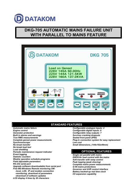
<strong>DKG</strong>-<strong>705</strong> AUTOMATIC MAINS FAILURE UNITWITH PARALLEL TO MAINS FEATUREAutomatic mains failureEngine controlGenerator protectionBuilt in alarms and warningsTrue RMS measurementsComplete genset power measurementsSynchronoscopeNo break transferNo break load testLoad sheddingPeriodic maintenance request indicatorEvent loggingStatistic countersWeekly operation schedule programsField adjustable parametersRS-232 serial portUpgrade software downloadable from serial portFree MS-Windows Remote monitoring SW:-local, LAN, IP and modem connection-monitoring, download of parameters-download of software updatesLCD display 4 lines by 20 charactersSTANDARD FEATURESConfigurable analogue inputs: 4Configurable digital inputs: 8Configurable relay outputs: 7Survives cranking dropoutsSealed front panel (IP65)Plug-in connection system for easy replacementLow costSmall dimensions, (144x192x49mm)OPTIONAL FEATURESSingle set parallel with mainsKW/KVAr load control with the mainsSoft transfer with ramp controlPeak lopping (peak shaving)Complete mains power measurementsG-59 mains protectionsGovernor and AVR control interfaceBattery backed-up real time clockI/O expansion capability
DESCRIPTIONThe <strong>DKG</strong>-<strong>705</strong> is a comprehensive <strong>AMF</strong> unit for a singlegenerating set operating in standby or parallel withmains modes. The unit has two option levels, thestandard version being for standby and the ‘full’ one forparallel with mains applications.In AUTOMATIC position, <strong>DKG</strong>-<strong>705</strong> monitors mainsphase voltages and controls the automatic starting,stopping and load transfer of the generating set in caseof a mains failure and once the generator is running, itmonitors internal protections and external fault inputs. Ifa fault condition occurs, the unit shuts down the engineautomatically, indicates the failure source on the LCDdisplay and turns on the red ALARM led.The <strong>DKG</strong>-<strong>705</strong> unit is able to transfer the load betweenmains and genset in 4 different ways:-transfer with interruption: there will be a powerinterruption period duration during the transfer-no break transfer without synchronization: transferwill be made without power interruption. The unit waitsuntil mains and generator phases match and makes aquick transfer.-no break transfer with synchronization (availableonly with ‘full’ version): transfer will be made withoutpower interruption. The unit operates the governor andAVR control outputs to synchronize the generator withthe mains and makes a quick transfer.-soft transfer (available only with ‘full’ version): transferwill be made without power interruption. The unitoperates the governor and AVR control outputs tosynchronize the generator with the mains and makes asmooth ramped transfer.The operation of the unit is controlled with front panelpushbuttons. The LOAD TEST, TEST, AUTO and OFFpushbuttons select the operating mode. Other buttonsselect the program mode entry/exit, display parameterscroll, alarm mute and lamp test functions.The <strong>DKG</strong>-<strong>705</strong> provides a comprehensive set of digitallyadjustable timers, threshold levels, input and outputconfigurations and operating sequences. Theunauthorized access to program parameters is preventedby a 3 level password system. All programs may bemodified via front panel pushbuttons, and do not requirean external unit.The fault conditions are considered in 3 categories asWarnings, Load-dumps and Alarms. Measured valueshave separate programmable limits for warning andalarm conditions.The service request indicator lamp turns on at theexpiration of either engine hours or time limits.It is possible to monitor the operation of the systemlocally or remotely with the WINDOWS based PC utilityprogram.The unit is designed for front panel mounting. It is fittedinto the cut-out with steel springs removed. Connectionsare made with 2 part plug and socket connectors.STANDARD MEASUREMENTSGenerator Volts: U-N, V-N, W-NGenerator Volts: U-V, V-W, W-UGenerator Amps: U, V, WGenerator KW: U, V, W, totalGenerator KVA: U, V, W, totalGenerator KVAr: U, V, W, totalGenerator pf: U, V, W, averageGenerator Frequency,Mains Volts: R-N, S-N, T-NMains Volts: R-S, S-T, T-RMains Frequency,Synchronoscope Phase AngleSynchronoscope Voltage Match U-RBattery VoltageEngine RPMEngine Coolant TemperatureEngine Oil PressureEngine Oil TemperatureEngine Fuel LevelOPTIONAL MEASUREMENTS (‘full’ version only)Mains Amps: R, S, TMains KW: R, S, T, totalMains KVA: R, S, T, totalMains KVAr: R, S, T, totalMains pf: R, S, T, averageSTATISTICSFollowing incremental counters provide statistics aboutpast performance of the generating set:Generator KWh, KVAh, KVArhEngine Hours RunEngine Hours to ServiceTime to ServiceNumber of Engine CranksNumber of Genset RunsNumber of Genset on LoadDIGITAL INPUTSThe unit has 8 fully configurable digital inputs. Eachinput has following programmable parameters:-input channel name: selectable from a list of 32,-alarm type: shutdown / load-dump / warning / no alarm-alarm polling: on engine running / always-latching / non-latching operation,-contact type: NO / NC-switching: BAT+ / BAT-ANALOG INPUTSEngine analog inputs are provided for followingfunctions:-Coolant temperature-Oil pressure-Oil temperature-Fuel levelThe analog inputs connect to resistive sender units toprovide precise and adjustable protection. The inputshave programmable sensor characteristics so that theyare suitable for any type and any brand of sensors.RELAY OUTPUTSThe unit provides 7 relay outputs with programmablefunctions, selectable from a list of 112 entries.In addition to genset control signals any specific alarminformation may be output as a relay contact.Using two <strong>DKG</strong>-<strong>705</strong> Relay Expansion Modules, thenumber of relays may be increased up to 23, 16 of thembeing volt-free contacts.
BUILT IN ALARMSUnder/Over Generator VoltsUnder/Over Generator FrequencyUnder/Over Engine RPMHigh Battery VoltageLow Fuel LevelHigh Oil TemperatureHigh Coolant TemperatureLow Oil PressureFail to StopFail to StartBUILT IN LOADDUMPSGenerator Reverse PowerGenerator Excess PowerOvercurrentBUILT IN WARNINGSUnder/Over Generator FrequencyUnder/Over Engine RPMSynchronization FailHigh Battery VoltageLow Battery VoltageLow Fuel LevelHigh Oil TemperatureHigh Coolant TemperatureLow Oil PressureMains Phase Sequence FailGenerator Phase Sequence FailCharge FailLow Battery VoltageAVR Control FailGovernor Control FailParallel Mains FailMains Reverse PowerMains Frequency FailNo Mains FrequencyROCOF df/dt FailVector Shift df/dt FailWEEKLY OPERATION SCHEDULEIn AUTO mode only, the unit offers the capability ofdefining a weekly operation schedule. Programmableparameters allow the genset to operate automaticallyonly in defined time limits of each weekday.The standard unit increments the clock with themicroprocessor crystal frequency. With a ‘full’ versionunit, the internal battery backed-up real time clock willallow more precise switching times.TELEMETRY AND REMOTE PROGRAMMINGThe <strong>DKG</strong>-<strong>705</strong> module provides the user with largetelemetry facilities via its standard RS-232 serial port.The unit can be either connected to a PC or a modemfor remote communication.The PC software offers local, Local Area Network(LAN), internet and modem operation capabilities.In local mode, the PC is directly connected to the<strong>DKG</strong>-<strong>705</strong>.In LAN mode, additionally to the local connected PC,all PCs located in the same LAN may use the remotemonitoring program.In internet mode, the local PC should have an internetconnection with its own IP address. Using a passwordsystem, the <strong>DKG</strong>-<strong>705</strong> may be monitored anywhere inthe world via internet.In modem mode, both the PC and the <strong>DKG</strong>-<strong>705</strong> willbe connected to modems. The connection will beestablished over the telephone network. Note that themodem mode is also compatible with LAN and internetmodes, so that the modem data may be served by PCfor reuse in the LAN or internet.The PC program is used for below purposes:-software download: the <strong>DKG</strong>-<strong>705</strong> unit’s software isdownloadable from serial port. This provides the userwith field upgrading capability to new versions.-parameter upload/download: program parametersmay be saved to the PC or downloaded from PC. Thisprovides the user with the capability of preparingstandard configurations for different applications andtaking backup copies of parameter values.-remote monitoring: all measured values, statisticsand event records may be visualized on the PC screen.The displays simulate analog meters with userselectable size, position, range and multiple zones withgreen, yellow and red colors. There are more than 60possible displays and the user may design his ownscreen selecting between them. The values are alsostored on disk for further analysis.-diagnostics and analysis: the daily evolution ofrecorded values may be displayed or printed in agraphical form. This provides the service personel withthe capability of examining the history of an eventualfault condition.The PC software detects automatically new versionsover the internet. A menu system will guide user if hedesires to download the new version.EVENT LOGGINGThe <strong>DKG</strong>-<strong>705</strong> records last 32 events with date and timestamp. Recorded events are:-alarms, load-dumps and warnings-generator on-load/off-load informationAn example record may be as follows:EVENT LOGGING 1217-08-04 14:48.58SHUTDOWN ALARMLOW OIL PRESS. SWITCH
TECHNICAL SPECIFICATIONSAlternator voltage: 300 V-AC (Ph-N)Alternator frequency: 0-200 Hz.Mains voltage: 300 V-AC (Ph-N)Mains frequency: 0-200 Hz.DC Supply Range:12V selection: 9.0 to 17.0 V-DC24V selection: 18.0 to 33.0 V-DC.Cranking dropouts: survives 0 V for 100ms.Typical Standby Current: 75 mA-DCMaximum Operating Current: 400 mA-DC (Relayoutputs open)Generator Contactor Relay Output: 16 A / 250VMains Contactor Relay Output: 16 A / 250VDC Relay Outputs: 10 A / 28VMagnetic pick-up voltage: 0.5 to 70 Vpk.Magnetic pick-up frequency: 20 KHz max.Gov Control Output: 0 – 10 V-DCAVR Control Output: 300 – 1500 ohms.Charge excitation current: 36mA @ 12V-DC.Analog input range: 0-5000 ohms.Serial port: RS-232, 9600 bauds, no parity, 1 bit stopOperating temp: -20°C to 70°C.Storage temp: -40°C to 80°C.Maximum humidity: 95% non-condensing.IP Protection: IP65 from front panel, IP30 from the rear.Dimensions: 192 x 144 x 49 mm (WxHxD)Panel Cut-out Dimensions: 187x139 mm minimum.Mounting: Front panel mounted with rear retaining steelspring.Weight: 800 g (approx.)Case Material: High Temperature ABS (UL94-V0, 110°C)Conformity (EU directives)-73/23/EEC and 93/68/EEC-89/336/EEC, 92/31/EEC and 93/68/EECNorms of reference:-EN 61010 (safety requirements)-EN 50081-2 (EMC requirements)-EN 50082-2 (EMC requirements)TYPICAL CONNECTIONSDATAKOM Electronics LimitedTel : +90-216-466 84 60Fax : +90-216-364 65 65e-mail : datakom@datakom.com.trhttp: www.datakom.com.tr