I Agree - Nearfield Systems Inc.
I Agree - Nearfield Systems Inc.
I Agree - Nearfield Systems Inc.
- No tags were found...

You also want an ePaper? Increase the reach of your titles
YUMPU automatically turns print PDFs into web optimized ePapers that Google loves.
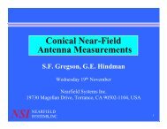
Overview• Prior work• Simulation scenario• SNF back projected data• Impact of radial distance variation• Impact of SNF angular span• Comparison with PNF data• ConclusionsJuly 2007 2
Prior work• Original high-resolution back projection formulation: M. G. Guler,E. B. Joy, "High resolution spherical microwave holography", IEEE Trans. APS,Vol. 43, May 1995, pp. 464 -472. Promised better performance than theplane wave equivalent.• Generalized to allow for back projection onto arbitrary planes: A.C. Newell, B. Schlüper & R. J. Davis, “Holographic Projection To An ArbitraryPlane From Spherical Near-Field Measurements”, AMTA Proceedings 2001,Denver, CO, Oct 2001. This formulation is implemented in the NSIsoftware.• Application of technique to microstrip array feed structure diagnostics:D. J. Janse van Rensburg & C. Walker, “Implementation of backprojection on a spherical near-field range”, AMTA Proceedings 2002.July 2007 3
Planar Near-field ScanJuly 2007 4
Coupling Equationr rDk ( , k) = t( k, k) • sk ( , k)x y x y x ye−iγd= ∫ 24πBxyde ( , , )− i( xk + yk )xydxdyRepresent the measured planar near-field data on the plane z = d asB(x,y,d) where x,y defines the position of the probe on themeasurement plane. From the near-field data we first compute theplane wave spectrum of the measured data using a Fourier transform.July 2007 5
Back Projection( )( , , ) ( , )iγ d hi xkx+ykyI h A x y x yB x y d = ∫ t k k e e dk dkBack projection is calculated on a plane removed from themeasurement plane by d h.July 2007 6
<strong>Nearfield</strong> and Hologram Back-projectionMeasured phase of THAADarray at .3m distance with25,344 active elements with 6bit phase shifter, 6 bit attenuatorin special ‘calibration’ modeNFHOLOJuly 2007 7
Far-field Expressionst ( k , k )A x y=Ε( k , k )A x yCos( θ )t ( k , k ) =E x yΕ( k , k )E x yCos( θ )July 2007 8
Far-field Expressions – Arbitrary Planert,( θφ)=rΕ,( θ φ )cosΘ( )cos( )Θ =rkrkv• em⎡sin( θ)cos( φ)⎤ ⎡sin( θm)cos( φm)⎤=⎢sin( θ)sin( φ) ⎥ ⎢sin( θm)sin( φm)⎥⎢ ⎥• ⎢ ⎥⎢⎣ cos( θ ) ⎥⎦ ⎢⎣ cos( θm)⎥⎦( m) ( m)( m) ( m)( θ ) θ= sin θ cos φ sin( θ)cos( φ)+ sin θ sin φ sin( θ)sin( φ)− cos cos( )mJuly 2007 9
Simulated array radiators.13 Elements21 ElementsJuly 2007 11
Array element size and spacing0.5 lambdaAmp = 1VPhase = 0 deg13 Elements0.4 lambda0.5 lambda21 ElementsJuly 2007 12
Orthogonal near-field pattern cutsNear-field amplitude of Array03_003.dat0HcutVcut-5-10-15Amplitude (dB)-20-25-30-35-40-45-50-0.20 -0.15 -0.10 -0.05 0.00 0.05 0.10 0.15 0.20X (meters)July 2007 13
Principal plane pattern cutsFar-field amplitude of Array03_023.dat0HcutVcut-5-10-15Amplitude (dB)-20-25-30-35-40-45-50-60 -50 -40 -30 -20 -10 0 10 20 30 40 50 60Azimuth (deg)July 2007 14
Single element with reversed phase13 Elements21 ElementsJuly 2007 15
PNF phase distribution for back projection0.15Hologram phase of Array04_003.datY (meters)0.100.050.00-0.05-0.101801701601501401301201101009080706050403020100-10-20-30-40-50-60-70-80-90-100-110-120-130-140-150-160-170-180-0.15-0.20 -0.15 -0.10 -0.05 0.00 0.05 0.10 0.15 0.20X (meters)July 2007 16
SNF Radial Distance Sensitivity I• SNF back projection resolution is independent of distance betweenAUT and probe• Holds a significant advantage over PNF method• Will in practice be limited by instrumentation dynamic rangeHologram amplitude of SNF_sim_21x13_Array_One_element_phase_rev.nsiHologram amplitude of SNF_sim_21x13_Array_One_element_phase_rev2.nsi0.300.300.2000.200-1-1-2-2-3-30.10-4-50.10-4-5-6-6Y (meters)0.00-7-8-9-10-11-12-13Y (meters)0.00-7-8-9-10-11-12-13-0.10-14-15-0.10-14-15-16-16-17-17-18-18-0.20-19-20-0.20-19-20-0.30-0.30 -0.20 -0.10 0.00 0.10 0.20 0.30-0.30-0.30 -0.20 -0.10 0.00 0.10 0.20 0.30X (meters)X (meters)July 2007 17
SNF Radial Distance Sensitivity II• NF data shown below for three separate data setsNear-field amplitude of SNF_sim_21x13_Array_One_element_phase_rev2.nsiSNF_sim_21x13_Array_One_element_phase_rev.nsiHologram amplitude of SNF_sim_21x13_Array_One_element_phase_rev2.nsi0R=0.4m R=0.8m R=0.8m R=1.8m R=1.8m0.0R=0.8mR=1.8m-5-2.5-10-15-5.0Amplitude (dB)-20-25-30Amplitude (dB)-7.5-10.0-12.5-35-40-15.0-45-17.5-50-150 -100 -50 0 50 100 150Theta (deg)-20.0-0.30 -0.25 -0.20 -0.15 -0.10 -0.05 0.00 0.05 0.10 0.15 0.20 0.25 0.30X (meters)July 2007 18
SNF Angular Span Sensitivity• < Hemi-spherical data set limits back projection resolution• Data shows effect of phase reversal of single elementexcitationHologram phase of SNF_sim_21x13_Array_One_element_phase_rev3.nsiHologram amplitude of SNF_sim_21x13_Array_One_element_phase_rev3.nsiSphere Hemi 160deg 120deg 800.0Sphere Hemi 160deg 120deg 80150-2.5100-5.050-7.5Phase (deg)0-50Amplitude (dB)-10.0-12.5-100-15.0-17.5-150-20.0-0.30 -0.25 -0.20 -0.15 -0.10 -0.05 0.00 0.05 0.10 0.15 0.20 0.25 0.30X (meters)-0.30 -0.25 -0.20 -0.15 -0.10 -0.05 0.00 0.05 0.10 0.15 0.20 0.25 0.30X (meters)July 2007 19
SNF Angular Span Sensitivity – cont’d.• AmplitudeHologram amplitude of SNF_sim_21x13_Array_One_element_phase_rev3.nsiSphere Hemi sphere 160deg120deg80deg0-5-10Amplitude (dB)-15-20-25-30-0.25 -0.20 -0.15 -0.10 -0.05 0.00 0.05 0.10 0.15 0.20 0.25X (meters)July 2007 20
SNF Angular Span Sensitivity – cont’d.Hologram phase of SNF_sim_21x13_Array_One_element_phase_rev3.nsi• Phase100Sphere Hemi sphere 160deg120deg80deg500Phase (deg)-50-100-150-0.30 -0.25 -0.20 -0.15 -0.10 -0.05 0.00 0.05 0.10 0.15 0.20 0.25 0.30X (meters)July 2007 21
PNF Probe to AUT separation distanceAmplitude of the backprojected data fordifferent probe to AUTseparation distances.Dip should be at60mm.0.0-2.5-5.0Hologram amplitude of Array04_003.dat0 Lmbd 1 Lmbd 2 Lmbd 3 Lmbd 5 LmbdAmplitude (dB)-7.5-10.0-12.5-15.0-0.075 -0.050 -0.025 0.000 0.025 0.050 0.075X (meters)July 2007 22
PNF Probe to AUT separation distance IIPhase of the backprojected data fordifferent probe to AUTseparation distances.Dip should be at20mm.0-10-20-30-40Hologram phase of Array04_003.dat0 Lmbd 1 Lmbd 2 Lmbd 3 Lmbd 5 LmbdPhase (deg)-50-60-70-80-90-100-0.05 -0.04 -0.03 -0.02 -0.01 0.00 0.01 0.02 0.03 0.04 0.05Y (meters)July 2007 23
SNF Amplitude sensitivity IHologram amplitude of SNF_sim_21x13_Array.nsiAmplitude changein the backprojected field forexcitationamplitude changeof a single arrayelement.Amplitude (dB)0-1-2-3-4-5-6Ref 0.5dB 1dB 3dB 10dB-7-8-9-10-0.20 -0.15 -0.10 -0.05 0.00 0.05 0.10 0.15 0.20X (meters)July 2007 24
PNF Amplitude sensitivity IHologram amplitude of Array09_063.datAmplitude changein the backprojected field forexcitationamplitude changeof a single arrayelement.Amplitude (dB)0.0-0.5-1.0-1.5-2.0-2.5-3.0Ref 0.5dB 1dB 3dB 10dB-3.5-4.0-4.5-5.0-0.075 -0.050 -0.025 0.000 0.025 0.050 0.075X (meters)July 2007 25
SNF Amplitude sensitivity IIHologram amplitude of SNF_sim_21x13_Array.nsiAmplitude changein the backprojected field forexcitationamplitude changeof a single arrayelement.Amplitude (dB)0-1-2-3-4-5-6Ref 0.5dB 1dB 3dB 10dB-7-8-9-10-0.20 -0.15 -0.10 -0.05 0.00 0.05 0.10Y (meters)July 2007 26
PNF Amplitude sensitivity IIHologram amplitude of Array09_063.datAmplitude changein the backprojected field forexcitationamplitude changeof a single arrayelement.Amplitude (dB)0.0-0.5-1.0-1.5-2.0-2.5-3.0Ref 0.5dB 1dB 3dB 10dB-3.5-4.0-4.5-5.0-0.05 -0.04 -0.03 -0.02 -0.01 0.00 0.01 0.02 0.03 0.04 0.05Y (meters)July 2007 27
SNF Phase sensitivityPhase change in theback projected fieldfor excitation phasechange of a singlearray element.Hologram phase of SNF_sim_21x13_Array.nsi-100Ref 1deg 10deg 30deg-105-110-115Phase (deg)-120-125-130-135-140-0.25 -0.20 -0.15 -0.10 -0.05 0.00 0.05 0.10 0.15 0.20 0.25X (meters)July 2007 28
Conclusions I• SNF back projection resolution does NOT degradewhen probe to AUT distance is increased.• Back projection resolution DOES degrade whenangular span is reduced to < hemi-sphere of data.• Small changes in the array excitation vector can bedetected.July 2007 29
Conclusions II• SNF holds advantage over PNF due to largerprobe/AUT separation distance.• Spherical wave expansion theory can be applied totraditional roll/azimuth far-field ranges.July 2007 30
Limitations• The data presented here relies on the use of aninfinitesimal point “probe” and the effect of the probe, aswould be present in an actual measurement environment,is absent.• Instrumentation dynamic range limitation will affectresults.July 2007 31