HX8340B(N) (datasheet) - Adafruit
HX8340B(N) (datasheet) - Adafruit
HX8340B(N) (datasheet) - Adafruit

Create successful ePaper yourself
Turn your PDF publications into a flip-book with our unique Google optimized e-Paper software.
DATA SHEET( DOC No. HX8340-B(T)-DS )HX8340-B(T)176RGB x 220 dot, 262k color,with internal GRAM,TFT Mobile Single Chip DriverPreliminary version 01 February, 2008
HX8340-B(T)176RGB x 220 dot, 262K color, with internalGRAM, TFT Mobile Single Chip DriverList of Contents February, 20081. General Description..................................................................................................................................... 82. Features........................................................................................................................................................ 93. Block Diagram.............................................................................................................................................114. Pin Description .......................................................................................................................................... 124.1 Pin Description..................................................................................................................................... 124.2 Pin Assignment .................................................................................................................................... 174.3 Pad Coordinates................................................................................................................................... 184.4 Alignment Mark .................................................................................................................................... 234.5 Bump Size............................................................................................................................................. 245. Interface...................................................................................................................................................... 255.1 System Interface Circuit...................................................................................................................... 265.1.1 Parallel Bus System Interface ......................................................................................................... 275.1.2 MCU Data Color Coding.................................................................................................................. 305.1.3 MCU Data Color Coding for RAM Data Read ................................................................................. 455.1.4 Serial Bus System Interface............................................................................................................ 505.1.5 Color Depth Conversion Look-up Tables ........................................................................................ 525.2 RGB Interface ....................................................................................................................................... 545.2.1 Color Order on RGB Interface......................................................................................................... 585.2.2 RGB Data Color Coding .................................................................................................................. 596. Display Data GRAM ................................................................................................................................... 626.1 Display Data GRAM Mapping.............................................................................................................. 626.2 Address Counter (AC) of GRAM ......................................................................................................... 636.2.1 System Interface to GRAM Write Direction..................................................................................... 646.3 GRAM to Display Address Mapping................................................................................................... 696.3.1 Normal Display On or Partial Mode On, Vertical Scroll Off ............................................................. 716.3.2 Vertical Scroll Display Mode............................................................................................................ 746.3.3 Updating Order on Display Active Area in RGB Interface Mode ..................................................... 777. Functional Description.............................................................................................................................. 807.1 Internal Oscillator................................................................................................................................. 807.2 Gamma Characteristic Correction Function ..................................................................................... 817.3 Tearing Effect Output Line .................................................................................................................. 907.3.1 Tearing Effect Line Modes ............................................................................................................... 907.3.2 Tearing Effect Line Timing ............................................................................................................... 917.3.3 Example 1: MPU Write is faster than Panel Read .......................................................................... 927.3.4 Example 2: MPU Write is slower than Panel Read ......................................................................... 937.4 LCD Power Generation Circuit ........................................................................................................... 947.4.1 Power Supply Circuit ....................................................................................................................... 947.4.2 LCD Power Generation Scheme..................................................................................................... 967.5 Power Function .................................................................................................................................... 977.5.1 System Interface Power On/Off Sequence ..................................................................................... 977.5.2 RGB Interface Power On/Off......................................................................................................... 1007.6 Input / Output Pin State ..................................................................................................................... 1027.6.1 Output Pins.................................................................................................................................... 1027.6.2 Input Pins....................................................................................................................................... 1028. Command Set........................................................................................................................................... 1038.1 Command Description....................................................................................................................... 1038.2 Index Register .................................................................................................................................... 1068.3 Display Mode Control Register (R01h) ............................................................................................ 106Himax Confidential-P.1-This information contained herein is the exclusive property of Himax and shall not be distributed, reproduced, or disclosedin whole or in part without prior written permission of Himax. February, 2008
HX8340-B(T)176RGB x 220 dot, 262K color, with internalGRAM, TFT Mobile Single Chip DriverList of Contents February, 20088.4 Column Address Start Register (R02~03h) ..................................................................................... 1078.5 Column Address End Register (R04~05h)....................................................................................... 1078.6 Row Address Start Register (R06~07h) ........................................................................................... 1078.7 Row Address End Register (R08~09h)............................................................................................. 1088.8 Partial Area Start Row Register (R0A~0Bh) .................................................................................... 1098.9 Partial Area End Row Register (R0C~0Dh)...................................................................................... 1098.10 Vertical Scroll Top Fixed Area Register (R0E~0Fh) ....................................................................... 1118.11 Vertical Scroll Height Area Register (R10~11h).............................................................................. 1118.12 Vertical Scroll Button Fixed Area Register (R12~13h) .................................................................. 1118.13 Vertical Scroll Start Address Register (R14~15h) ..........................................................................1138.14 Memory Access Control Register (R16h) .......................................................................................1158.15 COLMOD Control Register (R17h)...................................................................................................1168.16 OSC Control Register (R18h & R21h) .............................................................................................1178.17 Power Control 1 Register (R19h).....................................................................................................1188.18 Power Control 2 Register (R1Ah) ....................................................................................................1198.19 Power Control 3 Register (R1Bh) ................................................................................................... 1208.20 Power Control 4 Register (R1Ch) ................................................................................................... 1218.21 Power Control 5 Register (R1Dh) ................................................................................................... 1218.22 Power Control 6 Register (R1Eh) ................................................................................................... 1218.23 Power Control 7 Register (R1Fh).................................................................................................... 1228.24 Power Control 8 Register (R20h).................................................................................................... 1238.25 Write/Read Data Register (R22h) .................................................................................................... 1248.26 VCOM Offset Control Register (R23h) ........................................................................................... 1258.27 VCOMH Control Register (R24h) .................................................................................................... 1268.28 VCOML Control Register (R25h)..................................................................................................... 1278.29 Display Control 1 Register (R26h).................................................................................................. 1288.30 Display Control 2 Register (R27h).................................................................................................. 1298.31 Frame Rate Control Register (R28h~R2Bh) .................................................................................. 1308.32 Display Cycle Control Register (R2Ch~R2Eh) .............................................................................. 1328.33 Display Inversion Control Register (R2Fh) ................................................................................... 1338.34 RGB Interface Control Register (R31h~R32h)............................................................................... 1348.35 RGB Interface Signal Control Register (R33h).............................................................................. 1358.36 RGB Interface Power on/off Control Register (R34h)................................................................... 1358.37 RGB Interface Output Direction Register (R35h).......................................................................... 1368.38 Interface Mode Selection Register (R36h)..................................................................................... 1368.39 Normally White/Black Control Register (R37h)............................................................................. 1378.40 OTP Register (R38h ~ R3Ah)........................................................................................................... 1378.41 Positive Gamma Control (R40h~R48h) .......................................................................................... 1388.42 Negative Gamma Control (R50h~R57h)......................................................................................... 1398.43 Display Control Internal Used (R59h) ............................................................................................ 1418.43 Power Control Internal Used (R60h~R63h) ................................................................................... 1418.44 Source OP Control (R73h)............................................................................................................... 1428.45 Himax ID (R93h)................................................................................................................................ 1429. Layout Recommendation........................................................................................................................ 1439.1 Parallel Interface of Register-Content Mode ................................................................................... 1439.2 RGB + SPI Interface of Register-Content ........................................................................................ 14410. OTP.......................................................................................................................................................... 14511. Electrical Characteristic........................................................................................................................ 14711.1 Absolute Maximum Ratings ............................................................................................................ 14711.2 ESD Protection Level....................................................................................................................... 14711.3 Latch-Up Protection Level............................................................................................................... 14711.4 Light Sensitivity................................................................................................................................ 14711.5 Maximum Layout Resistance.......................................................................................................... 148Himax ConfidentialThis information contained herein is the exclusive property of Himax and shall not be distributed, reproduced, or disclosedin whole or in part without prior written permission of Himax.-P.2-February, 2008
HX8340-B(T)176RGB x 220 dot, 262K color, with internalGRAM, TFT Mobile Single Chip DriverList of Contents February, 200811.6 DC Characteristics ........................................................................................................................... 14911.6.1 Current Consumption................................................................................................................... 15011.7 AC Characteristics ........................................................................................................................... 15111.7.1 Parallel Interface Characteristics (8080-Series MPU)................................................................. 15111.7.2 Parallel Interface Characteristics (6800-Series MPU)................................................................. 15311.7.3 Serial Interface Characteristics.................................................................................................... 15411.7.4 RGB Interface Characteristics ..................................................................................................... 15511.7.5 Reset Input Timing....................................................................................................................... 15711.7.6 Measurement Conditions............................................................................................................. 15812. Ordering Information............................................................................................................................. 16013. Revision History .................................................................................................................................... 160Himax ConfidentialThis information contained herein is the exclusive property of Himax and shall not be distributed, reproduced, or disclosedin whole or in part without prior written permission of Himax.-P.3-February, 2008
HX8340-B(T)176RGB x 220 dot, 262K color, with internalGRAM, TFT Mobile Single Chip DriverList of Figures February, 2008Figure 5. 1 Register Read/Write Timing in Parallel Bus System Interface (for I80 Series MPU)...... 28Figure 5. 2 GRAM Read/Write Timing in Bit Parallel Bus System Interface (for I80 Series MPU) ... 28Figure 5. 3 Register Read/Write Timing in Parallel Bus System Interface (for M68 Series MPU).... 29Figure 5. 4 GRAM Read/Write Timing in Bit Parallel Bus System Interface (for M68 Series MPU) . 29Figure 5. 5 Example of I80- / M68- System 8-Bit Parallel Bus Interface........................................... 31Figure 5. 6 8-bit data bus for 12-bits/pixel......................................................................................... 32Figure 5. 7 8-bit data bus for 16-bits/pixel......................................................................................... 33Figure 5. 8 8-bit data bus for 18-bits/pixel......................................................................................... 34Figure 5. 9 Example of I80- / M68- System 16-Bit Parallel Bus Interface......................................... 35Figure 5. 10 16-bit data bus for 12-bits/pixel..................................................................................... 36Figure 5. 11 16-bit data bus for 16-bits/pixel ..................................................................................... 37Figure 5. 12 16-bit data bus for 18-bits/pixel..................................................................................... 38Figure 5. 13 Example of I80- / M68- System 9-Bit Parallel Bus Interface......................................... 39Figure 5. 14 9-bit data bus for 18-bits/pixel....................................................................................... 40Figure 5. 15 Example of I80- / M68- System 18-Bit Parallel Bus Interface....................................... 41Figure 5. 16 18-bit data bus for 12-bits/pixel..................................................................................... 42Figure 5. 17 18-bit data bus for 16-bits/pixel..................................................................................... 43Figure 5. 18 18-bit data bus for 18-bits/pixel..................................................................................... 44Figure 5. 19 8-bit data bus for RAM data read.................................................................................. 46Figure 5. 20 16-bit data bus for RAM data read................................................................................ 47Figure 5. 21 9-bit data bus for RAM data read.................................................................................. 48Figure 5. 22 18-bit data bus for RAM data read................................................................................ 49Figure 5. 23 Index Register Read/Write Timing in Serial Bus System Interface............................... 50Figure 5. 24 Data Write Timing in Serial Bus System Interface........................................................ 51Figure 5. 25 DOTCLK Cycle ............................................................................................................. 54Figure 5. 26 RGB Interface Circuit Input Timing Diagram................................................................. 55Figure 5. 27 RGB Mode timing Diagram........................................................................................... 56Figure 5. 28 RGB 18-bits/pixel on 6-bits Data width ......................................................................... 59Figure 5. 29 RGB 16-bits/pixel on 16-bits Data width ....................................................................... 60Figure 5. 30 RGB 18-bits/pixel on 18-bits Data width ....................................................................... 61Figure 6. 1 Image Data Sending Order from the Host ...................................................................... 64Figure 6. 2 Image Data Writing Control............................................................................................. 64Figure 6. 3 Example for Rotation with MY, MX and MV – 1 ............................................................. 67Figure 6. 4 Example for Rotation with MY, MX and MV - 2 .............................................................. 68Figure 6. 5 Example of Partial Mode on (ML=’0’).............................................................................. 72Figure 6. 6 Example of Partial Mode on (ML=’1’).............................................................................. 72Figure 6. 7 Vertical Scrolling ............................................................................................................. 74Figure 6. 8 Memory Map of Vertical Scrolling I ................................................................................. 74Figure 6. 9 Memory Map of Vertical Scrolling II ................................................................................ 75Figure 6. 10 Memory Map of Vertical Scrolling III ............................................................................. 75Figure 6. 11 Vertical Scroll Example when ML=’0’............................................................................ 76Figure 6. 12 Vertical Scroll Example when ML=’1’............................................................................ 76Figure 6. 13 Data Streaming Order in RGB I/F................................................................................. 77Figure 6. 14 Updating Order when TB = ‘L’ and RL = ‘L’.................................................................. 78Figure 6. 15 Updating Order when TB = ‘L’ and RL = ‘H’ ................................................................. 78Figure 6. 16 Updating Order when TB = ‘H’ and RL = ‘L’ ................................................................. 79Figure 6. 17 Updating Order when TB = ‘H’ and RL = ‘H’................................................................. 79Figure 7. 1 HX8340-B Internal Clock Circuit ..................................................................................... 80Figure 7. 2 Grayscale Control ........................................................................................................... 81Figure 7. 3 Structure of Grayscale Voltage Generator...................................................................... 82Figure 7. 4 Gamma Resister Stream and Gamma Reference Voltage ............................................ 84Figure 7. 5 Relationship between Source Output and VCOM .......................................................... 89Himax Confidential-P.4-This information contained herein is the exclusive property of Himax and shall not be distributed, reproduced, or disclosedin whole or in part without prior written permission of Himax. February, 2008
HX8340-B(T)176RGB x 220 dot, 262K color, with internalGRAM, TFT Mobile Single Chip DriverList of Figures February, 2008Himax ConfidentialFigure 7. 6 Relationship between GRAM Data and Output Level (Normal White Panel andINVON=“0”) ................................................................................................................................ 89Figure 7. 7 TE mode 1 output ........................................................................................................... 90Figure 7. 8 TE mode 2 output ........................................................................................................... 90Figure 7. 9 TE output waveform........................................................................................................ 90Figure 7. 10 Waveform of Tearing Effect Signal ............................................................................... 91Figure 7. 11 Timing of Tearing Effect Signal..................................................................................... 91Figure 7. 12 The Block Diagram of HX8340-B Power Circuit ........................................................... 94Figure 7. 13 LCD Power Generation Scheme .................................................................................. 96Figure 7. 14 Display On/Off Set flow................................................................................................. 97Figure 7. 15 Standby Mode Setting flow ........................................................................................... 98Figure 7. 16 Power Supply Setting Flow........................................................................................... 99Figure 7. 17 Power On Sequence on RGB..................................................................................... 100Figure 7. 18 Power off Sequence on RGB Mode............................................................................ 101Figure 8. 1 Index Register............................................................................................................... 106Figure 8. 2 Display Mode Control Register (R01h) ......................................................................... 106Figure 8. 3 Column Address Start Register Upper Byte (R02h) ..................................................... 107Figure 8. 4 Column Address Start Register Low Byte (R03h) ........................................................ 107Figure 8. 5 Column Address End Register Upper Byte (R04h) ...................................................... 107Figure 8. 6 Column Address End Register Low Byte (R05h) ......................................................... 107Figure 8. 7 Row Address Start Register Upper Byte (R06h) .......................................................... 107Figure 8. 8 Row Address Start Register Low Byte (R07h).............................................................. 107Figure 8. 9 Row Address End Register Upper Byte (R08h) ........................................................... 108Figure 8. 10 Row Address End Register Low Byte (R09h)............................................................. 108Figure 8. 11 Partial Area Start Row Register Upper Byte (R0Ah)................................................... 109Figure 8. 12 Partial Area Start Row Register Low Byte (R0Bh) ..................................................... 109Figure 8. 13 Partial Area End Row Register Upper Byte (R0Ch) ................................................... 109Figure 8. 14 Partial Area End Row Register Low Byte (R0Dh) ...................................................... 109Figure 8. 15 Vertical Scroll Top Fixed Area Register Upper Byte (R0Eh) ....................................... 111Figure 8. 16 Vertical Scroll Top Fixed Area Register Low Byte (R0Fh)........................................... 111Figure 8. 17 Vertical Scroll Height Area Register Upper Byte (R10h) ............................................. 111Figure 8. 18 Vertical Scroll Height Area Register Low Byte (R11h) ................................................ 111Figure 8. 19 Vertical Scroll Button Fixed Area Register Upper Byte (R12h) ................................... 111Figure 8. 20 Vertical Scroll Button Fixed Area Register Low Byte (R13h)....................................... 111Figure 8. 21 Vertical Scroll Start Address Register Upper Byte (R14h) ..........................................113Figure 8. 22 Vertical Scroll Start Address Register Low Byte (R15h)..............................................113Figure 8. 23 Memory Access Control Register (R16h) ....................................................................115Figure 8. 24 COLMOD Control Register (R16h) ..............................................................................116Figure 8. 25 OSC Control 1 Register (R18h) ...................................................................................117Figure 8. 26 OSC Control 2 Register (R21h) ...................................................................................117Figure 8. 27 Power Control 1 Register (R19h).................................................................................118Figure 8. 28 Power Control 2 Register (R1Ah) ................................................................................119Figure 8. 29 Power Control 3 Register (R1Bh) ............................................................................... 120Figure 8. 30 Power Control 4 Register (R1Ch) ............................................................................... 121Figure 8. 31 Power Control 5 Register (R1Dh) ............................................................................... 121Figure 8. 32 Power Control 6 Register (R1Eh) ............................................................................... 121Figure 8. 33 Power Control 7 Register (R1Fh) ............................................................................... 122Figure 8. 34 Power Control 8 Register (R20h)................................................................................ 123Figure 8. 35 Read Data Register (R22h) ........................................................................................ 124Figure 8. 36 VCOM Offset Control Register (R23h) ....................................................................... 125Figure 8. 37 VCOMH Control Register (R24h) ............................................................................... 126Figure 8. 38 VCOML Control Register (R25h) ................................................................................ 127Figure 8. 39 Display Control 1 Register (R26h) .............................................................................. 128Figure 8. 40 Display Control 2 Register (R27h) .............................................................................. 129This information contained herein is the exclusive property of Himax and shall not be distributed, reproduced, or disclosedin whole or in part without prior written permission of Himax.-P.5-February, 2008
HX8340-B(T)176RGB x 220 dot, 262K color, with internalGRAM, TFT Mobile Single Chip DriverList of Figures February, 2008Figure 8. 41 Frame Control 1 Register (R28h) ............................................................................... 130Figure 8. 42 Frame Control 2 Register (R29h) ............................................................................... 130Figure 8. 43 Frame Control 3 Register (R2Ah) ............................................................................... 130Figure 8. 44 Frame Control 4 Register (R2Bh) ............................................................................... 130Figure 8. 45 Display Cycle Control 1 Register (R2Ch) ................................................................... 132Figure 8. 46 Display Cycle Control 2 Register (R2Dh) ................................................................... 132Figure 8. 47 Display Cycle Control 1 Register (R2Eh).................................................................... 132Figure 8. 48 Display Inversion Control Register (R2Fh) ................................................................. 133Figure 8. 49 RGB Interface HBP Control Register (R31h).............................................................. 134Figure 8. 50 RGB Interface VBP Control Register (R32h).............................................................. 134Figure 8. 51 RGB Interface Signal Control Register (R33h)........................................................... 135Figure 8. 52 RGB Interface Power On/Off Control Register (R34h) ............................................... 135Figure 8. 53 RGB Interface Output Direction Control Register (R35h)........................................... 136Figure 8. 54 Interface Mode Selection Control Register (R36h)..................................................... 136Figure 8. 55 Normally White/Black Control Register (R37h) .......................................................... 137Figure 8. 56 OTP Command 1 (R38h) ............................................................................................ 137Figure 8. 57 OTP Command 2 (R39h) ............................................................................................ 137Figure 8. 58 OTP Command 3 (R3Ah)............................................................................................ 137Figure 8. 59 Positive Gamma Control 1 Register (R40h) ............................................................... 138Figure 8. 60 Positive Gamma Control 2 Register (R41h) ............................................................... 138Figure 8. 61 Positive Gamma Control 3 Register (R42h) ............................................................... 138Figure 8. 62 Positive Gamma Control 4 Register (R43h) ............................................................... 138Figure 8. 63 Positive Gamma Control 5 Register (R44h) ............................................................... 138Figure 8. 64 Positive Gamma Control 6 Register (R45h) ............................................................... 138Figure 8. 65 Positive Gamma Control 7 Register (R46h) ............................................................... 138Figure 8. 66 Positive Gamma Control 8 Register (R47h) ............................................................... 139Figure 8. 67 Positive Gamma Control 9 Register (R48h) ............................................................... 139Figure 8. 68 Negative Gamma Control 1 Register (R50h).............................................................. 139Figure 8. 69 Negative Gamma Control 2 Register (R51h).............................................................. 139Figure 8. 70 Negative Gamma Control 3 Register (R52h).............................................................. 139Figure 8. 71 Negative Gamma Control 4 Register (R53h).............................................................. 139Figure 8. 72 Negative Gamma Control 5 Register (R54h).............................................................. 139Figure 8. 73 Negative Gamma Control 6 Register (R55h).............................................................. 140Figure 8. 74 Negative Gamma Control 7 Register (R56h).............................................................. 140Figure 8. 75 Negative Gamma Control 8 Register (R57h).............................................................. 140Figure 8. 76 Display Control Internal used Register (R59h) ........................................................... 141Figure 8. 76 Power Control Internal used (1) Register (R60h) ....................................................... 141Figure 8. 77 Power Control Internal used (2) Register (R61h) ....................................................... 141Figure 8. 78 Source Control Internal used (1) Register (R62h) ...................................................... 141Figure 8. 79 Source Control Internal used (2) Register (R63h) ...................................................... 141Figure 8. 80 Source OP Control Register (R73h) ........................................................................... 142Figure 8. 81 Himax ID Register (R93h)........................................................................................... 142Figure 9. 1 Layout Recommendation of System Interface.............................................................. 143Figure 9. 2 Layout Recommendation of RGB Interface.................................................................. 144Figure 11. 1 Parallel Interface Characteristics (8080-Series MPU) ................................................ 151Figure 11. 2 Chip Select Timing ...................................................................................................... 152Figure 11. 3 Write to Read and Read to Write Timing .................................................................... 152Figure 11. 4 Parallel Interface Characteristics (6800-Series MPU) ................................................ 153Figure 11. 5 Serial Interface Characteristics ................................................................................... 154Figure 11. 6 Reset Input Timing ...................................................................................................... 157Himax ConfidentialThis information contained herein is the exclusive property of Himax and shall not be distributed, reproduced, or disclosedin whole or in part without prior written permission of Himax.-P.6-February, 2008
HX8340-B(T)176RGB x 220 dot, 262K color, with internalGRAM, TFT Mobile Single Chip DriverList of Tables February, 2008Table 5. 1 Pin connection According to MCU Interface Type Selection ............................................ 26Table 5. 2 Data Pin Function for I80 Series CPU.............................................................................. 27Table 5. 3 Data Pin Function for M68 Series CPU............................................................................ 27Table 5. 4 8-Bits Parallel Interface Set Table .................................................................................... 30Table 5. 5 16-Bits Parallel Interface Set Table .................................................................................. 30Table 5. 6 9-Bits Parallel Interface Set Table .................................................................................... 30Table 5. 7 18-Bits Parallel Interface Set Table .................................................................................. 30Table 5. 8 8-Bits Parallel Interface Set Table .................................................................................... 45Table 5. 9 16-Bits Parallel Interface Set Table .................................................................................. 45Table 5. 10 9-Bits Parallel Interface Set Table .................................................................................. 45Table 5. 11 18-Bits Parallel Interface Set Table................................................................................. 45Table 5. 12 The Function of RS and R/W Bit .................................................................................... 50Table 5. 13 Look-up Tables for 4k Color Mode ................................................................................. 52Table 5. 14 Look-up Tables for 65k Color Mode ............................................................................... 53Table 5. 15 RGB interface Bus Width Set Table................................................................................ 57Table 5. 16 Meaning of the Pixel Information for Main Colors on RGB Interface ............................. 58Table 6. 1 GRAM Address for Display Panel Position....................................................................... 62Table 6. 2 CASET and PASET Control for Physical Column/Page Pointers .................................... 64Table 6. 3 Rules for Updating GRAM Order...................................................................................... 65Table 6. 4 Address Direction Settings ............................................................................................... 66Table 6. 5 GRAM X Address and Display Panel Position ................................................................. 69Table 6. 6 GRAM Address and Display Panel Position (SMY =’L’) ................................................... 70Table 6. 7 GRAM Address and Display Panel Position (SMY =’H’) .................................................. 70Table 6. 8 ISC[3:0] Bits Definition...................................................................................................... 73Table 6. 9 Rules for Updating Order on Display Active Area in RGB Interface Display Mode.......... 79Table 7. 1 Gamma-Adjustment Registers ......................................................................................... 83Table 7. 2 Offset Adjustment 0 ........................................................................................................ 85Table 7. 3 Offset Adjustment 1 .......................................................................................................... 85Table 7. 4 Center Adjustment............................................................................................................ 85Table 7. 5 Output Voltage of 8 to 1 Selector ..................................................................................... 86Table 7. 6 Voltage Calculation Formula ............................................................................................ 87Table 7. 7 Voltage Calculation Formula of Grayscale Voltage.......................................................... 88Table 7. 8 Voltage Calculation Formula of Grayscale Voltage V2~V7 and V56~V61....................... 88Table 7. 9 AC characteristics of Tearing Effect Signal ...................................................................... 91Table 7. 10 The adoptability of Capacitor and Diode ........................................................................ 95Table 7. 11 Power ON AC Characteristics....................................................................................... 100Table 7. 12 Power off AC Characteristics........................................................................................ 101Table 7. 13 Characteristics of Output Pins...................................................................................... 102Table 7. 14 Characteristics of Input Pins......................................................................................... 102Table 10. 1 OTP ADDRESS MAPPING .......................................................................................... 145Table 11. 1 Absolute Maximum Ratings .......................................................................................... 147Himax Confidential-P.7-This information contained herein is the exclusive property of Himax and shall not be distributed, reproduced, or disclosedin whole or in part without prior written permission of Himax. February, 2008
HX8340-B(T)176RGB x 220 dot, 262K color, with internalGRAM, TFT Mobile Single Chip DriverPreliminary Version 01 February, 20081. General DescriptionThis document describes HX8340-B 176RGBx220 dots resolution driving controller. TheHX8340-B is designed to provide a single-chip solution that combines a gate driver, a sourcedriver, power supply circuit for 262,144 colors to drive a TFT panel with 176RGBx220 dots atmaximum.The HX8340-B can be operated in low-voltage (1.65V) condition for the interface and integratedinternal boosters that produce the liquid crystal voltage, breeder resistance and the voltagefollower circuit for liquid crystal driver. In addition, The HX8340-B also supports variousfunctions to reduce the power consumption of a LCD system via software control.The HX8340-B supports three interface groups: Command-Parameter interface group,Register-Content interface group and RGB interface mode. Command-Parameter interfacemode and Register-Content interface mode are selected by the external pin IFSEL setting, andRGB interface mode is selected by external RCM[1:0] pins. This manual description focuses onRegister-Content interface mode and RGB interface mode; about the Command-Parameterinterface mode, please refer to the HX8340-B(N) <strong>datasheet</strong> for detail.Himax Confidential-P.8-This information contained herein is the exclusive property of Himax and shall not be distributed, reproduced, or disclosedin whole or in part without prior written permission of Himax. February, 2008
HX8340-B(T)176RGB x 220 dot, 262K color, TFT Mobile Single Chip Driver2. FeaturesDATA SHEET Preliminary V01 Single chip solution to drive a a-TFT LCD panel Display Resolution: 176(H) x RGB(H) x 220(V) Display Color modes (Register-Content interface mode. (IFSEL= ‘L’) and RGB interfacemode) Normal Display Mode Ona. System Interface Circuiti. 4096(R(4),G(4),B(4)) colorsii. 65, 536(R(5),G(6),B(5)) colorsiii. 262,144(R(6),G(6),B(6)) colorb. RGB Interface Circuiti. 65, 536(R(5),G(6),B(5)) colorsii. 262,144(R(6),G(6),B(6)) colors Idle Mode Ona. 8 (R(1),G(1),B(1)) colors. Outputs Source outputs: 528 source lines. Selectable gate line control signal for glass 220 gate lines Adjusted source voltages ( V0p ~V63p, V0n ~V63n) Display interface: System interface:a. 8-/9-/16-/18-bit parallel bus system interfaceb. 3-wires serial bus system interface RGB interface:a. 6-/16-/18-bit RGB interface Internal graphics RAM capacity: 176 x18x220 bit = 696960bits Display features The vertical scroll display function in line units Partial area display mode. Software programmable color depth mode On chip OTP memory to store initialization register settings Automatic malfunction recovery for default values (OTP table and other default valuesreloading after Sleep Out, HW / SW) Internal oscillator and hardware reset function DC/DC converter and charge bump circuit for source, glass gate driving voltage Adjust AC VCOM generationHimax Confidential-P.9-This information contained herein is the exclusive property of Himax and shall not be distributed, reproduced, or disclosedin whole or in part without prior written permission of Himax. February, 2008
HX8340-B(T)176RGB x 220 dot, 262K color, TFT Mobile Single Chip Driver LCD Driving Inversion Algorithm Frame inversion AC liquid-crystal drive 1~7 line inversion AC liquid-crystal driveDATA SHEET Preliminary V01 Input power supply IOVCC = 1.65 to 3.3V (Logic IO power supply voltage range) VCI = 2.5 to 3.3V (Driver power supply voltage range) Output voltage levels DDVDH = 5.1 V (Power supply for driver circuit range) VREG1 = 3.3V to 4.8V (Source output voltage range) VGH = +9.0 to +15.3V (Positive Gate output voltage range) VGL = -6.0 to -13.5V (Negative Gate output voltage range) VCOMH = 2.5V to 5.0V (Common electrode output high voltage) VCOML = -2.5V to 0.0V (Common electrode output low voltage) Low power consumption, suitable for battery operated systems CMOS compatible inputs Chip on Glass Operating temperature range : -40℃~ 85℃Himax ConfidentialThis information contained herein is the exclusive property of Himax and shall not be distributed, reproduced, or disclosedin whole or in part without prior written permission of Himax.-P.10-February, 2008
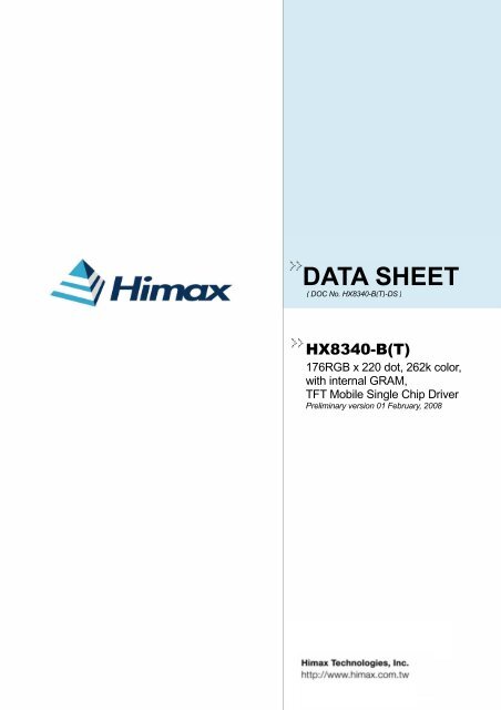
HX8340-B(T)176RGB x 220 dot, 262K color, TFT Mobile Single Chip Driver3. Block DiagramDATA SHEET Preliminary V01S1 ~ S528InternalregisterIM 3~0, IFSEL0EXTC7SourcedriverNCSNRD_ENWR_RNWDNC_SCLD17~0SDISDODEVSHSDOTCLKNRESETTEST3~1RLTBSHUTREVIDM183MPU IF18-bit16-bit9-bit8-bitSerial IFRGB IF18-bit16-bit6-bitOTPGRAM controlGRAMModeselectionVREG1D/A ConvertercircuitData LatchGrayscale voltagegeneratorV0~63VTESTVMONITimingControlGamma adjusting circuitVCIVDDDOSCPowerRegulatorGenerator TimingVGH/VGLGateDriverG1~G220VSSDVSSAStep Up1Step Up2Step Up3VCOM CricuitC11A/ C11BDDVDHC21A/ C21BC22A/ C22BV GHV GLC12A/ C12BV CLV COMHVCOMLV COM RV COMR C OSCHimax ConfidentialThis information contained herein is the exclusive property of Himax and shall not be distributed, reproduced, or disclosedin whole or in part without prior written permission of Himax.-P.11-February, 2008
HX8340-B(T)176RGB x 220 dot, 262K color, TFT Mobile Single Chip Driver4. Pin DescriptionDATA SHEET Preliminary V014.1 Pin DescriptionSignalsI/OPinNumberIM3, IM2, IM1, IM0 I 4NRESET I 1 MCUNCS I 1 MPUDNC I 1 MCUNRD(E) I 1 MCUNWR(RNW)(SCL) I 1 MCUSDI I 1 MCUSDO O 1 MCUDB[17:0] I/O 18 MCUVS I 1 MCUHS I 1 MCUDE I 1 MCUDOTCLK I 1 MCUTE O 1 MCUInterface Logic PinConnectedwithDescriptionSystem interface select.IM3 IM2 IM1 IM0Interface0 0 0 0 6800 MCU 16-bits Parallel0 0 0 1 6800 MCU 8-bits ParallelVSSD/0 0 1 0 8080 MCU 16-bits Parallel0 0 1 1 8080 MCU 8-bits ParallelIOVCC - 1 - ID Serial interface1 0 0 0 6800 MCU 18-bits Parallel1 0 0 1 6800 MCU 9-bits Parallel1 0 1 0 8080 MCU 18-bits Parallel1 0 1 1 8080 MCU 9-bits ParallelIf not used, please fix this pin to IOVCC or VSSD level.Reset pin. Setting either pin low initializes the LSI. Must bereset after power is supplied.Chip select input pin.Low: chip can be accessed;High: chip cannot be accessed.Command / parameter or display data selection pin in parallelbus system interface.If not used, please fix this pin at IOVCC or GND level.(NRD) Read enable pin I80 parallel bus system interface.(E) Read/Write operation enable pin in M68 parallel bussystem interface.If not used, please fix this pin at IOVCC or GND level(NWR) Write enable pin I80 parallel bus system interface.(RNW) Read/Write select pin in M68 parallel bus systeminterface.(SCL) server as serial data clock in serial bus system interface.If not used, please fix this pin at IOVCC or GND level.Serial data input pin in serial bus system interface. The data isinputted on the rising edge of the SCL signal.If not used, please fix this pin at IOVCC or GND level.Serial data output pin in serial bus system interface. The datais outputted on the falling edge of SCL signal. SDI and SDOpins are possible to connect together outside of driver IC asone SDA line.If not used, please let this pin floating.Input data busIf not used, please fix this pin at GND level.Vertical synchronizing signal in RGB interface. Has to be fixedto VSSD level if it is not used.Horizontal synchronizing signal in RGB interface. Has to befixed to VSSD level if it is not used.Data enable signal in RGB interface. Has to be fixed to VSSDlevel if it is not used.Pixel clock signal in RGB interface. Has to be fixed to VSSDlevel if is not used.Tearing effect output pin to synchronies MCU to frame writing,activated by S/W command.When this pin is not activated (TE function off), this pin is low.If not used, please let this pin open.Himax ConfidentialThis information contained herein is the exclusive property of Himax and shall not be distributed, reproduced, or disclosedin whole or in part without prior written permission of Himax.-P.12-February, 2008
HX8340-B(T)176RGB x 220 dot, 262K color, TFT Mobile Single Chip DriverDATA SHEET Preliminary V01Mode Select PinsPin ConnectedSignals I/ODescriptionNumber withInterface format select pinIFSELInterface Format Selection0 Register-content interface modeIFSEL I 1 MPU1 Command-Parameter interface modeIn this document, the IFSEL has to be connected to GND andRegister-Content interface mode is select.Extended command set access enable bit pinEXTC I 1 MPU In Register-content interface mode this pin is invalid.Internal pull low.RGB and System interface mode selection pin.RCM1, RCM0 MCU and RGB Interface Mode Select0x System Interface (1)10 RGB Interface (1) (VS+HS+DE)RCM1, RCM0 I 2 MCU11 RGB Interface (2) (VS+HS)As internal RCM[1:0] bits are written, the external pin RCM[1:0]control is invalid, and RGB and System interface modeselection is controlled by internal RCM[1:0] bits.If not used, please fix this pin to IOVCC or GND.SRGB I 1 MCUSMX I 1 MCUSMY I 1 MCUIDM I 1 MCUSHUT I 1 MCURGB direction select H/W pin for Color filter default setting.SRGB RGB Filter Order for Color Filter Default Setting0 S1, S2, S3 filter order =’B’, ‘G’, ‘R’1 S1, S2, S3 filter order =’R’, ‘G’, ‘B’As internal BGR bit ise written, the external pin SRGB controlis invalid, and RGB filter order is controlled by internal BGR bit.If not used, please fix this pin to IOVCC or GND.Module source output direction H/W select pin.SMXModule Source Output Direction0 S528 -> S11 S1 -> S528If not used, please fix this pin to IOVCC or GND.Module Gate output direction H/W select pin.SMYModule Gate Output Direction0 G1 -> G2201 G220 -> G1If not used, please fix this pin to IOVCC or GND.Normal mode and Idle mode control pin in RGB I/F.IDMIdle Mode H/W Controller0 Normal display (can be changed to Idle mode by S/W)1 Into Idle modeAs internal IDMON commands are written in RGB interface,the external pin IDM control is invalid, and normal and idlemode selection is controlled by internal IDMON commands.If not used, please fix this pin to IOVCC or GND.Chip On/ Off H/W control pin in RGB I/F.SHUNTDisplay On/Off in RGB I/F0 Display On1 Display OffAs internal CSHUT commands be written in RGB interface, theexternal pin SHUT control is invalid, and chip on/off selection iscontrolled by internal CSHUT commands.If not used, please fix this pin to IOVCC or GND.Himax ConfidentialThis information contained herein is the exclusive property of Himax and shall not be distributed, reproduced, or disclosedin whole or in part without prior written permission of Himax.-P.13-February, 2008
HX8340-B(T)176RGB x 220 dot, 262K color, TFT Mobile Single Chip DriverDATA SHEET Preliminary V01Mode Select PinsSignals I/OPin ConnectedNumber withDescriptionSource output direction H/W select pin in RGB I/F.RLModule Source Output Direction0 Normal DirectionRL I 1 MCU1 Reverse DirectionAs internal CRL bit be written in RGB interface, the external pinRL control is invalid, and CRL is operated based on externalpin SMX setting.If not used, please fix this pin to IOVCC or GND.Gate output direction H/W select pin in RGB I/F.TBModule Gate Output Direction0 Normal Direction1 Reverse DirectionTB I 1 MCUAs internal CTB bit be written in RGB interface, the external pinTB control is invalid, and CRL is operated based on externalpin SMY setting.If not used, please fix this pin to IOVCC or GND.Source output data polarity select H/W pin.REVSource Output Data Polarity0 Data not reverseREV I 1 MCU1 Data reverseAs internal INVON commands are written, the external pinREV control is invalid, and INVON commands are operatedbased on internal NB bit setting.If not used, please fix this pin to IOVCC or GND.Himax ConfidentialThis information contained herein is the exclusive property of Himax and shall not be distributed, reproduced, or disclosedin whole or in part without prior written permission of Himax.-P.14-February, 2008
HX8340-B(T)176RGB x 220 dot, 262K color, TFT Mobile Single Chip DriverDATA SHEET Preliminary V01Driver Output PinsSignals I/OPin ConnectedNumber withDescriptionS1~S528 O 528 LCD Source driver output pins.G1~G220 O 220 LCD Gate driver output pins.IOVCC P 1 Power Supply Digital IO Pad power supply. IOVCC = 1.65 ~ 3.3VVCI P 1 Power Supply Analog power supply. VCI = 2.5 ~ 3.3VVSSD P 1 Ground Digital groundVSSA P 1 Ground Analog groundPower supply pin used in OTP program mode and operatesVPP_OTP P 1 Power supply at 6.5V ± 0.2.C11A,C11B I/O 2C12A,C12B I/O 2C21A,C21BC22A,C22BI/O 4VDDD O 1VREG1 O 1VCOM O 1VCOMH O 1VCOML O 1VCOMR I 1VCL O 1DDVDH O 1VGH O 1VGL O 1Step-upCapacitorStep-upCapacitorStep-upCapacitorStabilizingCapacitorStabilizingCapacitorTFT commonelectrodeStabilizingcapacitorStabilizingcapacitorResistor oropenStabilizingcapacitorStabilizingcapacitorStabilizingcapacitorStabilizingcapacitorIf not in OTP program mode, please let it open.Connect to the step-up capacitors for step up circuit 1operation (DDVDH). Leave this pin open if the internalstep-up circuit is not used.Connect to the step-up capacitors for step up circuit 3operation (VCL). Leave this pin open if the internal step-upcircuit is not used.Connect to the step-up capacitors for step up circuit 2operations (VGH, VGL). Leave this pin open if the internalstep-up circuit is not used.Output from internal logic voltage (1.6V). Connect to astabilizing capacitorInternal generated stable power for source driver unit.The power supply of common voltage in TFT driving. Thevoltage amplitude between VCOMH and VCOML is output.Connect this pin to the common electrode in TFT panel.Connect this pin to the capacitor for stabilization. This pinindicates a high level of VCOM amplitude generated in drivingthe VCOM alternation.When the VCOM alternation is driven, this pin indicates a lowlevel of VCOM amplitude. Connect this pin to a capacitor forstabilization.A VCOMH reference voltage input. When adjusting VCOMHexternally, set registers to halt the VCOMH internal adjustingcircuit and connect a variable resistor between VREG1 andGND for VCOMH adjusting.A negative voltage of VCI x (-1) output for VCOML circuit.A power output from the step-up circuit1.Connect to a stabilizing capacitor between GND and DDVDH.DDVDH =5.1V (typ.) when VCI = 2.8V.A positive power output from the step-up circuit 2 for the gateline drive circuit.The step-up rate is determined by BT3-0 bits. Connect to astabilizing capacitor between GND and VGH.VGH=max 15.3VA negative power output from the step-up circuit 2 for the gateline drive circuit.The step-up rate is determined by BT(3-0) bits. Connect to astabilizing capacitor between GND and VGL.VGL=min -13.5VHimax ConfidentialThis information contained herein is the exclusive property of Himax and shall not be distributed, reproduced, or disclosedin whole or in part without prior written permission of Himax.-P.15-February, 2008
HX8340-B(T)176RGB x 220 dot, 262K color, TFT Mobile Single Chip DriverDATA SHEET Preliminary V01SignalsI/OPinNumberOSC I 1Test pin and othersConnectedwithExternalClock / OpenDescriptionExternal oscillator clock input with internal pull-low circuit. Thatinput is valid in test mode enable. Left it opens in normaloperation mode.TEST5-1 I 5 GND Test pin input (Internal pull low)REGVDD I 1 Open Test pin. Left it opens in normal operation mode.VMONI O 1 Open A test pin. Disconnect it.VTEST O 1 Open Gamma voltage of Panel test pin output. Must be left open.DUMMY1-44 - 32 OpenDummy pads, Dummy 18 and Dummy 19 are connection pinswhich can be contact resistance measurement pins.Himax ConfidentialThis information contained herein is the exclusive property of Himax and shall not be distributed, reproduced, or disclosedin whole or in part without prior written permission of Himax.-P.16-February, 2008
NO . 1NO. 215.DUMMY 1DUMMY 2VCOMVCOMVCOMVCOMDUMMY 3VGHVGHVGHVGHVGHDUMMY 4VGLVGLVGLVGLVGLDUMMY 5C22AC22AC22AC22BC22BC22BC22BC21AC21AC21AC21BC21BC21BVTESTVMONIVSSDVSSDVSSDVSSDVSSDVSSDVSSDVSSDVSSDVSSDDUMMY 6DUMMY 7DUMMY 8DUMMY 9DUMMY 10DUMMY 11C11AC11AC11AC11AC11AC11AC11AC11AC11BC11BC11BC11BC11BC11BC11BC11BVPP_OTPVPP_OTPVPP_OTPVPP_OTPVPP_OTPVPP_OTPDUMMY 12DUMMY 13DUMMY 14DUMMY 15DUMMY 16DUMMY 17C12AC12AC12AC12AC12AC12BC12BC12BC12BC12BDDVDHDDVDHDDVDHDDVDHDDVDHDDVDHDDVDHDDVDHVCIVCIVCIVCIVCIVCIVCIVCIVCIVCIVCLVCLVCLVCLVCLOSCDNCNCSVSHSDOTCLKDENRESETSDINRD_ENWR_RNW_SCLDB17DB16DB15DB14DB13DB12DB11DB10DB9DB8DB7DB6DB5DB4DB3DB2DB1DB0IM3IM2IM1IM0SDOREGVDDTEEXTCSRGBSMXSMYIFSELRCM0RCM1IDMSHUTRLREVVSSAVSSAVSSAVSSAVSSAVSSAVSSAVSSDVSSDVSSDVSSDVSSDVSSDVSSDVSSDVSSDVSSDVSSDVSSDVDDDVDDDVDDDVDDDVDDDVDDDVDDDVDDDVDDDVDDDVDDDVDDDIOVCCIOVCCIOVCCIOVCCIOVCCIOVCCTEST1TEST2VREG1VREG1VREG1VREG1VCOMHVCOMHVCOMLVCOMLVCOMRDUMMY18DUMMY19TEST3VCOMVCOMVCOMVCOMTEST4TEST5( A1)( A2)(B2)(B1)G 217G 219DUMMYDUMMYDUMMY 38DUMMYDUMMYDUMMY 35DUMMY 34DUMMY 33S 1S 2S262S263S264S265S266S267DUMMY44DUMMY43G1G3S 527S 528DUMMY 32DUMMYDUMMYDUMMY 29DUMMYDUMMYDUMMY 26DUMMY 25DUMMY 24G 220G 218G4G2DUMMY23DUMMY22DUMMY21DUMMY20NO . 606NO . 988NO . 600NO . 983NO . 328NO . 865NO . 221NO . 216HX8340-B(T)176RGB x 220 dot, 262K color, TFT Mobile Single Chip Driver4.2 Pin AssignmentDATA SHEET Preliminary V01Chip Size: 13880 um x 700 um(Including Seal-ring 20 um *2,Scribe line 40 um *2)Chip Thickness: 300 um (typ.)Pad Location: Pad centerCoordinate Origin: Chip centerAu Bump Size:1. 40 um x 56 umInput/Output(No. 1~ No. 215)2. 18 um x 100 umStaggered LCD output side(No. 216 ~ No. 988)DUMMY42DUMMY4140393736Face Up( Bump View )HX 8340-BPin AssignmentYX31302827Himax ConfidentialThis information contained herein is the exclusive property of Himax and shall not be distributed, reproduced, or disclosedin whole or in part without prior written permission of Himax.-P.17-February, 2008
HX8340-B(T)176RGB x 220 dot, 262K color, TFT Mobile Single Chip Driver4.3 Pad CoordinatesDATA SHEET Preliminary V01No. Pad name X Y No. Pad name X Y No. Pad name X Y No. Pad name X Y1 DUMMY1 -6695 -257 61 C11B -3095 -257 121 NWR/SCL 505 -257 181 VDDD 4655 -2572 DUMMY2 -6635 -257 62 C11B -3035 -257 122 DB17 565 -257 182 VDDD 4715 -2573 VCOM -6575 -257 63 C11B -2975 -257 123 DB16 650 -257 183 VDDD 4775 -2574 VCOM -6515 -257 64 C11B -2915 -257 124 DB15 735 -257 184 VDDD 4835 -2575 VCOM -6455 -257 65 C11B -2855 -257 125 DB14 820 -257 185 VDDD 4895 -2576 VCOM -6395 -257 66 VPP_OTP -2795 -257 126 DB13 905 -257 186 VDDD 4955 -2577 DUMMY3 -6335 -257 67 VPP_OTP -2735 -257 127 DB12 990 -257 187 VDDD 5015 -2578 VGH -6275 -257 68 VPP_OTP -2675 -257 128 DB11 1075 -257 188 VDDD 5075 -2579 VGH -6215 -257 69 VPP_OTP -2615 -257 129 DB10 1160 -257 189 VDDD 5135 -25710 VGH -6155 -257 70 VPP_OTP -2555 -257 130 DB9 1245 -257 190 IOVCC 5195 -25711 VGH -6095 -257 71 VPP_OTP -2495 -257 131 DB8 1330 -257 191 IOVCC 5255 -25712 VGH -6035 -257 72 DUMMY12 -2435 -257 132 DB7 1415 -257 192 IOVCC 5315 -25713 DUMMY4 -5975 -257 73 DUMMY13 -2375 -257 133 DB6 1500 -257 193 IOVCC 5375 -25714 VGL -5915 -257 74 DUMMY14 -2315 -257 134 DB5 1585 -257 194 IOVCC 5435 -25715 VGL -5855 -257 75 DUMMY15 -2255 -257 135 DB4 1670 -257 195 IOVCC 5495 -25716 VGL -5795 -257 76 DUMMY16 -2195 -257 136 DB3 1755 -257 196 TEST1 5555 -25717 VGL -5735 -257 77 DUMMY17 -2135 -257 137 DB2 1840 -257 197 TEST2 5615 -25718 VGL -5675 -257 78 C12A -2075 -257 138 DB1 1925 -257 198 VREG1 5675 -25719 DUMMY5 -5615 -257 79 C12A -2015 -257 139 DB0 2010 -257 199 VREG1 5735 -25720 C22A -5555 -257 80 C12A -1955 -257 140 IM3 2095 -257 200 VREG1 5795 -25721 C22A -5495 -257 81 C12A -1895 -257 141 IM2 2155 -257 201 VREG1 5855 -25722 C22A -5435 -257 82 C12A -1835 -257 142 IM1 2215 -257 202 VCOMH 5915 -25723 C22B -5375 -257 83 C12B -1775 -257 143 IM0 2275 -257 203 VCOMH 5975 -25724 C22B -5315 -257 84 C12B -1715 -257 144 SDO 2335 -257 204 VCOML 6035 -25725 C22B -5255 -257 85 C12B -1655 -257 145 REGVDD 2420 -257 205 VCOML 6095 -25726 C21A -5195 -257 86 C12B -1595 -257 146 TE 2505 -257 206 VCOMR 6155 -25727 C21A -5135 -257 87 C12B -1535 -257 147 EXTC 2590 -257 207 Dummy18 6215 -25728 C21A -5075 -257 88 DDVDH -1475 -257 148 SRGB 2675 -257 208 Dummy19 6275 -25729 C21B -5015 -257 89 DDVDH -1415 -257 149 SMX 2735 -257 209 TEST3 6335 -25730 C21B -4955 -257 90 DDVDH -1355 -257 150 SMY 2795 -257 210 VCOM 6395 -25731 C21B -4895 -257 91 DDVDH -1295 -257 151 IFSEL 2855 -257 211 VCOM 6455 -25732 VTEST -4835 -257 92 DDVDH -1235 -257 152 RCM0 2915 -257 212 VCOM 6515 -25733 VMONI -4775 -257 93 DDVDH -1175 -257 153 RCM1 2975 -257 213 VCOM 6575 -25734 VSSD -4715 -257 94 DDVDH -1115 -257 154 IDM 3035 -257 214 TEST4 6635 -25735 VSSD -4655 -257 95 DDVDH -1055 -257 155 SHUT 3095 -257 215 TEST5 6695 -25736 VSSD -4595 -257 96 VCI -995 -257 156 RL 3155 -257 216 Dummy20 6772 23637 VSSD -4535 -257 97 VCI -935 -257 157 TB 3215 -257 217 Dummy21 6756 11638 VSSD -4475 -257 98 VCI -875 -257 158 REV 3275 -257 218 Dummy22 6740 23639 VSSD -4415 -257 99 VCI -815 -257 159 VSSA 3335 -257 219 Dummy23 6724 11640 VSSD -4355 -257 100 VCI -755 -257 160 VSSA 3395 -257 220 G2 6708 23641 VSSD -4295 -257 101 VCI -695 -257 161 VSSA 3455 -257 221 G4 6692 11642 VSSD -4235 -257 102 VCI -635 -257 162 VSSA 3515 -257 222 G6 6676 23643 VSSD -4175 -257 103 VCI -575 -257 163 VSSA 3575 -257 223 G8 6660 11644 DUMMY6 -4115 -257 104 VCI -515 -257 164 VSSA 3635 -257 224 G10 6644 23645 DUMMY7 -4055 -257 105 VCI -455 -257 165 VSSA 3695 -257 225 G12 6628 11646 DUMMY8 -3995 -257 106 VCL -395 -257 166 VSSD 3755 -257 226 G14 6612 23647 DUMMY9 -3935 -257 107 VCL -335 -257 167 VSSD 3815 -257 227 G16 6596 11648 DUMMY10 -3875 -257 108 VCL -275 -257 168 VSSD 3875 -257 228 G18 6580 23649 DUMMY11 -3815 -257 109 VCL -215 -257 169 VSSD 3935 -257 229 G20 6564 11650 C11A -3755 -257 110 VCL -155 -257 170 VSSD 3995 -257 230 G22 6548 23651 C11A -3695 -257 111 OSC -95 -257 171 VSSD 4055 -257 231 G24 6532 11652 C11A -3635 -257 112 DNC -35 -257 172 VSSD 4115 -257 232 G26 6516 23653 C11A -3575 -257 113 NCS 25 -257 173 VSSD 4175 -257 233 G28 6500 11654 C11A -3515 -257 114 VS 85 -257 174 VSSD 4235 -257 234 G30 6484 23655 C11A -3455 -257 115 HS 145 -257 175 VSSD 4295 -257 235 G32 6468 11656 C11A -3395 -257 116 DOTCLK 205 -257 176 VSSD 4355 -257 236 G34 6452 23657 C11A -3335 -257 117 DE 265 -257 177 VSSD 4415 -257 237 G36 6436 11658 C11B -3275 -257 118 NRESET 325 -257 178 VDDD 4475 -257 238 G38 6420 23659 C11B -3215 -257 119 SDI 385 -257 179 VDDD 4535 -257 239 G40 6404 11660 C11B -3155 -257 120 NRD 445 -257 180 VDDD 4595 -257 240 G42 6388 236Himax ConfidentialThis information contained herein is the exclusive property of Himax and shall not be distributed, reproduced, or disclosedin whole or in part without prior written permission of Himax.-P.18-February, 2008
HX8340-B(T)176RGB x 220 dot, 262K color, TFT Mobile Single Chip DriverDATA SHEET Preliminary V01No. Pad name X Y No. Pad name X Y No. Pad name X Y No. Pad name X Y241 G44 6372 116 301 G164 5412 116 361 S506 4452 116 421 S446 3492 116242 G46 6356 236 302 G166 5396 236 362 S505 4436 236 422 S445 3476 236243 G48 6340 116 303 G168 5380 116 363 S504 4420 116 423 S444 3460 116244 G50 6324 236 304 G170 5364 236 364 S503 4404 236 424 S443 3444 236245 G52 6308 116 305 G172 5348 116 365 S502 4388 116 425 S442 3428 116246 G54 6292 236 306 G174 5332 236 366 S501 4372 236 426 S441 3412 236247 G56 6276 116 307 G176 5316 116 367 S500 4356 116 427 S440 3396 116248 G58 6260 236 308 G178 5300 236 368 S499 4340 236 428 S439 3380 236249 G60 6244 116 309 G180 5284 116 369 S498 4324 116 429 S438 3364 116250 G62 6228 236 310 G182 5268 236 370 S497 4308 236 430 S437 3348 236251 G64 6212 116 311 G184 5252 116 371 S496 4292 116 431 S436 3332 116252 G66 6196 236 312 G186 5236 236 372 S495 4276 236 432 S435 3316 236253 G68 6180 116 313 G188 5220 116 373 S494 4260 116 433 S434 3300 116254 G70 6164 236 314 G190 5204 236 374 S493 4244 236 434 S433 3284 236255 G72 6148 116 315 G192 5188 116 375 S492 4228 116 435 S432 3268 116256 G74 6132 236 316 G194 5172 236 376 S491 4212 236 436 S431 3252 236257 G76 6116 116 317 G196 5156 116 377 S490 4196 116 437 S430 3236 116258 G78 6100 236 318 G198 5140 236 378 S489 4180 236 438 S429 3220 236259 G80 6084 116 319 G200 5124 116 379 S488 4164 116 439 S428 3204 116260 G82 6068 236 320 G202 5108 236 380 S487 4148 236 440 S427 3188 236261 G84 6052 116 321 G204 5092 116 381 S486 4132 116 441 S426 3172 116262 G86 6036 236 322 G206 5076 236 382 S485 4116 236 442 S425 3156 236263 G88 6020 116 323 G208 5060 116 383 S484 4100 116 443 S424 3140 116264 G90 6004 236 324 G210 5044 236 384 S483 4084 236 444 S423 3124 236265 G92 5988 116 325 G212 5028 116 385 S482 4068 116 445 S422 3108 116266 G94 5972 236 326 G214 5012 236 386 S481 4052 236 446 S421 3092 236267 G96 5956 116 327 G216 4996 116 387 S480 4036 116 447 S420 3076 116268 G98 5940 236 328 G218 4980 236 388 S479 4020 236 448 S419 3060 236269 G100 5924 116 329 G220 4964 116 389 S478 4004 116 449 S418 3044 116270 G102 5908 236 330 Dummy24 4948 236 390 S477 3988 236 450 S417 3028 236271 G104 5892 116 331 Dummy25 4932 116 391 S476 3972 116 451 S416 3012 116272 G106 5876 236 332 Dummy26 4916 236 392 S475 3956 236 452 S415 2996 236273 G108 5860 116 333 Dummy27 4900 116 393 S474 3940 116 453 S414 2980 116274 G110 5844 236 334 Dummy28 4884 236 394 S473 3924 236 454 S413 2964 236275 G112 5828 116 335 Dummy29 4868 116 395 S472 3908 116 455 S412 2948 116276 G114 5812 236 336 Dummy30 4852 236 396 S471 3892 236 456 S411 2932 236277 G116 5796 116 337 Dummy31 4836 116 397 S470 3876 116 457 S410 2916 116278 G118 5780 236 338 Dummy32 4820 236 398 S469 3860 236 458 S409 2900 236279 G120 5764 116 339 S528 4804 116 399 S468 3844 116 459 S408 2884 116280 G122 5748 236 340 S527 4788 236 400 S467 3828 236 460 S407 2868 236281 G124 5732 116 341 S526 4772 116 401 S466 3812 116 461 S406 2852 116282 G126 5716 236 342 S525 4756 236 402 S465 3796 236 462 S405 2836 236283 G128 5700 116 343 S524 4740 116 403 S464 3780 116 463 S404 2820 116284 G130 5684 236 344 S523 4724 236 404 S463 3764 236 464 S403 2804 236285 G132 5668 116 345 S522 4708 116 405 S462 3748 116 465 S402 2788 116286 G134 5652 236 346 S521 4692 236 406 S461 3732 236 466 S401 2772 236287 G136 5636 116 347 S520 4676 116 407 S460 3716 116 467 S400 2756 116288 G138 5620 236 348 S519 4660 236 408 S459 3700 236 468 S399 2740 236289 G140 5604 116 349 S518 4644 116 409 S458 3684 116 469 S398 2724 116290 G142 5588 236 350 S517 4628 236 410 S457 3668 236 470 S397 2708 236291 G144 5572 116 351 S516 4612 116 411 S456 3652 116 471 S396 2642 116292 G146 5556 236 352 S515 4596 236 412 S455 3636 236 472 S395 2626 236293 G148 5540 116 353 S514 4580 116 413 S454 3620 116 473 S394 2610 116294 G150 5524 236 354 S513 4564 236 414 S453 3604 236 474 S393 2594 236295 G152 5508 116 355 S512 4548 116 415 S452 3588 116 475 S392 2578 116296 G154 5492 236 356 S511 4532 236 416 S451 3572 236 476 S391 2562 236297 G156 5476 116 357 S510 4516 116 417 S450 3556 116 477 S390 2546 116298 G158 5460 236 358 S509 4500 236 418 S449 3540 236 478 S389 2530 236299 G160 5444 116 359 S508 4484 116 419 S448 3524 116 479 S388 2514 116300 G162 5428 236 360 S507 4468 236 420 S447 3508 236 480 S387 2498 236Himax ConfidentialThis information contained herein is the exclusive property of Himax and shall not be distributed, reproduced, or disclosedin whole or in part without prior written permission of Himax.-P.19-February, 2008
HX8340-B(T)176RGB x 220 dot, 262K color, TFT Mobile Single Chip DriverDATA SHEET Preliminary V01No. Pad name X Y No. Pad name X Y No. Pad name X Y No. Pad name X Y481 S386 2482 116 541 S326 1522 116 601 S266 562 116 661 S206 -1482 116482 S385 2466 236 542 S325 1506 236 602 S265 546 236 662 S205 -1498 236483 S384 2450 116 543 S324 1490 116 603 S264 -554 116 663 S204 -1514 116484 S383 2434 236 544 S323 1474 236 604 S263 -570 236 664 S203 -1530 236485 S382 2418 116 545 S322 1458 116 605 S262 -586 116 665 S202 -1546 116486 S381 2402 236 546 S321 1442 236 606 S261 -602 236 666 S201 -1562 236487 S380 2386 116 547 S320 1426 116 607 S260 -618 116 667 S200 -1578 116488 S379 2370 236 548 S319 1410 236 608 S259 -634 236 668 S199 -1594 236489 S378 2354 116 549 S318 1394 116 609 S258 -650 116 669 S198 -1610 116490 S377 2338 236 550 S317 1378 236 610 S257 -666 236 670 S197 -1626 236491 S376 2322 116 551 S316 1362 116 611 S256 -682 116 671 S196 -1642 116492 S375 2306 236 552 S315 1346 236 612 S255 -698 236 672 S195 -1658 236493 S374 2290 116 553 S314 1330 116 613 S254 -714 116 673 S194 -1674 116494 S373 2274 236 554 S313 1314 236 614 S253 -730 236 674 S193 -1690 236495 S372 2258 116 555 S312 1298 116 615 S252 -746 116 675 S192 -1706 116496 S371 2242 236 556 S311 1282 236 616 S251 -762 236 676 S191 -1722 236497 S370 2226 116 557 S310 1266 116 617 S250 -778 116 677 S190 -1738 116498 S369 2210 236 558 S309 1250 236 618 S249 -794 236 678 S189 -1754 236499 S368 2194 116 559 S308 1234 116 619 S248 -810 116 679 S188 -1770 116500 S367 2178 236 560 S307 1218 236 620 S247 -826 236 680 S187 -1786 236501 S366 2162 116 561 S306 1202 116 621 S246 -842 116 681 S186 -1802 116502 S365 2146 236 562 S305 1186 236 622 S245 -858 236 682 S185 -1818 236503 S364 2130 116 563 S304 1170 116 623 S244 -874 116 683 S184 -1834 116504 S363 2114 236 564 S303 1154 236 624 S243 -890 236 684 S183 -1850 236505 S362 2098 116 565 S302 1138 116 625 S242 -906 116 685 S182 -1866 116506 S361 2082 236 566 S301 1122 236 626 S241 -922 236 686 S181 -1882 236507 S360 2066 116 567 S300 1106 116 627 S240 -938 116 687 S180 -1898 116508 S359 2050 236 568 S299 1090 236 628 S239 -954 236 688 S179 -1914 236509 S358 2034 116 569 S298 1074 116 629 S238 -970 116 689 S178 -1930 116510 S357 2018 236 570 S297 1058 236 630 S237 -986 236 690 S177 -1946 236511 S356 2002 116 571 S296 1042 116 631 S236 -1002 116 691 S176 -1962 116512 S355 1986 236 572 S295 1026 236 632 S235 -1018 236 692 S175 -1978 236513 S354 1970 116 573 S294 1010 116 633 S234 -1034 116 693 S174 -1994 116514 S353 1954 236 574 S293 994 236 634 S233 -1050 236 694 S173 -2010 236515 S352 1938 116 575 S292 978 116 635 S232 -1066 116 695 S172 -2026 116516 S351 1922 236 576 S291 962 236 636 S231 -1082 236 696 S171 -2042 236517 S350 1906 116 577 S290 946 116 637 S230 -1098 116 697 S170 -2058 116518 S349 1890 236 578 S289 930 236 638 S229 -1114 236 698 S169 -2074 236519 S348 1874 116 579 S288 914 116 639 S228 -1130 116 699 S168 -2090 116520 S347 1858 236 580 S287 898 236 640 S227 -1146 236 700 S167 -2106 236521 S346 1842 116 581 S286 882 116 641 S226 -1162 116 701 S166 -2122 116522 S345 1826 236 582 S285 866 236 642 S225 -1178 236 702 S165 -2138 236523 S344 1810 116 583 S284 850 116 643 S224 -1194 116 703 S164 -2154 116524 S343 1794 236 584 S283 834 236 644 S223 -1210 236 704 S163 -2170 236525 S342 1778 116 585 S282 818 116 645 S222 -1226 116 705 S162 -2186 116526 S341 1762 236 586 S281 802 236 646 S221 -1242 236 706 S161 -2202 236527 S340 1746 116 587 S280 786 116 647 S220 -1258 116 707 S160 -2218 116528 S339 1730 236 588 S279 770 236 648 S219 -1274 236 708 S159 -2234 236529 S338 1714 116 589 S278 754 116 649 S218 -1290 116 709 S158 -2250 116530 S337 1698 236 590 S277 738 236 650 S217 -1306 236 710 S157 -2266 236531 S336 1682 116 591 S276 722 116 651 S216 -1322 116 711 S156 -2282 116532 S335 1666 236 592 S275 706 236 652 S215 -1338 236 712 S155 -2298 236533 S334 1650 116 593 S274 690 116 653 S214 -1354 116 713 S154 -2314 116534 S333 1634 236 594 S273 674 236 654 S213 -1370 236 714 S153 -2330 236535 S332 1618 116 595 S272 658 116 655 S212 -1386 116 715 S152 -2346 116536 S331 1602 236 596 S271 642 236 656 S211 -1402 236 716 S151 -2362 236537 S330 1586 116 597 S270 626 116 657 S210 -1418 116 717 S150 -2378 116538 S329 1570 236 598 S269 610 236 658 S209 -1434 236 718 S149 -2394 236539 S328 1554 116 599 S268 594 116 659 S208 -1450 116 719 S148 -2410 116540 S327 1538 236 600 S267 578 236 660 S207 -1466 236 720 S147 -2426 236Himax ConfidentialThis information contained herein is the exclusive property of Himax and shall not be distributed, reproduced, or disclosedin whole or in part without prior written permission of Himax.-P.20-February, 2008
HX8340-B(T)176RGB x 220 dot, 262K color, TFT Mobile Single Chip DriverDATA SHEET Preliminary V01No. Pad name X Y No. Pad name X Y No. Pad name X Y No. Pad name X Y721 S146 -2442 116 781 S86 -3452 116 841 S26 -4412 116 901 G167 -5372 116722 S145 -2458 236 782 S85 -3468 236 842 S25 -4428 236 902 G165 -5388 236723 S144 -2474 116 783 S84 -3484 116 843 S24 -4444 116 903 G163 -5404 116724 S143 -2490 236 784 S83 -3500 236 844 S23 -4460 236 904 G161 -5420 236725 S142 -2506 116 785 S82 -3516 116 845 S22 -4476 116 905 G159 -5436 116726 S141 -2522 236 786 S81 -3532 236 846 S21 -4492 236 906 G157 -5452 236727 S140 -2538 116 787 S80 -3548 116 847 S20 -4508 116 907 G155 -5468 116728 S139 -2554 236 788 S79 -3564 236 848 S19 -4524 236 908 G153 -5484 236729 S138 -2570 116 789 S78 -3580 116 849 S18 -4540 116 909 G151 -5500 116730 S137 -2586 236 790 S77 -3596 236 850 S17 -4556 236 910 G149 -5516 236731 S136 -2602 116 791 S76 -3612 116 851 S16 -4572 116 911 G147 -5532 116732 S135 -2618 236 792 S75 -3628 236 852 S15 -4588 236 912 G145 -5548 236733 S134 -2634 116 793 S74 -3644 116 853 S14 -4604 116 913 G143 -5564 116734 S133 -2650 236 794 S73 -3660 236 854 S13 -4620 236 914 G141 -5580 236735 S132 -2716 116 795 S72 -3676 116 855 S12 -4636 116 915 G139 -5596 116736 S116 -2732 236 796 S71 -3692 236 856 S11 -4652 236 916 G137 -5612 236737 S130 -2748 116 797 S70 -3708 116 857 S10 -4668 116 917 G135 -5628 116738 S129 -2764 236 798 S69 -3724 236 858 S9 -4684 236 918 G133 -5644 236739 S128 -2780 116 799 S68 -3740 116 859 S8 -4700 116 919 G116 -5660 116740 S127 -2796 236 800 S67 -3756 236 860 S7 -4716 236 920 G129 -5676 236741 S126 -2812 116 801 S66 -3772 116 861 S6 -4732 116 921 G127 -5692 116742 S125 -2828 236 802 S65 -3788 236 862 S5 -4748 236 922 G125 -5708 236743 S124 -2844 116 803 S64 -3804 116 863 S4 -4764 116 923 G123 -5724 116744 S123 -2860 236 804 S63 -3820 236 864 S3 -4780 236 924 G121 -5740 236745 S122 -2876 116 805 S62 -3836 116 865 S2 -4796 116 925 G119 -5756 116746 S121 -2892 236 806 S61 -3852 236 866 S1 -4812 236 926 G117 -5772 236747 S120 -2908 116 807 S60 -3868 116 867 Dummy33 -4828 116 927 G115 -5788 116748 S119 -2924 236 808 S59 -3884 236 868 Dummy34 -4844 236 928 G113 -5804 236749 S118 -2940 116 809 S58 -3900 116 869 Dummy35 -4860 116 929 G111 -5820 116750 S117 -2956 236 810 S57 -3916 236 870 Dummy36 -4876 236 930 G109 -5836 236751 S116 -2972 116 811 S56 -3932 116 871 Dummy37 -4892 116 931 G107 -5852 116752 S115 -2988 236 812 S55 -3948 236 872 Dummy38 -4908 236 932 G105 -5868 236753 S114 -3004 116 813 S54 -3964 116 873 Dummy39 -4924 116 933 G103 -5884 116754 S113 -3020 236 814 S53 -3980 236 874 Dummy40 -4940 236 934 G101 -5900 236755 S112 -3036 116 815 S52 -3996 116 875 G219 -4956 116 935 G99 -5916 116756 S111 -3052 236 816 S51 -4012 236 876 G217 -4972 236 936 G97 -5932 236757 S110 -3068 116 817 S50 -4028 116 877 G215 -4988 116 937 G95 -5948 116758 S109 -3084 236 818 S49 -4044 236 878 G213 -5004 236 938 G93 -5964 236759 S108 -3100 116 819 S48 -4060 116 879 G211 -5020 116 939 G91 -5980 116760 S107 -3116 236 820 S47 -4076 236 880 G209 -5036 236 940 G89 -5996 236761 S106 -3132 116 821 S46 -4092 116 881 G207 -5052 116 941 G87 -6012 116762 S105 -3148 236 822 S45 -4108 236 882 G205 -5068 236 942 G85 -6028 236763 S104 -3164 116 823 S44 -4124 116 883 G203 -5084 116 943 G83 -6044 116764 S103 -3180 236 824 S43 -4140 236 884 G201 -5100 236 944 G81 -6060 236765 S102 -3196 116 825 S42 -4156 116 885 G199 -5116 116 945 G79 -6076 116766 S101 -3212 236 826 S41 -4172 236 886 G197 -5132 236 946 G77 -6092 236767 S100 -3228 116 827 S40 -4188 116 887 G195 -5148 116 947 G75 -6108 116768 S99 -3244 236 828 S39 -4204 236 888 G193 -5164 236 948 G73 -6124 236769 S98 -3260 116 829 S38 -4220 116 889 G191 -5180 116 949 G71 -6140 116770 S97 -3276 236 830 S37 -4236 236 890 G189 -5196 236 950 G69 -6156 236771 S96 -3292 116 831 S36 -4252 116 891 G187 -5212 116 951 G67 -6172 116772 S95 -3308 236 832 S35 -4268 236 892 G185 -5228 236 952 G65 -6188 236773 S94 -3324 116 833 S34 -4284 116 893 G183 -5244 116 953 G63 -6204 116774 S93 -3340 236 834 S33 -4300 236 894 G181 -5260 236 954 G61 -6220 236775 S92 -3356 116 835 S32 -4316 116 895 G179 -5276 116 955 G59 -6236 116776 S91 -3372 236 836 S31 -4332 236 896 G177 -5292 236 956 G57 -6252 236777 S90 -3388 116 837 S30 -4348 116 897 G175 -5308 116 957 G55 -6268 116778 S89 -3404 236 838 S29 -4364 236 898 G173 -5324 236 958 G53 -6284 236779 S88 -3420 116 839 S28 -4380 116 899 G171 -5340 116 959 G51 -6300 116780 S87 -3436 236 840 S27 -4396 236 900 G169 -5356 236 960 G49 -6316 236Himax ConfidentialThis information contained herein is the exclusive property of Himax and shall not be distributed, reproduced, or disclosedin whole or in part without prior written permission of Himax.-P.21-February, 2008
HX8340-B(T)176RGB x 220 dot, 262K color, TFT Mobile Single Chip DriverDATA SHEET Preliminary V01No. Pad name X Y961 G47 -6332 116962 G45 -6348 236963 G43 -6364 116964 G41 -6380 236965 G39 -6396 116966 G37 -6412 236967 G35 -6428 116968 G33 -6444 236969 G31 -6460 116970 G29 -6476 236971 G27 -6492 116972 G25 -6508 236973 G23 -6524 116974 G21 -6540 236975 G19 -6556 116976 G17 -6572 236977 G15 -6588 116978 G13 -6604 236979 G11 -6620 116980 G9 -6636 236981 G7 -6652 116982 G5 -6668 236983 G3 -6684 116984 G1 -6700 236985 Dummy41 -6716 116986 Dummy42 -6732 236987 Dummy43 -6748 116988 Dummy44 -6764 236Alignment Mark X YA1 -6827.5 -219.5A2 +6827.5 -219.5B1 -6852.5 274B2 6852.5 274Himax ConfidentialThis information contained herein is the exclusive property of Himax and shall not be distributed, reproduced, or disclosedin whole or in part without prior written permission of Himax.-P.22-February, 2008
HX8340-B(T)176RGB x 220 dot, 262K color, TFT Mobile Single Chip Driver4.4 Alignment MarkDATA SHEET Preliminary V01A_MARK (A1)A_MARK (A2)A_MARK (B1)A_MARK (B2)6.5um25um25um15 um15um 25um25um15umHimax ConfidentialThis information contained herein is the exclusive property of Himax and shall not be distributed, reproduced, or disclosedin whole or in part without prior written permission of Himax.-P.23-February, 2008
HX8340-B(T)176RGB x 220 dot, 262K color, TFT Mobile Single Chip Driver4.5 Bump SizeDATA SHEET Preliminary V01Input PADOutput PAD18um20um18X10032umHimax ConfidentialThis information contained herein is the exclusive property of Himax and shall not be distributed, reproduced, or disclosedin whole or in part without prior written permission of Himax.-P.24-February, 2008
HX8340-B(T)176RGB x 220 dot, 262K color, TFT Mobile Single Chip Driver5. InterfaceDATA SHEET Preliminary V01The HX8340-B supports two-type interface group: Command-Parameter interface mode,Register-Content interface mode.This manual description focuses on Register-Content interface mode. About theCommand-Parameter interface mode, please refer to the HX8340-B (N) <strong>datasheet</strong> for detail.In Register-Content interface mode (IFSEL0=‘L’), the HX8340-B has a system interface circuitfor command/parameter (include display data) transferring, and a RGB interface circuit fordata transferring during animated display. The system interface circuit uses data bus pins(DB17-0). Since the data bus pins (DB17-0) can be used as input in RGB interface circuit, theHX8340-B shows animated display with less wiring.System interface can be used to access internal command and internal 18-bit/pixel GRAM. TheRGB interface is only used to access display data. Please make sure that in RGB interfacemode, the input display data is not written to GRAM and is displayed directly.Himax ConfidentialThis information contained herein is the exclusive property of Himax and shall not be distributed, reproduced, or disclosedin whole or in part without prior written permission of Himax.-P.25-February, 2008
HX8340-B(T)176RGB x 220 dot, 262K color, TFT Mobile Single Chip Driver5.1 System Interface CircuitDATA SHEET Preliminary V01The register-content interface circuit in HX8340-B supports 18-/16-/9-/8-bit bus width parallelbus system interface for I80 series and M68 series CPU, and a serial bus system interface forserial data input. When NCS = ‘L’, the parallel and serial bus system interface of the HX8340-Bbecome active and data transfer through the interface circuit is available. The input bus widthformat of system interface circuit is selected by external pins IM3-0 setting. For selecting theinput bus format, please refer to Table 5.1.In register-content interface, it includes command code and the following parameter and GRAMdata. The command code can be written through data bus by setting DNC =’0’. Then theparameter or GRAM data can be written to register at which that index pointer pointed by settingDNC=’1’.IM3 IM2 IM1 IM0InterfaceNRD_ENWR_RNW_SCLDNCData Bus use0 0 0 0 6800 MCU 16-bits Parallel E RNW DNC DB0, DB9: Unused, DB17-B10, DB8-DB1: 16-bit data0 0 0 1 6800 MCU 8-bits Parallel E RNW DNC DB9- DB0 Unused, DB17-DB10: 8-bits Data0 0 1 0 8080 MCU 16-bits Parallel NRD_E NWR DNC DB0, DB9: Unused, DB17-10, DB8-DB1: 16-bit data0 0 1 1 8080 MCU 8-bits Parallel NRD_E NWR DNC DB9- DB0: Unused, DB17-DB10: 8-bits Data- 1 - ID Serial interface Note (1) SCL Note (1) SDI, SDO1 0 0 0 6800 MCU 18-bits Parallel E RNW DNC DB17-DB0: 18-bits Data1 0 0 1 6800 MCU 9-bits Parallel E RNW DNC DB8-DB0: Unused, DB17-DB9: 9-bits Data1 0 1 0 8080 MCU 18-bits Parallel NRD_E NWR DNC DB17-DB0: 18-bits Data1 0 1 1 8080 MCU 9-bits Parallel NRD_E NWR DNC DB8-DB0: Unused, DB17-DB9: 9-bits DataOther Setting Setting InvalidNote: (1) Can be connected to GND or IOVCC level.(2) SDI and SDO can be tie together as SDATable 5. 1 Pin connection According to MCU Interface Type SelectionHimax ConfidentialThis information contained herein is the exclusive property of Himax and shall not be distributed, reproduced, or disclosedin whole or in part without prior written permission of Himax.-P.26-February, 2008
HX8340-B(T)176RGB x 220 dot, 262K color, TFT Mobile Single Chip Driver5.1.1 Parallel Bus System InterfaceDATA SHEET Preliminary V01The input / output data from data pins (DB17-0) and signal operation of the I80/M68 seriesparallel bus interface are listed in Table 5.2 and Table 5.3.IM3 IM2 IM1 IM0 Interface0 0 1 00 0 1 11 0 1 01 0 1 116-bitsParallel8-bitsParallel18-bitsParallel9-bitsParallelIM3 IM2 IM1 IM0 Interface0 0 0 00 0 0 11 0 0 01 0 0 116-bitsParallel8-bitsParallel18-bitsParallel9-bitsParallelDNCNRD_ENWR_RNW_SCLFunction0 1 ↑ Write 8-bits command (DB8 to DB1)1 1 ↑ Write 8-bits parameter (DB8 to DB1)1 1 ↑ Write 16-bits display data (DB17 to DB10, DB8 to DB1)1 ↑ 1 Read 8-bits command (DB8 to DB1)1 ↑ 1 Read 16-bits display data (DB17 to DB10, DB8 to DB1)0 1 ↑ Write 8-bits command (DB17 to DB10)1 1 ↑ Write 8-bits parameter (DB17 to DB10)1 1 ↑ Write 8-bits display data (DB17 to DB10)1 ↑ 1 Read 8-bits parameter or status (DB17 to DB10)1 ↑ 1 Read 8-bits display data (DB17 to DB10)0 1 ↑ Write 8-bits command (DB8 to DB1)1 1 ↑ Write 8-bits parameter (DB8 to DB1)1 1 ↑ Write 18-bits display data (DB17 to DB0)1 ↑ 1 Read 8-bits parameter or status (DB8 to DB1)1 ↑ 1 Read 18-bits display data (DB17 to DB0)0 1 ↑ Write 8-bits command (DB17 to DB10)1 1 ↑ Write 8-bits parameter (DB17 to DB10)1 1 ↑ Write 9-bits display data (DB17 to DB9)1 ↑ 1 Read 8-bits command (DB17 to DB10)1 ↑ 1 Read 9-bits display data (DB17 to DB9)Table 5. 2 Data Pin Function for I80 Series CPUDNCNWR_RNW_SCLNRD_EFunction0 0 ↓ Write 8-bits command (DB8 to DB1)1 0 ↓ Write 8-bits parameter (DB8 to DB1)1 0 ↓ Write 16-bits display data (DB17 to DB10, DB8 to DB1)1 1 ↓ Read 8-bits command (DB8 to DB1)1 1 ↓ Read 16-bits display data (DB17 to DB10, DB8 to DB1)0 0 ↓ Write 8-bits command (DB17 to DB10)1 0 ↓ Write 8-bits parameter (DB17 to DB10)1 0 ↓ Write 8-bits display data (DB17 to DB10)1 1 ↓ Read 8-bits parameter or status (DB17 to DB10)1 1 ↓ Read 8-bits display data (DB17 to DB10)0 0 ↓ Write 8-bits command (DB8 to DB1)1 0 ↓ Write 8-bits parameter (DB8 to DB1)1 0 ↓ Write 18-bits display data (DB17 to DB0)1 1 ↓ Read 8-bits parameter or status (DB8 to DB1)1 1 ↓ Read 18-bits display data (DB17 to DB0)0 0 ↓ Write 8-bits command (DB17 to DB10)1 0 ↓ Write 8-bits parameter (DB17 to DB10)1 0 ↓ Write 9-bits display data (DB17 to DB9)1 1 ↓ Read 8-bits command (DB17 to DB10)1 1 ↓ Read 9-bits display data (DB17 to DB9)Table 5. 3 Data Pin Function for M68 Series CPUHimax ConfidentialThis information contained herein is the exclusive property of Himax and shall not be distributed, reproduced, or disclosedin whole or in part without prior written permission of Himax.-P.27-February, 2008
HX8340-B(T)176RGB x 220 dot, 262K color, TFT Mobile Single Chip DriverDATA SHEET Preliminary V01Write to the registerNCSDNCNRD_ENWR_RNWDB[B:0]"index" write to index registerCommand write to the registerRead the registerNCSDNCNRD_ENWR_RNWDB[B:0]"index" write to index registerDummy ReadCommand read from the registerFigure 5. 1 Register Read/Write Timing in Parallel Bus System Interface (for I80 Series MPU)Write to the graphic RAMNCSDNCNRD_ENWR_ RNWDB[B:0]"22" h 1st write data 2nd write data 3rd write data 4th write data5th write dataRead the graphic RAMNCSDNCNRD_ENWR_RNWDB[B:0]"22" h1st read data 2nd read read 3rd read dataRGB R GDummy Read DataFigure 5. 2 GRAM Read/Write Timing in Bit Parallel Bus System Interface (for I80 Series MPU)Himax ConfidentialThis information contained herein is the exclusive property of Himax and shall not be distributed, reproduced, or disclosedin whole or in part without prior written permission of Himax.-P.28-February, 2008
HX8340-B(T)176RGB x 220 dot, 262K color, TFT Mobile Single Chip DriverDATA SHEET Preliminary V01Figure 5. 3 Register Read/Write Timing in Parallel Bus System Interface (for M68 Series MPU)Figure 5. 4 GRAM Read/Write Timing in Bit Parallel Bus System Interface (for M68 Series MPU)Himax ConfidentialThis information contained herein is the exclusive property of Himax and shall not be distributed, reproduced, or disclosedin whole or in part without prior written permission of Himax.-P.29-February, 2008
HX8340-B(T)176RGB x 220 dot, 262K color, TFT Mobile Single Chip Driver5.1.2 MCU Data Color CodingDATA SHEET Preliminary V01MCU Data Color Coding for RAM data Write- Parallel 8-Bits Bus InterfaceRegister DB17 DB16 DB15 DB14 DB13 DB12 DB11 DB10 DB9 DB8 DB7 DB6 DB5 DB4 DB3 DB2 DB1 DB0 CommandCommand 0 0 1 0 0 0 1 0 x x x x x x x x x x 22H17H DB17 DB16 DB15 DB14 DB13 DB12 DB11 DB10 DB9 DB8 DB7 DB6 DB5 DB4 DB3 DB2 DB1 DB0 Color03h05h06hR3 R2 R1 R0 G3 G2 G1 G0 x x x x x x x x x xB3 B2 B1 B0 R3 R2 R1 R0 x x x x x x x x x xG3 G2 G1 G0 B3 B2 B1 B0 x x x x x x x x x xR4 R3 R2 R1 R0 G5 G4 G3 x x x x x x x x x xG2 G1 G0 B4 B3 B2 B1 B0 x x x x x x x x x xR5 R4 R3 R2 R1 R0 x x x x x x x x x x x xG5 G4 G3 G2 G1 G0 x x x x x x x x x x x xB5 B4 B3 B2 B1 B0 x x x x x x x x x x x xTable 5. 4 8-Bits Parallel Interface Set Table- Parallel 16-Bits Bus Interface4K-Color(2-pixels/ 3-byyes)65K-Color(1-pixels/ 2-byyes)262K-Color(1-pixels/ 3byyes)Register DB17 DB16 DB15 DB14 DB13 DB12 DB11 DB10 DB9 DB8 DB7 DB6 DB5 DB4 DB3 DB2 DB1 DB0 CommandCommand x 0 0 1 0 0 0 1 0 x 22H17H DB17 DB16 DB15 DB14 DB13 DB12 DB11 DB10 DB9 DB8 DB7 DB6 DB5 DB4 DB3 DB2 DB1 DB0 Color03h x x x x R3 R2 R1 R0 x G3 G2 G1 G0 B3 B2 B1 B0 x 4K-Color05h R4 R3 R2 R1 R0 G5 G4 G3 x G2 G1 G0 B4 B3 B2 B1 B0 x 65K-Color06hR5 R4 R3 R2 R1 R0 x x x G5 G4 G3 G2 G1 G0 x x xB5 B4 B3 B2 B1 B0 x x x R5 R4 R3 R2 R1 R0 x x xG5 G4 G3 G2 G1 G0 x x x B5 B4 B3 B2 B1 B0 x x xTable 5. 5 16-Bits Parallel Interface Set Table- Parallel 9-Bits Bus Interface262K-Color(2-pixels/ 3byyes)Register DB17 DB16 DB15 DB14 DB13 DB12 DB11 DB10 DB9 DB8 DB7 DB6 DB5 DB4 DB3 DB2 DB1 DB0 RegisterCommand 0 0 1 0 0 0 1 0 x x x x x x x x x x 22H17H DB17 DB16 DB15 DB14 DB13 DB12 DB11 DB10 DB9 DB8 DB7 DB6 DB5 DB4 DB3 DB2 DB1 DB0 ColorR5 R4 R3 R2 R1 R0 G5 G4 G3 x x x x x x x x x 262K-Color06hG2 G1 G0 B5 B4 B3 B2 B1 B0 x x x x x x x x x (1-pixels/ 2bytes)- Parallel 18-Bits Bus InterfaceRegisterTable 5. 6 9-Bits Parallel Interface Set TableDB17 DB16 DB15 DB14 DB13 DB12 DB11 DB10 DB9 DB8 DB7 DB6 DB5 DB4 DB3 DB2 DB1 DB0 RegisterCommand x x x x x x x x x 0 0 1 0 0 0 1 0 x 22H17H DB17 DB16 DB15 DB14 DB13 DB12 DB11 DB10 DB9 DB8 DB7 DB6 DB5 DB4 DB3 DB2 DB1 DB0 Color03h x x x x x x R3 R2 R1 R0 G3 G2 G1 G0 B3 B2 B1 B0 4K-Color05h x x R4 R3 R2 R1 R0 G5 G4 G3 G2 G1 G0 B4 B3 B2 B1 B0 65K-Color06h R5 R4 R3 R2 R1 R0 G5 G4 G3 G2 G1 G0 B5 B4 B3 B2 B1 B0 262K-ColorTable 5. 7 18-Bits Parallel Interface Set TableHimax ConfidentialThis information contained herein is the exclusive property of Himax and shall not be distributed, reproduced, or disclosedin whole or in part without prior written permission of Himax.-P.30-February, 2008
HX8340-B(T)176RGB x 220 dot, 262K color, TFT Mobile Single Chip DriverParallel 8-Bits Bus Interface for RAM Data WriteDATA SHEET Preliminary V01Different display data formats are available for three colors depth supported by listed below.- 4K-Colors, RGB 4, 4, 4-bits input data. (17H=”03h”)- 65K-Colors, RGB 5, 6, 5-bits input data. (17H=”05h”)- 262K-Colors, RGB 6, 6, 6-bits input data. (17H=”06h”)Figure 5. 5 Example of I80- / M68- System 8-Bit Parallel Bus InterfaceHimax ConfidentialThis information contained herein is the exclusive property of Himax and shall not be distributed, reproduced, or disclosedin whole or in part without prior written permission of Himax.-P.31-February, 2008
HX8340-B(T)176RGB x 220 dot, 262K color, TFT Mobile Single Chip DriverDATA SHEET Preliminary V018-bits data bus for 12-bits/pixel (RGB 4-4-4-bits input), 4K-colors, 17H=”03h”There are 2-pixels (6 sub-pixels) per 3-bytes.NRESET ‘1’NCSDNCNWRNRDRNW‘1’‘0’8080-Series control pins6800-Series control pinsEDB17 R1, Bit 3 B1, Bit 3 G2, Bit 3 R3, Bit 30DB16 R1, Bit 2 B1, Bit 2 G2, Bit 2 R3, Bit 20DB15 R1, Bit 1 B1, Bit 1 G2, Bit 1 R3, Bit 11DB14 R1, Bit 0 B1, Bit 0 G2, Bit 0 R3, Bit 00DB13 G1, Bit 3 R2, Bit 3 B2, Bit 3 G3, Bit 30DB12 G1, Bit 2 R2, Bit 2 B2, Bit 2 G3, Bit 20DB11 G1, Bit 1 R2, Bit 1 B2, Bit 1 G3, Bit 11DB10 G1, Bit 0 R2, Bit 0 B2, Bit 0 G3, Bit 00Pixel n Pixel n+112-bits12-bitsLook-Up Table for 4K-colors or data mapping (12-Bits to 18-Bits)FrameMemory18-bits18-bitsR1 G1 B1 R2 G2 B2 R3 G3 B3Note: (1) The data order is ad follows, MSB=D7, LSB=D0 and picture data is MSB=Bit 3, LSB=Bit 0 for Red, Green andBlue data.(2) 3-times transfer is used to transmit 1 pixel data with the 12-bits color depth information.(3) ‘-‘ = Don't care - Can be set to IOVCC or VSSD level.Figure 5. 6 8-bit data bus for 12-bits/pixelHimax ConfidentialThis information contained herein is the exclusive property of Himax and shall not be distributed, reproduced, or disclosedin whole or in part without prior written permission of Himax.-P.32-February, 2008
HX8340-B(T)176RGB x 220 dot, 262K color, TFT Mobile Single Chip DriverDATA SHEET Preliminary V018-bits data bus for 16-bits/pixel (RGB 5-6-5-bits input), 65K-colors, 17H=”05h”There is 1-pixel (3 sub-pixels) per 2-bytes.NRESET ‘1’NCSDNCNWRNRDRNW‘1’‘0’8080-Series control pins6800-Series control pinsEDB17 R1, Bit 4 G1, Bit 2 R2, Bit 4 G2, Bit 20DB16 R1, Bit 3 G1, Bit 1 R2, Bit 3 G2, Bit 10DB15 R1, Bit 2 G1, Bit 0 R2, Bit 2 G2, Bit 01DB14 R1, Bit 1 B1, Bit 5 R2, Bit 1 B2, Bit 50DB13 R1, Bit 0 B1, Bit 3 R2, Bit 0 B2, Bit 30DB12 G1, Bit 5 B1, Bit 2 G2, Bit 5 B2, Bit 20DB11 G1, Bit 4 B1, Bit 1 G2, Bit 4 B2, Bit 11DB10 G1, Bit 3 B1, Bit 0 G2, Bit 3 B2, Bit 00Pixel n Pixel n+116-bits16-bitsLook-Up Table for 4K-colors or data mapping (16-Bits to 18-Bits)FrameMemory18-bits18-bitsR1 G1 B1 R2 G2 B2 R3 G3 B3Note: (1) The data order is ad follows, MSB=D7, LSB=D0 and picture data is MSB=Bit 5, LSB=Bit 0 for Green andMSB=Bit 4, LSB=Bit 0 for Red and Blue data.(2) 2-times transfer is used to transmit 1 pixel data with the 16-bits color depth information.(3) ‘-‘ = Don't care - Can be set to IOVCC or VSSD level.Figure 5. 7 8-bit data bus for 16-bits/pixelHimax ConfidentialThis information contained herein is the exclusive property of Himax and shall not be distributed, reproduced, or disclosedin whole or in part without prior written permission of Himax.-P.33-February, 2008
HX8340-B(T)176RGB x 220 dot, 262K color, TFT Mobile Single Chip Driver8-bits data bus for 18-bits/pixel (RGB 6-6-6-bits input), 262K-colors, 17H=”06h”There is 1-pixel (3 sub-pixels) per 3-bytes.DATA SHEET Preliminary V01NRESET ‘1’NCSDNCNWRNRDRNW‘1’‘0’8080-Series control pins6800-Series control pinsEDB17 R1, Bit 5 G1, Bit 5 B1, Bit 5 R2, Bit 50DB16 R1, Bit 4 G1, Bit 4 B1, Bit 4 R2, Bit 40DB15 R1, Bit 3 G1, Bit 3 B1, Bit 3 R2, Bit 31DB14 R1, Bit 2 G1, Bit 2 B1, Bit 2 R2, Bit 20DB13 R1, Bit 1 G1, Bit 1 B1, Bit 1 R2, Bit 10DB12 R1, Bit 0 G1, Bit 0 B1, Bit 0 R2, Bit 00DB11 - - - -1DB10 - - - -0Pixel n Pixel n+1FrameMemory18-bits18-bitsR1 G1 B1 R2 G2 B2 R3 G3 B3Note: (1) The data order is ad follows, MSB=D7, LSB=D0 and picture data is MSB=Bit 5, LSB=Bit 0 for Red, Green andBlue data.(2) 3-times transfer is used to transmit 1 pixel data with the 18-bits color depth information.(3) ‘-‘ = Don't care - Can be set to IOVCC or VSSD level.Figure 5. 8 8-bit data bus for 18-bits/pixelHimax ConfidentialThis information contained herein is the exclusive property of Himax and shall not be distributed, reproduced, or disclosedin whole or in part without prior written permission of Himax.-P.34-February, 2008
HX8340-B(T)176RGB x 220 dot, 262K color, TFT Mobile Single Chip DriverParallel 16-Bits Bus Interface for RAM Data WriteDATA SHEET Preliminary V01Different display data formats are available for three colors depth supported by listed below.- 4K-Colors, RGB 4, 4, 4-bits input data. (17H=”03h”)- 65K-Colors, RGB 5, 6, 5-bits input data. (17H=”05h”)- 262K-Colors, RGB 6, 6, 6-bits input data. (17H=”06h”)Figure 5. 9 Example of I80- / M68- System 16-Bit Parallel Bus InterfaceHimax ConfidentialThis information contained herein is the exclusive property of Himax and shall not be distributed, reproduced, or disclosedin whole or in part without prior written permission of Himax.-P.35-February, 2008
HX8340-B(T)176RGB x 220 dot, 262K color, TFT Mobile Single Chip DriverDATA SHEET Preliminary V0116-bits data bus for 12-bits/pixel (RGB 4-4-4-bits input), 4K-colors, 17H=”03h”There is 1-pixel (3 sub-pixels) per 1-byteNRESET ‘1’NCSDNCNWRNRDRNWE‘1’‘0’8080-Series control pins6800-Series control pinsDB17 -- - - -DB16 -- - - -DB15 -- - - -DB14 -- - - -DB13 -R1, Bit 3R2, Bit 3R3, Bit 3R4, Bit 3DB12 -R1, Bit 2R2, Bit 2R3, Bit 2R4, Bit 2DB11 -R1, Bit 1R2, Bit 1R3, Bit 1R4, Bit 1DB10 -R1, Bit 0R2, Bit 0R3, Bit 0R4, Bit 0DB8 0G1, Bit 3G2, Bit 3G3, Bit 3G4, Bit 3DB7 0G1, Bit 2G2, Bit 2G3, Bit 2G4, Bit 2DB6 1G1, Bit 1G2, Bit 1G3, Bit 1G4, Bit 1DB5 0G1, Bit 0G2, Bit 0G3, Bit 0G4, Bit 0DB4 0B1, Bit 3B2, Bit 3B3, Bit 3B4, Bit 3DB3 0B1, Bit 2B2, Bit 2B3, Bit 2B4, Bit 2DB2 1B1, Bit 1 B2, Bit 1 B3, Bit 1 B4, Bit 1DB10B1, Bit 0 B2, Bit 0 B3, Bit 0 B4, Bit 0Pixel n Pixel n+1 Pixel n+2 Pixel n+312-bits12-bitsLook-Up Table for 4K-colors or data mapping (12-Bits to 18-Bits)FrameMemory18-bits18-bitsR1 G1 B1 R2 G2 B2 R3 G3 B3Note: (1) The data order is ad follows, MSB=D15, LSB=D0 and picture data is MSB=Bit 3, LSB=Bit 0 for Red, Green andBlue data.(2)1-times transfer is used to transmit 1 pixel data with the 12-bits color depth information.(3) ‘-‘ = Don't care - Can be set to IOVCC or VSSD level.Figure 5. 10 16-bit data bus for 12-bits/pixelHimax ConfidentialThis information contained herein is the exclusive property of Himax and shall not be distributed, reproduced, or disclosedin whole or in part without prior written permission of Himax.-P.36-February, 2008
HX8340-B(T)176RGB x 220 dot, 262K color, TFT Mobile Single Chip Driver16-bits data bus for 16-bits/pixel (RGB 5-6-5-bits input), 65K-colors, 17H=”05h”There is 1-pixel (3 sub-pixels) per 1-byteDATA SHEET Preliminary V01NRESET ‘1’NCSDNCNWRNRDRNWE‘1’‘0’8080-Series control pins6800-Series control pinsDB17 -R1, Bit 4R2, Bit 4R3, BiR4, Bit 4DB16 -R1, Bit 3R2, Bit 3R3, Bit 3R4, Bit 3DB15 -R1, Bit 2R2, Bit 2R3, Bit 2R4, Bit 2DB14 -R1, Bit 1R2, Bit 1R3, Bit 1R4, Bit 1DB13 -R1, Bit 0R2, Bit 0R3, Bit 0R4, Bit 0DB12 -G1, Bit 5G2, Bit 5G3, Bit 5G4, Bit 5DB11 -G1, Bit 4G2, Bit 4G3, Bit 4G4, Bit 4DB10 -G1, Bit 3G2, Bit 3G3, Bit 3G4, Bit 3DB8 0G1, Bit 2G2, Bit 2G3, Bit 2G4, Bit 2DB7 0G1, Bit 1G2, Bit 1G3, Bit 1G4, Bit 1DB61G1, Bit 0G2, Bit 0G3, Bit 0G4, Bit 0DB5 0B1, Bit 4B2, Bit 4B3, Bit 4B4, Bit 4DB4 0B1, Bit 3B2, Bit 3B3, Bit 3B4, Bit 3DB3 0B1, Bit 2B2, Bit 2B3, Bit 2B4, Bit 2DB2 1B1, Bit 1B2, Bit 1B3, Bit 1B4, Bit 1DB1 0 B1, Bit 0 B2, Bit 0 B4, Bit 0Pixel n Pixel n+1 Pixel n+2 Pixel n+316-bits16-bitsLook-Up Table for 4K-colors or data mapping (16-Bits to 18-Bits)FrameMemory18-bits18-bitsR1 G1 B1 R2 G2 B2 R3 G3 B3Note: (1) The data order is ad follows, MSB=D15, LSB=D0 and picture data is MSB=Bit 5, LSB=Bit 0 for Green, andMSB=Bit 4, LSB=Bit 0 for Red and Blue data.(2) 1-times transfer is used to transmit 1 pixel data with the 16-bits color depth information.(3) ‘-‘ = Don't care - Can be set to IOVCC or VSSD level.Figure 5. 11 16-bit data bus for 16-bits/pixelHimax ConfidentialThis information contained herein is the exclusive property of Himax and shall not be distributed, reproduced, or disclosedin whole or in part without prior written permission of Himax.-P.37-February, 2008
HX8340-B(T)176RGB x 220 dot, 262K color, TFT Mobile Single Chip Driver16-bits data bus for 18-bits/pixel (RGB 6-6-6-bits input), 262K-colors, 17H=”06h”There are 2-pixels (6 sub-pixels) per 3-bytesDATA SHEET Preliminary V01NRESET ‘1’NCSDNCNWRNRDRNWE‘1’‘0’8080-Series control pins6800-Series control pinsDB17 R1, Bit 5-B1, Bit 5G2, Bit 5R3, Bit 5DB16 R1, Bit 4-B1, Bit 4G2, Bit 4R3, Bit 4DB15 R1, Bit 3-B1, Bit 3G2, Bit 3R3, Bit 3DB14 R1, Bit 2-B1, Bit 2G2, Bit 2R3, Bit 2DB13 R1, Bit 1-B1, Bit 1G2, Bit 1R3, Bit 1DB12 -R1, Bit 0B1, Bit 0G2, Bit 0R3, Bit 0DB11 - - - --DB10 - - - --DB8DB7DB6DB5DB4DB3001000G1, Bit 5G1, Bit 4G1, Bit 3G1, Bit 2G1, Bit 1G1, Bit 0R2, Bit 5R2, Bit 4R2, Bit 3R2, Bit 2R2, Bit 1R2, Bit 0B2, Bit 5B2, Bit 4B2, Bit 3B2, Bit 2B2, Bit 1B2, Bit 0G3, Bit 5G3, Bit 4G3, Bit 3G3, Bit 2G3, Bit 1G3, Bit 0DB2 - - - -1DB1 - - - -0Pixel n Pixel n+1FrameMemory18-bits18-bitsR1 G1 B1 R2 G2 B2 R3 G3 B3Note: (1) The data order is ad follows, MSB=D15, LSB=D0 and picture data is MSB=Bit 5, LSB=Bit 0 for Red, Green andBlue data.(2) 3-times transfer is used to transmit 1 pixel data with the 18-bits color depth information.(3) ‘-‘ = Don't care - Can be set to IOVCC or VSSD level.Figure 5. 12 16-bit data bus for 18-bits/pixelHimax ConfidentialThis information contained herein is the exclusive property of Himax and shall not be distributed, reproduced, or disclosedin whole or in part without prior written permission of Himax.-P.38-February, 2008
HX8340-B(T)176RGB x 220 dot, 262K color, TFT Mobile Single Chip DriverParallel 9-Bits Bus Interface for RAM Data WriteDATA SHEET Preliminary V01Different display data formats are available for three colors depth supported by listed below.- 262K-Colors, RGB 6, 6, 6-bits input data. (17H=”06h”)Figure 5. 13 Example of I80- / M68- System 9-Bit Parallel Bus InterfaceHimax ConfidentialThis information contained herein is the exclusive property of Himax and shall not be distributed, reproduced, or disclosedin whole or in part without prior written permission of Himax.-P.39-February, 2008
HX8340-B(T)176RGB x 220 dot, 262K color, TFT Mobile Single Chip DriverDATA SHEET Preliminary V019-bits data bus for 18-bits/pixel (RGB 6-6-6-bits input), 262K-colors, 17H=”06h”There is 1-pixel (3 sub-pixels) per 2-bytesNRESET ‘1’NCSDNCNWRNRDRNW‘1’‘0’8080-Series control pins6800-Series control pinsEDB17 0R1, Bit 5G1, Bit 2R2, Bit 5G2, Bit 2DB16 0R1, Bit 4G1, Bit 1R2, Bit 4G2, Bit 1DB15 1R1, Bit 3G1, Bit 0R2, Bit 3G2, Bit 0DB14 0R1, Bit 2B1, Bit 5R2, Bit 2B2, Bit 5DB13 0R1, Bit 0B1, Bit 4R2, Bit 1B2, Bit 4DB12 0R1, Bit 0B1, Bit 3R2, Bit 0B2, Bit 3DB11 1DB10 0DB9-G1, Bit 5G1, Bit 4G1, Bit 3B1, Bit 2B1, Bit 1B1, Bit 0G2, Bit 5G2, Bit 4G2, Bit 3B2, Bit 2B2, Bit 1B2, Bit 0Pixel n Pixel n+1FrameMemory18-bits18-bitsR1 G1 B1 R2 G2 B2 R3 G3 B3Note: (1) The data order is ad follows, MSB=D8, LSB=D0 and picture data is MSB=Bit 5, LSB=Bit 0 for Red, Green andBlue data.(2) 3-times transfer is used to transmit 1 pixel data with the 18-bit color depth information.(3) ‘-‘ = Don't care - Can be set to IOVCC or VSSD level.Figure 5. 14 9-bit data bus for 18-bits/pixelHimax ConfidentialThis information contained herein is the exclusive property of Himax and shall not be distributed, reproduced, or disclosedin whole or in part without prior written permission of Himax.-P.40-February, 2008
HX8340-B(T)176RGB x 220 dot, 262K color, TFT Mobile Single Chip DriverParallel 18-Bits Bus Interface for RAM Data WriteDATA SHEET Preliminary V01Different display data formats are available for three colors depth supported by listed below.- 4K-Colors, RGB 4, 4, 4-bits input data. (17H=”03h”)- 65K-Colors, RGB 5, 6, 5-bits input data. (17H=”05h”)- 262K-Colors, RGB 6, 6, 6-bits input data. (17H=”06h”)Figure 5. 15 Example of I80- / M68- System 18-Bit Parallel Bus InterfaceHimax ConfidentialThis information contained herein is the exclusive property of Himax and shall not be distributed, reproduced, or disclosedin whole or in part without prior written permission of Himax.-P.41-February, 2008
HX8340-B(T)176RGB x 220 dot, 262K color, TFT Mobile Single Chip DriverDATA SHEET Preliminary V0118-bits data bus for 12-bits/pixel (RGB 4-4-4-bits input), 4K-colors, 17H=”03h”There is 1-pixel (3 sub-pixels) per 1-byteNRESET ‘1’NCSDNCNWRNRDRNWE‘1’‘0’8080-Series control pins6800-Series control pinsDB17 -- - - -DB16 -- - - -DB12 -- - - -DB11 -R1, Bit 3R2, Bit 3R3, Bit 3R4, Bit 3DB10 -R1, Bit 2R2, Bit 2R3, Bit 2R4, Bit 2DB9 -R1, Bit 1R2, Bit 1R3, Bit 1R4, Bit 1DB8 0R1, Bit 0R2, Bit 0R3, Bit 0R4, Bit 0DB7 0G1, Bit 3G2, Bit 3G3, Bit 3G4, Bit 3DB6 1G1, Bit 2G2, Bit 2G3, Bit 2G4, Bit 2DB5 0G1, Bit 1G2, Bit 1G3, Bit 1G4, Bit 1DB4 0G1, Bit 0G2, Bit 0G3, Bit 0G4, Bit 0DB3 0B1, Bit 3B2, Bit 3B3, Bit 3B4, Bit 3DB2 1B1, Bit 2B2, Bit 2B3, Bit 2B4, Bit 2DB1 0B1, Bit 1 B2, Bit 1 B3, Bit 1 B4, Bit 1DB0-B1, Bit 0 B2, Bit 0 B3, Bit 0 B4, Bit 0Pixel n Pixel n+1 Pixel n+2 Pixel n+312-bits12-bitsLook-Up Table for 4K-colors or data mapping (12-Bits to 18-Bits)FrameMemory18-bits18-bitsR1 G1 B1 R2 G2 B2 R3 G3 B3Note: (1) The data order is ad follows, MSB=D17, LSB=D0 and picture data is MSB=Bit 3, LSB=Bit 0 for Red, Green andBlue data.(2) 1-times transfer is used to transmit 1 pixel data with the 12-bits color depth information.(3) ‘-‘ = Don't care - Can be set to IOVCC or VSSD level.Figure 5. 16 18-bit data bus for 12-bits/pixelHimax ConfidentialThis information contained herein is the exclusive property of Himax and shall not be distributed, reproduced, or disclosedin whole or in part without prior written permission of Himax.-P.42-February, 2008
HX8340-B(T)176RGB x 220 dot, 262K color, TFT Mobile Single Chip Driver18-bits data bus for 16-bits/pixel (RGB 5-6-5-bits input), 65K-colors, 17H=”05h”There is 1-pixel (3 sub-pixels) per 1-bytesDATA SHEET Preliminary V01NRESET ‘1’NCSDNCNWRNRDRNWE‘1’‘0’8080-Series control pins6800-Series control pinsDB17 -----DB16 -----DB15 -R1, Bit 4R2, Bit 4R3, BiR4, Bit 4DB14 -R1, Bit 3R2, Bit 3R3, Bit 3R4, Bit 3DB13 -R1, Bit 2R2, Bit 2R3, Bit 2R4, Bit 2DB12 -R1, Bit 1R2, Bit 1R3, Bit 1R4, Bit 1DB11 -R1, Bit 0R2, Bit 0R3, Bit 0R4, Bit 0DB10 -G1, Bit 5G2, Bit 5G3, Bit 5G4, Bit 5DB9 -G1, Bit 4G2, Bit 4G3, Bit 4G4, Bit 4DB8 0G1, Bit 3G2, Bit 3G3, Bit 3G4, Bit 3DB7 0G1, Bit 2G2, Bit 2G3, Bit 2G4, Bit 2DB6 1G1, Bit 1G2, Bit 1G3, Bit 1G4, Bit 1DB50G1, Bit 0G2, Bit 0G3, Bit 0G4, Bit 0DB4 0B1, Bit 4B2, Bit 4B3, Bit 4B4, Bit 4DB3 0B1, Bit 3B2, Bit 3B3, Bit 3B4, Bit 3DB2 1B1, Bit 2B2, Bit 2B3, Bit 2B4, Bit 2DB1 0B1, Bit 1B2, Bit 1B3, Bit 1B4, Bit 1DB0 - B1, Bit 0 B2, Bit 0 B1, Bit 0 B4, Bit 0Pixel n Pixel n Pixel n Pixel n16-bits16-bitsLook-Up Table for 65K-colors or data mapping (16-Bits to 18-Bits)FrameMemory18-bits18-bitsR1 G1 B1 R2 G2 B2 R3 G3 B3Note: (1) The data order is ad follows, MSB=D17, LSB=D0 and picture data is MSB=Bit 5, LSB=Bit 0 for Green, andMSB=Bit 4, LSB=Bit 0 for Red and Blue data.(2) 1-times transfer is used to transmit 1 pixel data with the 16-bits color depth information.(3) ‘-‘ = Don't care - Can be set to IOVCC or VSSD level.Figure 5. 17 18-bit data bus for 16-bits/pixelHimax ConfidentialThis information contained herein is the exclusive property of Himax and shall not be distributed, reproduced, or disclosedin whole or in part without prior written permission of Himax.-P.43-February, 2008
HX8340-B(T)176RGB x 220 dot, 262K color, TFT Mobile Single Chip DriverDATA SHEET Preliminary V0118-bits data bus for 18-bits/pixel (RGB 6-6-6-bits input), 262K-colors, 17H=”06h”There is 1-pixel (6 sub-pixels) per 1-byteNRESET ‘1’NCSDNCNWRNRDRNWE‘1’‘0’8080-Series control pins6800-Series control pinsDB17 -R1, Bit 5 R2, Bit 5 R3, Bit5 R4, Bit 5DB16 -R1, Bit 4R2, Bit 4R3, Bit5R4, Bit 4DB15 -R1, Bit 3R2, Bit 3R3, Bit 3R4, Bit 3DB14 -R1, Bit 2R2, Bit 2R3, Bit 2R4, Bit 2DB13 -R1, Bit 1R2, Bit 1R3, Bit 1R4, Bit 1DB12 -R1, Bit 0R2, Bit 0R3, Bit 0R4, Bit 0DB11 -G1, Bit 5G2, Bit 5G3, Bit 5G4, Bit 5DB10 -G1, Bit 4G2, Bit 4G3, Bit 4G4, Bit 4DB9 -G1, Bit 3G2, Bit 3G3, Bit 3G4, Bit 3DB8 0G1, Bit 2G2, Bit 2G3, Bit 2G4, Bit 2DB7 0G1, Bit 1G2, Bit 1G3, Bit 1G4, Bit 1DB6 1DB50G1, Bit 0 G2, Bit 0 G3, Bit 0 G4, Bit 0B1, Bit 5 B2, Bit 5 B3, Bit 5 B4, Bit 5DB4 0B1, Bit 4B2, Bit 4B3, Bit 4B4, Bit 4DB3 0B1, Bit 3B2, Bit 3B3, Bit 3B4, Bit 3DB2 1B1, Bit 2B2, Bit 2B3, Bit 2B4, Bit 2DB1 0B1, Bit 1B2, Bit 1B3, Bit 1B4, Bit 1DB0 B1, Bit 0 B2, Bit 0 B1, Bit 0 B4, Bit 0FrameMemoryPixel n18-bitsPixel n+1 Pixel n+2 Pixel n+318-bitsR1 G1 B1 R2 G2 B2 R3 G3 B3Note: (1) The data order is ad follows, MSB=D17, LSB=D0 and picture data is MSB=Bit 5, LSB=Bit 0 for Red,Green and Blue data.(2) 1-times transfer is used to transmit 1 pixel data with the 18-bits color depth information.(3) ‘-‘ = Don't care - Can be set to IOVCC or VSSD level.Figure 5. 18 18-bit data bus for 18-bits/pixelHimax ConfidentialThis information contained herein is the exclusive property of Himax and shall not be distributed, reproduced, or disclosedin whole or in part without prior written permission of Himax.-P.44-February, 2008
HX8340-B(T)176RGB x 220 dot, 262K color, TFT Mobile Single Chip Driver5.1.3 MCU Data Color Coding for RAM Data ReadDATA SHEET Preliminary V01- Parallel 8-Bits Bus InterfaceRegister DB17 DB16 DB15 DB14 DB13 DB12 DB11 DB10 DB9 DB8 DB7 DB6 DB5 DB4 DB3 DB2 DB1 DB0 CommandCommand 0 0 1 0 0 0 1 0 x x x x x x x x x x 22HDB17 DB16 DB15 DB14 DB13 DB12 DB11 DB10 DB9 DB8 DB7 DB6 DB5 DB4 DB3 DB2 DB1 DB0 ColorReadx x x x x x x x x x x x x x x x x x Dummy ReadData FormatR5 R4 R3 R2 R1 R0 x xG5 G4 G3 G2 G1 G0 x x x x x x x x x x x xB5 B4 B3 B2 B1 B0 x x x x x x x x x x x xTable 5. 8 8-Bits Parallel Interface Set Table- Parallel 16-Bits Bus InterfaceR5 R4 R3 R2 R1 R0 x x x G5 G4 G3 G2 G1 G0 x x xB5 B4 B3 B2 B1 B0 x x x R5 R4 R3 R2 R1 R0 x x xG5 G4 G3 G2 G1 G0 x x x B5 B4 B3 B2 B1 B0 x x xTable 5. 9 16-Bits Parallel Interface Set Table262K-Color(1-pixels/ 3bytes)Register DB17 DB16 DB15 DB14 DB13 DB12 DB11 DB10 DB9 DB8 DB7 DB6 DB5 DB4 DB3 DB2 DB1 DB0 CommandCommand x x x x x x x x x 0 0 1 0 0 0 1 0 x 22HDB17 DB16 DB15 DB14 DB13 DB12 DB11 DB10 DB9 DB8 DB7 DB6 DB5 DB4 DB3 DB2 DB1 DB0 ColorReadx x x x x x x x x x x x x x x x Dummy ReadData Format- Parallel 9-Bits Bus Interface262K-Color(2-pixels/ 3bytes)Register DB17 DB16 DB15 DB14 DB13 DB12 DB11 DB10 DB9 DB8 DB7 DB6 DB5 DB4 DB3 DB2 DB1 DB0 RegisterCommand 0 0 1 0 0 0 1 0 x x x x x x x x x x 22HDB17 DB16 DB15 DB14 DB13 DB12 DB11 DB10 DB9 DB8 DB7 DB6 DB5 DB4 DB3 DB2 DB1 DB0 ColorRead x x x x x x x x x x x x x x x x x x Dummy ReadData Format R5 R4 R3 R2 R1 R0 G5 G4 G3262K-ColorG2 G1 G0 B5 B4 B3 B2 B1 B0 x x x x x x x x x (1-pixels/ 2bytes)- Parallel 18-Bits Bus InterfaceTable 5. 10 9-Bits Parallel Interface Set TableRegister DB17 DB16 DB15 DB14 DB13 DB12 DB11 DB10 DB9 DB8 DB7 DB6 DB5 DB4 DB3 DB2 DB1 DB0 RegisterCommand x 0 0 1 0 0 0 1 0 x 22HDB17 DB16 DB15 DB14 DB13 DB12 DB11 DB10 DB9 DB8 DB7 DB6 DB5 DB4 DB3 DB2 DB1 DB0 ColorRead x x x x x x x x x x x x x x x x x x Dummy ReadData Format262K-ColorR5 R4 R3 R2 R1 R0 G5 G4 G3 G2 G1 G0 B5 B4 B3 B2 B1 B0(1-pixels/ 2bytes)Table 5. 11 18-Bits Parallel Interface Set TableHimax ConfidentialThis information contained herein is the exclusive property of Himax and shall not be distributed, reproduced, or disclosedin whole or in part without prior written permission of Himax.-P.45-February, 2008
HX8340-B(T)176RGB x 220 dot, 262K color, TFT Mobile Single Chip DriverParallel 8-Bits Bus Interface for RAM Data ReadDATA SHEET Preliminary V01There is 1-pixel (3 sub-pixels) per 3-bytes. (RGB 6-6-6-bits output)RESET ‘1’NCSDNCNRDNWR‘1’8080-Series control pinsRNW‘0’‘1’6800-Series control pinsEDB17 0DB16 0DB15 1DB14 0DB13 0DB12 0DB11 1DB100------------------------Dummy PixelnR1, Bit 5 G1, Bit 5 B1, Bit 5R1, Bit 4 G1, Bit 4 B1, Bit 4R1, Bit 3 G1, Bit 3 B1, Bit 3R1, Bit 2 G1, Bit 2 B1, Bit 2R1, Bit 1 G1, Bit 1 B1, Bit 1R1, Bit 0 G1, Bit 0 B1, Bit 0- - -- - -Pixel nFrameMemory18-bitsR1 G1 B1 R2 G2 B2 R3 G3 B3Note: (1) The data order is ad follows, MSB=D7, LSB=D0 and picture data is MSB=Bit 5, LSB=Bit 0 for Red, Green andBlue data.(2) 3-times transfer is used to transmit 1 pixel data with the 18-bits color depth information.(3) ‘-‘ = Don't care - Can be set to IOVCC or VSSD level.Figure 5. 19 8-bit data bus for RAM data readHimax ConfidentialThis information contained herein is the exclusive property of Himax and shall not be distributed, reproduced, or disclosedin whole or in part without prior written permission of Himax.-P.46-February, 2008
HX8340-B(T)176RGB x 220 dot, 262K color, TFT Mobile Single Chip DriverParallel 16-Bits Bus Interface for RAM Data ReadDATA SHEET Preliminary V01There are 2 pixel (6 sub-pixels) per 3 bytes (RGB 6-6-6-bits output)NRESET ‘1’NCSDNCNRDNWR‘1’8080-Series control pinsRNW‘0’‘1’6800-Series control pinsEDB17 ----R1, Bit 5B1, Bit 5G2, Bit 5DB16 ----R1, Bit 4B1, Bit 4G2, Bit 4DB15 ----R1, Bit 3B1, Bit 3G2, Bit 3DB14 ----R1, Bit 2B1, Bit 2G2, Bit 2DB13 ----R1, Bit 1B1, Bit 1G2, Bit 1DB12 ----R1, Bit 0B1, Bit 0G2, Bit 0DB11 -DB10 -------- - -- - -DB8 0---G1, Bit 5R2, Bit 5B2, Bit 5DB7 0---G1, Bit 4R2, Bit 4B2, Bit 4DB6 1---G1, Bit 3R2, Bit 3B2, Bit 3DB5 0---G1, Bit 2R2, Bit 2B2, Bit 2DB4 0---G1, Bit 1R2, Bit 1B2, Bit 1DB3 0---G1, Bit 0R2, Bit 0B2, Bit 0DB2 1DB1 0------Dummy PixelFrameMemory- - -- - -Pixel n Pixel n+118-bits18-bitsR1 G1 B1 R2 G2 B2 R3 G3 B3Note: (1) The data order is ad follows, MSB=D15, LSB=D0 and picture data is MSB=Bit 5, LSB=Bit 0 for Red, Green andBlue data.(2) 3-times transfer is used to transmit 1 pixel data with the 18-bits color depth information.(3) ‘-‘ = Don't care - Can be set to IOVCC or VSSD level.Figure 5. 20 16-bit data bus for RAM data readHimax ConfidentialThis information contained herein is the exclusive property of Himax and shall not be distributed, reproduced, or disclosedin whole or in part without prior written permission of Himax.-P.47-February, 2008
HX8340-B(T)176RGB x 220 dot, 262K color, TFT Mobile Single Chip DriverParallel 9-Bits Bus Interface for RAM Data ReadDATA SHEET Preliminary V01There are 1 pixel (3 sub-pixels) per 2 bytes (RGB 6-6-6-bits output)NRESET ‘1’NCSDNCNRDNWR‘1’8080-Series control pinsRNW‘0’‘1’6800-Series control pinsEDB17 0 ---R1, Bit 5G1, Bit 2R2, Bit 5DB16 0---R1, Bit 4G1, Bit 1R2, Bit 4DB15 1---R1, Bit 3G1, Bit 0R2, Bit 3DB14 0---R1, Bit 2B1, Bit 5R2, Bit 2DB13 0---R1, Bit 0B1, Bit 4R2, Bit 1DB12 0---R1, Bit 0B1, Bit 3R2, Bit 0DB11 1---G1, Bit 5B1, Bit 2G2, Bit 5DB10 0---G1, Bit 4B1, Bit 1G2, Bit 4DB9 ----Dummy PixelG1, Bit 3 B1, Bit 0 G2, Bit 3Pixel n Pixel n+1FrameMemory18-bits18-bitsR1 G1 B1 R2 G2 B2 R3 G3 B3Note: (1) The data order is ad follows, MSB=D8, LSB=D0 and picture data is MSB=Bit 5, LSB=Bit 0 for Red, Green andBlue data.(2) 3-times transfer is used to transmit 1 pixel data with the 18-bit color depth information.(3)‘-‘ = Don't care - Can be set to IOVCC or VSSD level.Figure 5. 21 9-bit data bus for RAM data readHimax ConfidentialThis information contained herein is the exclusive property of Himax and shall not be distributed, reproduced, or disclosedin whole or in part without prior written permission of Himax.-P.48-February, 2008
HX8340-B(T)176RGB x 220 dot, 262K color, TFT Mobile Single Chip DriverParallel 18-Bits Bus Interface for RAM Data ReadDATA SHEET Preliminary V01There are 1 pixel (3 sub-pixels) per 1 bytes (RGB 6-6-6-bits output)NRESET ‘1’NCSDNCNRDNWR‘1’8080-Series control pinsRNW‘0’‘1’6800-Series control pinsEDB17 ----R1, Bit 5 R2, Bit 5 R3, Bit5DB16 - ---R1, Bit 4R2, Bit 4R3, Bit5DB15 ----R1, Bit 3R2, Bit 3R3, Bit 3DB14 ----R1, Bit 2R2, Bit 2R3, Bit 2DB13 ----R1, Bit 1R2, Bit 1R3, Bit 1DB12 ----R1, Bit 0R2, Bit 0R3, Bit 0DB11 ---G1, Bit 5G2, Bit 5G3, Bit 5DB10 ----G1, Bit 4G2, Bit 4G3, Bit 4DB9 ----G1, Bit 3G2, Bit 3G3, Bit 3DB8 0---G1, Bit 2G2, Bit 2G3, Bit 2DB7 0---G1, Bit 1G2, Bit 1G3, Bit 1DB6 1DB50-----G1, Bit 0 G2, Bit 0 G3, Bit 0B1, Bit 5 B2, Bit 5 B3, Bit 5DB4 0---B1, Bit 4B2, Bit 4B3, Bit 4DB3 0---B1, Bit 3B2, Bit 3B3, Bit 3DB2 1---B1, Bit 2B2, Bit 2B3, Bit 2DB1 0---B1, Bit 1B2, Bit 1B3, Bit 1DB0 ----Dummy PixelFrameMemoryB1, Bit 0 B2, Bit 0 B1, Bit 0Pixel n Pixel n+1 Pixel n+218-bits18-bitsR1 G1 B1 R2 G2 B2 R3 G3 B3Note: (1) The data order is ad follows, MSB=D17, LSB=D0 and picture data is MSB=Bit 5, LSB=Bit 0 for Red, Green andBlue data.(2) 1-times transfer is used to transmit 1 pixel data with the 18-bits color depth information.(3) ‘-‘ = Don't care - Can be set to IOVCC or VSSD level.Figure 5. 22 18-bit data bus for RAM data readHimax ConfidentialThis information contained herein is the exclusive property of Himax and shall not be distributed, reproduced, or disclosedin whole or in part without prior written permission of Himax.-P.49-February, 2008
HX8340-B(T)176RGB x 220 dot, 262K color, TFT Mobile Single Chip DriverA) 16-bit Data Transfer Timing Format in Serial Bus Interface for GRAM write ( Index 17h= 05)SCL(Input)1 2 3 4 5 6 7 8 9 10 11 12 13 14 15 16 17 18 19 20 21 22 23 24DATA SHEET Preliminary V01NCS(Input)StartEndR G BSDI(Input)"01110" IDDevice ID codeStart byteRSRW R5 R4 R3 R2 R1 G5 G4 G3 G2 G1 G0 B5 B4 B3 B2 B1-(1-0)= 00 ( 16 bit, 65kLook - Up Table for 65k colors mapping (16Bits to 18Bits)18-bitsFrameMemoryR1 G1 B1 R2 G2 B2 R3 G3 B3B)18-bit Data Transfer Timing Format in Serial Bus Interface for GRAM write ( Index 17H=0606)SCL(Input)1 2 3 4 5 6 7 8 9 10 11 12 13 14 15 16 17 18 19 20 21 22 23 242526NCS(Input)StartEndRGBSDI(Input)" 01110" IDDevice ID codeStart byteRSRW R5R4R3 R2 R1 R0 G5 G4 G3 G2 G1 G0 B5 B4 B3 B2 B1 B018-bits16 bit, 65kFrameMemoryR1 G1 B1 R2 G2 B2 R3 G3 B3Figure 5. 24 Data Write Timing in Serial Bus System InterfaceHimax ConfidentialThis information contained herein is the exclusive property of Himax and shall not be distributed, reproduced, or disclosedin whole or in part without prior written permission of Himax.-P.51-February, 2008
HX8340-B(T)176RGB x 220 dot, 262K color, TFT Mobile Single Chip Driver5.1.5 Color Depth Conversion Look-up TablesDATA SHEET Preliminary V01Look Up Table OutputsFrame Memory Data (6-bit)R005R004 R003 R002 R001 R000G005G004 G003 G002 G001 G000B005B004 B003 B002 B001 B000R105R104 R103 R102 R101 R100G105G104 G103 G102 G101 G100B105B104 B103 B102 B101 B100R205R204 R203 R202 R201 R200G205G204 G203 G202 G201 G200B205B204 B203 B202 B201 B200R305R304 R303 R302 R301 R300G305G304 G303 G302 G301 G300B305B304 B303 B302 B301 B300R405R404 R403 R402 R401 R400G405G404 G403 G402 G401 G400B405B404 B403 B402 B401 B400R505R504 R503 R502 R501 R500G505G504 G503 G502 G501 G500B505B504 B503 B502 B501 B500R605R604 R603 R602 R601 R600G605G604 G603 G602 G601 G600B605B604 B603 B602 B601 B600R705R704 R703 R702 R701 R700G705G704 G703 G702 G701 G700B705B704 B703 B702 B701 B700R805R804 R803 R802 R801 R800G805G804 G803 G802 G801 G800B805B804 B803 B802 B801 B800R905R904 R903 R902 R901 R900G905G904 G903 G902 G901 G900B905B904 B903 B902 B901 B900R105R104 R103 R102 R101 R100G105G104 G103 G102 G101 G100B105B104 B103 B102 B101 B100R115R114 R113 R112 R111 R110G115G114 G113 G112 G111 G110B115B114 B113 B112 B111 B110R125R124 R123 R122 R121 R120G125G124 G123 G122 G121 G120B125B124 B123 B122 B121 B120R135R134 R133 R132 R131 R130G135G134 G133 G132 G131 G130B135B134 B133 B132 B131 B130R145R144 R143 R142 R141 R140G145G144 G143 G142 G141 G140B145B144 B143 B142 B141 B140R155R154 R153 R152 R151 R150G155G154 G153 G152 G151 G150B155B154 B153 B152 B151 B150Default value afterH/W ResetRGBSETparameterLook Up Table Input Data4k Color000000 1 0000000100 2 0001001000 3 0010001100 4 0011010001 5 0100010101 6 0101011001 7 0110011101 8 0111100010 9 1000100110 10 1001101010 11 1010101110 12 1011110011 13 1100110111 14 1101111011 15 1110111111 16 1111Table 5. 13 Look-up Tables for 4k Color ModeHimax ConfidentialThis information contained herein is the exclusive property of Himax and shall not be distributed, reproduced, or disclosedin whole or in part without prior written permission of Himax.-P.52-February, 2008
HX8340-B(T)176RGB x 220 dot, 262K color, TFT Mobile Single Chip DriverDATA SHEET Preliminary V01Look Up Table OutputsFrame Memory Data (6-bit)R005 R004 R003 R002 R001 R000B005 B004 B003 B002 B001 B000R105 R104 R103 R102 R101 R100B105 B104 B103 B102 B101 B100R205 R204 R203 R202 R201 R200B205 B204 B203 B202 B201 B200R305 R304 R303 R302 R301 R300B305 B304 B303 B302 B301 B300R405 R404 R403 R402 R401 R400B405 B404 B403 B402 B401 B400R505 R504 R503 R502 R501 R500B505 B504 B503 B502 B501 B500R605 R604 R603 R602 R601 R600B605 B604 B603 B602 B601 B600R705 R704 R703 R702 R701 R700B705 B704 B703 B702 B701 B700R805 R804 R803 R802 R801 R800B805 B804 B803 B802 B801 B800R905 R904 R903 R902 R901 R900B905 B904 B903 B902 B901 B900R105 R104 R103 R102 R101 R100B105 B104 B103 B102 B101 B100R115 R114 R113 R112 R111 R110B115 B114 B113 B112 B111 B110R125 R124 R123 R122 R121 R120B125 B124 B123 B122 B121 B120R135 R134 R133 R132 R131 R130B135 B134 B133 B132 B131 B130R145 R144 R143 R142 R141 R140B145 B144 B143 B142 B141 B140R155 R154 R153 R152 R151 R150B155 B154 B153 B152 B151 B150R165 R164 R163 R162 R161 R160B165 B164 B163 B162 B161 B160R175 R174 R173 R172 R171 R170B175 B174 B173 B172 B171 B170R185 R184 R183 R182 R181 R180B185 B184 B183 B182 B181 B180R195 R194 R193 R192 R191 R190B195 B194 B193 B192 B191 B190R205 R204 R203 R202 R201 R200B205 B204 B203 B202 B201 B200R215 R214 R213 R212 R211 R210B215 B214 B213 B212 B211 B210R225 R224 R223 R222 R221 R220B225 B224 B223 B222 B221 B220R235 R234 R233 R232 R231 R230B235 B234 B233 B232 B231 B230R245 R244 R243 R242 R241 R240B245 B244 B243 B242 B241 B240R255 R254 R253 R252 R251 R250B255 B254 B253 B252 B251 B250R265 R264 R263 R262 R261 R260B265 B264 B263 B262 B261 B260R275 R274 R273 R272 R271 R270B275 B274 B273 B272 B271 B270R285 R284 R283 R282 R281 R280B285 B284 B283 B282 B281 B280R295 R294 R293 R292 R291 R290B295 B294 B293 B292 B291 B290R305 R304 R303 R302 R301 R300B305 B304 B303 B302 B301 B300R315 R314 R313 R312 R311 R310B315 B314 B313 B312 B311 B310Default value afterH/W ResetRGBSETparameterLook Up Table Input Data65k Color000000 1 00000000010 2 00001000100 3 00010000110 4 00011001000 5 00100001010 6 00101001100 7 00110001110 8 00111010000 9 01000010010 10 01001010100 11 01010010110 12 01011011000 13 01100011010 14 01101011100 15 01110011110 16 01111100001 17 10000100011 18 10001100101 19 10010100111 20 10011101001 21 10100101011 22 10101101101 23 10110101111 24 10111110001 25 11000110011 26 11001110101 27 11010110111 28 11011111001 29 11100111011 30 11101111101 31 11110111111 32 11111Note: Green color in 65k color mode is mapping directly.Table 5. 14 Look-up Tables for 65k Color ModeHimax ConfidentialThis information contained herein is the exclusive property of Himax and shall not be distributed, reproduced, or disclosedin whole or in part without prior written permission of Himax.-P.53-February, 2008
HX8340-B(T)176RGB x 220 dot, 262K color, TFT Mobile Single Chip Driver5.2 RGB InterfaceDATA SHEET Preliminary V01The HX8340-B uses RCM[1:0]=’10’ or ‘11’ hardware setting to select RGB interface. Whenafter Power on Sequence, the RGB interface is activated. When RCM[1:0]=’10’ use VS, HS, DE,DOTCLK, DB17-0 parallel lines for the RGB interface (RGB mode 1). When RCM[1:0]=’11’ useVS, HS, DOTCLK, DB17-0 parallel lines for the RGB interface (RGB mode 2)Pixel clock (DOTCLK) must be running all the time without stopping and it is used to enteringVS, HS, DE and DB17-0 lines states when there is a rising edge of the DOTCLK.In RGB interface mode 1, the valid display data is inputted in pixel unit via DB17-0 according tothe high-level(‘H’) of DE signal, and display operations are executed in synchronization with theframe synchronizing signal (VS), line synchronizing signal (HS) and pixel clock (DOTCLK). InRGB interface mode 2, the valid display data is inputted in pixel unit via DB17-0 according tothe HBP setting of HS signal, and the VBP setting of VS. In these two RGB interface mode, theinput display data is not written to GRAM and is displayed directly.Vertical synchronization (VS) signal is used to tell when there is received a new frame of thedisplay, and this is negative (‘-‘, ‘0’, low) active. Horizontal synchronization signal (HS) is usedto tell when there is received a new line of the frame, and this is negative (‘-‘, ‘0’, low) active.Data enable (DE) is used to tell when there is received RGB information that should betransferred on the display, and this is positive (‘+’, ‘1’, high) active. DB17-0 are used to tell whatis the information of the image that is transferred on the display when DE=’H’.The pixel clock cycle is described in the following figure.DOTCLKVSHSDEDB17-0Figure 5. 25 DOTCLK CycleHimax ConfidentialThis information contained herein is the exclusive property of Himax and shall not be distributed, reproduced, or disclosedin whole or in part without prior written permission of Himax.-P.54-February, 2008
HX8340-B(T)176RGB x 220 dot, 262K color, TFT Mobile Single Chip DriverGeneral timing diagram in RGB interface is as followDATA SHEET Preliminary V01Vertical Sync.0 1VBPInvisible Image= Timing information what is not possible to see on the display= Blanking TimeDE = ‘0’(Low)VPHDISPVisible Image= Image which can see on the display= ActiveDE ‘1' = (high)VFPHorizontal Sync.10HBP HDISP HFPHPFigure 5. 26 RGB Interface Circuit Input Timing DiagramThe image information is correct on the display when the timings are in range on the interface.However, the image information will be incorrect on the display, when timings are out of therange on the RGB interface and the correct image information will be displayed automatically(by the display module) on the next frame (vertical sync.), when there is returned from out of therange to in range RGB interface timings.Himax ConfidentialThis information contained herein is the exclusive property of Himax and shall not be distributed, reproduced, or disclosedin whole or in part without prior written permission of Himax.-P.55-February, 2008
HX8340-B(T)176RGB x 220 dot, 262K color, TFT Mobile Single Chip DriverDATA SHEET Preliminary V011-Frame (T VP)V Back Porch (T VBP)VSV Front Porch (T VFP)HSDE1-Line (T HP)H Back Porch (T HBP)HSValid data area ( THDISP)H Front Porch (T HFP)DOTCLKDEData BusIn-ValidD1D2 D3 D4D5DnIn-ValidLatch dataIn-ValidD1D2 D3 D4D5DnNote: (1) RGB mode 2 doesn’t need DE signal(2) EPL=’0’, VSPL=’0’, HSPL=’0’ and DPL=’0’ of SETRGBIF (33H) command.Figure 5. 27 RGB Mode timing DiagramHimax ConfidentialThis information contained herein is the exclusive property of Himax and shall not be distributed, reproduced, or disclosedin whole or in part without prior written permission of Himax.-P.56-February, 2008
HX8340-B(T)176RGB x 220 dot, 262K color, TFT Mobile Single Chip DriverDATA SHEET Preliminary V01All 3-kinds of bus width can be available during RGB interface mode (selected by COLMOD (17H)command for 6-bits, 16-bits and 18-bits data width)17H D17 D16 D15 D14 D13 D12 D11 D10 D9 D8 D7 D6 D5 D4 D3 D2 D1 D0 Bus width50h R4 R3 R2 R1 R0 x G5 G4 G3 G2 G1 G0 B4 B3 B2 B1 B0 x 16-bits data60h R5 R4 R3 R2 R1 R0 G5 G4 G3 G2 G1 G0 B5 B4 B3 B2 B1 B0 18-bits data17H D17 D16 D15 D14 D13 D12 D11 D10 D9 D8 D7 D6 D5 D4 D3 D2 D1 D0 Bus widthx x x x x x x x x x R5 R4 R3 R2 R1 R0 x xE0h x x x x x x x x x x G5 G4 G3 G2 G1 G0 x x 6-bits datax x x x x x x x x x B5 B4 B3 B2 B1 B0 x xNote: (1) When 17H=”E0h”, 6-bits data width of 3-times transfer is used to transmit 1 pixel data with the 18-bits colordepth information.(2) Only 17H= “50h”,”60h”, “E0h” are valid on RGB I/F, Others are invalid.(3) ‘x’ don’t care, but need to set IOVCC or VSSD level.Table 5. 15 RGB interface Bus Width Set TableRGB Interface ModeRGB I/F Mode DOTCLK DE VS HSVideo Data bus Register for BlankingDB[B:0] Porch settingRGB Mode 1 Used Used Used Used Used Not UsedRGB Mode 2 Used Not Used Used Used Used UsedThere are 2-kinds of RGB mode which is selected by RCM1 & RCM0 hardware pins.In RGB Mode 1 (RCM1, RCM0 = “10”), writing data to display is done by DOTCLK and VideoData Bus (DB[B:0]), when DE is high state. The external synchronization signals (DOTCLK, VSand HS) are used for internal display signals. So, controller (host) must always transferDOTCLK, VS, HS and DE signals to driver.In RGB Mode 2 (RCM1, RCM0 = “11”), blanking porch setting of VS and HS signals are definedby RGBBPCTR command. DE pin is not used.Himax ConfidentialThis information contained herein is the exclusive property of Himax and shall not be distributed, reproduced, or disclosedin whole or in part without prior written permission of Himax.-P.57-February, 2008
HX8340-B(T)176RGB x 220 dot, 262K color, TFT Mobile Single Chip Driver5.2.1 Color Order on RGB InterfaceDATA SHEET Preliminary V01The meaning of the pixel information, when there are used 3 components/pixel (Red, Greenand Blue) on RGB interface, is describing on the following table:Pixel Color R Component G Component B ComponentBlack All bits are 0 All bits are 0 All bits are 0Blue All bits are 0 All bits are 0 All bits are 1Green All bits are 0 All bits are 1 All bits are 0Cyan All bits are 0 All bits are 1 All bits are 1Red All bits are 1 All bits are 0 All bits are 0Magenta All bits are 1 All bits are 0 All bits are 1Yellow All bits are 1 All bits are 1 All bits are 0White All bits are 1 All bits are 1 All bits are 1Note: There are only defined main colors on this table - Not all gray levels of colors.Table 5. 16 Meaning of the Pixel Information for Main Colors on RGB InterfaceHimax ConfidentialThis information contained herein is the exclusive property of Himax and shall not be distributed, reproduced, or disclosedin whole or in part without prior written permission of Himax.-P.58-February, 2008
HX8340-B(T)176RGB x 220 dot, 262K color, TFT Mobile Single Chip Driver5.2.2 RGB Data Color CodingDATA SHEET Preliminary V0118-bits/pixel Colors Order on 6-bits Data width RGB Interface (RGB 6-6-6-bits input).There are 1 pixel (3 sub-pixels) per 3 bytes, 262K-colors, 17H=”E0h”NRESET ‘1’RCM RCM = ‘1’VS ‘1’HS ‘1’DE ‘1’DOTCLKDB17DB16--- - - -- - - -DB9DB8DB7DB6DB5DB4DB3DB2DB1DB0--R1, Bit 5R1, Bit 4R1, Bit 3R1, Bit 2R1, Bit 1R1, Bit 0--Pixel nFrameMemory6-bits- - - -- - - -G1, Bit 5 B1, Bit 5 R2, Bit 5 G2, Bit 5G1, Bit 4 B1, Bit 4 R2, Bit 4 G2, Bit 4G1, Bit 3 B1, Bit 3 R2, Bit 3 G2, Bit 3G1, Bit 2 B1, Bit 2 R1, Bit 2 G2, Bit 2G1, Bit 1 B1, Bit 1 R2, Bit 1 G2, Bit 1G1, Bit 0 B1, Bit 0 R2, Bit 0 G2, Bit 0- - - -- - - -Pixel n+1R1 G1 B1 R2 G2 B2 R3 G3 B3Note: (1) The data order is as follows, MSB=D7, LSB=D0 and picture data is MSB=Bit7, LSB=Bit0 for Red, Green andBlue data. (3-trandfer data one pixel)(2) ‘-’ Don’t care, but need to set IOVCC or VSSD level.Figure 5. 28 RGB 18-bits/pixel on 6-bits Data widthHimax ConfidentialThis information contained herein is the exclusive property of Himax and shall not be distributed, reproduced, or disclosedin whole or in part without prior written permission of Himax.-P.59-February, 2008
HX8340-B(T)176RGB x 220 dot, 262K color, TFT Mobile Single Chip DriverDATA SHEET Preliminary V0116-bits/pixel Colors Order on the 16-bits Data width RGB Interface (RGB 5-6-5-bits input).There are 1 pixel (3 sub-pixels) per 1 bytes, 65K-colors, 17H=”50h”NRESET ‘1’RCMx RCM = ‘1’VS ‘1’HS ‘1’DE ‘1’DOTCLKDB17, R4DB16, R3DB15, R2DB14, R1DB13, R0DB12R1, Bit 4R1, Bit 3R1, Bit 2R1, Bit 1R1, Bit 0-R2, Bit 4 R3, Bit 4 R4, Bit 4 R5, Bit 4R2, Bit 3 R3, Bit 3 R4, Bit 3 R5, Bit 3R2, Bit 2 R3, Bit 2 R4, Bit 2 R5, Bit 2R2, Bit 1 R3, Bit 1 R4, Bit 1 R5, Bit 1R2, Bit 0 R3, Bit 0 R4, Bit 0 R5, Bit 0- - - -DB11, G5 G1, Bit 5 G2, Bit 5 G3, Bit 5 G4, Bit 5 G5, Bit 5DB10, G1, Bit 4 G2, Bit 4 G3, Bit 4 G4, Bit 4 G5, Bit 4DB9, G3 G1, Bit 3 G2, Bit 3 G3, Bit 3 G4, Bit 3 G5, Bit 3DB8, G2 G1, Bit 2 G2, Bit 2 G3, Bit 2 G4, Bit 2 G5, Bit 2DB7, G1 G1, Bit 1 G2, Bit 1 G3, Bit 1 G4, Bit 1 G5, Bit 1DB6, G0 G1, Bit 0 G2, Bit 0 G3, Bit 0 G4, Bit 0 G5, Bit 0DB5, B4DB4, B3DB3, B2DB2, B1DB1, B0DB0B1, Bit 4B1, Bit 3B1, Bit 2B1, Bit 1B1, Bit 0-Pixel nB2, Bit 4 B3, Bit 4 B4, Bit 4 B5, Bit 4B2, Bit 3 B3, Bit 3 B4, Bit 3 B5, Bit 3B2, Bit 2 B3, Bit 2 B4, Bit 2 B5, Bit 2B2, Bit 1 B3, Bit 1 B4, Bit 1 B5, Bit 1B2, Bit 0 B3, Bit 0 B4, Bit 0 B5, Bit 0- - - -Pixel n+1 Pixel n+2 Pixel n+3 Pixel n+416-bits 16-bits 16-bitsLook-Up Table for 65K-colors or data mapping (16-Bits to 18-Bits)FrameMemory18-bits18-bitsR1 G1 B1 R2 G2 B2 R3 G3 B3Note: (1) The data order is as follows, MSB=D17, LSB=D0 and picture data is MSB=Bit5, LSB=Bit0 for Green data andMSB=Bit4, LSB=Bit0 for Red and Blue data.(2) ‘-’ Don’t care, but need to set IOVCC or VSSD level.Figure 5. 29 RGB 16-bits/pixel on 16-bits Data widthHimax ConfidentialThis information contained herein is the exclusive property of Himax and shall not be distributed, reproduced, or disclosedin whole or in part without prior written permission of Himax.-P.60-February, 2008
HX8340-B(T)176RGB x 220 dot, 262K color, TFT Mobile Single Chip DriverDATA SHEET Preliminary V0118-bits/pixel Colors Order on the 18-bits Data width RGB Interface (RGB 6-6-6-bits input).There are 1 pixel (3 sub-pixels) per 1 bytes, 262K-colors, 17H=”60h”NRESET ‘1’RCMx RCM = ‘1’VS ‘1’HS ‘1’DE ‘1’DOTCLKD17, R5 R1, Bit 5 R2, Bit 5 R3, Bit 5 R4, Bit 5 R5, Bit 5D16, R4 R1, Bit 4 R2, Bit 4 R3, Bit 4 R4, Bit 4 R5, Bit 4D15, R3 R1, Bit 3 R2, Bit 3 R3, Bit 3 R4, Bit 3 R5, Bit 3D14, R2 R1, Bit 2 R2, Bit 2 R3, Bit 2 R4, Bit 2 R5, Bit 2D13, R1 R1, Bit 1 R2, Bit 1 R3, Bit 1 R4, Bit 1 R5, Bit 1D12, R0 R1, Bit 0 R2, Bit 0 R3, Bit 0 R4, Bit 0 R5, Bit 0D11, G5 G1, Bit 5 G2, Bit 5 G3, Bit 5 G4, Bit 5 G5, Bit 5D10, G4 G1, Bit 4 G2, Bit 4 G3, Bit 4 G4, Bit 4 G5, Bit 4D9, G3 G1, Bit 3 G2, Bit 3 G3, Bit 3 G4, Bit 3 G5, Bit 3D8, G2 G1, Bit 2 G2, Bit 2 G3, Bit 2 G4, Bit 2 G5, Bit 2D7, G1 G1, Bit 1 G2, Bit 1 G3, Bit 1 G4, Bit 1 G5, Bit 1D6, G0 G1, Bit 0 G2, Bit 0 G3, Bit 0 G4, Bit 0 G5, Bit 0D5, B5 B1, Bit 5 B2, Bit 5 B3, Bit 5 B4, Bit 5 B5, Bit 5D4, B4 B1, Bit 4 B2, Bit 4 B3, Bit 4 B4, Bit 4 B5, Bit 4D3, B3 B1, Bit 3 B2, Bit 3 B3, Bit 3 B4, Bit 3 B5, Bit 3D2, B2 B1, Bit 2 B2, Bit 2 B3, Bit 2 B4, Bit 2 B5, Bit 2D1, B1 B1, Bit 1 B2, Bit 1 B3, Bit 1 B4, Bit 1 B5, Bit 1D0, B0 B1, Bit 0 B2, Bit 0 B3, Bit 0 B4, Bit 0 B5, Bit 0Pixel nPixel n+1 Pixel n+2 Pixel n+3 Pixel n+4FrameMemory18-bits18-bitsR1 G1 B1 R2 G2 B2 R3 G3 B3Note: (1) The data order is as follows, MSB=D17, LSB=D0 and picture data is MSB=Bit5, LSB=Bit0 for Red, Green andBlue data.(2) ‘-’ Don’t care, but need to set IOVCC or VSSD level.Figure 5. 30 RGB 18-bits/pixel on 18-bits Data widthHimax ConfidentialThis information contained herein is the exclusive property of Himax and shall not be distributed, reproduced, or disclosedin whole or in part without prior written permission of Himax.-P.61-February, 2008
HX8340-B(T)176RGB x 220 dot, 262K color, TFT Mobile Single Chip Driver6. Display Data GRAMDATA SHEET Preliminary V01The display data RAM stores display dots and consists of 696960 bits (176x18x220 bits).There is no restriction on access to the RAM even when the display data on the sameaddress is loaded to DAC There will be no abnormal visible effect on the display when thereis a simultaneous Panel Read and Interface Read or Write to the same location of the FrameMemory.176 x 220 x 18 bit5285285286.1 Display Data GRAM MappingEvery pixel (18-bit) data in GRAM is located by a (Page, Column) address (Y, X). By specifyingthe arbitrary window address CASET’s SC, EC and PASET’s SP, EP, it is possible to accessthe GRAM by setting RAMWR or RAMRD commands from start positions of the windowaddress.(00,00)H (00,01)H (00,02)H --------- (00,AC)H (00,AD)H (00,AE)H (00,AF)H(01,00)H (01,01)H (01,02)H --------- (01,AC)H (01,AD)H (01,AE)H (01,AF)H(02,00)H (02,01)H (02,02)H --------- (02,AC)H (02,AD)H (02,AE)H (02,AF)H(03,00)H (03,01)H (03,02)H --------- (03,AC)H (03,AD)H (03,AE)H (03,AF)H(04,00)H (04,01)H (04,02)H --------- (04,AC)H (04,AD)H (04,AE)H (04,AF)H(05,00)H (05,01)H (05,02)H --------- (05,AC)H (05,AD)H (05,AE)H (05,AF)H---------------------------------(D6,00)H (D6,01)H (D6,02)H --------- (D6,AC)H (D6,AD)H (D6,AE)H (D6,AF)H(D7,00)H (D7,01)H (D7,02)H --------- (D7,AC)H (D7,AD)H (D7,AE)H (D7,AF)H(D8,00)H (D8,01)H (D8,02)H --------- (D8,AC)H (D8,AD)H (D8,AE)H (D8,AF)H(D9,00)H (D9,01)H (D9,02)H --------- (D9,AC)H (D9,AD)H (D9,AE)H (D9,AF)H(DA,00)H (DA,01)H (DA,02)H --------- (DA,AC)H (DA,AD)H (DA,AE)H (DA,AF)H(DB,00)H (DB,01)H (DB,02)H --------- (DB,AC)H (DB,AD)H (DB,AE)H (DB,AF)HTable 6. 1 GRAM Address for Display Panel Position--------------------------------Himax ConfidentialThis information contained herein is the exclusive property of Himax and shall not be distributed, reproduced, or disclosedin whole or in part without prior written permission of Himax.-P.62-February, 2008
HX8340-B(T)176RGB x 220 dot, 262K color, TFT Mobile Single Chip Driver6.2 Address Counter (AC) of GRAMDATA SHEET Preliminary V01The HX8340-B contains an address counter (AC) which assigns address for writing/readingpixel data to/from GRAM. The address pointers set the position of GRAM. Every time when apixel data is written into the GRAM, the X address or Y address of AC will be automaticallyincreased by 1 (or decreased by 1), which is decided by the register (MADTCL’s MV(B5),MX(B6) and MY(B7) bits setting.To simplify the address control of GRAM access, the window address function allows for writingdata only to a window area of GRAM specified by registers. After data being written to theGRAM, the AC will be increased or decreased within setting window address-range which isspecified by the CASET (start: SC, end: EC) and the PASET (start: SP, end: EP). Therefore,the data can be written consecutively without thinking a data wrap by those bit function.Himax ConfidentialThis information contained herein is the exclusive property of Himax and shall not be distributed, reproduced, or disclosedin whole or in part without prior written permission of Himax.-P.63-February, 2008
HX8340-B(T)176RGB x 220 dot, 262K color, TFT Mobile Single Chip Driver6.2.1 System Interface to GRAM Write DirectionDATA SHEET Preliminary V01BData stream from MCU is likethis figureEFigure 6. 1 Image Data Sending Order from the HostThe data is written in the order illustrated above. The counter which dictates where in thephysical memory the data is to be written is controlled by MADTCL’s MV(B5), MX(B6) andMY(B7) bits settingMADCTLMYMXMVPASETCASETVirtual to physical PointertranstatorVirtual (0,0) whenMV = don't care,MX = '0', MY = '0'Physical ColumnPointerVirtual (0,0) whenMV = don't care,MX = '1', MY = '0'(0,0) (0,X)Physical PagePointerPhysicalaxesX=175d, Y= 219d(Y,0)(Y,X)Virtual (0,0) whenMV = don't care,MX = '0', MY = '1'Virtual (0,0) whenMV = don't care,MX = '1', MY = '1'Figure 6. 2 Image Data Writing ControlMV MX MY CASET PASET0 0 0 Direct to Physical Column Pointer Direct to Physical Page Pointer0 0 1 Direct to Physical Column Pointer Direct to (Y - Physical Page Pointer)0 1 0 Direct to (X-Physical Column Pointer) Direct to Physical Page Pointer0 1 1 Direct to (X - Physical Column Pointer) Direct to (Y - Physical Page Pointer)1 0 0 Direct to Physical Page Pointer Direct to Physical Column Pointer1 0 1 Direct to (Y - Physical Page Pointer) Direct to Physical Column Pointer1 1 0 Direct to Physical Page Pointer Direct to (X-Physical Column Pointer)1 1 1 Direct to (Y - Physical Page Pointer) Direct to (X - Physical Column Pointer)Table 6. 2 CASET and PASET Control for Physical Column/Page PointersHimax ConfidentialThis information contained herein is the exclusive property of Himax and shall not be distributed, reproduced, or disclosedin whole or in part without prior written permission of Himax.-P.64-February, 2008
HX8340-B(T)176RGB x 220 dot, 262K color, TFT Mobile Single Chip DriverDATA SHEET Preliminary V01For each image orientation, the controls for the column and page counters apply as below:Condition Column Counter Page CounterWhen RAMWR/RAMRD command is accepted.Return toReturn to“Start Column” “Start Page”Complete Pixel Pair Write/Read action Increment by 1 No changeThe Column counter value is larger than “End column.”Return to“Start Column”Increment by 1The Page counter value is larger than “End page”.Return toReturn to“Start Column” “Start Page”Note: Data is always written to the Frame Memory in the same order, regardless of the Memory WriteDirection set by MADCTL bits B7, B6 and B5.Table 6. 3 Rules for Updating GRAM OrderHimax ConfidentialThis information contained herein is the exclusive property of Himax and shall not be distributed, reproduced, or disclosedin whole or in part without prior written permission of Himax.-P.65-February, 2008
HX8340-B(T)176RGB x 220 dot, 262K color, TFT Mobile Single Chip DriverDATA SHEET Preliminary V01The following figure depicts the GRAM address update method with MV, MX and MY bit setting.Display MADCTRData parameterDirection MV MX MYNormal 0 0 0BImage in theHostImage in the Driver (GRAM)H/W Position (0,0)X,Y address (0,0)X: CASETY: RASETBEEBH/W Position (0,0)EY-Invert 0 0 1EX,Y address (0,0)X: CASETY: RASETBX-Invert 0 1 0BH/W Position (0,0) BX,Y address (0,0)X: CASETY: RASETEEBH/W Position (0,0)EX-InvertY-Invert0 1 1EBX,Y address (0,0)X: CASETY: RASETBH/W Position (0,0)BX-YExchange1 0 0X,Y address (0,0)X: CASETY: RASETEEBH/W Position (0,0)EX-YExchangeX-invert1 0 1EX,Y address (0,0)X: CASETY: RASETBX-YExchangeY-invert1 1 0BH /W Position (0, 0)BX ,Y address ( 0, 0)X : CASETY : RASETEEX-YExchangeX-invertY-invert1 1 1BEH/W Position (0,0)EBX,Y address (0,0)X: CASETY: RASETTable 6. 4 Address Direction SettingsHimax ConfidentialThis information contained herein is the exclusive property of Himax and shall not be distributed, reproduced, or disclosedin whole or in part without prior written permission of Himax.-P.66-February, 2008
HX8340-B(T)176RGB x 220 dot, 262K color, TFT Mobile Single Chip DriverExample for rotation with MY, MX and MVDATA SHEET Preliminary V01This example is using following values: start page = 0, end page = 40, start column = 0 and endcolumn = 20 => commands: page address set (0, 40) and column address set (0, 20). The sentfigure is as follows and its sending order is as follows.StartWritten image and direction from the host to frame memoryWritieg directionImage from the hostStart page=0EndEnd page=40Start column =0End column=20Image position on the frame memory with MY= 0/1, MX = 0/1, MV = 0/1MemoryLocation(0,0) FRAMEMEMORYMY =0MX =0MV =0MemoryLocation(0,0) FRAMEMEMORYMY =0MX =1MV =0MemoryLocation(0,0) FRAMEMEMORYMY =1MX =0MV =0MemoryLocation(0,0) FRAMEMEMORYMY =1MX =1MV =0Figure 6. 3 Example for Rotation with MY, MX and MV – 1Himax ConfidentialThis information contained herein is the exclusive property of Himax and shall not be distributed, reproduced, or disclosedin whole or in part without prior written permission of Himax.-P.67-February, 2008
HX8340-B(T)176RGB x 220 dot, 262K color, TFT Mobile Single Chip DriverDATA SHEET Preliminary V01StartWritten image and direction from the host to frame memoryWritieg directionImage from the hostStart page=0EndEnd page=40Start column =0End column=20Image position on the frame memory with MY= 0/1, MX = 0/1, MV = 0/1MemoryLocation(0,0) FRAMEMEMORYMY =0MX =0MV =1MemoryLocation(0,0) FRAMEMEMORYMY =0MX =1MV =1MemoryLocation(0,0) FRAMEMEMORYMY =1MX =0MV =1MemoryLocation(0,0) FRAMEMEMORYMY =1MX =1MV =1Figure 6. 4 Example for Rotation with MY, MX and MV - 2Himax ConfidentialThis information contained herein is the exclusive property of Himax and shall not be distributed, reproduced, or disclosedin whole or in part without prior written permission of Himax.-P.68-February, 2008
HX8340-B(T)176RGB x 220 dot, 262K color, TFT Mobile Single Chip Driver6.3 GRAM to Display Address MappingDATA SHEET Preliminary V01By setting the external SMX pin, the relation between the source output channel and theGRAM address can be changed as reverse display. By setting the external SMY pin, therelation between the gate output channel and the GRAM address can be changed as reversedisplay. By setting the external SRGB pin, the relation between the source output channeland the , , dot allocation can be reversed for different LCD color filter arrangement. Table6.5, Table 6.6 and Table 6.7 show the relationship among the GRAM data allocation, thesource output channel, and the R, G, B dot allocation.SRGB = ‘H’Source SMX = ‘H’ S1 S2 S3 S4 S5 S6 ------- S523 S524 S525 S526 S527 S528Output SMX = ‘L’ S526 S527 S528 S523 S524 S525 ------- S4 S5 S6 S1 S2 S3X Address “00”h “01”h ------- “AE”h “AF”hRGB data R G B R G B ------- R G B R G BPixel Pixel 1 Pixel 2 ------- Pixel 175 Pixel 176SRGB = ‘L’Source SMX = ‘H’ S3 S2 S1 S6 S5 S4 ------- S523 S524 S525 S526 S527 S528Output SMX = ‘L’ S528 S527 S526 S525 S524 S523 ------- S6 S5 S4 S3 S2 S1X Address “00”h “01”h ------- “AE”h “AF”hBit Allocation R G B R G B ------- R G B R G BPixel Pixel 1 Pixel 2 ------- Pixel 175 Pixel 176Note: (1) RGB direction default setting is defined by the hardware pin SRGB.(2) Register R16h[4](BGR) bit will override the hardware SRGB setting once software was sent toR16h[4](BGR) bit. Hardware pin SRGB control is invalid, and RGB filter order is controlled byR16h[4](BGR) bit.Table 6. 5 GRAM X Address and Display Panel PositionHimax ConfidentialThis information contained herein is the exclusive property of Himax and shall not be distributed, reproduced, or disclosedin whole or in part without prior written permission of Himax.-P.69-February, 2008
HX8340-B(T)176RGB x 220 dot, 262K color, TFT Mobile Single Chip DriverDATA SHEET Preliminary V01S/G pinsS1S2S3S4S5S6S7S8S9---------S519S518S517S521S520S523S522S525S524S528S527S526G1 0000h 0001h 0002h --------- 00ACh 00ADh 00AEh 00AFhG2 0100h 0101h 0102h --------- 01ACh 01ADh 01AEh 01AFhG3 0200h 0201h 0202h --------- 02ACh 02ADh 02AEh 02AFhG4 0300h 0301h 0302h --------- 03ACh 03ADh 03AEh 03AFhG5 0400h 0401h 0402h --------- 04ACh 04ADh 04AEh 04AFhG6 0500h 0501h 0502h --------- 05ACh 05ADh 05AEh 05AFhG7 0600h 0601h 0602h --------- 06ACh 06ADh 06AEh 06AFhG8 0700h 0701h 0702h --------- 07ACh 07ADh 07AEh 07AFhG9 0800h 0801h 0802h --------- 08ACh 08ADh 08AEh 08AFh-----------------------------------------------------------------G211 D200h D201h D202h --------- D2ACh D2ADh D2AEh D2AFhG212 D300h D301h D302h --------- D3ACh D3ADh D3AEh D3AFhG213 D400h D401h D402h --------- D4ACh D4ADh D4AEh D4AFhG214 D500h D501h D502h --------- D5ACh D5ADh D5AEh D5AFhG215 D600h D601h D602h --------- D6ACh D6ADh D6AEh D6AFhG216 D700h D701h D702h --------- D7ACh D7ADh D7AEh D7AFhG217 D800h D801h D802h --------- D8ACh D8ADh D8AEh D8AFhG218 D900h D901h D902h --------- D9ACh D9ADh D9AEh D9AFhG219 DA00h DA01h DA02h --------- DAACh DAADh DAAEh DAAFhG220 DB00h DB01h DB02h --------- DBACh DBADh DBAEh DBAFhTable 6. 6 GRAM Address and Display Panel Position (SMY =’L’)S/G pinsS1S2S3S4S5S6S7S8S9---------S519S518S517S521S520S523S522S525S524S528S527S526G220 0000h 0001h 0002h --------- 00ECh 00EDh 00EEh 00EFhG219 0100h 0101h 0102h --------- 01ECh 01EDh 01EEh 01EFhG218 0200h 0201h 0202h --------- 02ECh 02EDh 02EEh 02EFhG217 0300h 0301h 0302h --------- 03ECh 03EDh 03EEh 03EFhG216 0400h 0401h 0402h --------- 04ECh 04EDh 04EEh 04EFhG215 0500h 0501h 0502h --------- 05ECh 05EDh 05EEh 05EFhG214 0600h 0601h 0602h --------- 06ECh 06EDh 06EEh 06EFhG213 0700h 0701h 0702h --------- 07ECh 07EDh 07EEh 07EFhG212 0800h 0801h 0802h --------- 08ECh 08EDh 08EEh 08EFh-----------------------------------------------------------------G10 D200h D201h D202h --------- D2ACh D2ADh D2AEh D2AFhG9 D300h D301h D302h --------- D3ACh D3ADh D3AEh D3AFhG8 D400h D401h D402h --------- D4ACh D4ADh D4AEh D4AFhG7 D500h D501h D502h --------- D5ACh D5ADh D5AEh D5AFhG6 D600h D601h D602h --------- D6ACh D6ADh D6AEh D6AFhG5 D700h D701h D702h --------- D7ACh D7ADh D7AEh D7AFhG4 D800h D801h D802h --------- D8ACh D8ADh D8AEh D8AFhG3 D900h D901h D902h --------- D9ACh D9ADh D9AEh D9AFhG2 DA00h DA01h DA02h --------- DAACh DAADh DAAEh DAAFhG1 DB00h DB01h DB02h --------- DBACh DBADh DBAEh DBAFhTable 6. 7 GRAM Address and Display Panel Position (SMY =’H’)Himax ConfidentialThis information contained herein is the exclusive property of Himax and shall not be distributed, reproduced, or disclosedin whole or in part without prior written permission of Himax.-P.70-February, 2008
HX8340-B(T)176RGB x 220 dot, 262K color, TFT Mobile Single Chip DriverDATA SHEET Preliminary V01HX8340-B supports three kinds of display mode: one is Normal Display Mode, one is the otheris Partial Display Mode, and Scrolling Display Mode.When the PLTON is set ‘0’, HX8340-B will be into Normal Display Mode. When the PLTON isset ‘1’, HX8340-B will be into Partial Display Mode.6.3.1 Normal Display On or Partial Mode On, Vertical Scroll OffIn this mode, content of the frame memory within an area where column pointer is 0000h to00AFh and page pointer is 0000h to 00DBh is displayed. To display a dot on leftmost top corner,store the dot data at (column pointer, page pointer) = (0, 0) (SMX = ‘L’, SMY = ‘L’).A F hA E hA D h0 1 h0 0 hA F hA E hA D h0 1 h0 0 h0001 02 03 04 050W 0X 0Y0Z00 h0001 02 03 04 050W 0X 0Y0Z0 0h1011 12 1314 1W 1X1Y1Z01 h1011 12 1314 1W 1X1Y1Z0 1h2021 22 232X2Y2Z2021 22 232X2Y2Z3031 323Y3Z3031 323Y3Z220 LinesU0176 x 220 x 18 bitFrame MemoryU1 UY UZ220 LinesU0176 x 220LCD PanelU1 UY UZV0V1 VY VZV0V1 VY VZW0W1WYWZW0W1WYWZX0X1X2XXXYXZD9hX0X1X2XXXYXZD9hY0Y1Y2Y3YWYXYYYZDAhY0Y1Y2Y3YWYXYYYZDAhZ0Z1 Z2 Z3 Z4 Z5 ZV ZW ZX ZYZZDBhZ0Z1 Z2 Z3 Z4 Z5 ZV ZW ZX ZYZZDBh176 ColumnsHimax ConfidentialThis information contained herein is the exclusive property of Himax and shall not be distributed, reproduced, or disclosedin whole or in part without prior written permission of Himax.-P.71-February, 2008
HX8340-B(T)176RGB x 220 dot, 262K color, TFT Mobile Single Chip DriverExample:(1) PLTON =’1’,(2) R30h’s SR=11 DEC , ER=130 DEC , MADCTL’s B4(ML)=’0’ (SMY = ’L’).DATA SHEET Preliminary V01Physical 0, 0 Point*-- 123456789 --**-- ABCDEFG --*0ML = '0'011130Panel Scan DirectionNon- display Area*-- 123456789--*Non- display Area0Content of GRAM219219Display Panel219Example:(1) PLTON =’1’,Figure 6. 5 Example of Partial Mode on (ML=’0’)(2) R30h’s SR= 11 DEC , ER=130 DEC , MADCTL’s B4(ML)=’1’ (SMY = ’L’).Physical 0, 0 Point0ML = 12190*-- 123456789 --**-- HX8356- A --**-- ABCDEFG --*Content of GRAM219130110Panel Scan DirectionNon- display Area*-- ABCDEFG --*Non- display AreaDisplay Panel219Figure 6. 6 Example of Partial Mode on (ML=’1’)Himax ConfidentialThis information contained herein is the exclusive property of Himax and shall not be distributed, reproduced, or disclosedin whole or in part without prior written permission of Himax.-P.72-February, 2008
HX8340-B(T)176RGB x 220 dot, 262K color, TFT Mobile Single Chip DriverDATA SHEET Preliminary V01The refresh gate scan cycle in the rest display area of the screen (non-display area) can bespecified by ISC[3:0] bits. The scan cycle is set to an odd number from 0~13.The polarity isinverted every scan cycle. Refresh gate scan cycle is related to the power consumption.Lower power for higher scan rate.ISC3 ISC2 ISC1 ISC0 Scan Cycle f FLM = 60Hz0 0 0 0 0 frame -0 0 0 1 3 frames 50 ms0 0 1 0 5 frames 84 ms0 0 1 1 7 frames 117 ms0 1 0 0 9 frames 150 ms0 1 0 1 11 frames 184 ms0 1 1 0 13 frames 217 ms0 1 1 1 15 frames 251 ms1 0 0 0 17 frames 284 ms1 0 0 1 19 frames 317 ms1 0 1 0 21 frames 351 ms1 0 1 1 23 frames 384 ms1 1 0 0 25 frames 418 ms1 1 0 1 27 frames 451 ms1 1 1 0 29 frames 484 ms1 1 1 1 31 frames 518 msTable 6. 8 ISC[3:0] Bits DefinitionThe rest display area (non-display area) will be the white display if the type of LCD is normallywhite (NWB = “1”) and will be the black display if the type of LCD is normally black (NWB = “0”)in refresh gate scan cycle.Himax ConfidentialThis information contained herein is the exclusive property of Himax and shall not be distributed, reproduced, or disclosedin whole or in part without prior written permission of Himax.-P.73-February, 2008
HX8340-B(T)176RGB x 220 dot, 262K color, TFT Mobile Single Chip Driver6.3.2 Vertical Scroll Display ModeDATA SHEET Preliminary V01The vertical scrolling display is specified by VSCRDEF instruction (R0Eh~R13h) andVSCRSADD instruction (R14h~R15h).OriginalScrollingTFAVSABFAFigure 6. 7 Vertical ScrollingWhen Vertical Scrolling Definition Parameters (TFA+VSA+BFA)=220. In this case, scrolling isapplied as shown below.Example (1) TFA=’2d’, VSA=’218d’, BFA=’0d’, VSP=’3d’ when MADCTL B4 (ML)=0(SMX = ‘L’, SMY = ‘L’).Top fixed areaScro ll area00h00 01 02 03 04 05 0W 0X 0Y 0Z10 11 12 13 14 1W 1X 1Y 1Z2030U0V0X0Y001h21 22 2331 32U1V1W0 W1X1 X2Y1 Y2 Y3176 x 220 x18bitFrame memoryADh2XAEh2Y3YXX XYAFh2Z3ZUY UZVY VZWY WZXZYW YX YY YZ00h01hScrollpointer=03HD9hDAh00h00 01 02 03 04 05 0W 0X 0Y 0Z10 11 12 13 14 1W 1X 1Y 1Z3040V0Y0Z001h31 32 3341 42V1W0 W1X0X1Y1Z1Y2Z2Z3176 x 220LCD panelADhAEh3X 3Y4YYX YYAFh3Z4ZVY VZWY WZXY XZYZZW ZX ZY ZZ00h01hD9hDAhSc r o l l a r e a = 2 1 8 l in e sZ0Z1 Z2 Z3 Z4 Z5 ZV ZW ZX ZYZZDBh2021 22 23 24 25 2V 2W 2X 2Y2ZDBhFigure 6. 8 Memory Map of Vertical Scrolling IHimax ConfidentialThis information contained herein is the exclusive property of Himax and shall not be distributed, reproduced, or disclosedin whole or in part without prior written permission of Himax.-P.74-February, 2008
HX8340-B(T)176RGB x 220 dot, 262K color, TFT Mobile Single Chip DriverDATA SHEET Preliminary V01Example (2) TFA=’2d’, VSA=’216d’, BFA=’2d’, VSP=’3d’ when MADCTL B4 (ML)=0(SMX = ‘L’, SMY = ‘L’).A F hA E hA D h0 1 h0 0 hA F hA E hA D h0 1 h0 0 hTop fixed area Scro ll areaBottom fixed area00102030U0V0W0X0Y0Z001 02 03 04 050W0X 0Y11 12 1321 22 2331 32X1Y1X2Y2Y314 1W 1X176 x 220 x 18bitFrame memoryU1 UY UZV1 VY VZW1YWZ1 Z2 Z3 Z4 Z5 ZV ZW ZX ZY2XXXYX1Y2Y3YWYXYYY0Z1Z2Z3ZWZXZYZZZ0 0h0 1hScrollpointer=03HD9hDAhDBh00103040V0W0X020Y0Z001 02 03 04 050W 0X 0Y11 12 1331 32 3341 42V1W1X114 1W 1X176 x 220LCD panel21 22 2X 2YY1 Y2 Y3YW YX YYZ1 Z2 Z3 Z4 Z5 ZV ZW ZX ZY3X1Y3Y4YVYWYXY0Z1Z3Z4ZVZWZXZ2ZYZZZ00h01hD9hDAhDBhSc r o l l a r e a = 2 1 6 l in e sFigure 6. 9 Memory Map of Vertical Scrolling IIExample (3) TFA=’2d’, VSA=’216d’, BFA=’2d’, VSP=’5d’ when MADCTL B4 (ML)=0(SMX = ‘L’, SMY = ‘L’).T o p f ix e d a r e aSc r o l l a r e aB o t to m f ix e d a re a00h00 01 02 03 04 05 0W 0X 0Y 0Z10 11 12 13 14 1W 1X 1Y 1Z2030U0V0X001h21 22 2331 32U1V1X1X2Y0 Y1 Y2Y32X2Y3Y40 414Z50W0 W1176 x 220 x 18bitFrame memoryEDhEE hXX XYE Fh2Z3ZUY UZVY VZXZYW YX YY YZZ0 Z1 Z2 Z3 Z4 Z5 ZV ZW ZX ZY ZZ5ZWY WZ00h01hScrollpointer=05H13Dh13Eh13Fh00 01 02 03 04 05 0W 0X 0Y 0Z 00h10 11 12 13 14 1W 1X 1Y 1Z5060X0304051 52 5361 62X120 2131176 x 220LCD panel5X 5Y6YXY3Y41 42 4X 4YY0 Y1 Y2 Y3YW YX YY YZZ0 Z1 Z2 Z3 Z4 Z5 ZV ZW ZX ZY ZZFigure 6. 10 Memory Map of Vertical Scrolling III00h01hED hEE hEFh5Z6ZXZ3Z4Z01h13Dh13Eh13FhSc r o l l a r e a = 2 1 6 l in e sHimax ConfidentialThis information contained herein is the exclusive property of Himax and shall not be distributed, reproduced, or disclosedin whole or in part without prior written permission of Himax.-P.75-February, 2008
HX8340-B(T)176RGB x 220 dot, 262K color, TFT Mobile Single Chip DriverVertical Scroll ExampleDATA SHEET Preliminary V01There are 2 types of vertical scrolling, which are determined by the commands “VerticalScrolling Definition” (33h) and “Vertical Scrolling Start Address” (37h).Case 1: TFA + VSA + BFA ≠ ‘220d’N/A. Do not set TFA + VSA + BFA ≠‘220d’. In that case, unexpected picture will be shown.Case 2: TFA + VSA + BFA= ‘20d’ (Scrolling)Example (1) When TFA=’0d’, VSA=’220d’, BFA=’0d’ and VSP=’40d’, MADCTL parameterB4(ML)=’0’Figure 6. 11 Vertical Scroll Example when ML=’0’Example (2) TFA=’30d’, VSA=’190d’, BFA=’0d’ and VSP=’80d’, MADCTRL parameter B4(ML)= ’1’Figure 6. 12 Vertical Scroll Example when ML=’1’Himax ConfidentialThis information contained herein is the exclusive property of Himax and shall not be distributed, reproduced, or disclosedin whole or in part without prior written permission of Himax.-P.76-February, 2008
HX8340-B(T)176RGB x 220 dot, 262K color, TFT Mobile Single Chip DriverDATA SHEET Preliminary V016.3.3 Updating Order on Display Active Area in RGB Interface Mode(Normal Mode On + Sleep Out)There is defined different kind of updating orders for display in RGB interface mode (RCM[1:0]= ‘10’ or ‘11’). These updating are controlled by external RL pin internal CRL bit based onexternal SMX pin setting and external TB pin/ internal CTB bit based on external SMY pinsetting.Please note that as internal CRL bit be written in RGB interface, the external pin RL control isinvalid, and CRL is operated based on external pin SMX setting. As internal CTB bit bewritten in RGB interface, the external pin TB control is invalid, and CRL is operated based onexternal pin SMY setting.Data streaming direction from the host to the display is described in the following figure.BHX8340-BData stream fromRGB Interfaceis like in this figureEFigure 6. 13 Data Streaming Order in RGB I/FHimax ConfidentialThis information contained herein is the exclusive property of Himax and shall not be distributed, reproduced, or disclosedin whole or in part without prior written permission of Himax.-P.77-February, 2008
HX8340-B(T)176RGB x 220 dot, 262K color, TFT Mobile Single Chip DriverDATA SHEET Preliminary V01Physical0,0PointStartPoint0,0Active area on the LCDVertical counter(0-Y)HX8340-BHorizontal counter (0-X)EndPointY,XFigure 6. 14 Updating Order when TB = ‘L’ and RL = ‘L’Physical0,0PointEndPointX,YVertical counter(0- Y)Active area on the LCDHorizontal counter (X-0)StartPoint0,0Figure 6. 15 Updating Order when TB = ‘L’ and RL = ‘H’Himax ConfidentialThis information contained herein is the exclusive property of Himax and shall not be distributed, reproduced, or disclosedin whole or in part without prior written permission of Himax.-P.78-February, 2008
HX8340-B(T)176RGB x 220 dot, 262K color, TFT Mobile Single Chip DriverDATA SHEET Preliminary V01Physical0,0PointStartPoint0, 0Vertical counter (Y- 0)Active area on the LCDHorizontal counter (0-X)EndPointY,XFigure 6. 16 Updating Order when TB = ‘H’ and RL = ‘L’Physical0,0PointEndPointY,XActive area on the LCDVertical counter(Y- 0)Horizontal counter (X-0)StartPoint0, 0Figure 6. 17 Updating Order when TB = ‘H’ and RL = ‘H’Condition Horizontal Counter Vertical CounterAn active VS signal is received Return to 0 Return to 0Single Pixel information of the active area is received Increment by 1 No changeAn active HS signal between two active area lines Return to 0 Increment by 1The Horizontal counter value is larger than X and theVertical counter value is larger than YReturn to“Start Column”Return to“Start Page”Note: Pixel order is RGB on the display.Table 6. 9 Rules for Updating Order on Display Active Area in RGB Interface Display ModeHimax ConfidentialThis information contained herein is the exclusive property of Himax and shall not be distributed, reproduced, or disclosedin whole or in part without prior written permission of Himax.-P.79-February, 2008
HX8340-B(T)176RGB x 220 dot, 262K color, TFT Mobile Single Chip Driver7. Functional DescriptionDATA SHEET Preliminary V017.1 Internal OscillatorThe HX8340-B can oscillate an internal R-C oscillator for internal operation. Because thetolerance of internal oscillator frequency is ±5%, it can be adjusted for initial 2.52MHz internalclock generation. With other dividers setting, the 2.52MHz internal clock can be used togenerate clock for other part of the chip using.In RGB interface mode (RCM[1:0] = ‘10’ or ‘11’), external DOTCLK will be replace the internalclock for other part of the chip using.DOTCLKRGB Display ModeDIV[1:0]Internal Display ModeDisplayControllerOscillatorClock2.5252MHzRADJ[2:0]foscFrequencyDivider 1FS0[2:0]Step up Circuit 1( for DDVDH)DOTCLKRGB Display ModeFrequencyDivider 2FS1[2:0]Step up Circuit 2( for VGH,VGLVGL)Step up Circuit 3( for VCL)Figure 7. 1 HX8340-B Internal Clock CircuitHimax ConfidentialThis information contained herein is the exclusive property of Himax and shall not be distributed, reproduced, or disclosedin whole or in part without prior written permission of Himax.-P.80-February, 2008
HX8340-B(T)176RGB x 220 dot, 262K color, TFT Mobile Single Chip Driver7.2 Gamma Characteristic Correction FunctionDATA SHEET Preliminary V01The HX8340-B incorporates gamma adjustment function for the 262,144-color display (64grayscale for each R, G and B color). Gamma adjustment operation is implemented by decidingthe 8 grayscale levels firstly in gamma adjustment control registers to match the LCD panel.These registers are available both for positive polarities and negative polarities.R5R4R3R26R R1 0GraphicsRAM(GRAM)GGG G GG5 4 3 2 1 0B B5 4B3B26 6B B1 0PositivePolarityRegisterCP04CP43CP03CPOP13CP23CP33OP04 03OP 13MP MP MP02 01 00MP MP MP12 11 10MP MP MP22 21 20MP MP MP32 31 30MP MP MP42 41 40MP MP MP52 51 50CP CP CP02 01 00CP CP CP12 11OPOP OP12 11OP01 00OP10CP CP CP22 21 20CP CP CP32 31 3010CGM CGM1110CGM01CGM006-bit GrayscaleD/A Converter6-bit GrayscaleD/A Converter6-bit GrayscaleD/A ConverterOutput Driver Output Driver Output DriverR G BLCDV0V1V63GrayscaleVoltageGeneratorNegativePolarityRegisterCN04CN43CN03CN13CN23CN33ON04 03ON 13MN MN MNON02 01 00MN MN MN12 11 10MN MN MN22 21 20MN MN32 31 30MN MN42 41 40MN MN52 51 50CN CN02 01 00CN CN12 11ONON ON12 11MNMNMNCNCN10CN CN CN22 21 20CN CN CN32 31 30ON01 00ON10Figure 7. 2 Grayscale ControlHimax ConfidentialThis information contained herein is the exclusive property of Himax and shall not be distributed, reproduced, or disclosedin whole or in part without prior written permission of Himax.-P.81-February, 2008
HX8340-B(T)176RGB x 220 dot, 262K color, TFT Mobile Single Chip DriverStructure of Grayscale Voltage GeneratorDATA SHEET Preliminary V01Eight reference gamma voltages (RVP 0, 1, 8, 20, 43, 55, 62 and 63). For positive and negativepolarity are specified by the center adjustment, the micro adjustment and the offset adjustmentregisters firstly. With those eight voltages injected into specified node of grayscale voltagegenerator, total 64 grayscale voltages (V0-V63) can be generated from grayscale amplifier forLCD panel used.VREG1Micro Adjust Register ( 6x3 bits)MP/N5MP/N4 MP/N3 MP/N2 MP/N1 MP/N0333333RVP/N0V0P/NCP/N058 to 1selectRVP/N1V1P/NV2P/NCP/N148 to 1selectRVP/N8V8P/NV9P/N4OP/N0OffsetAdjustRegisterOP/N14CP/N248 to 1select8 to 1selectRVP/N20RVP/N43Gray ScaleVoltageGeneratorV20P/NV21P/NV43P/NV44P/N8 to 1selectRVP/N55V55 P/NV56 P/NCP/N348 to 1selectRVP/N62V62 P/NCP/N45RVP/N63V63 P/NVGSFigure 7. 3 Structure of Grayscale Voltage GeneratorHimax ConfidentialThis information contained herein is the exclusive property of Himax and shall not be distributed, reproduced, or disclosedin whole or in part without prior written permission of Himax.-P.82-February, 2008
HX8340-B(T)176RGB x 220 dot, 262K color, TFT Mobile Single Chip DriverGamma-Characteristics Adjustment RegisterDATA SHEET Preliminary V01This HX8343-B has register groups for specifying a series grayscale voltage that meets theGamma-characteristics for the LCD panel used. These registers are divided into two groups,which correspond to the gradient, amplitude, and macro adjustment of the voltage for thegrayscale characteristics.(A) Offset adjustment registersThe offset adjustment variable registers are used to adjust the amplitude of the grayscalevoltage. This function is implemented by controlling these variable resisters in the top andbottom of the gamma resister stream for reference gamma voltage generation. These registersare available for both positive and negative polarities(B) Gamma center adjustment registersThe gamma center adjustment registers are used to adjust the reference gamma voltage in themiddle level of grayscale without changing the dynamic range. This function is implemented bychoosing one input of 8 to 1 selector in the gamma resister stream for reference gammavoltage generation. These registers are available for both positive and negative polarities.(C) Gamma macro adjustment registersThe gamma macro adjustment registers can be used for fine adjustment of the referencegamma voltage. This function is implemented by controlling the 8-to-1 selectors (MP/N0~5),each of which has 8 inputs and generate one reference voltage output (RVP/N 0, 1, 8, 20, 44,56, 63, 64). These registers are available for both positive and negative polarities.Register PositiveGroups PolarityDescriptionCP/N0 4-0 Variable resistor (VRTP/N) for center adjustmentCP/N1 3-0 Variable resistor (VRCP/N0)for center adjustmentCenterAdjustmentCP/N2 3-0 Variable resistor (VRMP/N) for center adjustmentCP/N3 3-0 Variable resistor (VRCP/N1)for center adjustmentCP/N4 4-0 Variable resistor (VRBP/N)for center adjustmentMP/N0 2-0 8-to-1 selector (reference voltage level of grayscale 1)MP/N1 2-0 8-to-1 selector (reference voltage level of grayscale 8)Macro MP/N2 2-0 8-to-1 selector (reference voltage level of grayscale 20)Adjustment MP/N3 2-0 8-to-1 selector (reference voltage level of grayscale 43)MP/N4 2-0 8-to-1 selector (reference voltage level of grayscale 55)MP/N5 2-0 8-to-1 selector (reference voltage level of grayscale 62)Offset OP/N0 3-0 Variable resistor (VROP/N0)for offset adjustmentAdjustment OP/N1 3-0 Variable resistor (VROP/N1)for offset adjustmentTable 7. 1 Gamma-Adjustment RegistersHimax ConfidentialThis information contained herein is the exclusive property of Himax and shall not be distributed, reproduced, or disclosedin whole or in part without prior written permission of Himax.-P.83-February, 2008
HX8340-B(T)176RGB x 220 dot, 262K color, TFT Mobile Single Chip DriverGamma resister stream and 8 to 1 SelectorDATA SHEET Preliminary V01The block consists of two gamma resister streams one is for positive polarity and the other is fornegative polarity, each one including eight gamma reference voltages. (RVP/N 0, 1, 8, 20, 43,55, 62 63)VREG1OP/N00-30R 0-62RVRP/N0 VRTP/N4R*7VRCP/N0 0-30R2R*7VP/N0VP/N1VP/N2VP/N3VP/N4VP/N5VP/N6VP/N7KVP/N0VgP/N0Center adjustment CP/N0KVP/N1KVP/N2KVP/N3KVP/N4KVP/N5KVP/N6KVP/N7KVP/N8VgP/N1BufferCenter adjustment CP/N1KVP/N9VP/N8 KVP/N10VP/N9 KVP/N11VP/N10 KVP/N12VP/N11 KVP/N13VP/N12 KVP/N14VP/N13 KVP/N15VgP/N2BufferCGM00 1 2 31R 3R 5R 2R1R1R1R1R1R1R1.5R 3.33R1.83R2R1R1R1R1R2.67R1.67R1R1R1R1R1.5R1.33R1.17R1RR1R2R3R4R5R6R7R8R9V0 P/NV1 P/NV2 P/NV3 P/NV4 P/NV5 P/NV6 P/NV7 P/NV8 P/NV9 P/NV10 P/NVP/N14KVP/N16VRMP/NVRCP/N12R*72R*71R*71R*715R0-30R5R0-45RVP/N15VP/N16VP/N17VP/N18VP/N19VP/N20VP/N21VP/N22VP/N23VP/N24VP/N26VP/N27VP/N28VP/N29VP/N30VP/N31VP/N32VP/N34VP/N35VP/N36VP/N37VP/N38VP/N39VP/N40VP/N42VP/N43VP/N44VP/N450-30R OP/N1VSSVgP/N3Center adjustment CP/N2VP/N33VgP/N4VgP/N5Center adjustment CP/N3VP/N41KVP/N17KVP/N18KVP/N19KVP/N20KVP/N21KVP/N22KVP/N23KVP/N24KVP/N25KVP/N26KVP/N27KVP/N28KVP/N29KVP/N30KVP/N31KVP/N32KVP/N33KVP/N34KVP/N35KVP/N36KVP/N37KVP/N38KVP/N39KVP/N40KVP/N41KVP/N42KVP/N43KVP/N44KVP/N45KVP/N46KVP/N47KVP/N48VgP/N6BufferBufferBufferBufferVRBP/N 0-124R Center adjustment CP/N4VgP/N7VRP/N1CGM10 1 2 31R 1R 1R 1R1R1R1R1R1R 1.17R1R 1.33R1R 1R 1R 1.5R1R1R2R 2.67R1.67R1.5R 3.33R1.83R1R 3R 5R 2RFigure 7. 4 Gamma Resister Stream and Gamma Reference VoltageR20R21R41R42R55R56R57R58R59R60R61R19R43R44R53R54V19 P/NV20 P/NV21 P/NV22 P/NV41 P/NV42 P/NV43 P/NV44 P/NV45 P/NV54 P/NV55 P/NV56 P/NV57 P/NV58 P/NV59 P/NV60 P/NV61 P/NV62 P/NV63 P/NHimax ConfidentialThis information contained herein is the exclusive property of Himax and shall not be distributed, reproduced, or disclosedin whole or in part without prior written permission of Himax.-P.84-February, 2008
HX8340-B(T)176RGB x 220 dot, 262K color, TFT Mobile Single Chip DriverVariable resisterDATA SHEET Preliminary V01There are two types of variable resistors, one is for center adjustment and the other is foroffset adjustment. The resistances are decided by setting values in the center adjustment,offset adjustment registers. Their relationships are shown below.Value in RegisterCP/N0 4-0Value in RegisterOP/N0 3-0ResistanceVRP/N0Value in RegisterOP/N1 3-00000 0R 0000 0R0001 2R 0001 2R0010 4R 0010 4RResistanceVRP/N1••••••••1101 26R 1101 26R1110 28R 1110 28R1111 30R 1111 30RTable 7. 2 Offset Adjustment 0 Table 7. 3 Offset Adjustment 1ResistanceVRTP/N0Value in RegisterCP/N4 4-0ResistanceVRBP/NValue in RegisterCP/N1(2) 3-000000 0R 00000 0R 0000 0R00001 2R 00001 4R 0001 2R00010 4R 00010 8R 0010 4RResistanceVRCP/N0 VRMP/N••••••••••••11100 56R 11100 112R 1100 24R11101 58R 11101 116R 1101 26R11110 60R 11110 120R 1110 28R11111 62R 11111 124R 1111 30RValue in RegisterCP/N3 3-0ResistanceVRCP/N10000 0R0001 3R0010 6R••••1100 36R1101 39R1110 42R1111 45RTable 7. 4 Center AdjustmentHimax ConfidentialThis information contained herein is the exclusive property of Himax and shall not be distributed, reproduced, or disclosedin whole or in part without prior written permission of Himax.-P.85-February, 2008
HX8340-B(T)176RGB x 220 dot, 262K color, TFT Mobile Single Chip Driver8 to 1 SelectorDATA SHEET Preliminary V01The 8 to 1 selector has eight input voltages generated by gamma resister stream and outputsone reference voltages selected from inputs for gamma reference voltage generation bysetting value in macro adjustment register. There are six 8 to 1 selectors and the relationshipsare shown below.Value inRegisterVoltage levelMP/N 2-0 VgP/N 1 VgP/N 2 VgP/N 3 VgP/N 4 VP/N 5 VP/N 6000 KVP/N1 KVP/N9 KVP/N17 KVP/N25 KVP/N33 KVP/N41001 KVP/N 2 KVP/N10 KVP/N18 KVP/N26 KVP/N34 KVP/N42010 KVP/N3 KVP/N11 KVP/N19 KVP/N27 KVP/N35 KVP/N43011 KVP/N 4 KVP/N12 KVP/N20 KVP/N28 KVP/N36 KVP/N44100 KVP/N 5 KVP/N13 KVP/N21 KVP/N29 KVP/N37 KVP/N45101 KVP/N 6 KVP/N14 KVP/N22 KVP/N30 KVP/N38 KVP/N46110 KVP/N 7 KVP/N15 KVP/N23 KVP/N31 KVP/N39 KVP/N47111 KVP/N 8 KVP/N16 KVP/N24 KVP/N32 KVP/N40 KVP/N48Table 7. 5 Output Voltage of 8 to 1 SelectorHimax ConfidentialThis information contained herein is the exclusive property of Himax and shall not be distributed, reproduced, or disclosedin whole or in part without prior written permission of Himax.-P.86-February, 2008
HX8340-B(T)176RGB x 220 dot, 262K color, TFT Mobile Single Chip DriverThe grayscale levels are determined by the following formulas.DATA SHEET Preliminary V01ReferenceVoltageFormulaPinVgP/N0 ---- VREG1-VD*VRP/N0 /sumRP/N KVP/N0MP/N0 2-0=000 VREG1 –VD((VRP/N0+VRTP/N) /sumRP/N KVP/N1MP/N0 2-0=001 VREG1 –VD((VRP/N0+ VRTP/N +4R) /sumRP/N KVP/N2MP/N0 2-0=010 VREG1 –VD((VRP/N0+ VRTP/N +8R) /sumRP/N KVP/N3VgP/N1MP/N0 2-0=011 VREG1 –VD((VRP/N0+ VRTP/N +12R) /sumRP/N KVP/N4MP/N0 2-0=100 VREG1 –VD((VRP/N0+ VRTP/N +16R) /sumRP/N KVP/N5MP/N0 2-0=101 VREG1 –VD((VRP/N0+ VRTP/N +20R) /sumRP/N KVP/N6MP/N0 2-0=110 VREG1 –VD((VRP/N0+ VRTP/N +24R) /sumRP/N KVP/N7MP/N0 2-0=111 VREG1 –VD((VRP/N0+ VRTP/N +28R) /sumRP/N KVP/N8MP/N1 2-0=000 VREG1 –VD((VRP/N0+ VRTP/N +28R+VRCP/N0) /sumRP/N KVP/N9MP/N1 2-0=001 VREG1 –VD((VRP/N0+ VRTP/N +30R+VRCP/N0) /sumRP/N KVP/N10MP/N1 2-0=010 VREG1 –VD((VRP/N0+ VRTP/N +32R+VRCP/N0) /sumRP/N KVP/N11VgP/N2MP/N1 2-0=011 VREG1 –VD((VRP/N0+ VRTP/N +34R+VRCP/N0) /sumRP/N KVP/N12MP/N1 2-0=100 VREG1 –VD((VRP/N0+ VRTP/N +36R+VRCP/N0) /sumRP/N KVP/N13MP/N1 2-0=101 VREG1 –VD((VRP/N0+ VRTP/N +38R+VRCP/N0) /sumRP/N KVP/N14MP/N1 2-0=110 VREG1 –VD((VRP/N0+ VRTP/N +40R+VRCP/N0) /sumRP/N KVP/N15MP/N1 2-0=111 VREG1 –VD((VRP/N0+ VRTP/N +42R+VRCP/N0) /sumRP/N KVP/N16MP/N2 2-0=000 VREG1 –VD((VRP/N0+ VRTP/N+57R+VRCP/N0) /sumRP/N KVP/N17MP/N2 2-0=001 VREG1 –VD((VRP/N0+ VRTP/N+59R+VRCP/N0) /sumRP/N KVP/N18MP/N2 2-0=010 VREG1 –VD((VRP/N0+ VRTP/N+61R+VRCP/N0) /sumRP/N KVP/N19VgP/N3MP/N2 2-0=011 VREG1 –VD((VRP/N0+ VRTP/N+63R+VRCP/N0) /sumRP/N KVP/N20MP/N2 2-0=100 VREG1 –VD((VRP/N0+ VRTP/N+65R+VRCP/N0) /sumRP/N KVP/N21MP/N2 2-0=101 VREG1 –VD((VRP/N0+ VRTP/N+67R+VRCP/N0) /sumRP/N KVP/N22MP/N2 2-0=110 VREG1 –VD((VRP/N0+ VRTP/N+69R+VRCP/N0) /sumRP/N KVP/N23MP/N2 2-0=111 VREG1 –VD((VRP/N0+ VRTP/N+71R+VRCP/N0) /sumRP/N KVP/N24MP/N3 2-0=000 VREG1 –VD((VRP/N0+ VRTP/N+ VRMP/N +71R+VRCP/N0) /sumRP/N KVP/N25MP/N3 2-0=001 VREG1 –VD((VRP/N0+ VRTP/N+ VRMP/N +73R+VRCP/N0) /sumRP/N KVP/N26MP/N3 2-0=010 VREG1 –VD((VRP/N0+ VRTP/N+ VRMP/N +75R+VRCP/N0) /sumRP/N KVP/N27VgP/N4MP/N3 2-0=011 VREG1 –VD((VRP/N0+ VRTP/N+ VRMP/N +77R+VRCP/N0) /sumRP/N KVP/N28MP/N3 2-0=100 VREG1 –VD((VRP/N0+ VRTP/N+ VRMP/N +89R+VRCP/N0) /sumRP/N KVP/N29MP/N3 2-0=101 VREG1 –VD((VRP/N0+ VRTP/N+ VRMP/N +81R+VRCP/N0) /sumRP/N KVP/N30MP/N3 2-0=110 VREG1 –VD((VRP/N0+ VRTP/N+ VRMP/N +83R+VRCP/N0) /sumRP/N KVP/N31MP/N3 2-0=111 VREG1 –VD((VRP/N0+ VRTP/N+ VRMP/N +85R+VRCP/N0) /sumRP/N KVP/N32MP/N4 2-0=000 VREG1 –VD((VRP/N0+ VRTP/N+ VRMP/N +90R+VRCP/N0) /sumRP/N KVP/N33MP/N4 2-0=001 VREG1 –VD((VRP/N0+ VRTP/N+ VRMP/N +91R+VRCP/N0) /sumRP/N KVP/N34MP/N4 2-0=010 VREG1 –VD((VRP/N0+ VRTP/N+ VRMP/N +92R+VRCP/N0) /sumRP/N KVP/N35VgP/N5MP/N4 2-0=011 VREG1 –VD((VRP/N0+ VRTP/N+ VRMP/N +93R+VRCP/N0) /sumRP/N KVP/N36MP/N4 2-0=100 VREG1 –VD((VRP/N0+ VRTP/N+ VRMP/N +94R+VRCP/N0) /sumRP/N KVP/N37MP/N4 2-0=101 VREG1 –VD((VRP/N0+ VRTP/N+ VRMP/N +95R+VRCP/N0) /sumRP/N KVP/N38MP/N4 2-0=110 VREG1 –VD((VRP/N0+ VRTP/N+ VRMP/N +96R+VRCP/N0) /sumRP/N KVP/N39MP/N4 2-0=111 VREG1 –VD((VRP/N0+ VRTP/N+ VRMP/N +97R+VRCP/N0) /sumRP/N KVP/N40MP/N5 2-0=000 VREG1 –VD((VRP/N0+ VRTP/N+ VRMP/N+97R+VRCP/N0 +VRCP/N1) /sumRP/N KVP/N41MP/N5 2-0=001 VREG1 –VD((VRP/N0+ VRTP/N+ VRMP/N +98R+VRCP/N0+VRCP/N1) /sumRP/N KVP/N42MP/N5 2-0=010 VREG1 –VD((VRP/N0+ VRTP/N+ VRMP/N +99R+VRCP/N0+VRCP/N1) /sumRP/N KVP/N43VgP/N6MP/N5 2-0=011 VREG1 –VD((VRP/N0+ VRTP/N+ VRMP/N +100R+VRCP/N0+VRCP/N1) /sumRP/N KVP/N44MP/N5 2-0=100 VREG1 –VD((VRP/N0+ VRTP/N+ VRMP/N +101R+VRCP/N0+VRCP/N1) /sumRP/N KVP/N45MP/N5 2-0=101 VREG1 –VD((VRP/N0+ VRTP/N+ VRMP/N +102R+VRCP/N0+VRCP/N1) /sumRP/N KVP/N46MP/N5 2-0=110 VREG1 –VD((VRP/N0+ VRTP/N+ VRMP/N +103R+VRCP/N0+VRCP/N1) /sumRP/N KVP/N47MP/N5 2-0=111 VREG1 –VD((VRP/N0+ VRTP/N+ VRMP/N +104R+VRCP/N0+VRCP/N1) /sumRP/N KVP/N48VgP/N7 ----VREG1 –VD((VRP/N0+ VRBP/N+ VRTP/N+ VRMP/N +104R+VRCP/N0+VRCP/N1)KVP/N49/sumRP/NSumRP=104R+VRP0+ VRP1+ VRTP+ VRCP0+VRMP+VRCP1+VRBPSumRN=104R+ VRP0+ VRP1+ VRTP+ VRCP0+VRMP+VRCP1+VRBPVD=(VREG1–VSS)Table 7. 6 Voltage Calculation FormulaHimax ConfidentialThis information contained herein is the exclusive property of Himax and shall not be distributed, reproduced, or disclosedin whole or in part without prior written permission of Himax.-P.87-February, 2008
HX8340-B(T)176RGB x 220 dot, 262K color, TFT Mobile Single Chip DriverDATA SHEET Preliminary V01GrayscaleGrayscaleFormulaVoltageVoltageFormulaV0P/N VgP/N0 V32 P/N VgP/N4+(VgP/N3-VgP/N4)*(11/23)V1 P/N VgP/N1 V33 P/N VgP/N4+(VgP/N3-VgP/N4)*(10/23)V2 P/N VgP/N2+(VgP/N1-VgP/N2)*CT1 V34 P/N VgP/N4+(VgP/N3-VgP/N4)*(9/23)V3 P/N VgP/N2+(VgP/N1-VgP/N2)*CT2 V35 P/N VgP/N4+(VgP/N3-VgP/N4)*(8/23)V4 P/N VgP/N2+(VgP/N1-VgP/N2)*CT3 V36 P/N VgP/N4+(VgP/N3-VgP/N4)*(7/23)V5 P/N VgP/N2+(VgP/N1-VgP/N2)*CT4 V37 P/N VgP/N4+(VgP/N3-VgP/N4)*(6/23)V6 P/N VgP/N2+(VgP/N1-VgP/N2)*CT5 V38 P/N VgP/N4+(VgP/N3-VgP/N4)*(5/23)V7 P/N VgP/N2+(VgP/N1-VgP/N2)*CT6 V39 P/N VgP/N4+(VgP/N3-VgP/N4)*(4/23)V8 P/N VgP/N2 V40 P/N VgP/N4+(VgP/N3-VgP/N4)*(3/23)V9 P/N VgP/N3+(VgP/N2-VgP/N3)*(22/24) V41 P/N VgP/N4+(VgP/N3-VgP/N4)*(2/23)V10 P/N VgP/N3+(VgP/N2-VgP/N3)*(20/24) V42 P/N VgP/N4+(VgP/N3-VgP/N4)*(1/23)V11 P/N VgP/N3+(VgP/N2-VgP/N3)*(18/24) V43 P/N VgP/N4V12 P/N VgP/N3+(VgP/N2-VgP/N3)*(16/24) V44 P/N VgP/N5+(VgP/N4-VgP/N5)*(22/24)V13 P/N VgP/N3+(VgP/N2-VgP/N3)*(14/24) V45 P/N VgP/N5+(VgP/N4-VgP/N5)*(20/24)V14 P/N VgP/N3+(VgP/N2-VgP/N3)*(12/24) V46 P/N VgP/N5+(VgP/N4-VgP/N5)*(18/24)V15 P/N VgP/N3+(VgP/N2-VgP/N3)*(10/24) V47 P/N VgP/N5+(VgP/N4-VgP/N5)*(16/24)V16 P/N VgP/N3+(VgP/N2-VgP/N3)*(8/24) V48 P/N VgP/N5+(VgP/N4-VgP/N5)*(14/24)V17 P/N VgP/N3+(VgP/N2-VgP/N3)*(6/24) V49 P/N VgP/N5+(VgP/N4-VgP/N5)*(12/24)V18 P/N VgP/N3+(VgP/N2-VgP/N3)*(4/24) V50 P/N VgP/N5+(VgP/N4-VgP/N5)*(10/24)V19 P/N VgP/N3+(VgP/N2-VgP/N3)*(2/24) V51 P/N VgP/N5+(VgP/N4-VgP/N5)*(8/24)V20 P/N VgP/N3 V52 P/N VgP/N5+(VgP/N4-VgP/N5)*(6/24)V21 P/N VgP/N4+(VgP/N3-VgP/N4)*(22/23) V53 P/N VgP/N5+(VgP/N4-VgP/N5)*(4/24)V22 P/N VgP/N4+(VgP/N3-VgP/N4)*(21/23) V54 P/N VgP/N5+(VgP/N4-VgP/N5)*(2/24)V23 P/N VgP/N4+(VgP/N3-VgP/N4)*(20/23) V55 P/N VgP/N5V24 P/N VgP/N4+(VgP/N3-VgP/N4)*(19/23) V56 P/N VgP/N6+(VgP/N5-VgP/N6)*CB1V25 P/N VgP/N4+(VgP/N3-VgP/N4)*(18/23) V57 P/N VgP/N6+(VgP/N5-VgP/N6)*CB2V26 P/N VgP/N4+(VgP/N3-VgP/N4)*(17/23) V58 P/N VgP/N6+(VgP/N5-VgP/N6)*CB3V27 P/N VgP/N4+(VgP/N3-VgP/N4)*(16/23) V59 P/N VgP/N6+(VgP/N5-VgP/N6)*CB4V28 P/N VgP/N4+(VgP/N3-VgP/N4)*(15/23) V60 P/N VgP/N6+(VgP/N5-VgP/N6)*CB5V29 P/N VgP/N4+(VgP/N3-VgP/N4)*(14/23) V61 P/N VgP/N6+(VgP/N5-VgP/N6)*CB6V30 P/N VgP/N4+(VgP/N3-VgP/N4)*(13/23) V62 P/N VgP/N6V31 P/N VgP/N4+(VgP/N3-VgP/N4)*(12/23) V63 P/N VgP/N7Table 7. 7 Voltage Calculation Formula of Grayscale VoltageCGM0[1:0] “00” “01” “10” “11” CGM1[1:0] “00” “01” “10” “11”CT1 6/7 7.5/10.5 10/15 8.5/10.5 CB1 6/7 9.5/10.5 14/15 9.5/10.5CT2 5/7 6/10.5 6.67/15 6.67/10.5 CB2 5/7 8.5/10.5 13/15 8.33/10.5CT3 4/7 4/10.5 4/15 5.0/10.5 CB3 4/7 7.5/10.5 12/15 7.0/10.5CT4 3/7 3/10.5 3/15 3.5/10.5 CB4 3/7 6.5/10.5 11/15 5.5/10.5CT5 2/7 2/10.5 2/15 2.17/10.5 CB5 2/7 4.5/10.5 8.33/15 3.83/10.5CT6 1/7 1/10.5 1/15 1/10.5 CB6 1/7 3.0/10.5 5/15 2.0/10.5Note: Negative gamma don’t have CGM0/CGM1 setting, the ratio V2~V7 and V56~V61 is automatically mapping frompositive side.Table 7. 8 Voltage Calculation Formula of Grayscale Voltage V2~V7 and V56~V61Himax ConfidentialThis information contained herein is the exclusive property of Himax and shall not be distributed, reproduced, or disclosedin whole or in part without prior written permission of Himax.-P.88-February, 2008
HX8340-B(T)176RGB x 220 dot, 262K color, TFT Mobile Single Chip DriverRelationship between GRAM Data and Output LevelDATA SHEET Preliminary V01SnVcomNegative polarityPositive polarityFigure 7. 5 Relationship between Source Output and VCOMV0Positive polarityOutput LevelNegative polarityV63000000 GRAM Data111111(Same characteristic for each RGB)Figure 7. 6 Relationship between GRAM Data and Output Level (Normal White Panel and INVON=“0”)Himax ConfidentialThis information contained herein is the exclusive property of Himax and shall not be distributed, reproduced, or disclosedin whole or in part without prior written permission of Himax.-P.89-February, 2008
HX8340-B(T)176RGB x 220 dot, 262K color, TFT Mobile Single Chip Driver7.3 Tearing Effect Output LineDATA SHEET Preliminary V01The Tearing Effect output line supplies to the MPU a Panel synchronization signal. This signalcan be enabled or disabled by the Tearing Effect Line off & on commands. The mode of theTearing Effect signal is defined by the parameter of the Tearing Effect Line On command. Thesignal can be used by the MPU to synchronize Frame Memory Writing when displaying videoimages.7.3.1 Tearing Effect Line ModesMode 1, the Tearing Effect Output signal consists of V-Blanking Information only:t Vdh = The LCD display is not updated from the Frame Memoryt vdl = The LCD display is updated from the Frame Memory (except Invisible Line – see below)Figure 7. 7 TE mode 1 outputMode 2, the Tearing Effect Output signal consists of V-Blanking and H-BlankingInformation, there is one V-sync and 220 H-sync pulses per field.t hdl t hdhV-SyncV-SyncInvisible Line 1st Line 2nd Line161th Line162th Linet hdh= The LCD display is not updated from the Frame Memoryt hdl= The LCD display is updated from the Frame Memory (except Invisible Line – see above)Figure 7. 8 TE mode 2 outputNote: During Sleep in Mode, the Tearing Output Pin is active LowFigure 7. 9 TE output waveformHimax ConfidentialThis information contained herein is the exclusive property of Himax and shall not be distributed, reproduced, or disclosedin whole or in part without prior written permission of Himax.-P.90-February, 2008
HX8340-B(T)176RGB x 220 dot, 262K color, TFT Mobile Single Chip Driver7.3.2 Tearing Effect Line TimingDATA SHEET Preliminary V01The Tearing Effect signal is described below.Figure 7. 10 Waveform of Tearing Effect SignalIdle Mode Off (Frame Rate = TBD Hz)Symbol Parameter Min. Max. Unit Descriptiontvdl Vertical Timing Low Duration TBD - ms -tvdh Vertical Timing High Duration BP+FP - us -thdl Horizontal Timing Low Duration TBD - us -thdh Horizontal Timing High Duration TBD 500 us -The signal’s rise and fall times (tf, tr) are stipulated to be equal to or less than 15ns.Table 7. 9 AC characteristics of Tearing Effect SignalFigure 7. 11 Timing of Tearing Effect SignalThe Tearing Effect Output Line is fed back to the MPU and should be used as shown below toavoid Tearing Effect:Himax ConfidentialThis information contained herein is the exclusive property of Himax and shall not be distributed, reproduced, or disclosedin whole or in part without prior written permission of Himax.-P.91-February, 2008
HX8340-B(T)176RGB x 220 dot, 262K color, TFT Mobile Single Chip Driver7.3.3 Example 1: MPU Write is faster than Panel ReadDATA SHEET Preliminary V01Data write to Frame Memory is now synchronized to the Panel Scan. It should be written duringthe vertical sync pulse of the Tearing Effect Output Line. This ensures that data is alwayswritten ahead of the panel scan and each Panel Frame refresh has a complete new image:Himax ConfidentialThis information contained herein is the exclusive property of Himax and shall not be distributed, reproduced, or disclosedin whole or in part without prior written permission of Himax.-P.92-February, 2008
HX8340-B(T)176RGB x 220 dot, 262K color, TFT Mobile Single Chip Driver7.3.4 Example 2: MPU Write is slower than Panel ReadDATA SHEET Preliminary V01The MPU to Frame Memory write begins just after Panel Read has commenced i.e. after onehorizontal sync pulse of the Tearing Effect Output Line. This allows time for the image todownload behind the Panel Read pointer and finishing download during the subsequent Framebefore the Read Pointer “catches” the MPU to Frame memory write position.Himax ConfidentialThis information contained herein is the exclusive property of Himax and shall not be distributed, reproduced, or disclosedin whole or in part without prior written permission of Himax.-P.93-February, 2008
HX8340-B(T)176RGB x 220 dot, 262K color, TFT Mobile Single Chip Driver7.4 LCD Power Generation CircuitDATA SHEET Preliminary V017.4.1 Power Supply CircuitThe power circuit of HX8340-B is used to generate supply voltages for LCD panel driving.C9C10C12AC12BVCLStep upCircuit 3Step upCircuit 1C11AC11BDDVDHC1C2C11VCOMLReferenceVoltageGenerationCircuitVCIVSSAVSSDReferenceVoltageGenerationCircuitVREG1VCOMHC3C4VCIC12VDDDReferenceVoltageGenerationCircuitDDVDHC21AC5C21BStep upCircuit 2C22AC22BVGHC6C7HX83408340-BVGLC8D1Figure 7. 12 The Block Diagram of HX8340-B Power CircuitHimax ConfidentialThis information contained herein is the exclusive property of Himax and shall not be distributed, reproduced, or disclosedin whole or in part without prior written permission of Himax.-P.94-February, 2008
HX8340-B(T)176RGB x 220 dot, 262K color, TFT Mobile Single Chip DriverSpecification of Connected Passive ComponentDATA SHEET Preliminary V01Capacitor Recommended voltage CapacityC1 (C11A/B) 6V 1 µF (B characteristics)C2 (DDVDH) 10V 1 µF (B characteristics)C3 (VREG1) 10V 1 µF (B characteristics)C4(VCOMH) 10V 1 µF (B characteristics)C5 (C21A/B) 10V 1 µF (B characteristics)C6 (C22A/B) 10V 1 µF (B characteristics)C7 (VGH) 25V 1 µF (B characteristics)C8 (VGL) 16V 1 µF (B characteristics)C9 (C12A/B) 6V 1 µF (B characteristics)C10 (VCL) 6V 1 µF (B characteristics)C11 (VCOML) 6V 1 µF (B characteristics)C12 (VDDD) 6V 1 µF (B characteristics)Table 7. 10 The adoptability of Capacitor and DiodeHimax ConfidentialThis information contained herein is the exclusive property of Himax and shall not be distributed, reproduced, or disclosedin whole or in part without prior written permission of Himax.-P.95-February, 2008
HX8340-B(T)176RGB x 220 dot, 262K color, TFT Mobile Single Chip Driver7.4.2 LCD Power Generation SchemeDATA SHEET Preliminary V01The boost voltage generated is shown as below.VGHVGH(2DDVDH~3DDVDH)DDVDHDC/DCDDVDHVCI (2.5 ~ 3.3V)DC/DCVREG1VCOMHVREG1 (3.3V ~4.8V)VCOMHVDDDVDDD(1.6V)VSSA, VSSD (0V)DC/DCx (-1)VCLVCOMLDC/DCVCOMLVGLVGL(-VCI-2DDVDH~-VCI-DDVDH)Figure 7. 13 LCD Power Generation SchemeHimax ConfidentialThis information contained herein is the exclusive property of Himax and shall not be distributed, reproduced, or disclosedin whole or in part without prior written permission of Himax.-P.96-February, 2008
HX8340-B(T)176RGB x 220 dot, 262K color, TFT Mobile Single Chip Driver7.5 Power FunctionDATA SHEET Preliminary V017.5.1 System Interface Power On/Off SequenceThe following are the sequences of register setting flow that applied to this driver driving theTFT display, when operate in Register-Content interface mode.Display On/Off Set flowDisplay on flowDisplay off flowDisplay onGON = "0"DTE = "0"D1-0 = "01"Display offGON = "1"DTE = "1"D1-0 = "10"Wait 2 frames or moreWait 2 frames or moreDisplay onGON = "1"DTE = "1"D1-0 = "10"Display offVCOMG = "0"PON = "0"DK = "1"Wait 2 frames or moreWait 2 frames or moreDisplay onGON = "1"DTE = "1"D1-0 = "11"Display offGON = "1"DTE = "0"D1-0 = "01""Display on"Wait 2 frames or moreDisplay OffGON = "0"DTE = "0"D1-0 = "01""Display off"Figure 7. 14 Display On/Off Set flowHimax ConfidentialThis information contained herein is the exclusive property of Himax and shall not be distributed, reproduced, or disclosedin whole or in part without prior written permission of Himax.-P.97-February, 2008
HX8340-B(T)176RGB x 220 dot, 262K color, TFT Mobile Single Chip DriverSleep Mode Set up FlowDATA SHEET Preliminary V01Figure 7. 15 Standby Mode Setting flowHimax ConfidentialThis information contained herein is the exclusive property of Himax and shall not be distributed, reproduced, or disclosedin whole or in part without prior written permission of Himax.-P.98-February, 2008
HX8340-B(T)176RGB x 220 dot, 262K color, TFT Mobile Single Chip DriverPower On/Off Setting up FlowDATA SHEET Preliminary V01Power ON flowPower OFF flowVci, IOVcc ON,RESET="L"Wait >1msDisplay ON setting bitsDTE = "1", D[1-0]="11"GON = "1"Normal DisplayRESET="H"Wait >5msDisplay OFFSet GON, DTE, D[1-0]Display OFF FlowPower supply setting initializing bitsSet BT[2-0], VRH[3-0],VMF[6-0], VML[6-0],VMH[6-0],For the settingbefore powersupply startupPower supply haltsetting bitsAP="000" (R1Ch=00h)Issue instructionsfor power-supplysetting (2)SLP="1" (R01h=02h)Power Supply Operation Startsetting bitsOSC_EN="0" (R21h=00h)OSC_EN="1" (R21h=01h)AP="011"(R1Ch=03h)SLP="0" (R01h=00h)For power-supplysequence settingVci,IOVcc OFFVCOMG="1",PON="1",DK="0" (R19h=06h)Wait >5msSet GON, DTE, D[1-0]Display on flowFigure 7. 16 Power Supply Setting FlowHimax ConfidentialThis information contained herein is the exclusive property of Himax and shall not be distributed, reproduced, or disclosedin whole or in part without prior written permission of Himax.-P.99-February, 2008
HX8340-B(T)176RGB x 220 dot, 262K color, TFT Mobile Single Chip Driver7.5.2 RGB Interface Power On/OffDATA SHEET Preliminary V01RGB mode Power on/off can be controlled by external pin SHUT or by internal CSHUT bit. Asthe internal CSHUT bit be written in RGB interface, the external pin SHUT control will beinvalidPower on SequenceThe Driver operates power up and display ON by IOVCC, VCII, SHUT, VS, HS, DE, DOTCLK onRGB mode as show as following figure.IOVCCT VCI - IOVCCVCINRESETT RS-SHSHUTCSHUTT VCI- SHCSHUT CMDDOTCLKT CLK - ResetHS12 3 4 5 6 7 8 9 10 11 12 13 14 15VSHostDriver ICDisplaySource OutputVCOM OutputGate OutputDisplay OFF TSH-ONBlanking Display (Over 1 frame display)Display ONNormal DisplayNormal DisplayNormal DisplayFigure 7. 17 Power On Sequence on RGBCharacteristics Symbol Min. Typ. Max. Unit RemarkIOVCC On to VCI On T IOVCC-VCI 0 - ns Note (1)IOVCC/VCI on to falling edge of SHUT T VCI-SH 2 10 - ms -RESX to falling of SHUT T RS-SH 1 2 - ms -DOTCLK to NRESET T CLK-Nreset 20 20 - DOTCLK -Falling edge of SHUT to Display start T SH-ON - 6 - VS -Note: (1) T IOVCC-VCI can be 0ns. In any case, IOVCC and VCI power up sequence should not have any impacton the driver / display functionalities / performance.(2) EPL=’0’, VSPL=’0’, HSPL=’0’ and DPL=’0’ of SETRGBIF (33H) command.Table 7. 11 Power ON AC CharacteristicsHimax ConfidentialThis information contained herein is the exclusive property of Himax and shall not be distributed, reproduced, or disclosedin whole or in part without prior written permission of Himax.-P.100February, - 2008
HX8340-B(T)176RGB x 220 dot, 262K color, TFT Mobile Single Chip DriverPower off Sequence OperateDATA SHEET Preliminary V01The Driver operates power off and display OFF by VCI, IOVCC, SHUT, VS, HS and DE onRGB mode 2 as show as following figure.IOVCCT VCI- IOVCCVCINRESETSHUTT OFF-VCICSHUTC-SHUT CMDDOTCLKHST SH-OFFHostVSDriver ICDisplay HighVoltageDisplay ONDisplay OFFDisplayNormal DisplaySource OutputNormal Display0VVCOM OutputNormal Display0VBlanking Display (Over 1 frame display)Gate OutputFigure 7. 18 Power off Sequence on RGB ModeCharacteristicsSymbolSpec.Min. Typ. Max.Unit RemarkIOVCC On to VCI On T iovcc-vci 0 - - ns Note (1)Signals Input to IOVCC/VCI Off T SH-OFF 1 - - us Note (2)Rising Edge of SHUT to Display Off T SH-OFF 2 - - VS -Note: (1) T IOVCC-VCI can be 0ns. In any case, IOVCC and VCI power up sequence should not have any impacton the driver / display functionalities / performance.(2) Signals mean VS, HS, and DOTCLK signal.(3) EPL=’0’, VSPL=’0’, HSPL=’0’ and DPL=’0’ of SETRGBIF (33H) command.Table 7. 12 Power off AC CharacteristicsHimax ConfidentialThis information contained herein is the exclusive property of Himax and shall not be distributed, reproduced, or disclosedin whole or in part without prior written permission of Himax.-P.101February, - 2008
HX8340-B(T)176RGB x 220 dot, 262K color, TFT Mobile Single Chip Driver7.6 Input / Output Pin StateDATA SHEET Preliminary V017.6.1 Output Pins7.6.2 Input PinsOutput or Bi-directional pins After Power On After Hardware ResetDB17 to DB0 (Output driver) High-Z (Inactive) High-Z (Inactive)SDO High-Z (Inactive) High-Z (Inactive)TE Low LowTable 7. 13 Characteristics of Output PinsInput pinsDuring Power After After Hardware During PowerOn Process Power On Reset Off ProcessNRESET Section 7.5.1 Input valid Input valid Section 7.5.1NCS Input invalid Input valid Input valid Input invalidNWR_RNW Input invalid Input valid Input valid Input invalidNRD_E Input invalid Input valid Input valid Input invalidDNC Input invalid Input valid Input valid Input invalidSDI Input invalid Input valid Input valid Input invalidVS Input invalid Input valid Input valid Input invalidHS Input invalid Input valid Input valid Input invalidDE Input invalid Input valid Input valid Input invalidDOTCLK Input invalid Input valid Input valid Input invalidDB[17:0] Input invalid Input valid Input valid Input invalidOSC, M3, IM2,IM1,IM0,Input invalid Input valid Input valid Input invalidEXTC Input invalid Input valid Input valid Input invalidTable 7. 14 Characteristics of Input PinsHimax ConfidentialThis information contained herein is the exclusive property of Himax and shall not be distributed, reproduced, or disclosedin whole or in part without prior written permission of Himax.-P.102February, - 2008
HX8340-B(T)176RGB x 220 dot, 262K color, TFT Mobile Single Chip Driver8. Command SetDATA SHEET Preliminary V01RegisterNo.8.1 Command DescriptionRegisterHimax ConfidentialW/RUpperLower CodeCodeD[17:8] D7 D6 D5 D4 D3 D2 D1 D0R01hDisplay ModeIDMON INVON SLP PTLONW/R * * * SCROL(0)control(0) (0) (1) (0)R02hColumn addressstart 2W/R * SC[15:8] (8'b0000_0000)R03hColumn addressstart 1W/R * SC[7:0] (8'b0000_0000)R04hColumn addressend 2W/R * EC[15:8] (8'b0000_0000)R05hColumn addressend 1W/R * EC[7:0] (8'b1010_1111)R06hRow addressstart 2W/R * SP[15:8] (8'b0000_0000)R07hRow addressstart 1W/R * SP[7:0] (8'b0000_0000)R08hRow address end2W/R * EP[15:8] (8'b0000_0000)R09hRow address end1W/R * EP[7:0] (8'b1101_1011)R0AhPartial area startrow 2W/R * PSL[15:8] (8'b0000_0000)R0BhPartial area startrow 1W/R * PSL[7:0] (8'b0000_0000)R0ChPartial area endrow 2W/R * PEL[15:8] (8'b0000_0000)R0DhPartial area endrow 1W/R * PEL[7:0] (8'b1101_1011)R0EhVertical Scroll Topfixed area 2W/R * TFA[15:8] (8'b0000_0000)R0FhVertical Scroll Topfixed area 1W/R * TFA[7:0] (8'b0000_0000)R10hVertical Scrollheight area 2W/R * VSA[15:8] (8'b0000_0000)R11hVertical Scrollheight area 1W/R * VSA[7:0] (8'b1101_1100)R12hVertical ScrollButton area 2W/R * BFA[15:8] (8'b0000_0000)R13hVertical ScrollButton area 1W/R * BFA [7:0] (8'b0000_0000)R14hVertical ScrollStart address 2W/R * VSP [15:8] (8b’ 0000_0000)R15hVertical ScrollStart address 1W/R * VSP [7:0] (8b’ 0000_0000)R16hMemory AccesscontrolW/R * MY(0) MX(0) MV(0) ML(0) BGR(0) * * *R17h COLMOD W/R * CSEL[3:0] (4b’0110) * IFPF[2:0] (3b’110)R18h OSC Control W/R * * RADJ1[2:0] (3b’101) * RADJ0[2:0](3b’100)VCOMG(R19h Power Control 1 W/R * * * * *PON(0) DK(1)0)R1Ah Power Control 3 W/R * *` I/PI FS0[2:0] (100) * N/P FS0[2:0] (100)R1Bh Power Control 4 W/R * * I/PI FS1[2:0] (010) * N/P FS1[2:0] (010)R1Ch Power Control 5 W/R * * * * * * AP[2:0] (000)R1Dh Power Control 6 W/R * N/P_SAP[7:0(8b’0011_0010)R1Eh Power Control 7 W/R * I/PI_SAP[7:0](8b’0011_0010)R1Fh Power Control 8 W/R * * * * * VRH[4:0] (5b’00011)R20h Power Control 9 W/R * * BT[2:0] (000)*R21h OSC Control W/R * * * *OSC_EN(0)R22hSRAM WriteControlW/RSRAM WriteR23h VCOM Control 1 W/R * * VMF[6:0] (7b’100_0000)R24h VCOM Control 2 W/R * * VMH[6:0] (7b’001_1100)R25h VCOM Control 3 W/R * * VML[6:0] (7b’011_0100)This information contained herein is the exclusive property of Himax and shall not be distributed, reproduced, or disclosedin whole or in part without prior written permission of Himax.Comment-P.103February, - 2008
RegisterNo.HX8340-B(T)176RGB x 220 dot, 262K color, TFT Mobile Single Chip DriverRegisterW/RDATA SHEET Preliminary V01UpperLower CodeCodeD[17:8] D7 D6 D5 D4 D3 D2 D1 D0R26h Display Control 1 W/R * PT[1:0] (10) GON(1) DTE(0) D[1:0] (00) * *R27h Display Control 2 W/R *REFPTGPTV[1:0](01)(1)(1)ISC[3:0] (0011)R28hFrame RateControl 1W/R * * * IP/DIV[1:0] (00) * N/P_DIV[1:0] (00)R29hFrame Ratecontrol 2W/R * I/PI_RTN[3:0] (4b’1000) N/P_RTN[3:0] (4'b1000)R2AhFrame RateControl 3W/R * N/P_DUM[7:0] (8b’0000_1000)R2BhFrame RateControl 4W/R * I/PI_DUM[7:0] (8b’0000_1000)R2Ch Cycle Control 1 W/R * SON[7:0] (8'b0011_1000)R2Dh Cycle Control 2 W/R * GDON[7:0] (8'b0000_1111)R2Eh Cycle Control 3 W/R * GDOF[7:0] (8'b1010_1000)R2Fh Display inversion W/R * * I/PI_NW[2:0](3b’001) * N/P_NW[2:0] (3b’001)R31hRGB interfacecontrol 1W/R * * * HBP[5:0] (6b’00_0110)R32hRGB interfacecontrol 2W/R * VBP[7:0] (8b’0000_0110)R33hRGB interfaceDPL HSPL VSPL EPLW/R * * * *control 3(0) (0) (0) (0)R34hRGB interfaceCSHUW/R * * * * * *control 4T(1)R35h Outputs direction W/R * * * * * * CTB(0) CRL(0)R36h Interface mode W/R * * * * * * RCM1(0)RCM0(0)R37h NW/NB panel set W/R * * * * * * *NWB(0)R38h OTP Control 1 W/R * * * * *OTP_ OTP_O OTP_PP OTP_PPOR TPEN ROG WER39h OTP Control 2 W/R *OTP_Y OTP_Y OTP_OTP_ OTP_X OTP_XA*A2 A1 YA0XA2 A1 0*R3Ah OTP Control 3 W/R * * * *OTP_OTP_VAOTP_PT OTP_PVARD *RDJ1M1 TM0J0R40hPositive r1Control (1)W/R * * MP12 MP11 MP10 * MP02 MP01 MP00R41hPositive r1Control (2)W/R * * MP32 MP31 MP30 * MP22 MP21 MP20R42hPositive r1Control (3)W/R * * MP52 MP51 MP50 * MP42 MP41 MP40R43hPositive r1Control (4)W/R * * * * CP04 CP03 CP02 CP01 CP00R44hPositive r1Control (5)W/R * CP23 CP22 CP21 CP20 CP13 CP12 CP11 CP10R45hPositive r1Control (6)W/R * * * * * CP33 CP32 CP31 CP30R46hPositive r1Control (7)W/R * * * * CP44 CP43 CP42 CP41 CP40R47hPositive r1Control (8)W/R * OP13 OP12 OP11 OP10 OP03 OP02 OP01 OP00R48hPositive r1Control (9)W/R * * * * CGM11 CGM10 CGM01 CGM00R50hNegative r1Control (1)W/R * * MN12 MN11 MN10 * MN02 MN01 MN00R51hNegative r1Control (2)W/R * * MN32 MN31 MN30 * MN22 MN21 MN20R52hNegative r1Control (3)W/R * * MN52 MN51 MN50 * MN42 MN41 MN40R53hNegative r1Control (4)W/R * * * * CN04 CN03 CN02 CN01 CN00R54hNegative r1Control (5)W/R * CN23 CN22 CN21 CN20 CN13 CN12 CN11 CN10R55hNegative r1Control (6)W/R * * * * * CN33 CN32 CN31 CN30R56hNegative r1Control (7)W/R * * * * CN44 CN43 CN42 CN41 CN40R57hNegative r1Control (8)W/R * ON13 ON12 ON11 ON10 ON03 ON02 ON01 ON00CommentHimax ConfidentialThis information contained herein is the exclusive property of Himax and shall not be distributed, reproduced, or disclosedin whole or in part without prior written permission of Himax.-P.104February, - 2008
RegisterNo.HX8340-B(T)176RGB x 220 dot, 262K color, TFT Mobile Single Chip DriverRegisterW/RDATA SHEET Preliminary V01UpperLower CodeCodeD[17:8] D7 D6 D5 D4 D3 D2 D1 D0R59hDisplay controlREV_P BGR_P SS_P GS_PW/R * * * * *internal use(0) (0) (0) (0)R60hPower controlPTBA15 PTBA14 PTBA13 PTBA12 PTBA11 PTBA10 PTBA9 PTBA8W/R *internal use (1)(0) (0) (0) (0) (0) (0) (0) (0)R61hPower controlPTBA7 PTBA6 PTBA5 PTBA4 PTBA3 PTBA2 PTBA1 PTBA0W/R *internal use (2)(0) (0) (0) (0) (0) (0) (0) (0)R62hSource controlSTBA15 STBA14 STBA13 STBA12 STBA11 STBA10 STBA9 STBA8W/R *internal use (1)(0) (0) (0) (0) (0) (0) (0) (0)R63hSource controlSTBA7 STBA6 STBA5 STBA4 STBA3 STBA3 STBA2 STBA1W/R *internal use (2)(1) (1) (0) (0) (0) (0) (0) (0)R73hSource OPOPON7 OPON6 OPON5 OPON4 OPON3 OPON2 OPON1 OPON0W/R *control(0) (0) (1) (1) (1) (0) (0) (0)R93h Himax ID R * ID (0) ID (1) ID(0) ID (0) ID (1) ID (0) ID (0) ID0(1)CommentHimax ConfidentialThis information contained herein is the exclusive property of Himax and shall not be distributed, reproduced, or disclosedin whole or in part without prior written permission of Himax.-P.105February, - 2008
HX8340-B(T)176RGB x 220 dot, 262K color, TFT Mobile Single Chip Driver8.2 Index RegisterDATA SHEET Preliminary V01Figure 8. 1 Index RegisterIndex register (IR) specifies Index of the register from R00h to RFFh. It sets the registernumber (ID7-0) in the range from 000000b to 1111111b in binary form.8.3 Display Mode Control Register (R01h)Figure 8. 2 Display Mode Control Register (R01h)IDMONThis command is used for turning on/off IDLE (8-color display) mode by setting IDMON=1/0.INVONThis command is used to enter into display inversion mode by setting INVON=1. Vise versa, itrecovers from display inversion mode by setting INVON=0. This command makes no changeof contents of frame memory. Every bit is inverted from the frame memory to the display. Thiscommand does not change any other status.SLPWhen SLP = ‘1’, the driver into the sleep mode, where all display operation stops, suspend allthe internal operations including the internal R-C oscillator. During the sleep mode, only thefollowing process can be executed.a. Exit the Standby mode (SLP = “0”)b. Start the oscillationIn the Sleep mode, the GRAM data and register content are retained.PTLONThis command is used for turning on/off PARTIAL mode by setting PTLON=1/0.SCROLLThis command is used for turning on/off SCROLL mode by setting SCROLL=1/0. This bit cannot read.Himax ConfidentialThis information contained herein is the exclusive property of Himax and shall not be distributed, reproduced, or disclosedin whole or in part without prior written permission of Himax.-P.106February, - 2008
HX8340-B(T)176RGB x 220 dot, 262K color, TFT Mobile Single Chip Driver8.4 Column Address Start Register (R02~03h)DATA SHEET Preliminary V01Figure 8. 3 Column Address Start Register Upper Byte (R02h)Figure 8. 4 Column Address Start Register Low Byte (R03h)8.5 Column Address End Register (R04~05h)Figure 8. 5 Column Address End Register Upper Byte (R04h)Figure 8. 6 Column Address End Register Low Byte (R05h)8.6 Row Address Start Register (R06~07h)Figure 8. 7 Row Address Start Register Upper Byte (R06h)Figure 8. 8 Row Address Start Register Low Byte (R07h)Himax ConfidentialThis information contained herein is the exclusive property of Himax and shall not be distributed, reproduced, or disclosedin whole or in part without prior written permission of Himax.-P.107February, - 2008
HX8340-B(T)176RGB x 220 dot, 262K color, TFT Mobile Single Chip Driver8.7 Row Address End Register (R08~09h)DATA SHEET Preliminary V01Figure 8. 9 Row Address End Register Upper Byte (R08h)Figure 8. 10 Row Address End Register Low Byte (R09h)These commands (R02h~R09h) are used to define area of frame memory where MCU canaccess. These commands make no change on the other driver status. The values of SC[15:0],EC[15:0], SP[15:0] and EP[15:0] are referred when RAMWR command comes. Each valuerepresents one Page line in the Frame Memory.Himax ConfidentialThis information contained herein is the exclusive property of Himax and shall not be distributed, reproduced, or disclosedin whole or in part without prior written permission of Himax.-P.108February, - 2008
HX8340-B(T)176RGB x 220 dot, 262K color, TFT Mobile Single Chip Driver8.8 Partial Area Start Row Register (R0A~0Bh)DATA SHEET Preliminary V01Figure 8. 11 Partial Area Start Row Register Upper Byte (R0Ah)Figure 8. 12 Partial Area Start Row Register Low Byte (R0Bh)8.9 Partial Area End Row Register (R0C~0Dh)Figure 8. 13 Partial Area End Row Register Upper Byte (R0Ch)Figure 8. 14 Partial Area End Row Register Low Byte (R0Dh)These commands (R0Ah~~0Dh) define the partial mode’s display area. There are 4parameters associated with this command, PSL[15:0], PEL[15:0], as illustrated in the figuresbelow. PSL and PEL refer to the Frame Memory Line Pointer.If End Row>Start Row when Memory Access Control ML=0Start RowPSL [15:0]PEL[15:0]Partial Display AreaEnd RowHimax ConfidentialThis information contained herein is the exclusive property of Himax and shall not be distributed, reproduced, or disclosedin whole or in part without prior written permission of Himax.-P.109February, - 2008
HX8340-B(T)176RGB x 220 dot, 262K color, TFT Mobile Single Chip DriverDATA SHEET Preliminary V01If End Row>Start Row when Memory Access Control ML=1End RowPEL [15:0]Partial Display AreaPSL [15:0]Start RowIf End Row
HX8340-B(T)176RGB x 220 dot, 262K color, TFT Mobile Single Chip Driver8.10 Vertical Scroll Top Fixed Area Register (R0E~0Fh)DATA SHEET Preliminary V01Figure 8. 15 Vertical Scroll Top Fixed Area Register Upper Byte (R0Eh)Figure 8. 16 Vertical Scroll Top Fixed Area Register Low Byte (R0Fh)8.11 Vertical Scroll Height Area Register (R10~11h)Figure 8. 17 Vertical Scroll Height Area Register Upper Byte (R10h)Figure 8. 18 Vertical Scroll Height Area Register Low Byte (R11h)8.12 Vertical Scroll Button Fixed Area Register (R12~13h)Figure 8. 19 Vertical Scroll Button Fixed Area Register Upper Byte (R12h)Figure 8. 20 Vertical Scroll Button Fixed Area Register Low Byte (R13h)Himax ConfidentialThis information contained herein is the exclusive property of Himax and shall not be distributed, reproduced, or disclosedin whole or in part without prior written permission of Himax.-P.111-February, 2008
HX8340-B(T)176RGB x 220 dot, 262K color, TFT Mobile Single Chip DriverDATA SHEET Preliminary V01These commands (R0E~0Fh, R10~11h, R12~13h) define the Vertical Scrolling Area of thedisplay. When Memory Access Control ML=0,TFA[15...0] describes the Top Fixed Area (in No. of lines from Top of the Frame Memory andDisplay).VSA[15...0] describes the height of the Vertical Scrolling Area (in No. of lines of the FrameMemory [not the display] from the Vertical Scrolling Start Address). The first line read fromFrame Memory appears immediately after the bottom most line of the Top Fixed Area.BFA[15...0] describes the Bottom Fixed Area (in No. of lines from Bottom of the FrameMemory and Display).TFA, VSA and BFA refer to the Frame Memory Line Pointer.Top Fixed AreaTFA [15:0 ](0 ,0 )First line read fromframe memoryScroll AreaBFA [15:0]Bottom Fixed AreaWhen Memory Access Control ML=1,TFA[15...0] describes the Top Fixed Area (in No. of lines from Bottom of the Frame Memoryand Display).VSA[15...0] describes the height of the Vertical Scrolling Area (in No. of lines of the FrameMemory [not the display] from the Vertical Scrolling Start Address). The first line read fromFrame Memory appears immediately after the top most line of the Top Fixed Area.BFA[15...0] describes the Bottom Fixed Area (in No. of lines from Top of the Frame Memoryand Display).Bottom Fixed AreaBFA [15:0](0 ,0 )Scroll AreaTFA [15:0 ]Top Fixed AreaFirst line read fromframe memoryHimax ConfidentialThis information contained herein is the exclusive property of Himax and shall not be distributed, reproduced, or disclosedin whole or in part without prior written permission of Himax.-P.112February, - 2008
HX8340-B(T)176RGB x 220 dot, 262K color, TFT Mobile Single Chip Driver8.13 Vertical Scroll Start Address Register (R14~15h)DATA SHEET Preliminary V01Figure 8. 21 Vertical Scroll Start Address Register Upper Byte (R14h)Figure 8. 22 Vertical Scroll Start Address Register Low Byte (R15h)This command is used together with Vertical Scrolling Definition (18h). These two commandsdescribe the scrolling area and the scrolling mode.The Vertical Scrolling Start Address command has one parameter which describes theaddress of the line in the Frame Memory that will be written as the first line after the last line ofthe Top Fixed Area on the display as illustrated below: When Memory Access Control B4=0Example:When Top Fixed Area = Bottom Fixed Area = 00, Vertical Scrolling Area = 162 and VSP=3Himax ConfidentialThis information contained herein is the exclusive property of Himax and shall not be distributed, reproduced, or disclosedin whole or in part without prior written permission of Himax.-P.113February, - 2008
HX8340-B(T)176RGB x 220 dot, 262K color, TFT Mobile Single Chip DriverWhen Memory Access Control B4=1DATA SHEET Preliminary V01Example:When Top Fixed Area = Bottom Fixed Area = 00, Vertical Scrolling Area = 162 and VSP=3When new Pointer position and Picture Data are sent, the result on the display will happen atthe next Panel Scan to avoid tearing effect.VSP refers to the Frame Memory line Pointer.Himax ConfidentialThis information contained herein is the exclusive property of Himax and shall not be distributed, reproduced, or disclosedin whole or in part without prior written permission of Himax.-P.114February, - 2008
HX8340-B(T)176RGB x 220 dot, 262K color, TFT Mobile Single Chip Driver8.14 Memory Access Control Register (R16h)DATA SHEET Preliminary V01Figure 8. 23 Memory Access Control Register (R16h)This command defines read/write scanning direction of frame memory. This command makesno change on the other driver status.Bit Name DescriptionMY PAGE ADDRESS ORDER These 3 bits controls MCU to memoryMX COLUMN ADDRESS ORDER write/read direction. “MCU to memoryMV PAGE/COLUMN SELECTION write/read direction”ML Vertical ORDER LCD vertical refresh direction controlBGR RGB-BGR ORDERColor selector switch control(0=RGB color filter panel, 1=BGRcolor filter panel)Note : HW pin SRGB=0, BGR colorfilter SRGB=1, RGB color filterML-Vertical Updating orderML="0"Top-Left(0,0)Memory(Example)Sent First(1)ML="1"Top-Left(0,0) Top-Left(0,0)Display Memory(Example)Sent last(162)Top-Left(0,0)DisplaySent 2ndSent 3rdSent 3rdSent 2ndSent last(162)Sent First(1)BGR="0"BGR-RGB-RBG OrderBGR="1"R G BSIG1Driver ICSIG2R G BSIG132R G BSIG1Driver ICSIG2R G BSIG132SIG1R G BR G BSIG2R G BR G BLCD PanelSIG132R G BR G BSIG1B G RB G RSIG2B G RB G RLCD PanelSIG132B G RB G RHimax ConfidentialThis information contained herein is the exclusive property of Himax and shall not be distributed, reproduced, or disclosedin whole or in part without prior written permission of Himax.-P.115February, - 2008
HX8340-B(T)176RGB x 220 dot, 262K color, TFT Mobile Single Chip DriverSS-Horizontal Updating orderDATA SHEET Preliminary V01SS="0"Top-Left(0,0)DisplaySS="1"Top-Left(0,0)DisplaySent last(132)Sent 3rdSent 2ndSent First(1)Sent last(132)Sent 3rdSent 2ndSent First(1)Top-Left(0,0)MemoryTop-Left(0,0)MemoryNote: Top-Left (0, 0) means a physical memory location.8.15 COLMOD Control Register (R17h)Figure 8. 24 COLMOD Control Register (R16h)This command is used to define the format of RGB picture data, which is to be transfer via thesystem and RGB interface. The formats are shown in the table:System interfaceInterface Format IFPF2 IFPF1 IFPF0Not Defined 0 0 0Not Defined 0 0 1Not Defined 0 1 012 Bit/Pixel 0 1 1Not Defined 1 0 016 Bit/Pixel 1 0 118 Bit/Pixel 1 1 0Not Defined 1 1 1RGB interfaceInterface Format CSEL3 CSEL2 CSEL1 CSEL016 Bit/Pixel 0 1 0 118 Bit/Pixel 0 1 1 06 Bit/Pixel 1 1 1 0Not DefinedThe Other SettingHimax ConfidentialThis information contained herein is the exclusive property of Himax and shall not be distributed, reproduced, or disclosedin whole or in part without prior written permission of Himax.-P.116February, - 2008
HX8340-B(T)176RGB x 220 dot, 262K color, TFT Mobile Single Chip Driver8.16 OSC Control Register (R18h & R21h)DATA SHEET Preliminary V01Figure 8. 25 OSC Control 1 Register (R18h)Figure 8. 26 OSC Control 2 Register (R21h)These commands are used to set internal oscillator related settingOSC_EN: Enable internal oscillator, OSC_EN = ‘1’, internal oscillator start to oscillate.OSC_EN = ‘0’, internal oscillator stop. In RGB interface mode (RCM[1:0] = ‘10’ or ‘11’),internal oscillator will be stop to oscillate and OSC_EN bit control is invalid.RADJ[2:0]: Internal oscillator frequency adjusts. For details, please refer to “7.1 InternalOscillator” section. For example, R18h=44h the typical frame rate will be 60Hz.RADJ12RADJ11RADJ10RADJ02RADJ01RADJ00Internal OscillatorFrequency0 0 0 0 0 0 133% x 2.52MHz0 0 1 0 0 1 125% x 2.52MHz0 1 0 0 1 0 117% x 2.52MHz0 1 1 0 1 1 108% x 2.52MHz1 0 0 1 0 0 100% x 2.52MHz1 0 1 1 0 1 85% x 2.52MHz1 1 0 1 1 0 75% x 2.52MHz1 1 1 1 1 1 50% x 2.52MHzOthersSetting InhibitedHimax ConfidentialThis information contained herein is the exclusive property of Himax and shall not be distributed, reproduced, or disclosedin whole or in part without prior written permission of Himax.-P.117February, - 2008
HX8340-B(T)176RGB x 220 dot, 262K color, TFT Mobile Single Chip Driver8.17 Power Control 1 Register (R19h)DATA SHEET Preliminary V01Figure 8. 27 Power Control 1 Register (R19h)DK: Specify on/off control of step-up circuit 1 for DDVDH voltage generation. For detail, seethe Power Supply Setting Sequence.DK Operation of step-up circuit 10 ON1 OFFPON: Specify on/off control of step-up circuit 2 for VGH, VGL voltage generation.For detail, see the Power Supply Setting Sequence.PON Operation of step-up circuit 20 OFF1 ONVCOMG: Specify on/off control of step-up circuit 3 for VCL voltage generation. For detail, seethe Power Supply Setting Sequence. When VCOMG = ‘0’, VCOML = GND.VCOMG Operation of step-up circuit 30 OFF1 ONHimax ConfidentialThis information contained herein is the exclusive property of Himax and shall not be distributed, reproduced, or disclosedin whole or in part without prior written permission of Himax.-P.118February, - 2008
HX8340-B(T)176RGB x 220 dot, 262K color, TFT Mobile Single Chip Driver8.18 Power Control 2 Register (R1Ah)DATA SHEET Preliminary V01Figure 8. 28 Power Control 2 Register (R1Ah)N/P_FS0[2:0]: Set the operating frequency of the step-up circuit 1 and extra step-up circuit 1for DDVDH voltage generation in Normal / Partial mode.FS02 FS01 FS00Operation Frequency of Step-up Circuit 1and Extra Step-up circuit 10 0 0 ¼ x H Line Frequency0 0 1 ½ x H Line Frequency0 1 0 1 x H Line Frequency0 1 1 1.5 x H Line Frequency1 0 0 2 x H Line Frequency1 0 1 3 x H Line Frequency1 1 0 4 x H Line Frequency1 1 1 8 x H Line FrequencyHimax ConfidentialThis information contained herein is the exclusive property of Himax and shall not be distributed, reproduced, or disclosedin whole or in part without prior written permission of Himax.-P.119February, - 2008
HX8340-B(T)176RGB x 220 dot, 262K color, TFT Mobile Single Chip Driver8.19 Power Control 3 Register (R1Bh)DATA SHEET Preliminary V01Figure 8. 29 Power Control 3 Register (R1Bh)I/PI_FS0[2:0]: Set the operating frequency of the step-up circuit 1 and extra step-up circuit 1for DDVDH voltage generation in Idle(8-color) / Partial Idle mode.For details, please refer to “7.1 Internal Oscillator” section.N/P_FS1[2:0]: Set the operating frequency of the step-up circuit 2 and 3 for VGH, VGL andVCL voltage generation in Normal / Partial mode.I/PI_FS1[2:0]: Set the operating frequency of the step-up circuit 2 and 3 for VGH, VGL andVCL voltage generation in Idle(8-color) / Partial Idle mode.For details, please refer to “7.1 Internal Oscillator” section.FS12 FS11 FS10Operation Frequency of Step-up Circuit 2,Step-up Circuit 30 0 0 ¼ x H Line Frequency0 0 1 ½ x H Line Frequency0 1 0 1 x H Line Frequency0 1 1 1.5 x H Line Frequency1 0 0 2 x H Line Frequency1 0 1 3 x H Line Frequency1 1 0 4 x H Line Frequency1 1 1 8 x H Line FrequencyNote: Ensure that the operation frequency of step-up circuit 1 ≧ step-up circuit 2Himax ConfidentialThis information contained herein is the exclusive property of Himax and shall not be distributed, reproduced, or disclosedin whole or in part without prior written permission of Himax.-P.120February, - 2008
HX8340-B(T)176RGB x 220 dot, 262K color, TFT Mobile Single Chip Driver8.20 Power Control 4 Register (R1Ch)DATA SHEET Preliminary V01Figure 8. 30 Power Control 4 Register (R1Ch)AP[2:0]: Adjust the amount of current driving for the operational amplifier in the power supplycircuit. When the amount of fixed current is increased, the LCD driving capacity and the displayquality are high, but the current consumption is increased. Adjust the fixed current byconsidering both the display quality and the current consumption.AP2 AP1 AP0 Constant Current of Operational Amplifier0 0 0 Operation of the operational amplifier stops0 0 1 Small0 1 0 Medium Low0 1 1 Medium1 0 0 Medium High1 0 1 Large1 1 0 Setting Inhibited1 1 1 Setting Inhibited8.21 Power Control 5 Register (R1Dh)N/P_SAP[7:0]: Internal use, not open.8.22 Power Control 6 Register (R1Eh)Figure 8. 31 Power Control 5 Register (R1Dh)I/PI_SAP[7:0]: Internal use, not open.Figure 8. 32 Power Control 6 Register (R1Eh)Himax ConfidentialThis information contained herein is the exclusive property of Himax and shall not be distributed, reproduced, or disclosedin whole or in part without prior written permission of Himax.-P.121February, - 2008
HX8340-B(T)176RGB x 220 dot, 262K color, TFT Mobile Single Chip Driver8.23 Power Control 7 Register (R1Fh)DATA SHEET Preliminary V01Figure 8. 33 Power Control 7 Register (R1Fh)VRH[4:0]: Specify the VREG1 voltage adjusting. VREG1 voltage is for gamma voltagesetting.VRH4 VRH3 VRH2 VRH1 VRH0 VREG10 0 0 0 0 4.800 0 0 0 1 4.750 0 0 1 0 4.700 0 0 1 1 4.650 0 1 0 0 4.600 0 1 0 1 4.550 0 1 1 0 4.500 0 1 1 1 4.450 1 0 0 0 4.400 1 0 0 1 4.350 1 0 1 0 4.300 1 0 1 1 4.250 1 1 0 0 4.200 1 1 0 1 4.150 1 1 1 0 4.100 1 1 1 1 4.051 0 0 0 0 4.001 0 0 0 1 3.951 0 0 1 0 3.901 0 0 1 1 3.851 0 1 0 0 3.801 0 1 0 1 3.751 0 1 1 0 3.701 0 1 1 1 3.651 1 0 0 0 3.601 1 0 0 1 3.551 1 0 1 0 3.501 1 0 1 1 3.451 1 1 0 0 3.401 1 1 0 1 3.351 1 1 1 0 3.301 1 1 1 1Internal circuit operationsstop. The gamma voltagecan be adjusted fromexternal VREG1 input.Himax ConfidentialThis information contained herein is the exclusive property of Himax and shall not be distributed, reproduced, or disclosedin whole or in part without prior written permission of Himax.-P.122February, - 2008
HX8340-B(T)176RGB x 220 dot, 262K color, TFT Mobile Single Chip Driver8.24 Power Control 8 Register (R20h)DATA SHEET Preliminary V01Figure 8. 34 Power Control 8 Register (R20h)BT[2:0]: Switch the output factor of step-up circuit 2 for VGH and VGL voltage generation.The LCD drive voltage level can be selected according to the characteristic of liquid crystalwhich panel used. Lower amplification of the step-up circuit consumes less current and thenthe power consumption can be reduced.BT2 BT1 BT0 DDVDH VCL VGH VGL0 0 0 5.1V -VCI 3DDVDH -VCI-2DDVDH0 0 1 5.1V -VCI 3DDVDH -2DDVDH0 1 0 5.1V -VCI 3DDVDH VCI-2DDVDH0 1 1 5.1V -VCI VCI+2DDVDH -VCI-2DDVDH1 0 0 5.1V -VCI VCI+2DDVDH -2DDVDH1 0 1 5.1V -VCI VCI+2DDVDH VCI-2DDVDH1 1 0 5.1V -VCI 2DDVDH -2DDVDH1 1 1 5.1V -VCI 2DDVDH -VCI-DDVDHNote: When VCI = 2.8VHimax ConfidentialThis information contained herein is the exclusive property of Himax and shall not be distributed, reproduced, or disclosedin whole or in part without prior written permission of Himax.-P.123February, - 2008
HX8340-B(T)176RGB x 220 dot, 262K color, TFT Mobile Single Chip Driver8.25 Write/Read Data Register (R22h)DATA SHEET Preliminary V01Figure 8. 35 Read Data Register (R22h)WD[17:0] : Transforms the data into 16-bit bus before written to GRAM through the write dataregister (WDR). After a write operation is issued, the address is automatically updatedaccording to the AM and I/D bits.RD[17:0]: Read 18-bit data from GRAM through the read data register (RDR). When the datais read by microcomputer, the first-word read immediately after the GRAM address setting islatched from the GRAM to the internal read-data latch. The data on the data bus (D17–0)becomes invalid and the second-word read is normal.Himax ConfidentialThis information contained herein is the exclusive property of Himax and shall not be distributed, reproduced, or disclosedin whole or in part without prior written permission of Himax.-P.124February, - 2008
HX8340-B(T)176RGB x 220 dot, 262K color, TFT Mobile Single Chip Driver8.26 VCOM Offset Control Register (R23h)DATA SHEET Preliminary V01Figure 8. 36 VCOM Offset Control Register (R23h)VMF[6:0]: Set the VCOM offset voltage. VMH+1d/VML+1d means VMH/VML from originalsetting move up one step (25mV). VMH-1d/VML-1d means VMH/VML from original setting movedown one step (25mV)VMF[6:0] VCOMH VCOML0 “VMH” – 64d “VML” – 64d1 “VMH” – 63d “VML” – 63d2 “VMH” – 62d “VML” – 62d3 “VMH” – 61d “VML” – 61d: : :62 “VMH” – 2d “VML” – 2d63 “VMH” – 1d “VML” – 1d64 “VMH” “VML”65 “VMH” + 1d “VML” + 1d66 “VMH” + 2d “VML” + 2d: : :126 “VMH” + 62d “VML” + 62d127 “VMH” + 63d “VML” + 63dHimax ConfidentialThis information contained herein is the exclusive property of Himax and shall not be distributed, reproduced, or disclosedin whole or in part without prior written permission of Himax.-P.125February, - 2008
HX8340-B(T)176RGB x 220 dot, 262K color, TFT Mobile Single Chip Driver8.27 VCOMH Control Register (R24h)DATA SHEET Preliminary V01Figure 8. 37 VCOMH Control Register (R24h)VMH[6:0]: Set the VCOMH voltage (High level voltage of VCOM).VCOM High voltage = Decimal(VMH[6:0])x0.025+2.5.The default value is 1Ch(28x0.025+2.5=3.2V),VMH6 VMH5 VMH4 VMH3 VMH2 VMH1 VMH0 VCOMH0 0 0 0 0 0 0 2.5000 0 0 0 0 0 1 2.5250 0 0 0 0 1 0 2.5500 0 0 0 0 1 1 2.5750 0 0 0 1 0 0 2.6000 0 0 0 1 0 1 2.625: : : : : : : :0 1 1 1 0 0 1 3.9250 1 1 1 0 1 0 3.9500 1 1 1 0 1 1 3.9750 1 1 1 1 0 0 4.0000 1 1 1 1 0 1 4.0250 1 1 1 1 1 0 4.0500 1 1 1 1 1 1 4.0751 0 0 0 0 0 0 4.1001 0 0 0 0 0 1 4.1251 0 0 0 0 1 0 4.1501 0 0 0 0 1 1 4.1751 0 0 0 1 0 0 4.2001 0 0 0 1 0 1: : : : : : : :1 0 1 1 0 0 0 4.7001 0 1 1 0 0 1 4.7251 0 1 1 0 1 0 4.7501 0 1 1 0 1 1 4.7751 0 1 1 1 0 0 4.800: : : : : : : 4.8001 1 1 1 1 1 0 4.8001 1 1 1 1 1 1VCOMH can beadjusted from VCOMRwith a external VR(variable resister)Himax ConfidentialThis information contained herein is the exclusive property of Himax and shall not be distributed, reproduced, or disclosedin whole or in part without prior written permission of Himax.-P.126February, - 2008
HX8340-B(T)176RGB x 220 dot, 262K color, TFT Mobile Single Chip Driver8.28 VCOML Control Register (R25h)DATA SHEET Preliminary V01Figure 8. 38 VCOML Control Register (R25h)VML[6:0]: Set the VCOML voltage (Low level voltage of VCOM).VCOM Low voltage = Decimal(VML[6:0])x0.025-2.5.The default value is 34h(52x0.025-2.5=-1.2V)VML6 VML5 VML4 VML3 VML2 VML1 VML0 VCOML0 0 0 0 0 0 0 -2.5000 0 0 0 0 0 1 -2.4750 0 0 0 0 1 0 -2.4500 0 0 0 0 1 1 -2.4250 0 0 0 1 0 0 -2.4000 0 0 0 1 0 1 -2.375: : : : : : : :1 0 1 1 1 1 1 -0.1251 1 0 0 0 0 0 -0.1001 1 0 0 0 0 1 -0.0751 1 0 0 0 1 0 -0.0501 1 0 0 0 1 1 -0.0251 1 0 0 1 0 0 0.0001 1 0 0 1 0 1 Setting inhibit: : : : : : : :1 1 1 1 1 1 1 Setting inhibitHimax ConfidentialThis information contained herein is the exclusive property of Himax and shall not be distributed, reproduced, or disclosedin whole or in part without prior written permission of Himax.-P.127February, - 2008
HX8340-B(T)176RGB x 220 dot, 262K color, TFT Mobile Single Chip Driver8.29 Display Control 1 Register (R26h)DATA SHEET Preliminary V01Figure 8. 39 Display Control 1 Register (R26h)D[1:0]: When D1=1, display is on; when D1 = 0, display is off. When display is off, the displaydata is retained in the GRAM, and can be instantly displayed by setting D1 = 1. When D1= 0,the display is off with the entire source outputs are set to the VSSD level. Because of this, theHX8340-B can control the charging current for the LCD with AC driving. When D1–0 = 01, theinternal display of the HX8340-B is performed although the actual display is off. When D1-0 =00, the internal display operation halts and the display is off.GON, DTE:GON DTE Gate Output0 X VGH1 0 VGL1 1 VGH/VGLPT[1:0] : Non-display area source output control see follow tableINVON/REV_PANEL01GRAMDisplay areaData VCOM = VCOM =“L” “H”18’h00000 V63 V0.. ... .18’h3FFFF V0 V6318’h00000..18’h3FFFFV0..V63V63..V0Source Output LevelNon-display AreaPT1-0=(0,*) PT1-0=(1,0) PT1-0=(1,1)VCOM = VCOM = VCOM = VCOM = VCOM VCOM =“L” “H” “L” “H” = “L” “H”V63 V0 VSSD VSSD Hi-z Hi-zV63 V0 VSSD VSSD Hi-z Hi-zHimax ConfidentialThis information contained herein is the exclusive property of Himax and shall not be distributed, reproduced, or disclosedin whole or in part without prior written permission of Himax.-P.128February, - 2008
HX8340-B(T)176RGB x 220 dot, 262K color, TFT Mobile Single Chip Driver8.30 Display Control 2 Register (R27h)DATA SHEET Preliminary V01Figure 8. 40 Display Control 2 Register (R27h)REF: Refresh display in non-display area in Partial mode enable bit.REF = ‘0’: Refresh display operation is disabling.REF = ‘1’: Refresh display operation is enabling.PTG: Specify the scan mode of gate driver in non-display area.PTGGate Outputs in Non-display Area0 Normal Drive1 Fixed VGLPTV[1:0]: Specify the scan mode of VCOM in non-display area.PTV1 PTV0 VCOM Outputs in Non-display Area0 0 Normal Drive0 1 Fixed to VCOML1 0 Fixed to GND1 1 Setting InhibitedISC[3:0]: Specify the scan cycle of gate driver when REF = ‘1’ in non-display area. Then scancycle is set to an odd number from 0~31.The polarity is inverted every scan cycle.ISC3 ISC2 ISC1 ISC0 Scan Cycle f FLM = 60Hz0 0 0 0 0 frame -0 0 0 1 3 frames 50 ms0 0 1 0 5 frames 84 ms0 0 1 1 7 frames 117 ms0 1 0 0 9 frames 150 ms0 1 0 1 11 frames 184 ms0 1 1 0 13 frames 217 ms0 1 1 1 15 frames 251 ms1 0 0 0 17 frames 284 ms1 0 0 1 19 frames 317 ms1 0 1 0 21 frames 351 ms1 0 1 1 23 frames 384 ms1 1 0 0 25 frames 418 ms1 1 0 1 27 frames 451 ms1 1 1 0 29 frames 484 ms1 1 1 1 31 frames 518 msHimax ConfidentialThis information contained herein is the exclusive property of Himax and shall not be distributed, reproduced, or disclosedin whole or in part without prior written permission of Himax.-P.129February, - 2008
HX8340-B(T)176RGB x 220 dot, 262K color, TFT Mobile Single Chip DriverDATA SHEET Preliminary V01PT1 PT0 REF ISC[3:0] Source Output VCOM Output Gate OutputBlack Display ( NB = ‘0’)0 x x --Normal Driving Normal DrivingWhite Display ( NB = ‘1’)0 -- GND PTV[1:0] PTGNon-refresh cycle GND PTV[1:0] PTG1 01Black Display ( NB = ‘0’)Refresh cycleNormal Driving Normal DrivingWhite Display ( NB = ‘1’)0 -- Hi-z PTV[1:0] PTGNon-refresh cycle Hi-z PTV[1:0] PTG1 11Black Display ( NB = ‘0’)Refresh cycleNormal Driving Normal DrivingWhite Display ( NB = ‘1’)8.31 Frame Rate Control Register (R28h~R2Bh)Figure 8. 41 Frame Control 1 Register (R28h)Figure 8. 42 Frame Control 2 Register (R29h)Figure 8. 43 Frame Control 3 Register (R2Ah)Figure 8. 44 Frame Control 4 Register (R2Bh)Himax ConfidentialThis information contained herein is the exclusive property of Himax and shall not be distributed, reproduced, or disclosedin whole or in part without prior written permission of Himax.-P.130February, - 2008
HX8340-B(T)176RGB x 220 dot, 262K color, TFT Mobile Single Chip DriverDATA SHEET Preliminary V01N/P_DIV[1:0]: Specify the division ratio of internal clocks in Normal / Partial mode for internaloperation. When used internal clock for the display operation, frame frequency can beadjusted with the N/P_RTN[3:0] bits (1H period clock cycle), N/P_DIV[1:0], andN/P_DUM[7:0] bits.I/PI_DIV[1:0]: Specify the division ratio of internal clocks in Idle (8-color) / Partial Idle mode forinternal operation. When used internal clock for the display operation, frame frequency can beadjusted with the I/PI_RTN[3:0] bits(1H period clock cycle), I/PI_DIV[1:0], and I/PI_DUM[7:0]bits.DIV1 DIV0 Division Ratio Internal Display Operation Clock Frequency0 0 1 fosc / 10 1 2 fosc / 21 0 4 fosc / 41 1 8 fosc / 8N/P_RTN[3:0]: Specify clock number of one line period in Normal / Partial mode for internaloperation.I/PI_ RTN[3:0]: Specify clock number of one line period in Idle (8-color) / Partial Idle mode forinternal operation.Clock cycles=1/internal operation clock frequency(fosc)RTN[3:0]Clock number per Line4’b0000 Setting Inhibited4’b0001 Setting Inhibited4’b0010 Setting Inhibited4’b0011 Setting Inhibited4’b0100 180: :4’b1110 1904’b1111 191N/P_DUM[7:0]: Specify dummy line number in blanking area of one frame in Normal / Partialmode for internal operation.I/PI_DUM[7:0]: Specify dummy line number in blanking area of one frame in Idle (8-color) /Partial Idle mode for internal operation.DUM[7:0]Line number in blanking period000dSetting Inhibited001dSetting Inhibited002d 2003d 3004d 4: :254d 254255d 255Formula for the Frame Frequency during internal display mode:Frame frequency = fosc/( RTN × DIV × (220+DUM) ) [Hz]fosc: RC oscillation frequencyHimax ConfidentialThis information contained herein is the exclusive property of Himax and shall not be distributed, reproduced, or disclosedin whole or in part without prior written permission of Himax.-P.131February, - 2008
HX8340-B(T)176RGB x 220 dot, 262K color, TFT Mobile Single Chip Driver8.32 Display Cycle Control Register (R2Ch~R2Eh)DATA SHEET Preliminary V01Figure 8. 45 Display Cycle Control 1 Register (R2Ch)Figure 8. 46 Display Cycle Control 2 Register (R2Dh)Figure 8. 47 Display Cycle Control 1 Register (R2Eh)The HX8340-B can control the display operation period time for LCD panel driving as follow:1- Line PeriodSONS 1 – S528Source Output PeriodGDONGDOFGate Output PeriodVCOMG(N)G(N+1)Nth Gate Output PeriodN+1 th Gate Output PeriodSON[7:0]: Specify the valid source output start time in 1-line driving period. The period timevalue is defined as SYSCLK number in internal clock display mode. The period time value isdefined as DOTCLK number in 18/16-bit bus width RGB display mode and is defined asDOTCLK/3 number in 6-bit bus width RGB display mode. (Please note that the setting “00h”and “01h” is inhibited).GDON[7:0]: Specify the valid gate output start time in 1-line driving period. The period timevalue is defined as SYSCLK number in internal clock display mode. The period time value isdefined as DOTCLK number in 18/16-bit bus width RGB display mode and is defined asDOTCLK/3 number in 6-bit bus width RGB display mode. (Please note that the setting “00h”,“01h”, “02h” is inhibited).GDOF[7:0]: Specify the gate output end time in 1-line driving period. The period time value isdefined as SYSCLK number in internal clock display mode. The period time value is defined asDOTCLK number in 18/16-bit bus width RGB display mode and is defined as DOTCLK/3number in 6-bit bus width RGB display mode. (Please note that the GDON[7:0] + 1≤ GDOF[7:0]≤ RTN-1).Himax ConfidentialThis information contained herein is the exclusive property of Himax and shall not be distributed, reproduced, or disclosedin whole or in part without prior written permission of Himax.-P.132February, - 2008
HX8340-B(T)176RGB x 220 dot, 262K color, TFT Mobile Single Chip Driver8.33 Display Inversion Control Register (R2Fh)DATA SHEET Preliminary V01Figure 8. 48 Display Inversion Control Register (R2Fh)This command is used to set display inversion controlN/P_ NW[2:0]: Specify LCD driving inversion type in Normal/ Partial mode.I/PI_ NW[2:0]: Specify LCD driving inversion type in Idle / Partial Idle mode.NW[2:0]LCD driving Inversion Type0dFrame inversion1d1-line inversion2d2-line inversion3d3-line inversion: :6d6-line inversion7d7-line inversionHimax ConfidentialThis information contained herein is the exclusive property of Himax and shall not be distributed, reproduced, or disclosedin whole or in part without prior written permission of Himax.-P.133February, - 2008
HX8340-B(T)176RGB x 220 dot, 262K color, TFT Mobile Single Chip Driver8.34 RGB Interface Control Register (R31h~R32h)DATA SHEET Preliminary V01Figure 8. 49 RGB Interface HBP Control Register (R31h)Figure 8. 50 RGB Interface VBP Control Register (R32h)This command is used to set vertical and horizontal back porch control in RGB I/F mode 2(RCM[1:0]= ‘11’) (RGB I/F mode 1 is using DE signal as data enable signal)HBP[5:0]: Set the delay period from falling edge of HSYNC signal to first valid data in RGBI/F mode 2HBP[5:0]No. of clock cycle of DOTCLK00dSetting Inhibited01dSetting Inhibited02d 203d 304d 4: :61d 6162d 6263dSetting InhibitedVBP[7:0]: Set the delay period from falling edge of VSYNC signal to first valid line in RGB I/Fmode 2VBP[7:0]No. of clock cycle of HSYNC00dSetting Inhibited01dSetting Inhibited02d 203d 304d 4: :253d 253254d 254255dSetting InhibitedHimax ConfidentialThis information contained herein is the exclusive property of Himax and shall not be distributed, reproduced, or disclosedin whole or in part without prior written permission of Himax.-P.134February, - 2008
HX8340-B(T)176RGB x 220 dot, 262K color, TFT Mobile Single Chip Driver8.35 RGB Interface Signal Control Register (R33h)DATA SHEET Preliminary V01Figure 8. 51 RGB Interface Signal Control Register (R33h)EPL: Specify the polarity of Enable pin in RGB interface mode.EPL ENABLE pin Display image Operation0 High Enable Write data to DB17-00 Low Disable Disable1 High Disable Disable1 Low Enable Write data to DB17-0VSPL: The polarity of VSYNC pin. When VSPL=0, the VSYNC pin is Low active. WhenVSPL=1, the VSYNC pin is High active.HSPL: The polarity of HSYNC pin. When HSPL=0, the HSYNC pin is Low active. WhenHSPL=1, the HSYNC pin is High active.DPL: The polarity of DOTCLK pin. When DPL=0, the data is read on the rising edge ofDOTCLK signal. When DPL=1, the data is read on the falling edge of DOTCLK signal.8.36 RGB Interface Power on/off Control Register (R34h)Figure 8. 52 RGB Interface Power On/Off Control Register (R34h)This command is used to set chip on/ off control in RGB I/F.CSHUTChip on/off in RGB I/F0 Chip on1 Chip offAs CSHUT command bit be written in RGB interface, the external pin SHUT control is invalid,and chip on/off selection is controlled by internal CSHUT command bit.Himax ConfidentialThis information contained herein is the exclusive property of Himax and shall not be distributed, reproduced, or disclosedin whole or in part without prior written permission of Himax.-P.135February, - 2008
HX8340-B(T)176RGB x 220 dot, 262K color, TFT Mobile Single Chip Driver8.37 RGB Interface Output Direction Register (R35h)DATA SHEET Preliminary V01Figure 8. 53 RGB Interface Output Direction Control Register (R35h)This command is used to set driver output direction control in RGB interface.CRL: Source output direction select register in RGB interface.CRLModule Source Output Direction0 Normal Direction1 Reverse DirectionCTB: Gate output direction select register in RGB interface.CTBModule Gate Output Direction0 Normal Direction1 Reverse DirectionNote: (1) As CRL bit be written in RGB interface, the external pin RL control is invalid, CRL is operated based onexternal pin SMX setting.(2) As CTB bit be written in RGB interface, the external pin TB control is invalid, CTB is operated based onexternal pin SMY setting.8.38 Interface Mode Selection Register (R36h)Figure 8. 54 Interface Mode Selection Control Register (R36h)This command is used to set interface mode.RCM[1:0]: RGB and MCU interface select.RCM1 RCM0 Interface Select0 x System Interface (1)1 0 RGB Interface(1) (VS+HS+DE)1 1 RGB Interface(2) (VS+HS)Note: (1) As RCM[1:0] bit be written, the external pin RCM[1:0] control is invalid.Himax ConfidentialThis information contained herein is the exclusive property of Himax and shall not be distributed, reproduced, or disclosedin whole or in part without prior written permission of Himax.-P.136February, - 2008
HX8340-B(T)176RGB x 220 dot, 262K color, TFT Mobile Single Chip Driver8.39 Normally White/Black Control Register (R37h)DATA SHEET Preliminary V01Figure 8. 55 Normally White/Black Control Register (R37h)This command is used to set the characteristic of used panel.8.40 OTP Register (R38h ~ R3Ah)NWBPanel Type0 Normally White Panel Used1 Normally Black Panel UsedFigure 8. 56 OTP Command 1 (R38h)Figure 8. 57 OTP Command 2 (R39h)Figure 8. 58 OTP Command 3 (R3Ah)This command is used to set the OTP related setting. Please see OTP flow for detail use.OTP_POR: for OTP read/write timing controlOTP_OTPEN: 1’b1 to select 6.5V for OTP write operation.OTP_PPROG: 1’b1 to turn on OTP write mode.OTP_PWE: 1’b1 to write OTP.OTP_XA[2:0]: OTP_YA[2:0]: Select OTP writes addressOTP_TM[1:0]: OTP Test mode register, In-house use.OTP_VRADJ[1:0]: OTP VPP2 adjusts register, In-house use.Himax ConfidentialThis information contained herein is the exclusive property of Himax and shall not be distributed, reproduced, or disclosedin whole or in part without prior written permission of Himax.-P.137February, - 2008
HX8340-B(T)176RGB x 220 dot, 262K color, TFT Mobile Single Chip Driver8.41 Positive Gamma Control (R40h~R48h)DATA SHEET Preliminary V01Figure 8. 59 Positive Gamma Control 1 Register (R40h)Figure 8. 60 Positive Gamma Control 2 Register (R41h)Figure 8. 61 Positive Gamma Control 3 Register (R42h)Figure 8. 62 Positive Gamma Control 4 Register (R43h)Figure 8. 63 Positive Gamma Control 5 Register (R44h)Figure 8. 64 Positive Gamma Control 6 Register (R45h)Figure 8. 65 Positive Gamma Control 7 Register (R46h)Himax ConfidentialThis information contained herein is the exclusive property of Himax and shall not be distributed, reproduced, or disclosedin whole or in part without prior written permission of Himax.-P.138February, - 2008
HX8340-B(T)176RGB x 220 dot, 262K color, TFT Mobile Single Chip DriverDATA SHEET Preliminary V01Figure 8. 66 Positive Gamma Control 8 Register (R47h)Figure 8. 67 Positive Gamma Control 9 Register (R48h)8.42 Negative Gamma Control (R50h~R57h)Figure 8. 68 Negative Gamma Control 1 Register (R50h)Figure 8. 69 Negative Gamma Control 2 Register (R51h)Figure 8. 70 Negative Gamma Control 3 Register (R52h)Figure 8. 71 Negative Gamma Control 4 Register (R53h)Figure 8. 72 Negative Gamma Control 5 Register (R54h)Himax ConfidentialThis information contained herein is the exclusive property of Himax and shall not be distributed, reproduced, or disclosedin whole or in part without prior written permission of Himax.-P.139February, - 2008
HX8340-B(T)176RGB x 220 dot, 262K color, TFT Mobile Single Chip DriverDATA SHEET Preliminary V01Figure 8. 73 Negative Gamma Control 6 Register (R55h)Figure 8. 74 Negative Gamma Control 7 Register (R56h)RegisterGroupsCenterAdjustmentMacroAdjustmentOffsetFigure 8. 75 Negative Gamma Control 8 Register (R57h)PositivePolarityDescriptionCP/N0 4-0 Variable resistor (VRTP/N) for center adjustmentCP/N1 3-0 Variable resistor (VRCP/N0)for center adjustmentCP/N2 3-0 Variable resistor (VRMP/N) for center adjustmentCP/N3 3-0 Variable resistor (VRCP/N1)for center adjustmentCP/N4 4-0 Variable resistor (VRBP/N)for center adjustmentMP/N0 2-0 8-to-1 selector (reference voltage level of grayscale 1)MP/N1 2-0 8-to-1 selector (reference voltage level of grayscale 8)MP/N2 2-0 8-to-1 selector (reference voltage level of grayscale 20)MP/N3 2-0 8-to-1 selector (reference voltage level of grayscale 43)MP/N4 2-0 8-to-1 selector (reference voltage level of grayscale 55)MP/N5 2-0 8-to-1 selector (reference voltage level of grayscale 62)OP/N0 3-0 Variable resistor (VROP/N0)for offset adjustmentAdjustment OP/N1 3-0 Variable resistor (VROP/N1)for offset adjustmentFor details, please refer to 7.2 Gamma resister stream and 8 to 1 Selector.Himax ConfidentialThis information contained herein is the exclusive property of Himax and shall not be distributed, reproduced, or disclosedin whole or in part without prior written permission of Himax.-P.140February, - 2008
HX8340-B(T)176RGB x 220 dot, 262K color, TFT Mobile Single Chip Driver8.43 Display Control Internal Used (R59h)DATA SHEET Preliminary V01Figure 8. 76 Display Control Internal used Register (R59h)This command is internal use for display panel setting. As this command be written, theexternal pin REV, SRGB, SMX and SMY hardware control pins are invalid.REV_P: The source output dat ploarity selected. When REV_P=0, data will not reverse. WhenREV_P = 1, the data will reverse.BGR_P: The color filter order direction selected. When BGR_P=0, S1,S2,S3 filter order=“BGR”. When BGR_P = 1, S1,S2,S3 filter order=”RGB”..GS_P: The gate driver output shift direction selected. When GS_P=0, the shift direction fromG1 to G220. When GS_P = 1, the shift direction from G220 to G1.SS_P: The source driver output shift direction selected. When SS_P=0, the shift direction fromS528 to S1. When SS_P = 1, the shift direction from S1 to S28.8.43 Power Control Internal Used (R60h~R63h)Figure 8. 77 Power Control Internal used (1) Register (R60h)Figure 8. 78 Power Control Internal used (2) Register (R61h)Figure 8. 79 Source Control Internal used (1) Register (R62h)Figure 8. 80 Source Control Internal used (2) Register (R63h)These commands are internal used.PTBA[15:0]: Power control internal used.STBA[15:0]: Source Power control internal used.Himax ConfidentialThis information contained herein is the exclusive property of Himax and shall not be distributed, reproduced, or disclosedin whole or in part without prior written permission of Himax.-P.141February, - 2008
HX8340-B(T)176RGB x 220 dot, 262K color, TFT Mobile Single Chip DriverDATA SHEET Preliminary V018.44 Source OP Control (R73h)Figure 8. 81 Source OP Control Register (R73h)This command is used to set the Source OP output period. It will increase the driving ability ofthe source driver. For example, if the user has crosstalk issue, user can adjust this commandfor more driving ability, the ability is more when the setting is bigger.OPON[7:0]: Specify the valid source OP output period in 1-line driving period. The period timevalue is defined as SYSCLK number in internal clock display mode. The period time value isdefined as DOTCLK number in 18/16-bit bus width RGB display mode and is defined asDOTCLK/3 number in 6-bit bus width RGB display mode.8.45 Himax ID (R93h)Figure 8. 82 Himax ID Register (R93h)This command is used to read this IC’s ID code. The ID code of this IC is 49h.Himax ConfidentialThis information contained herein is the exclusive property of Himax and shall not be distributed, reproduced, or disclosedin whole or in part without prior written permission of Himax.-P.142February, - 2008
12HX8340-B(T)176RGB x 220 dot, 262K color, TFT Mobile Single Chip Driver9. Layout RecommendationDATA SHEET Preliminary V019.1 Parallel Interface of Register-Content Mode176RGB x 220 TFT PanelDUMMY27G1G3G5G215G217G219DUMMYS1S2S3S262S263S361S265S266S267S526S527S528DUMMY24G220G218G6G4G2DUMMY236789VCOMVGHVGLC22AC22BC21AC21BVTESTVMONIVSSDC11AC11BVPP_OTPC12AC12BDDVDHVCIVCLOSCDNCNCSVSHSDOTCLKDENRESETSDINRDNWRDB17DB16DB15DB14DB13DB12DB11DB10DB9DB8DB7DB6DB5DB4DB3DB2DB1DB0IM3IM2IM1IM0SDOREGVDDTEEXTCSRGBSMXSMYIFSELRCM0RCM1IDMSHUTRLTBREVVSSAVSSDVDDDIOVCCTEST1TEST2VREG1VCOMHVCOMLVCOMRTEST3VCOMTEST4TEST5U1HX8340-B (BUMP UP)C21AC22AC11AC21BC21AB10603/1u/10VC22BC22AB10603/1u/10VC11BVGHVGLC22AC22BC21AC21BD1RB521S-30C20603/1u/25VVSSDC11AC11BVPP_OTPC12AC12BDDVDHVCIVCLOSCDNCNCSC10603/1u/6.3VNRESETSDINRD_ENWR_RNW_SCLDB17DB16DB15DB14DB13DB12DB11DB10DB9DB8DB7DB6DB5DB4DB3DB2DB1DB0IM3IM2IM1IM0SDOTEVSSAVSSDVDDDIOVCCVREG1VCOMHVCOMLC11AB10603/1u/6.3VC12A C12B C3C4C50603/1u/16V0603/1u/10V0603/1.0u/6.3VC12AB10603/1u/6.3VC70603/1.0u/6.3VC60603/1u/10VIM3 IM2 IM10000000000IM0011 0- 1 - ID1 0 0 011100010111101Interface mode68-system, 16-bit bus interface68-system, 8-bit bus interface80-system, 16-bit bus interface80-system, 8-bit bus interfaceSERIAL INTERFACE68-system, 18-bit bus interface68-system, 9-bit bus interface80-system, 18-bit bus interface80-system, 9-bit bus interfaceC80603/1u/10VC90603/1u/6.3VIFSEL="0" REGISTER CONTENT MODERCM[1:0]="0x" MPU I/FVCIGNDIOVCCNRESETDB17DB16DB15DB14DB13DB12DB11DB10DB9DB8DB7DB6DB5DB4DB3DB2DB1DB0NRD_ENWR_RNW_SCLDNCNCSTEGNDSDOSDIIM3IM2IM1IM0GNDVCI1 IOVCC1VCI IOVCCVDDD1 DDVDH1VCL1VDDD DDVDH VCLVGH1VGHVGL1 VREG1VGL VREG1VPP_OTP1VPP_OTPVCOM1 VCOMH1 VCOML1VCOM VCOMH VCOMLVSSDVSSAJ1VCIVCIGND 3VCC 4IOVCC 5nRESETDB23DB22DB2110DB2011DB1912DB1813DB1714DB1615DB1516DB1417DB1318DB1219DB1120DB1021DB922DB823DB724DB625DB526DB427DB328DB229DB130DB031nRD_ENWR_RNW 32DNC 3334nCSFLM 35GND 3637PWM_OUTVSYNC 38HSYNC 3940DOTCLK41ENABLESDO 4243SDINC 44NC 45NC 46NC 47NC 48NC 49NC 50NC 51EXTC 5253DBS54IM355IM256IM157IM0GND 58BL+/NC 59BL_GND/NC 60VCIIOVCCGND1 GND2GND GNDVDDDDDVDHVCLVGHNRESET1 NRD_E1 NWR_RNW1 DNC1NRESET NRD_E NWR_RNW DNCVGLNCS1NCSVREG1IM1IM3VPP_OTPIM2IM2IM3IM1IM4IM0VCOMVCOMHVCOMLTE1TEOSC1OSC1. VCI, IOVCC are separated from different power sourceto get better display quality.2. SDO pin is output pin. SDO pin must be left floating when no use.3. The input pin must be fixed IOVCC or GND when no use. Refer to "Pin Description".NRESETNRD_ENWR_RNWDNCNCSIM3IM2IM1IM0TEOSCFPC60-0.5-4.0LFigure 9. 1 Layout Recommendation of System InterfaceHimax ConfidentialThis information contained herein is the exclusive property of Himax and shall not be distributed, reproduced, or disclosedin whole or in part without prior written permission of Himax.-P.143February, - 2008
126789HX8340-B(T)176RGB x 220 dot, 262K color, TFT Mobile Single Chip Driver9.2 RGB + SPI Interface of Register-ContentDATA SHEET Preliminary V01176RGB x 220 TFT PanelDUMMY27G1G3G5G215G217G219DUMMYS1S2S3S262S263S361S265S266S267S526S527S528VCOMVGHVGLC22AC22BC21AC21BVTESTVMONIVSSDC11AC11BVPP_OTPC12AC12BDDVDHVCIVCLOSCDNCNCSVSHSDOTCLKDENRESETSDINRDNWRDB17DB16DB15DB14DB13DB12DB11DB10DB9DB8DB7DB6DB5DB4DB3DB2DB1DB0IM3IM2IM1IM0SDOREGVDDTEEXTCSRGBSMXSMYIFSELRCM0RCM1IDMSHUTRLTBREVVSSAVSSDVDDDIOVCCTEST1TEST2VREG1VCOMHVCOMLVCOMRTEST3VCOMTEST4TEST5DUMMY24G220G218G6G4G2DUMMY23U2HX8340-B(BUMP UP)C21AC22AC11AC21BC21AB20603/1u/10VC22BC22AB20603/1u/10VC11BVGHVGLC22AC22BC21AC21BD2RB521S-30C110603/1u/25VVSSDC11AC11BVPP_OTPC12AC12BDDVDHVCIVCLOSCDNCNCSVSHSDOTCLKDENRESETSDINRD_ENWR_RNW_SCLDB17DB16DB15DB14DB13DB12DB11DB10DB9DB8DB7DB6DB5DB4DB3DB2DB1DB0C100603/1u/6.3VSDORCM0RCM1VSSAVSSDVDDDIOVCCVREG1VCOMHVCOMLC11AB20603/1u/6.3VC12AC12BC12AB20603/1u/6.3VC120603/1u/16VC130603/1u/10VC140603/1u/6.3VC160603/1u/10VC170603/1u/10VC190603/1u/6.3VRCM[1:0]="10" RGB MODE1 (HS+VS+DE)RCM[1:0]="11" RGB MODE2 (HS+VS)IFSEL="0" REGISTER-CONTENT MODEVCIGNDIOVCCNRESETDB17DB16DB15DB14DB13DB12DB11DB10DB9DB8DB7DB6DB5DB4DB3DB2DB1DB0NWR_RNW_SCLNCSGNDVSHSDOTCLKDESDOSDIRCM0RCM1GNDVCI2 IOVCC2VCI IOVCCVDDD2 DDVDH2 VCL2VDDD DDVDH VCLVGH2VGHVGL2 VREG2VGL VREG1VPP_OTP2VPP_OTPVCOM2 VCOMH2 VCOML2VCOM VCOMH VCOMLVSSDVSSAJ2VCIVCIGND 3VCC 4IOVCC 5nRESETDB23DB22DB2110DB2011DB1912DB1813DB1714DB1615DB1516DB1417DB1318DB1219DB1120DB1021DB922DB823DB724DB625DB526DB427DB328DB229DB130DB0nRD_E 31NWR_RNW 3233DNC_SCLnCS 34FLM 35GND 3637PWM_OUTVSYNC 38HSYNC 39DOTCLK 40ENABLE 41SDO 4243SDINC 4445SHUT46RLTB 47IDM 48REV 4950RCM051RCM1EXTC 52DBS 5354IM355IM256IM157IM0GND 58BL+/NC 59BL_GND/NC 60VCIIOVCCGND3 GND4GND GNDVDDDDDVDHVCLVGHNRESET2 NRD_E2 NWR_RNW2 DNC2NRESET NRD_E NWR_RNW DNCVGLNCS2NCSVREG1VPP_OTPOSC2OSCVCOMVCOMHVCOMLVSYNC1 HSYNC1DOTCLK1ENABLE1VSYNC HSYNC DOTCLK ENABLE1. VCI, IOVCC are separated from different power sourceto get better display quality.2. SDO pin is output pin. SDO pin must be left floating when no use.3. The input pin must be fixed IOVCC or GND when no use. Refer to "Pin Description".NRESETNRD_ENWR_RNW_SCLDNCNCSOSCVSHSDOTCLKDEFPC60-0.5-4.0LFigure 9. 2 Layout Recommendation of RGB InterfaceHimax ConfidentialThis information contained herein is the exclusive property of Himax and shall not be distributed, reproduced, or disclosedin whole or in part without prior written permission of Himax.-P.144February, - 2008
HX8340-B(T)176RGB x 220 dot, 262K color, TFT Mobile Single Chip Driver10. OTPDATA SHEET Preliminary V01YA[2:0]= YA[2:0]= YA[2:0]= YA[2:0]= YA[2:0]= YA[2:0]= YA[2:0]= YA[2:0]=Non-Program111 110 101 100 011 010 001 000XA[2:0]=011 Invalid VMF6 VMF5 VMF4 VMF3 VMF2 VMF1 VMF0 00hTable 10. 1 OTP ADDRESS MAPPINGOTP Programming FlowFind optimized valueand record them(Only ‘1’ needs to beprogrammed)Set OTP_TEST=’1’(R78h=10h)Set OTP_OTPEN=’1’(R38h=04h)Wait 1usApply external Voltageto VPP 6.5VWait 1usSet OTP_PPRog=’1’(R38h=06h)Floating externalVoltage 6.5VWait 1usSet OTP_OTPEN=’0’(R38h=00h)Wait 1usRe-Power onWait 1usSet related Address toXA[2:0] & YA[2:0]Wait 1usSet OTP_PWE=’1’(R38h=07h)Wait 600usSet OTP_PWE=’0’(R38h=06h)Wait 1usSet OTP_PPRog=’0’(R38h=04h)Wait 1usNote: Invalid bit must program if user want use this OTP functionHimax ConfidentialThis information contained herein is the exclusive property of Himax and shall not be distributed, reproduced, or disclosedin whole or in part without prior written permission of Himax.-P.145February, - 2008
HX8340-B(T)176RGB x 220 dot, 262K color, TFT Mobile Single Chip DriverOTP Programming Example (VMF=15h)DATA SHEET Preliminary V0115h=8’b00010101only YA=000,010 and100, 111 need programSet OTP_TEST=’1’(R78h=10h)Set OTP_OTPEN=’1’(R38h=04h)Wait 1usApply external Voltageto VPP 6.5VWait 1usSet OTP_PPRog=’1’(R38h=06h)Wait 1usSet related Address toXA & YA(R39h=E6h)Wait 1usSet OTP_PWE=’1’(R38h=07h)Wait 600usSet OTP_PWE=’0’(R38h=06h)Wait 1usSet related Address toXA & YA(R39h=06h)Wait 1usSet OTP_PWE=’1’(R38h=07h)Wait 600usSet OTP_PWE=’0’(R38h=06h)Set related Address toXA & YA(R39h=46h)Wait 1usSet OTP_PWE=’1’(R38h=07h)Wait 600usWait 1usSet OTP_PWE=’0’(R38h=06h)Wait 1usSet related Address toXA & YA(R39h=86h)Wait 1usSet OTP_PWE=’1’(R38h=07h)Wait 600usSet OTP_PWE=’0’(R38h=06h)Set OTP_PPRog=’0’(R38h=04h)Wait 1usFloating externalVoltage 6.5VWait 1usSet OTP_OTPEN=’0’(R38h=00h)Wait 1usRe-Power onWait 1usHimax ConfidentialThis information contained herein is the exclusive property of Himax and shall not be distributed, reproduced, or disclosedin whole or in part without prior written permission of Himax.-P.146February, - 2008
HX8340-B(T)176RGB x 220 dot, 262K color, TFT Mobile Single Chip Driver11. Electrical CharacteristicDATA SHEET Preliminary V0111.1 Absolute Maximum Ratings(VSS = 0V)Item Symbol Value UnitLogic Supply voltage IOVCC -0.3~+3.6 VPower Supply voltage VCI -0.3~+4.2 VLogic input voltage range Vin -0.3~IOVCC+0.5 VLogic Output voltage range Vo -0.3~IOVCC+0.5 VOperating Temperature Range TOPR -20~+70 °CStorage Temperature Range TSTG -40~+125 °CNote: (1) IOVCC, VSSD must be maintained.(2) To make sure IOVCC ≥ VSSD.(3) To make sure VCI ≥ VSSA.Table 11. 1 Absolute Maximum Ratings11.2 ESD Protection LevelItem Test Condition Protection Level UnitHuman Body Model C=100 pF, R=1.5 kΩ ±2.0K VMachine Model C=200 pF, R=0.0 Ω ±200 V11.3 Latch-Up Protection Level>±100 mA11.4 Light SensitivityT.B.DHimax ConfidentialThis information contained herein is the exclusive property of Himax and shall not be distributed, reproduced, or disclosedin whole or in part without prior written permission of Himax.-P.147February, - 2008
HX8340-B(T)176RGB x 220 dot, 262K color, TFT Mobile Single Chip Driver11.5 Maximum Layout ResistanceDATA SHEET Preliminary V01NameTypeMaximumResistanceUnitIOVCC Power supply 10 ΩVCI Power supply 10 ΩVPP_OTP Power supply 10 ΩVSSA Power supply 10 ΩVSSD Power supply 10 ΩOSC Input 100 ΩDBS,IM[3:0], EXTC, IFSEL0,RCM[1:0] Input 100 ΩNRD_E, NWR_RNW, DNC_SCL, NCS, SDI Input 100 ΩNRESET,SMX,SMY,SRGB, Input 100 ΩIDM,SHUT,RL,TB,REV Input 100 ΩDB[17:0], DOTCLK, DE, VS, HS Input 100 ΩVGH Capacitor connection 10 ΩVGL Capacitor connection 10 ΩVCL Capacitor connection 10 ΩDDVDH Capacitor connection 10 ΩVDDD Capacitor connection 10 ΩVREG1 Capacitor connection 30 ΩVCOMH, VCOML Capacitor connection 30 ΩC11A, C11B Capacitor connection 10 ΩC12A, C12B Capacitor connection 10 ΩC21A, C21B Capacitor connection 15 ΩC22A, C22B Capacitor connection 15 ΩVCOMR Input 100 ΩSDO, TE Output 100 ΩHimax ConfidentialThis information contained herein is the exclusive property of Himax and shall not be distributed, reproduced, or disclosedin whole or in part without prior written permission of Himax.-P.148February, - 2008
HX8340-B(T)176RGB x 220 dot, 262K color, TFT Mobile Single Chip Driver11.6 DC Characteristics(Ta = 25°C)DATA SHEET Preliminary V01Parameter Symbol ConditionsSpec.Min. Typ. Max.UnitPower & Operating VoltagesIO Operating voltageIOVCCI/O supplyvoltage1.65 1.8 3.3OperationDriver Operating voltage VCI2.5 2.8 3.3voltageVSource Drive Voltage VREG1 - 3.00 4.65 4.80Gate Drive High Voltage VGH VCI=2.8V 10.0 - 15.3Gate Drive Low Voltage VGL VCI=2.8V -13.5 - -7.5Drive Supply Voltage |VGH-VGL| VCI=2.8V 17.5 - 28.8Input / OutputHigh level input voltage VIH - 0.7IOVCC - IOVCCLow level input voltage VIL - VSSD - 0.3IOVCCHigh level output voltage VOH IOH = -1.0mA 0.8IOVCC - IOVCCVLow level output voltage VOL IOL = +1.0mA VSSD - 0.2IOVCCInput leakage current IIL - -1.0 - 1.0 µAOscillator frequency fOSC VCI=2.8V 2.40 2.52 2.60 MHzBoosterAVDD boost voltage1DDVDHIAVDD=1mAVCI=2.8V4.9 - 5.3VCL boost voltageVCLICL=-300uAVCI=2.8V-2.6 - -2.8VVCOM GeneratorVCOM amplitude VCOM No load 3.0 - 7.3 VVCOM high level VCOMH No load 3.0 - 4.8 VVCOM low level VCOML No load -2.5 - 0.0 VSource DriverVSSD+1.0 ~VREG1-1.0- - 20 mVVSSD+0.1V ~Output voltage deviation DVOSVSSD+1.0- - 30 mVVREG1-1.0 ~VREG1-0.1VOthersOTP Programming VoltageVPP_OTPProgrammingmode6.3 6.5 6.7 VHimax ConfidentialThis information contained herein is the exclusive property of Himax and shall not be distributed, reproduced, or disclosedin whole or in part without prior written permission of Himax.-P.149February, - 2008
HX8340-B(T)176RGB x 220 dot, 262K color, TFT Mobile Single Chip Driver11.6.1 Current ConsumptionDATA SHEET Preliminary V01HostI/FHost interface NOT activeHost interface activeMode ofoperation- Normal Mode On- Partial Mode Off- Idle Mode Off- Sleep Out Mode- Normal Mode On- Partial Mode Off- Idle Mode On- Sleep Out Mode- Normal Mode Off- Partial Mode On(32 lines)- Idle Mode Off- Sleep Out Mode- Normal Mode Off- Partial Mode On(32 lines)- Idle Mode On- Sleep Out ModeFrameFrequency60HzMemory Data Current consumptionInversionAccess Typical Worst caseImageModeControlVCIVCI(MY:MX:MV) (mA)(mA)Line Note (1) X;X;X 2.30 4.35Line Note (2) X;X;X 2.10 4.10Line Note (3) X;X;X 2.20 4.30Line Note (4) X;X;X 2.00 4.15Line Note (5) X;X;X 2.00 4.1560Hz Line Note (5) X;X;X 1.70 3.5060Hz60HzLineGreyLevelsX;X;X 1.20 2.70Line Note (6) X;X;X 0.80 2.45Line Note (7) X;X;X 0.99 2.55- Sleep In Mode N/A N/A N/A X;X;X 0.005 0.0800;0;0 3.50 6.4262k Colors 0;0;1 3.50 6.4- Normal Mode OnNote (8) 0;1;0 3.50 6.4- Partial Mode Off0;1;1 3.50 6.460Hz Line- Idle Mode OffCPU1;0;0 3.50 6.4- Sleep Out ModeAccess 1;0;1 3.50 6.4@ 25fps 1;1;0 3.50 6.41;1;1 3.50 6.4Typical Case:TA = 25oCIOVCC=1.8VVCI = 2.8VNote: X Do not care(1) All pixels black(2) Checker board one by one(3) Checker board 4 by 4(4) Grey-scale from top to bottom(5) 20% Black, 80%White(6) Black & White Checker board 8 by 8.(7) Absolute Worst Case Patterns: Defined by Display Supplier(8) Absolute Worst Case Patterns and Sequences: Defined by Display SupplierWorst Case:TA = -30 to70oCIOVCC = 1.65V to 3.3VVCI = 2.5V to 3.3VIncludes Process Variance.(9) Absolute worst case VCI current is less than TBD mA in the case of CPU access is inactive, Normal Mode On,Partial Mode Off, Idle Mode Off, Sleep Out mode.(10) Absolute worst case IOVCC current is less than TBD mA in the case of CPU access is inactive, Normal ModeOn, Partial Mode Off, Idle Mode Off, Sleep Out mode.(11) Inrush currents are not included in current consumption valuesHimax ConfidentialThis information contained herein is the exclusive property of Himax and shall not be distributed, reproduced, or disclosedin whole or in part without prior written permission of Himax.-P.150February, - 2008
HX8340-B(T)176RGB x 220 dot, 262K color, TFT Mobile Single Chip Driver11.7 AC CharacteristicsDATA SHEET Preliminary V0111.7.1 Parallel Interface Characteristics (8080-Series MPU)Figure 11. 1 Parallel Interface Characteristics (8080-Series MPU)(VSSA=0V, IOVCC=1.65V to 3.3V, VCI=2.5V to 3.3V,Ta = -30 to 70°C)Signal Symbol Parameter Min. Max. Unit DescriptiontAST Address setup time0 -DNCtAHT Address hold time (Write/Read) 10 -ns -tCHWtCSChip select “H” pulse widthChip select setup time (Write)015--tRCS Chip select setup time (Read ID) 45 -NCStRCSFM Chip select setup time (Read FM) 355 -ns -tCSFtCSHChip select wait time (Write/Read)Chip select hold time1010--NWR_RNWNRD_E (ID)NRD_E (FM)D15 to D0tWCtWRHtWRLtRCtRDHtRDLtRCFMtRDHFMtRDLFMtDSTtDHTtRATtRATFMtODHWrite cycleControl pulse “H” durationControl pulse “L” durationRead cycle (ID)Control pulse “H” duration (ID)Control pulse “L” duration (ID)Read cycle (FM)Control pulse “H” duration (FM)Control pulse “L” duration (FM)Data setup timeData hold timeRead access time (ID)Read access time (FM)Output disable time6615151609045450903551010--20-----------4034080Note: The input signal rise time and fall time (tr, tf) is specified at 15 ns or less.Logic high and low levels are specified as 30% and 70% of IOVCC for Input signals.ns -nsnsnsWhen read ID dataWhen read from framememoryFor maximum CL=30pFFor minimum CL=8pFHimax ConfidentialThis information contained herein is the exclusive property of Himax and shall not be distributed, reproduced, or disclosedin whole or in part without prior written permission of Himax.-P.151February, - 2008
HX8340-B(T)176RGB x 220 dot, 262K color, TFT Mobile Single Chip DriverDATA SHEET Preliminary V01Figure 11. 2 Chip Select TimingFigure 11. 3 Write to Read and Read to Write TimingHimax ConfidentialThis information contained herein is the exclusive property of Himax and shall not be distributed, reproduced, or disclosedin whole or in part without prior written permission of Himax.-P.152February, - 2008
HX8340-B(T)176RGB x 220 dot, 262K color, TFT Mobile Single Chip Driver11.7.2 Parallel Interface Characteristics (6800-Series MPU)DATA SHEET Preliminary V01Figure 11. 4 Parallel Interface Characteristics (6800-Series MPU)(VSSA=0V, IOVCC=1.65V to 3.3V, VCI=2.5V to 3.3V,Ta = -30 to 70°C)Signal Symbol Parameter Min. Max. Unit DescriptiontAST Address setup time0 -DNCtAHT Address hold time (Write/Read) 10 -ns -tCHWtCSChip select “H” pulse widthChip select setup time (Write)015--tRCS Chip select setup time (Read ID) 45 -NCStRCSFM Chip select setup time (Read FM) 355 -ns -tCSFtCSHChip select wait time (Write/Read)Chip select hold time1010--NWR_RNWNRD_E (ID)NRD_E (FM)D17 to D0tWCtWRHtWRLtRCtRDHtRDLtRCFMtRDHFMtRDLFMtdsttDHTtRATtRATFMtODHWrite cycleControl pulse “H” durationControl pulse “L” durationRead cycle (ID)Control pulse “H” duration (ID)Control pulse “L” duration (ID)Read cycle (FM)Control pulse “H” duration (FM)Control pulse “L” duration (FM)Data setup timeData hold timeRead access time (ID)Read access time (FM)Output disable time6615151609045450903551010--20-----------4034080Note: The input signal rise time and fall time (tr, tf) is specified at 15 ns or less.Logic high and low levels are specified as 30% and 70% of IOVCC for Input signals.ns -nsnsnsWhen read ID dataWhen read from framememoryFor maximum CL=30pFFor minimum CL=8pFHimax Confidential-P.153-This information contained herein is the exclusive property of Himax and shall not be distributed, reproduced, or disclosedin whole or in part without prior written permission of Himax. February, 2008
HX8340-B(T)176RGB x 220 dot, 262K color, TFT Mobile Single Chip Driver11.7.3 Serial Interface CharacteristicsDATA SHEET Preliminary V01Figure 11. 5 Serial Interface Characteristics(VSSA=0V, IOVCC=1.65V to 3.3V, VCI=2.5V to 3.3V,Ta = -30 to 70°C)Parameter Symbol Conditions Min. Typ. Max. UnitSerial clock cycle (Write)tSCYCW20 - -SCL ”H” pulse width (Write) tSHW SCL8 - - nsSCL ”L” pulse width (Write) tSLW8 - -Data setup time (Write)tSDSSDIO8 - -nsData hold time (Write)Serial clock cycle (Read)SCL ”H” pulse width (Read)SCL ”L” pulse width (Read)tSDHtSCYCRtSHRtSLRSCLSDI for maximum CL=30pFAccess TimetACCFor minimum CL=8pF10 - 50 nsSDO For maximum CL=30pFOutput disable timetOHFor minimum CL=8pF15 - 50 nsSCL to Chip select tSCC SCL, NCS 20 - - nsNCS “H” pulse width tCHW NCS 40 - - nsChip select setup timetCSS15 - -NCSChip select hold timetCSH15 - -nsNote: The input signal rise time and fall time (tr, tf) is specified at 15 ns or less.Logic high and low levels are specified as 30% and 70% of IOVCC for Input signals.81506060--------nsHimax ConfidentialThis information contained herein is the exclusive property of Himax and shall not be distributed, reproduced, or disclosedin whole or in part without prior written permission of Himax.-P.154February, - 2008
HX8340-B(T)176RGB x 220 dot, 262K color, TFT Mobile Single Chip Driver11.7.4 RGB Interface CharacteristicsDATA SHEET Preliminary V01VSVIHVILT VSSTT VSHTHSThvT HSSTT HSHTT PCLKCYCT PCLKHTDOTCLKVIHVILT PCLKLTT DST/T DESTT DHT/T DEHTDB[B:0]DEVIHVIL(VSSA=0V, IOVCC=1.65V to 3.3V, VCI=2.5V to 3.3V,Ta = -30 to 70°C)Item Symbol ConditionSpec.Min Type. MaxUnitPixel low pulse width T CLKLT - 15 - - nsPixel high pulse width T CLKHT - 15 - - nsVertical Sync. set-up time T VSST - 15 - - nsVertical Sync. hold time T VSSHT - 15 - - nsHorizontal Sync. set-up time T HSST - 15 - - nsHorizontal Sync. hold time T VSSHT - 15 - - nsData Enable set-up time T DEST - 15 - - nsData Enable hold time T DEHT - 15 - - nsData set-up time T DST - 15 - - nsData hold time T DHT - 15 - - nsPhase difference of sync signalfalling edgeThv - 0 - 176 DotclkNote: The input signal rise time and fall time (tr, tf) is specified at 15 ns or less.Himax ConfidentialThis information contained herein is the exclusive property of Himax and shall not be distributed, reproduced, or disclosedin whole or in part without prior written permission of Himax.-P.155February, - 2008
HX8340-B(T)176RGB x 220 dot, 262K color, TFT Mobile Single Chip DriverDATA SHEET Preliminary V01Vertical Timing for RGB I/FVSDB[17:0]T VFPT VST VBPT VFPNote 3 Note 3DET VBLT VPT VDSIPHSHorizontal Timing for RGB I/FHSTHST HFPT HBPT HDSIPT HFPDEDB[17:0]T HBLT CLKNote 3 Note 3T HPDOTCLKItem Symbol ConditionSpec.Min. Type. Max.UnitVertical TimingVertical cycle period T VP - 224 228 511 HSVertical low pulse width T VS - 2 2 - HSVertical front porch T VFP - 2 2 - HSVertical back porch T VBP - 2 6 254 HSVertical blanking period T VBL T VBP + T VFP 4 8 HS- - HSVertical active area T VDISP -- 220 - HS-- HSVertical refresh rate TVRR Frame rate 50 60 80 HzHorizontal TimingHorizontal cycle period T HP - 180 184 255 DOTCLKHorizontal low pulse width T HS - 2 2 - DOTCLKHorizontal front porch T HFP - 2 2 - DOTCLKHorizontal back porch T HBP - 2 6 62 DOTCLKHorizontal blanking period T HBL T HBP + T HFP 4 8 - DOTCLKHorizontal active area T HDISP - - 176 - DOTCLKPixel clock cycle TVRR=60Hz f CLKCYC - 2.0 2.52 10.0 MHzNote: (1) IOVCC=1.65 to 3.3V, VCI=2.5 to 3.3V, VSSA=VSSD=0V, Ta=-30 to 70℃ (to +85℃ no damage)(2) Data lines can be set to “High” or “Low” during blanking time – Don’t care.(3) HP is multiples of DOTCLK.Himax ConfidentialThis information contained herein is the exclusive property of Himax and shall not be distributed, reproduced, or disclosedin whole or in part without prior written permission of Himax.-P.156February, - 2008
HX8340-B(T)176RGB x 220 dot, 262K color, TFT Mobile Single Chip Driver11.7.5 Reset Input TimingDATA SHEET Preliminary V01NRESETShorter than 5µstRESWtRESTInternal StatusNormal OperationResettingInitial Condition(Default for H/W reset)Figure 11. 6 Reset Input TimingSymbol Parameter Related Pins Min. Typ. Max. Note UnittRESW Reset low pulse width (1) NRESET 10 - - - µstREST Reset complete time (2) When reset applied during- - - 5Sleep In modemsWhen reset applied during- - 120Sleep Out modemsNote: (1) Spike due to an electrostatic discharge on !RES line does not cause irregular system reset according to thefollowing table.NRESET PulseShorter than 5µsLonger than 10µsBetween 5µs and 10µsActionReset RejectedResetReset Start(2) During the resetting period, the display will be blanked (The display is entering blanking sequence,which maximum time is 120 ms, when Reset Starts in Sleep out –mode. The display remains theblank state in Sleep In –mode) and then return to Default condition for H/W reset.(3) During Reset Complete Time, ID2 and VCOMOF value in OTP will be latched to internal registerduring this period. This loading is done every time when there is H/W reset complete time (tREST)within 5ms after a rising edge of RESET.(4) Spike Rejection also applies during a valid reset pulse as shown as below:(5) It is necessary to wait 5msec after releasing RESET before sending commands. Also Sleep Outcommand cannot be sent for 120ms.Himax ConfidentialThis information contained herein is the exclusive property of Himax and shall not be distributed, reproduced, or disclosedin whole or in part without prior written permission of Himax.-P.157February, - 2008
HX8340-B(T)176RGB x 220 dot, 262K color, TFT Mobile Single Chip Driver11.7.6 Measurement ConditionsDATA SHEET Preliminary V0111.7.6.1 tACC, tOH Measurement ConditionMeasurement Condition Set-upData GeneratorOscilloscopeSee “NOTE”ConnectorExternal components for test condition(pull-down and pull-up cases) which areremoved after test:Resistor: 3kOhm ± 5%Capacitor: 8 or 30pF ± 10%FPCLCD PanelConnector Pin / Measurement PointSee “NOTE”Note: Capacitances and resistances of the oscilloscope’s probe must be included externals components inthese measurementsMinimum Value MeasurementHimax ConfidentialThis information contained herein is the exclusive property of Himax and shall not be distributed, reproduced, or disclosedin whole or in part without prior written permission of Himax.-P.158February, - 2008
HX8340-B(T)176RGB x 220 dot, 262K color, TFT Mobile Single Chip DriverMaximum Value MeasurementDATA SHEET Preliminary V01Himax ConfidentialThis information contained herein is the exclusive property of Himax and shall not be distributed, reproduced, or disclosedin whole or in part without prior written permission of Himax.-P.159February, - 2008
HX8340-B(T)176RGB x 220 dot, 262K color, TFT Mobile Single Chip Driver12. Ordering InformationDATA SHEET Preliminary V01Part No.HX8340-B000 PDxxxPackagePD : mean COGxxx : mean chip thickness (µm), (default: 300µm)13. Revision HistoryVersion Date Description of Changes01 2007/10/05 New setup2007/11/01 1. P9, modify IFSEL= ‘L’ for Register-Content interface.2. P10, modify IOVCC =1.65~3.3V, VGH=+9.0~+15.6V3. P11, modify Block Diagram add RL, TB, SHUT, REV,IDM pins4. P12, modify DNC and NWR pin description.5. P15, modify VGH max voltage =15.6V6. P29, modify M68 read/write timing.7. P84. modify Figure 7.19 Gamma Resister Stream andGamma Reference Voltage8. P85, modify Table 7.4 Center Adjustment9. P87, modify Table 7.6 Voltage Calculation Formula10. P97~P99, modify System interface power on flow.11. P103, update command R1Fh default to 03h.12. P104, update command R38h~R3Ah OTP relatedregister.13. P105, update R01h command, remove DISP bit andmodify SLP definition.14. P136, update command R38h~R3Ah OTP relatedregister.15. P140~P141, modify Layout Recommendation16. P142, update OTP table and OTP programming flow.2007/11/12 1. P85, modify Gamma Table 7.4 Center Adjustment2. P85, modify Gamma Table 7. 6 Voltage CalculationFormula2007/11/14 1. P27, Table 5. 2 Data Pin Function for I80 Series CPU2. P27, Table 5. 3 Data Pin Function for M68 Series CPU3. P50, Figure 5. 9 Index Register Read/Write Timing inSerial Bus System Interface4. P87, Table 7. 6 Voltage Calculation Formula5. P97~P99, 7.5.1 System Interface Power On/OffSequence6. P103, 8.1 Command Table7. P105, 8.3 Display Mode Control Register (R01h)2007/12/03 1. P13, modify SHUT Pin description.2. P97~P99, 7.5.1 System Interface Power On/OffSequence3. P100, modify RGB mode Power on AC timing4. P103, modify Command Table.5. P105, modify Display mode control Register R01h6. P139, modify OTP command 2 R39h7. P142, update Chapter 10. OTP programmingHimax ConfidentialThis information contained herein is the exclusive property of Himax and shall not be distributed, reproduced, or disclosedin whole or in part without prior written permission of Himax.-P.160February, - 2008
HX8340-B(T)176RGB x 220 dot, 262K color, TFT Mobile Single Chip DriverDATA SHEET Preliminary V01Version Date Description of Changes2008/01/18 1. P10, modify DDVDH voltage to typical 5.1V2. P12, modify Pin description of TE and SRGB3. P50, modify Table 5. 12 The Function of RS and R/WBit4. P97~P99, modify 7.5.1 System Interface Power On/OffSequence5. P105, add register R60h~R63h and R73h to registertable6. P106, modify R01h scroll bit, this bit can not be read7. P123, modify R20h power control 8 register, changeDDVDH voltage to typical 5.1V8. P134, modify register R31h HBP and R32h VBP9. P141, add 8.43 Power Control Internal Used registerR60h~R63h and Source OP Control R73h10.P142, modify Figure 9. 1 Layout Recommendation ofSystem Interface11.P142, modify Figure 9. 2 Layout Recommendation ofRGB Interface12.P143~P145, modify chapter 10 OTP function13.P145 modify 11.2 ESD protection level2008/02/19 1. P12 modify Pin description of HS and VS2. P16 modify Pin description of dummy 18 anddummy193. P117 modify R18h OSC control register4. P123 modify VCL mapping voltage5. P142 add 8.45 Himax ID register6. P147 update latch-up protection level7. P149 update 11.6 DC Characteristics8. P150 update 11.6.1 current consumption9. P154 update serial interface AC timing2008/03/07 1. P22~P23 add alignment mark B1 and B22. P52~P53 modify look-up table3. P141 add register R59h display control internal useHimax ConfidentialThis information contained herein is the exclusive property of Himax and shall not be distributed, reproduced, or disclosedin whole or in part without prior written permission of Himax.-P.161February, - 2008