Technology of Q 2500 colour TV set
Technology of Q 2500 colour TV set Technology of Q 2500 colour TV set
Technology of Q 2500 colour TV setrange of the cut off control is not exceeded.This means an optical comparison of theraster 2 voltage is ruled out. A comparisonusing a voltmeter is also very unreliable, asthe voltage source with approx. 500 MOhm isvery resistive.A comparison of the raster 2 voltage is thereforemade in service mode.2.9.2 Switch off flash suppressionTransistors Q 3341 and 3343 are responsiblefor suppressing fluorescent flashes on switchoff, caused by c.r.t. charges that are not dischargedquickly enough via the bleeder in theDST. On start up and during operation theyhave no function, as the base and emitter of Q3341 are at the same level it is thereforeblocked, as is Q 3343.On shut down the base of Q 3341 via R 3341very quickly becomes zero volts. Due to DiodeD 3342, that is blocked in the direction of thepower supply, Elko C 3342 cannot discharge.Q 3341 switches through and that in C 3342can switch through via the emitter-collectorthe output side connected transistor Q 3343.In this way the RGB signals that control theoutput stage IC's are directed to earth.Fluorescent image persistence is thusavoided.Until Elko C 3342 is discharged and the circuitbecomes ineffective, the c.r.t. discharges viathe bleeder.2.10 Rotation panel2.10.1 Raster correctionfrom RGBoutput stage ICsSwitch off flash suppressionD3391D3381D3371Q3343C3341R3344R3343D3342C3342R3342Q3341U12D3341R3341So as the earth’s magnetic field affects thecolour uniformity of the c.r.t.s, it also influencesthe picture raster. For a geometricalcomparison, a definite alignment towards east(“face to east“) is therefore prescribed.If the device is turned towards another point ofthe compass, rotation of the picture on thescreen occurs according to the type and sizeof c.r.t. and local characteristics.Raster correction"Face to East" comparisonRaster rotation"Face to North"Correction of rasterrotation by rotation panelDocument Q 2500 40 © Loewe ProCollege
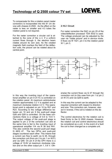
Technology of Q 2500 colour TV setTo compensate for this a rotation panel (rastercorrection) is incorporated into the 81 cm devicewith chassis Q 2500. As the effect on theraster is less on smaller and 4:3 tubes therotation panel is not required.For the raster correction a circular coil is attachedto the cone of the c.r.t. If a uniformcurrent flows through it, the electron beamrotates around its own axis. As the createdmagnetic field overlays the field of the deflectioncoils, the picture can be rotated about itscentral point.2.10.2 CircuitFor raster correction the DAC on pin 25 of thevideo/deflection processor TDA 9332 is used.The voltage produced can be adjusted by theuser via “rotate picture“ and in service mode.It flows via W 1021, pin 3 to the rotation panelW 1, pin 3.R16U12ROTW01123R21R23R11C16C30C23R12C11C17I 01C10+89-C01R36Q26Q28C27 C472 1W31R38 R41R42Q47Q48I 01A+1-C0232C31C124I 0111R39In this way the inverting input of the operationalamplifier on pin 9 of I1C is controlled onthe rotation panel. At maximum anticlockwiserotation approximately 3.2 V is applied and atmaximum clockwise rotation 3.3 V. The operationalpoint is adjusted on pin 10 by R21 andR23. According to the voltage difference betweenpin 10 and pin 9 the push-pull stageQ26 and Q28 is controlled. On the base connectionsthere is a voltage of 0.6 to 10.6 V.The output voltage of the push-pull stage isapplied to pin 2 of the correction coil and atthe same time is fed to the inverting input ofoperational amplifier I1A via R 38 and R41.This also controls the second push-pull stageQ 48/Q 47. The two OPVs and push-pullstages counteract each other. This means thata current can flow to earth via Q 26, throughthe correction coil (from pin 2 to pin 1 on W31)and via Q48. On pin 8 of the OPV there is avoltage of 10.6V at maximum clockwise rotationand on the other output pin 1, 0.6 V. Otherwisethe current flows via Q 47 through thecorrection coil (in this case from pin 1 to pin 2on W 31) and via Q28 to earth.In this way the current can be adapted to therequired correction with respect to directionand size. This correction can, however, alsoact in reverse, if the coil is rotated on the deflector.The control electronics for the rotation coil isfixed firmly to the Q 2500 chassis. However,the rotation coil and control electronics shouldbe considered as a unit. In the event of a faultthe coil is then changed as a complete unit.Document Q 2500 41 © Loewe ProCollege
- Page 1 and 2: Technology of Q 2500 colour TV set2
- Page 3 and 4: Technology of Q 2500 colour TV set1
- Page 5 and 6: Technology of Q 2500 colour TV set1
- Page 7 and 8: Technology of Q 2500 colour TV set1
- Page 9 and 10: Technology of Q 2500 colour TV setF
- Page 11 and 12: Technology of Q 2500 colour TV setS
- Page 13 and 14: Technology of Q 2500 colour TV setQ
- Page 15 and 16: Technology of Q 2500 colour TV setQ
- Page 17 and 18: Technology of Q 2500 colour TV setW
- Page 19 and 20: Technology of Q 2500 colour TV setQ
- Page 21 and 22: Technology of Q 2500 colour TV set2
- Page 23 and 24: Technology of Q 2500 colour TV setD
- Page 25 and 26: Technology of Q 2500 colour TV set2
- Page 27 and 28: Technology of Q 2500 colour TV setC
- Page 29 and 30: Technology of Q 2500 colour TV setW
- Page 31 and 32: Technology of Q 2500 colour TV setV
- Page 33 and 34: Technology of Q 2500 colour TV setT
- Page 35 and 36: Technology of Q 2500 colour TV setJ
- Page 37 and 38: Technology of Q 2500 colour TV setc
- Page 39: Technology of Q 2500 colour TV setL
- Page 43 and 44: Technology of Q 2500 colour TV setO
- Page 45 and 46: Technology of Q 2500 colour TV setI
- Page 47 and 48: Technology of Q 2500 colour TV setc
- Page 49 and 50: Technology of Q 2500 colour TV setF
- Page 51 and 52: Technology of Q 2500 colour TV setF
- Page 53 and 54: Technology of Q 2500 colour TV sett
- Page 55 and 56: Technology of Q 2500 colour TV setS
- Page 57 and 58: Technology of Q 2500 colour TV setP
- Page 59 and 60: Technology of Q 2500 colour TV set3
- Page 61 and 62: Technology of Q 2500 colour TV setB
- Page 63 and 64: Technology of Q 2500 colour TV setr
- Page 65 and 66: Technology of Q 2500 colour TV setA
- Page 67 and 68: Technology of Q 2500 colour TV set-
- Page 70 and 71: Technology of Q 2500 colour TV setT
- Page 72 and 73: Technology of Q 2500 colour TV setI
- Page 74 and 75: Technology of Q 2500 colour TV setT
- Page 76 and 77: Technology of Q 2500 colour TV set4
- Page 78 and 79: Technology of Q 2500 colour TV setC
- Page 80 and 81: Technology of Q 2500 colour TV set4
- Page 82 and 83: Technology of Q 2500 colour TV setQ
- Page 84 and 85: Technology of Q 2500 colour TV setH
- Page 86 and 87: Technology of Q 2500 colour TV setB
- Page 88 and 89: Technology of Q 2500 colour TV setr
<strong>Technology</strong> <strong>of</strong> Q <strong>2500</strong> <strong>colour</strong> <strong>TV</strong> <strong>set</strong>To compensate for this a rotation panel (rastercorrection) is incorporated into the 81 cm devicewith chassis Q <strong>2500</strong>. As the effect on theraster is less on smaller and 4:3 tubes therotation panel is not required.For the raster correction a circular coil is attachedto the cone <strong>of</strong> the c.r.t. If a uniformcurrent flows through it, the electron beamrotates around its own axis. As the createdmagnetic field overlays the field <strong>of</strong> the deflectioncoils, the picture can be rotated about itscentral point.2.10.2 CircuitFor raster correction the DAC on pin 25 <strong>of</strong> thevideo/deflection processor TDA 9332 is used.The voltage produced can be adjusted by theuser via “rotate picture“ and in service mode.It flows via W 1021, pin 3 to the rotation panelW 1, pin 3.R16U12ROTW01123R21R23R11C16C30C23R12C11C17I 01C10+89-C01R36Q26Q28C27 C472 1W31R38 R41R42Q47Q48I 01A+1-C0232C31C124I 0111R39In this way the inverting input <strong>of</strong> the operationalamplifier on pin 9 <strong>of</strong> I1C is controlled onthe rotation panel. At maximum anticlockwiserotation approximately 3.2 V is applied and atmaximum clockwise rotation 3.3 V. The operationalpoint is adjusted on pin 10 by R21 andR23. According to the voltage difference betweenpin 10 and pin 9 the push-pull stageQ26 and Q28 is controlled. On the base connectionsthere is a voltage <strong>of</strong> 0.6 to 10.6 V.The output voltage <strong>of</strong> the push-pull stage isapplied to pin 2 <strong>of</strong> the correction coil and atthe same time is fed to the inverting input <strong>of</strong>operational amplifier I1A via R 38 and R41.This also controls the second push-pull stageQ 48/Q 47. The two OPVs and push-pullstages counteract each other. This means thata current can flow to earth via Q 26, throughthe correction coil (from pin 2 to pin 1 on W31)and via Q48. On pin 8 <strong>of</strong> the OPV there is avoltage <strong>of</strong> 10.6V at maximum clockwise rotationand on the other output pin 1, 0.6 V. Otherwi<strong>set</strong>he current flows via Q 47 through thecorrection coil (in this case from pin 1 to pin 2on W 31) and via Q28 to earth.In this way the current can be adapted to therequired correction with respect to directionand size. This correction can, however, alsoact in reverse, if the coil is rotated on the deflector.The control electronics for the rotation coil isfixed firmly to the Q <strong>2500</strong> chassis. However,the rotation coil and control electronics shouldbe considered as a unit. In the event <strong>of</strong> a faultthe coil is then changed as a complete unit.Document Q <strong>2500</strong> 41 © Loewe ProCollege


