


You also want an ePaper? Increase the reach of your titles
YUMPU automatically turns print PDFs into web optimized ePapers that Google loves.
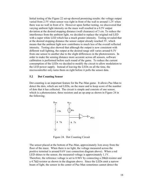
Initial testing of the Figure 22 set-up showed promising results: the voltage outputvaried from 2.5V when sensor was right in front of the wall to around 1.2V whenthere was no wall in front of it. However upon further testing, we discovered thatvarying ambient light intensity on the maze wall resulted in a 0.5V outputdeviation at the desired stopping distance (wall clearance) of 3 cm. To reduce theinterference from the ambient light, we decided to replace the original red LEDwith a super white LED which has a much greater intensity. Testing revealed thatat the desired stopping distance the sensor output already reached 3V, whichmeans that the ambient light now contributes to much less of the overall reflectedintensity. Testing also showed that although the output is now consistent withdifferent wall lighting, the output at the desired range still varies around 0.3Vfrom one sensor to another due to the slight differences in the photoresistors. Inorder to make the sensing distance more accurate across all sensors, softwarecalibration is performed before each round of the game. To reduce the currentconsumption of the LEDs we decided to modify the circuit to allow modulation tothe LED power supply. Instead of leaving the LEDs on all the time, themicrocontroller only turns them on right before it polls the sensor data.5.2 Dot Counting SensorDot counting is an important feature for the Pac-Man game. It allows Pac-Man todetect the dots, which are red LEDs, on the maze and to keep score of the numberof dots that it has collected. The circuit is simple and consists of one sensor,which is a photoresistor, three resistors and an op-amp as shown in Figure 24 inthe following.Figure 24. Dot Counting CircuitThe sensor placed at the bottom of Pac-Man, approximately 3cm away from thefloor of the maze. When there is no light, the voltage measured across thepositive terminal is around 0.6V (see connection diagram above). When a redLED shines to the sensor, the measured voltage is approximately 1.1V.Therefore, the reference voltage is set to 0.96V by connecting a 20kΩ resistor anda 4.7kΩ resistor as shown in the diagram above. Since the LEDs emit a narrowbeam of light, the sensor in the center of Pac-Man sometimes cannot detect the18

