Installation Manual - Mendota
Installation Manual - Mendota
Installation Manual - Mendota

Create successful ePaper yourself
Turn your PDF publications into a flip-book with our unique Google optimized e-Paper software.
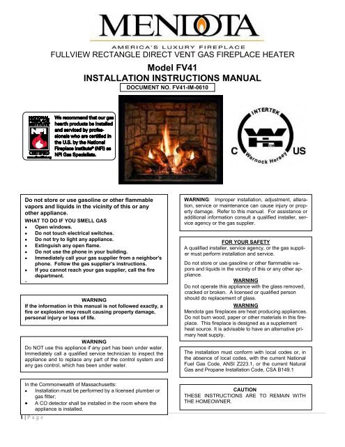
FULLVIEW RECTANGLE DIRECT VENT GAS FIREPLACE HEATERModel FV41INSTALLATION INSTRUCTIONS MANUALDOCUMENT NO. FV41-IM-0610Do not store or use gasoline or other flammablevapors and liquids in the vicinity of this or anyother appliance.WHAT TO DO IF YOU SMELL GASOpen windows.Do not touch electrical switches.Do not try to light any appliance.Extinguish any open flame.Do not use the phone in your building.Immediately call your gas supplier from a neighbor'sIf you cannot reach your gas supplier, call the firedepartment.WARNINGIf the information in this manual is not followed exactly, afire or explosion may result causing property damage,personal injury or loss of life.WARNINGDo NOT use this appliance if any part has been under water.Immediately call a qualified service technician to inspect theappliance and to replace any part of the control system andany gas control, which has been under water.WARNING: Improper installation, adjustment, alteration,service or maintenance can cause injury or propertydamage. Refer to this manual. For assistance oradditional information consult a qualified installer, serviceagency or the gas supplier.FOR YOUR SAFETYA qualified installer, service agency, or the gas suppliermust perform installation and service.Do not store or use gasoline or other flammable vaporsand liquids in the vicinity of this or any other appliance.WARNINGDo not operate this appliance with the glass removed,cracked or broken. A licensed or qualified personshould do replacement of glass.WARNING<strong>Mendota</strong> gas fireplaces are heat producing appliances.Do not burn wood, paper or other materials in this fireplace.This fireplace is designed as a supplementheat source. It is advisable to have an alternative primaryheat supply.The installation must conform with local codes or, inthe absence of local codes, with the current NationalFuel Gas Code, ANSI Z223.1, or the current NaturalGas and Propane <strong>Installation</strong> Code, CSA B149.1In the Commonwealth of Massachusetts:<strong>Installation</strong> must be performed by a licensed plumber orgas fitter;A CO detector shall be installed in the room where theappliance is installed.1 | P ageCAUTIONTHESE INSTRUCTIONS ARE TO REMAIN WITHTHE HOMEOWNER.
TABLE OF CONTENTSSAFETY AND WARNING INFORMATION 2SPECIFIC REQUIREMENTS FOR THE COMMON WEALTH OF MASSACHUSETTS 5FV-41 FULL VIEW GAS FIREPLACE DIMENSIONS 6TECHNICAL SPECIFICATIONS FOR FV-41 7MINIMUM CLEARANCES TO COMBUSTIBLE CONSTRUCTION 7MINIMUM COMBUSTIBLE ROUGH FRAMING DIMENSIONS 7CONGRATULATIONS 8BUILDING PERMIT AND INSTALLATION INSPECTION APPROVAL REQUIREMENTS 8GENERAL APPLIANCE SPECIFICATIONS 9MANTEL CLEARANCES 9CLEARANCES TO COMBUSTIBLES FROM APPLIANCE SURFACES 11PLANNING THE INSTALLATION 12SELECTING APPLIANCE LOCATION 12ROUGH FRAMING DIMENSIONS 13CONSTRUCTING THE APPLIANCE CHASE 13FRAMING DEPTH AND FINISHING GUIDES 14FINISHING GUIDES 14INNER GUIDE 14OUTER GUIDE 14FINISHING MATERIALS INSTALLATION 15TILES AND FAUX ROCK 15MARBLE AND GRANITE SLABS 15HEARTH PROTECTION PAD REQUIREMENTS 16GENERAL INFORMATION 17SAFETY AND STRUCTURAL CONCERNS 17VENTING REQUIREMENTS 17HEATING PERFORMANCE 17AESTHETIC CONSIDERATIONS 17ELECTRICAL REQUIREMENTS 17REMOTE CONTROL RECEIVER LOCATION AND MOUNTING REQUIREMENTS 17GAS SUPPLY REQUIREMENTS 18GAS SUPPLY LINE SIZING 18GAS PRESSURE CHECKING REQUIREMENTS 18GAS PRESSURE REQUIREMENTS 19GENERAL INSTALLATION INSTRUCTIONS 20HIGH ALTITUDE INSTALLATION INFORMATION 20BLOWER OPERATION 20OPERATION DURING POWER OUTAGES 20BACKUP BATTERIES 20GENERAL FLUE VENTING INSTRUCTIONS 21COMPONENT "TWIST-LOCK" CONNECTION PROCEDURE 21EXTERIOR VENT LOCATIONS AND RESTRICTIONS 22FLUE VENTING COMPONENTS IDENTIFICATION 23FV-41 MASTER FLUE VENTING REQUIREMENTS CHART 24IMPORTANT VENTING CONFIGURATION NOTES 25MAXIMUM HORIZONTAL RUN 25MAXIMUM VENT SYSTEM LENGTH 25HOW TO CALCULATE THE VENT SYSTEM LENGTHS 25USING 90 0 25USING 90 0 25USING 45-DEGREE ELBOWS 25APPROVED VENT SYSTEMS 26ZERO RISE HORIZONTAL TERMINATION 27VERTICAL RISE HORIZONTAL TERMINATION 28VERTICAL THROUGH-THE ROOF VENTING 30VERTICAL THROUGH-THE-ROOF VENTING USING FOUR 90 0 ELBOWS 32TO REMOVE DOOR 33TO REPLACE DOOR 33INSTALLATION CHECK OFF LIST 34LIGHTING CHECK OFF LIST 34BLOWER SYSTEM INFORMATION 353 | P age
FLAME APPEARANCE ADJUSTMENT 36FLAME APPEARANCE ADJUSTMENT- AIR SHUTTER ADJUSTMENTS 36FLAME APPEARANCE ADJUSTMENT- EXHAUST DAMPER ADJUSTMENTS 36TROUBLE SHOOTING THE FV-41 FIREPLACE & MAINTENANCE INFORMATION 37OVER FIRING OF BURNER 37MAINTAINING CORRECT PILOT-FLAME, PILOT OUTAGE & RELIGHTING 37CLEANING VIEWING GLASS 37SOOTING 37OPERATION DURING POWER FAILURE 37GAS SHUTOFF PROCEDURE 37MAINTENANCE 38NATURAL TO LP GAS CONVERSION 39Read Before Attempting NG to LPG Conversion 49ORIFICE SIZES REQUIREMENT: 39LP PRESSURE REGULATOR CONVERSION INSTRUCTIONS 40LP GAS PRESSURE REQUIREMENTS 42LPG PROPER INPUT RATES: 42LEAK TESTING REQUIREMENTS 42PILOT FLAME AND MAIN BURNER RELATIONSHIP VERIFICATION 42PILOT FLAME LENGTH ADJUSTMENT 42CHECKING FOR NORMAL BURNER (S) IGNITION CHARACTERISTICS 43ATTACHING LPG CONVERSION LABELS AND HIGH ALTITUDE DERATION LABEL 43FV-41 VALVE ASSEMBLY REPLACEMENT PARTS 44FV-41 GAS IGNITION SYSTEM WIRING DIAGRAM 45GLASS FRAME ASSEMBLY REPAIR AND REPLACEMENT 46TO REPLACE DAMAGED GLASS 46LISTING LABEL INFORMATION 47MENDOTA WARRANTY QUALIFICATION & SERVICE REFERENCE FORM 48MENDOTA EXTENDED LIFETIME PROTECTION AND LIMITED WARRANTY 514 | P age
Specific Requirements for the Common Wealth of MassachusettsThe information in this section applies to all installations performed in the Common Wealth of Massachusetts only.a) For all side wall horizontally vented gas fueled equipment installed in every dwelling, building or structureused in whole or in part for residential purposes and where the side wall exhaust vent termination is less thanseven (7) feet above grade, the following requirements shall be satisfied:1. If there is no carbon monoxide detector with an alarm already installed in compliance with the most currentedition of NFPA 720, NFPA 70 and the Massachusetts State Building code in the residential unitserved by the side wall horizontally vented gas fueled equipment, a battery operated carbon monoxidedetector with an alarm shall be installed in compliance with the most current edition of NFPA 720. NFPA70 and the Massachusetts State Building Code.2. In addition to the above requirements, if there is not one already present, a carbon monoxide detectorwith an alarm and a battery backup shall be installed and located in accordance with the installation requirementssupplied with the detector on the floor level where the gas equipment is installed. The carbonmonoxide detector with an alarm shall comply with 527 CMR, ANSI/UL 2034 Standards or CSA 6.19 andthe most current edition of NFPA 720. In the event that the requirements of this subdivision cannot bemet at the time of the completion of the installation of the equipment, the installer shall have a period ofthirty (30) days to comply with this requirement; provided, however, that during said thirty (30) day period,a battery operated carbon monoxide detector with an alarm shall be installed in compliance with the mostcurrent edition of NFPA 720, NFPA 70 and the Massachusetts State Building Code. In the event that theside wall horizontally vented gas fueled equipment is installed in a crawl space or an attic, the carbonmonoxide detector may be installed on the next adjacent habitable floor level. Such detector may be abattery operated carbon monoxide detector with an alarm and shall be installed in compliance with themost current edition of NFPA 720, NFPA 70 and the Massachusetts State Building Code.3. A metal or plastic identification plate shall be permanently mounted to the exterior of the building at a minimumheight of eight (8) feet above grade directly in line with the exhaust vent terminal for the horizontallyvented gas fueled heating appliance or equipment. The sign shall read, in print size no less than one-half4. A final inspection by the state or local gas inspector of the side wall horizontally vented equipment shallnot be performed until proof is provided that the state or local electrical inspector having jurisdiction hasgranted a permit for installation of carbon monoxide detectors and alarms as required above.(b) EXEMPTIONS: The following equipment is exempt from 248 CMR 5.08(2) (a) 1 through 4:edition of NFPA 54 as adopted by the Board; and2. Product Approved side wall horizontally vented gas fueled equipment installed in a room or structure separatefrom the dwelling, building or structure used in whole or in part for residential purposes.(c) When the manufacturer of Product Approved side wall horizontally vented gas equipment provides a ventingsystem design or venting system components with the equipment, the instructions for installation of theequipment and the venting system shall include:1. A complete parts list for the venting system design or venting system; and2. Detailed instructions for the installation of the venting system design or the venting system components.(d) When the manufacturer of a Product Approved side wall horizontally vented gas fueled equipment does notatisfied:nstallationinstructions; andstemshall include a parts list and detailed installation instructions.(e) A copy of all installation instructions for all Product Approved side wall horizontally vented gas fueled equipment,all venting instructions, all parts lists for venting instructions, and/or all venting design instructions shallremain with the appliance or equipment at the completion of the installation.5 | P age
FV-41 FULL VIEW GAS FIREPLACE DIMENSIONSOVERALL APPLIANCE DIMENSIONS AND FEATURES20 9/16 in19 5/8 in19 5/8 in19 3/16 in9 1/16 in8 1/16 in19 3/16 in40 3/8 in39 1/4 in10 1/8 in19 3/16 in8 1/16 in32 1/2 in23 15/16 in4 7/8 in6 3/8 in13 13/16 in36 3/16 in43 1/16 in43 1/16 in35 in4 7/8 inACCENT LIGHT HOUSING5"X8" COAXIALVENT STARTERCOLLAR5"x8" COAXIALSTARTER COLLARHEAT TRANSFERDUCTS CONNECTIONPORTSLH LIFTHANDLELIFTHANDLECONTROLS ACCESS& INSPECTION PLATEVISIBLE GLASS AREA26-1/4" X 29-1/2"[775 sq. in.]Serial # andLighting InstructionsPlateSEXHAUST DAMPERADJUSTMENTGAS SUPPLYINLET (1/2"MNPT)CONTROLSHARNESSESEXITSTANDING PILOTLIGHT SWITCHFRONT BURNERAIR SHUTTERCONTROLGAS TRAIN,IGNITION SYSTEM,RH BLOWERINSPECTION COVER110VACINLETLH FRAMINGATTACHBRACKETSREAR BURNERAIR SHUTTERCONTROLRH BLOWERINSPECTIONCOVERRH FRAMINGATTACHBRACKETS6 | P age
TECHNICAL SPECIFICATIONS FOR FV-41MODEL FV41High Fire - Adjustable to - Low FireBTUH. (MODEL FV-41) NAT. GAS 40,000 13,000BTUH. (MODEL FV-41) LP GAS 40,000 15,000NOTE: LPG CONVERSION KIT, #New #, MUST BE PURCHASED SEPARATELY TOCONVERT TO BURN LPG IN THIS FIREPLACE.MAIN ORIFICE [0-2000ft (610 m)]: REAR BURNER: #42 NG [#54 L.P.] FRONT BURNER: #42 NG [#54 LP]........................[2000-4500ft (610-1370 m)]: REAR BURNER: #43 NG [#55 L.P.] FRONT BURNER: #43 NG [#55 LP]OVERALL EFFICIENCY: ..................... EXCEEDS D.O.E. EFFICIENCY REQUIREMENTS (A.F.U.E.) FOR DIRECT VENTWALL HEATERS.CO-AXIAL DIRECT VENT FLUE: .......... 5" INNER, 8" OUTERTOTAL WEIGHT: ................................... 225 POUNDSSAFETY: ................................................ AGA/CECERTIFIED IPI AUTO ELECTRONIC IGNITION SYSTEMACTIVATED WITH THERMOSTATIC REMOTE CONTROL.APPLIANCE CERTIFICATION AND TESTING AGENCYINTERTEK TESTING SERVICES, ICBO#AA647-4Certified under ANSI Z21.88 (2005) CSA 2-33 (2005droominstallations and mobile homes. UL307B approved for "mobile homes, after first sale of home, not for recreational vehicles."GAS REQUIREMENTS .......................... SUPPLY PRESSURE: GAS INLET: 1/2" N.P.T.NAT. GAS: 7" W.C. (5" W.C. MIN., 11" W.C. MAX.)L.P. GAS: 11.0" W.C. (11" W.C. MIN., 13" W.C. MAX.)ELECTRICAL REQUIREMENTS ........... 115 VOLT, LESS THAN 1.5 amps (for blower operation only)APPROVED VENT SYSTEMS ............... DURAVENT, SELKIRK, AMERIVENT, SECURITYMINIMUM CLEARANCES TO COMBUSTIBLE CONSTRUCTIONUNIT TO FLOOR 0in. (0mm) GLASS EDGE TO ADJACENT SIDEWALL 18in. (457 mm)UNIT TO ENCLOSURE SIDEWALL 1/2in. (13mm) VENT PIPE TOP TO COMBUSTIBLES 2in. (51mm)UNIT TO ENCLOSURE BACK WALL 1/2in. (13mm) VENT PIPE SIDES TO COMBUSTIBLES 1in. (25mm)UNIT BOTTOM TO ENCLOSURE CEILING 48-1/2in. (123 cm) VENT PIPE BOTTOM TO COMBUSTIBLES 1in. (25mm)UNIT BOTTOM TO ROOM CEILING 72 in. (1829 mm) 18 in. (457 mm)MINIMUM COMBUSTIBLE ROUGH FRAMING DIMENSIONSWIDTH = 42-1/28cm) HEIGHT = 47(110cm) DEPTH = 19-3/16 (49cm)THIS FIREPLACE INCLUDES A SEALED COMBUSTION SYSTEM, 8-PIECE CERAMIC FIBER LOG SET & COALS, FIREBRICKLINED FIREBOX, NEO-CERAM GLASS, ELECTRONIC IGNITION SYSTEM, DUAL BLOWERS, AGA CERTIFIED SAFETY SYSTEM,ACCENT LIGHT and THERMOSTATIC REMOTE CONTROL.OPTIONS: BLACK, VINTAGE IRON, SWEDISH NICKEL, ANTIQUE GOLD, ANTIQUE COPPER HOMESTEAD & WILLOW DOORS,DUCHESS STAINED GLASS FRONT, BOULEVARD DOORS, SERENADE AND PORTRAIT TRIMS and other accessories.CAUTIONTHESE INSTRUCTIONS ARE TOREMAIN WITH THE HOMEOWNER.This appliance may be installed in anaftermarket, permanently located,manufactured home (USA only) ormobile home, where not prohibitedby local codes.This appliance is only for use withthe type(s) of gas indicated on therating plate.NOTE: This installation must conform to local codes. In the absenceof local codes, you must comply with the National Fuel Gas Code,ANSI Z223.1-latest edition in the U.S.A. and the Natural Gas andPropane <strong>Installation</strong> Code, CSA B149 <strong>Installation</strong> Codes in Canada.WARNING: Do not operate this appliance with the glass removed,cracked or broken. A licensed or qualified person should do replacementof glass.HIGH ALTITUDE INSTALLATION INFORMATION: Prior to installing at altitudes higher than 7500, please contactthe <strong>Mendota</strong> technical service department for specific venting requirements and venting restrictions.7 | P age
FV41 DIRECT VENT GAS FIREPLACEGENERAL APPLIANCE SPECIFICATIONSHIGH ALTITUDE INSTALLATION INFORMATION: Prior to installing at altitudes higher than 7500, please contact the<strong>Mendota</strong> technical service department for specific venting requirements and venting restrictions.42 1 2 " MIN.ROUGH FRAMING WIDTH35-1/2"47" MIN.16"TO GUIDE EDGE32 1 8 "NON-COMBUSTIBLE ZONE42 1 2 " MINOPENING WIDTH9" TO VENTPIPE CENTER19-1/2" MIN.DEPTHMINIMUM ROUGH FRAMING DIMENSIONSHEIGHT 47"WIDTH 42-1/2"DEPTH 19-1/2"FROM UNIT BASETO ROOM CEILING72"FROM UNIT BASETO 8" MANTEL48"FROM UNIT BASE TOUNIT ENCLOSURE CEILINGADJACENT WALLS:A wall perpendicular to and in front of this fireplace'sglass door surface must be at least 16 inches from theside edges of the facing guide.A wall at 45° to the glass surface and starting at thisFireplace's outer edge is permitted. Projections behindthis wall (in shaded area) are permitted.4772" MIN.TOROOM CEILING50"8" MANTEL DEPTHAT HEIGHTS SHOWNCEILING48" MIN.19UNIT BASE8 1 "TO 8" MANTEL47" MIN.ROUGH FRAMINGHEIGHT34 7 8 "49 3 4 " 1716 11 "1716 11 "70 5 49 316 " 4 "24" MINTO VINYL SOFFIT(18" MIN TO WOODOR METAL SOFFIT)42-1/2"TO CENTERLINEOF VENT CAP50" MIN.UNIT FLOORTO ENCLOSURECEILINGHEIGHT ABOVECONVECTION AIR OPENING7 1 8 " 7 916 "5 13DISTANCE FROMFIREPLACE FACE16 " 8"16 " 6 1 4 " 6 11516 5 "4 7 8 "416 7 "4"316 9 "3 1 8 "216 11 "2 1 4 "1 1316 "1 3 8 "1516 "12"0"18"17"16"15"14"13"12"11"10"9"8"7"6"5"4"3"2"1"0"FIREPLACE FACE MUST BE COVERED W/NONCOMBUSTIBLE FACING IN THIS AREA.A COMBUSTIBLE MANTEL ONLY ALLOWED INTHIS AREA IF INSTALLED OVERNON-COMBUSTIBLE FACING MATERIAL.NON COMBUSTIBLE FACING12 1 " HEARTH PAD HEIGHT(MIN R-1 RATING)IS REQUIRED!18" min. Non-combustible Hearthprotection required [SEE HEARTHPROTECTION PAD R-RATING, PAGE 12]CAUTION: The distance from floor level to the centerline of the ventcap is given based on Simpson Duravent GS components. If usingvent components of other brands do not assume that themeasurement given here is applicable. Verify the distance tocenterline of vencap by measuring the components you will be using.NOTE: For every 1" this fireplace is raised off the floor,the non-combustible hearth protection pad may be reducedby 2". If this fireplace is raised off the floor more than 6",No hearth protection pad is required.9 | P age
MANTEL CLEARANCESMantel Clearances for this fireplace may be measured from the top of the convection air opening or the floor level ofthis fireplace.The location that is referenced normally to measure mantel clearances is the Top of the Convection Air Opening. Forease, however, measure up from the floor level of this fireplace. The chart and diagram, in this page, provide all the referencedimensional information necessary in determining the distance a combustible mantel may protrude out from the facesurface of this fireplace. The Chart, at right, shows the Distance from Fireplace Face the combustible mantel may protrudeoutward at a Distance up From Floor Level of this Fireplace.If you prefer to take measurements from the Top of the Convection Air Opening, note that the Top of the convection airopening is 30 inches up from the floor level of this fireplace.WARNING: Make proper use of this chart. Do not compromise the specifications contained in this chart.Failure to adhere to proper clearances required to combustibles may cause spontaneous combustion of the mantel andmay result in a fire causing property damage, personal injury or loss of life.Figure 1: Mantel ClearancesNON-COMBUSTIBLE ZONEFIREPLACE FACE MUST BE COVERED W/NONCOMBUSTIBLE FACING IN THIS AREA.A COMBUSTIBLE MANTEL ONLY ALLOWED INTHIS AREA IF INSTALLED OVERNON-COMBUSTIBLE FACING MATERIAL.10 | P age
CLEARANCES TO COMBUSTIBLES FROM APPLIANCE SURFACESFigure 2: Clearances to Combustibles0" CLEARANCEFROM TOP STANDOFFS1/2" CLEARANCEFROM BACK1/2" CLEARANCEFROM SIDES11 | P age
PLANNING THE INSTALLATIONWhen planning on appliance installation, it is necessary to determine the following information before installing:Where the appliance is to be installed.The vent system configuration to be used.Gas supply piping.Electrical Wiring.Framing and finishing details.Hearth Protection Pad Requirements.Whether accessories such as a wall switch, remote control, and ceiling fan are desired.Selecting Appliance LocationWhen selecting a location for your appliance, it is important to consider the required clearances to walls. See Error! Referencesource not found. and Figure 2: Clearances to Combustibles.Figure 3: Planning <strong>Installation</strong>42-1/2 MIN.ROUGH FRAMINGWIDTH51 3 8 " 18"19-1/2"MIN.25 1 4 "17 3 4 "19 1 2 " In addition to these dimensions, also reference:42-1/2" MIN.35 3 8 "42-1/2 MIN.ROUGHFRAMING WIDTHMantel Clearances SectionFraming Dimensions SectionVenting Configuration Section70 3 4 "WARNINGFIRE RISK- ODOR RISKInstall appliance on hard metal or wood surfaces extending full width and depth of this fireplace.An R-1 Rated Hearth Protection Pad [1-e-earth protection pad is required.Do NOT install this fireplace directly on carpeting, vinyl or any combustible material other than wood. Constructchase to all clearance specifications in manual.Locate and install appliance to all clearance specifications in manual.12 | P age
ROUGH FRAMING DIMENSIONSRough Framing DimensionsThe Rough Framing Dimensions must be maintainedto allow this fireplace to slide into the framingcavity with a 90 0 elbow installed on the topstarter collar. After the FV-41 Fireplace is insertedinto the rough framed cavity, install one 2x4 onbody and one 2x4 on top of the top framing standoffsto close the air gap and to act as nailingstuds for finishing materials.Minimum Rough Framing DimensionsDESCRIPTION DIMENSION (INCHES)A Width 42-B Height 47C Depth 19-1/2 D Vent opening height 10-E Vent opening width 10-If the fireplace is to be recessed in a cavity deeper than 19-front face of this fireplace must be of the NON-COMBUSTIBLE variety.Constructing the Appliance ChaseA chase is a vertical box-like structure built to enclose this fireplace and its vent system. Vertical vents that run on theoutside of a building may be, but are not required to be, installed inside a chase.Construction of the chase may vary with the type of building. These instructions are not substitutes for the requirements oflocal building codes. Local building codes MUST be adhered to.Chases should be constructed in the manner of all outside walls of the home to prevent cold air drafting problems. Thechase should not break the outside building envelope in any manner.Wall, ceiling, base plate and cantilever floor of the chase should be insulated. Vapor and air infiltration barriers should beinstalled in the chase as per regional codes for the rest of the home. Additionally, in regions where cold air infiltration maybe an issue, the inside surfaces of the chase may be sheet rocked and taped for maximum air tightness.To further prevent drafts, the fire stops should be caulked with high temperature caulk to seal the gaps. Gas line holesand other openings should be caulked with high temp caulk or stuffed with unfaced insulation. If the appliance is beinginstalled on a cement slab, a layer of plywood may be placed underneath this fireplace to prevent conducting cold up intothe room.Figure 4: FINALIZED Framing DimensionsREMOTE RECEIVERMOUNTING BOX(2-GANG BOX)42-1/2"FLOOR TOWALL THIMBLECENTER43-3/16"FINALIZEDHEIGHT39-1/4"FINALIZEDWIDTH19-1/2"MIN. DEPTH13 | P age
FRAMING DEPTH and FINISHING GUIDESThe framing depth for this fireplaceis 19-1/2 inches. This is a fixeddepth required for all installations,except a corner installation and forinstallations that use solid Graniteor Marble slabs as fascia materials.For corner installations, see figures1 and 4.For installing solid Granite or Marbleslabs as fascia material, reducestuds so that the drywall is flushwith the front face of this fireplace.Install the Granite or Marble slab sothat it adheres to the face of thefireplace and the drywall.Finishing GuidesTwo sets of Finishing Guides aresupplied with this fireplace: One setis called the Outer Guide and theOUTER FINISHINGGUIDES (TOP, L & R)INNER FINISHINGGUIDES(TOP, L &R)other set is cae-with this fireplace.Inner Guide: Identify the Inner Finishing Guides (Top,Left and Right). These guides should be used as aguide for finishing materials if you are planning to installecorativefront or if you are planning to install aor a . Remove and discard the Outer Guides(Top and sides) if you plan to use the Inner Guides.DECORATIVE FRONT TYPE INNER GUIDE OUTER GUIDEFULL VIEW/ NO FRONT USE DISCARDBOULEVARD DOOR KIT USE DISCARDDUCHESS OVERLAY USE DISCARDSERENADE OVERLAY USE DISCARDPORTRAIT OVERLAY USE DISCARDWILLOW DOOR KIT DISCARD USEHOMESTEAD DOOR KIT DISCARD USEOuter Guide: Identify the Outer Finishing Guides (Top, Left and Right). These guides should be used as a guide for fi- or fireplace. Remove and discardonly the Inner Guides (Top and Sides only) if instalthe Outer guides.FV-41 DECORATIVE FRONTS-FINISHING GUIDES SELECTION--SERENADE-USEINNER GUIDE-PIONEER-USEINNER GUIDE-DUCHESS-USEINNER GUIDE-BOULEVARD-USEINNER GUIDE-HOMESTEAD-USEOUTER GUIDE-WILLOW-USEOUTER GUIDE14 | P age
FINISHING MATERIALS INSTALLATIONAll finishing rectangle profile must extend out from the face surface of this fireplace1 inch.Tiles and Faux RockIf installing Tiles or (minimum) Cement Board (Hardibacker or Durock Brand) over theface of the fireplace and framing members. Follow by applying Thinset mortar (no polymer additives) notched trowel on the cement board surface. Finally, install tile to reach a finish material depth of 1 inch.Marble and Granite SlabsIf installing Marble or Granite slabs as fascia materials, specify that the inner edges that will be adjacent to the Glass Doorl on framing members so that its outer surface is flush with the front face ofthis fireplace. Attach Marble or Granite slabs to face of unit and to drywall surface using adhesive that does not offgaswhen hot. [FIGURE 7], only NONCOMBUSTIBLE MATERIALS AREALLOWED.When this fireplace is installed in a framed cavity that is 19-1/2otrudeout into the room 1 inch. Build finishing materials to 1 inch thickness and use the built-in guides for edgealignment of fascia material. DETAIL BSCALE 0.26 : 11.00 INCH FACE OFFV-411" FINISHINGGUIDEWARNING: See Figure 7. The cross hatched areas labeled asncombustiblefinishing materials that is 1-inch thick, minimum. DONOT ALLOW COMBUSTIBLE MATERIALS TO ENCROACH INTHIS AREA!NON-COMBUSTIBLE ZONE[ALL HATCHED AREAS]Figure 6:NON COMBUSTIBLE ZONE [ALL HATCHED AREAS]15 | P age
HEARTH PROTECTION PAD REQUIREMENTSHearth Protection R Rating: MINIMUM R-BOARD (Hardi--1 re--1 rating.All hearth pads must be non-combustible (metal, brick, stone, ormineral fiberboard). Do not use any combustible material toprotect the floor in front of this fireplace. For the FV-41, thehearth protection pad must be rated at R-1 minimum AND itmust extend 18 inches in front of the fireplace face if the FV-41 fireplace is installed at floor level.Use the following procedure to determine if a hearth pad meetsthe requirements listed in this manual. Find the available values,R, K or C and follow the formulae below to arrive at a R value.R-value = Thermal ResistanceK-value = Thermal ConductivityC-value = Thermal ConductanceConvert the specification to R-value;a. If R-value is given, no conversion is needed.b. If K-value is given with for a thickness (t) in inches:R1KTc. If C-value is given:...( 1 divided by K , then multiplied by thickness).R1CDetermine the R-value of the proposed hearth pad. For multiplelayers, add R-values of each layer to determine overall R-value. Ifthe overall R-value of the system is greater than R-1, then theproposed hearth pad is acceptable.Example:Required minimum R value for hearth protection pad is R=1. The- facmineral board with a K-factor of 0.29. Determine if the proposedlayers will provide the minimum R=1 rating.Step A. Use formula to convert C--value.R of the tile:R1= 1/1.25 = 0.80CStep B. Use formula to convert K-factor of mineral board to R-value.R of mineral board:R1KT=1/0.29 x 0.125 = 0.431Step C. Total R-value of proposed alternative:R Total = R tile + R mineral board = 0.8 + 0.431 = 1.231.Step D. Compare proposed system R = 1.231 to required Rof 1.0. Since R of proposed system is greater than therequired R=1, the proposed system is acceptable.Hearth Pad Guide- [Usage and Removal]This fireplace is shipped with a Hearth Pad Guide Installed. The purpose ofthe Hearth Pad Guide is to limit the height of the Hearth Pad during installations.DO NOT build a Hearthpad that is more than 1-so will not allow installation of decorative fronts on this fireplace. After theHearthpad is built, remove the Hearth Pad guide and discard if you do notwish the guide to be visible. In some instances, you will want the guide leftpermanently, based on your aesthetic judgment.To remove the Hearth Pad Guide, first remove the Glass Frame. Identifythe plastic Rivet heads inside the fireplace body. Use a sharp utility knife topry or cut the plastic rivet head and rivet base. Lift the Hearth Pad Spacerupwards and remove.This fireplace may be installed in an elevated position by created anelevated deck and an appropriate framed enclosure. NOTE: Thiss-FRONT12 1 " MAX. THICK HEARTH PAD(MIN R-1 RATING) IS REQUIRED!FIGURE 818" min. Non-combustible Hearthprotection required [SEE HEARTHPROTECTION PAD R-RATING, PAGE 12]NOTE: For every 1" this fireplace is raised off the floor,the non-combustible hearth protection pad may be reducedby 2". If this fireplace is raised off the floor more than 6",No hearth protection pad is required.Figure 7:PRY or CUT RIVET HEAD USING A SHARP EDGE.REPEAT FOR 4 RIVETS.16 | P age
GENERAL INFORMATIONYour <strong>Mendota</strong> Gas Fireplace has a state-of-the-art co-axial direct vent, sealed combustion system. This advanced and highlyefficient system brings in outside air for combustion, has a separate exhaust vent and efficiently heats and re-circulates room air.The <strong>Mendota</strong> system maintains high air quality, maximizes efficiency and assures proper operation in today's "air-tight" homes.SAFETY AND STRUCTURAL CONCERNS:The FV41 Fireplace must be installed and serviced by a <strong>Mendota</strong> approved serviceperson. Any adjustments to burner, pilot,logs or coal bed must be made by a <strong>Mendota</strong> approved service person. If pilot goes out, always wait five (5) minutes beforeattempting to relight pilot.VENTING REQUIREMENTS:This <strong>Mendota</strong> Fireplace can be vented using any available brand DIRECT VENT <strong>Mendota</strong> specified vents and vent caps when installing your fireplace. Closely follow venting locations, directions and requirements.Observe the restrictions relating to vent position on exterior of home (see Figure 12). Be sure all vent pipe sections arefully twist-locked and leak-proof. Be sure 1000º Silicate Stove Sealant is used on the inner pipe joints of all Simpson DuraVentpipe components and all adjustable pipe sections.The <strong>Mendota</strong> Direct Vent Fireplace may be placed within 18 inches of adjacent sidewalls. The fireplace may be placed directlyon concrete or wood flooring. If the appliance is to be installed on carpeting, vinyl or other combustible material other than woodflooring, the appliance shall be installed on a metal or wood panel extending the full width and depth of the appliance. An combustible mantel may be installed at a minimum of 18" above top of the heat outlet (48 up from the floor level of this fireplace)and no more than 8" out from wall at that height. Non-combustible (marble, brick, stone, etc.) mantels can be installed atany desired height above the top convection air opening. Combustible Mantels of any depth with a sheet metal protector plate inits under-side may only be installed outside -Never block off convection air openings or paths. Always use <strong>Mendota</strong> decorative fronts and <strong>Mendota</strong> approved vent systemsand vent caps.A non-combustible hearth protector with a total insulation rating of R-1 is required when installing this fireplace directly on thefloor and must extend a minimum of 18" in front of the fireplace. For every 1 inch the fireplace is raised off the floor, the depth ofthe hearth protector may be reduced by 2 inches. If fireplace is raised off the floor 6" or more, no hearth protector is required.HEATING PERFORMANCE:With its high heat output this <strong>Mendota</strong> Fireplace will heat a large area of your home if located properly to maximize heat/ air circulation.Air movement options for maximizing heat circulation that can be considered are the continuous operation of centralheating furnace blowers or ceiling fans. The most efficient method for overall heat distribution within a single room is aceiling fan. The heat output of the Fireplace can be reduced to a low 13,000 BTUH by turning off the Rear Burner and reducingflame height using the remote control. Blower can be turned down or turned off to reduce heat output.AESTHETIC CONSIDERATIONS:Burning or static fireplaces are a major aesthetic focus in any room. Locate your gas fireplace as you would a television set.The <strong>Mendota</strong> Hearth Gas Fireplace will be a continuing source of comfort and fascination. Corner installations will afford youthe greatest potential for viewing in many rooms. We suggest installing this <strong>Mendota</strong> Fireplace a minimum of 12 inches abovethe floor by utilizing an elevated hearth. This fireplace may be installed in an elevated position as long as 72 in. minimum dis-ELECTRICAL REQUIREMENTS:Electronic Ignition System, Dual Blowers and an Accent Light system areincluded in this <strong>Mendota</strong> Direct Vent Fireplace. These devices requireconstant electrical power except during power outages. A 115-volt electricalservice must be supplied at the fireplace location at the time of installation,on the left side of this fireplace. It must be electricallygrounded in accordance with local codes, or in their absence, with thecurrent edition of the National Electric Code ANSI/NFPA 70. Use of awall switch control in the power supplied to this fireplace is allowed.Thermostatic function is included in the Remote Control Transmitter.Therefore, no Thermostat wire is required.REMOTE CONTROL RECEIVER LOCATION AND MOUNTINGREQUIREMENTSA remote control receiver, a double-gang box and a 10 foot long wireharness are supplied with this fireplace. Plan for mounting the doublegangbox at 4 feet above floor level on the left side of this fireplace. Positionremote receiver about 24 inches on the left side of the fireplace. Donot attempt to locate the receiver on the right side and do not route the10 foot cable on top of this fireplace. The heat on top of this fireplace willdamage the 10 foot cable if you route the cable to the right side.17 | P ageREMOTE RECEIVERMOUNTING BOX(2-GANG BOX)43-3/16"FINALIZEDHEIGHT39-1/4"FINALIZEDWIDTH
GAS SUPPLY REQUIREMENTSCorrect gas pressure and proper gas supply line sizing is imperative to the successful performance of your <strong>Mendota</strong> gasfireplace. Be sure the gas supplier or plumber carefully checks for correct gas pressure and gas line sizing when installingthe fireplace.It is critical to carefully check for gas leaks when hooking up the fireplace -- check with soap & water solution.Be sure to install "approved" flex gas line with brass-to-brass fittings to prevent gas leaks at connections.Gas supply piping must include a drip leg to eliminate the possibility of contaminants entering the gas train.Adhere strictly to local and national codes for entireinstallation.Correct gas pressure and proper gas supply linesizing is required.GAS SUPPLY LINE SIZINGThis <strong>Mendota</strong> Gas Fireplace comes equipped with a 1/2"N.P.T. Female inlet. Gas supply piping must enter theFireplace cabinet on the left side.An approved manual shut-off ball valve, as required bylocal codes must be installed at an accessible location.The appliance and its individual shut-off valve must be disconnectedfrom the gas supply piping system during anypressure testing of that system at test pressures in excessof ½ PSIG (3.5 kPa).The appliance must be isolated from the gas supply pipingsystem by closing its manual shut-off ball valve during anypressure testing of the gas supply piping system at testpressures equal to or less than 1/2 PSIG (3.5 kPa).Figure 8: Gas Supplyand Electrical SupplyInlets Locations110VAC INLET14-2 CABLE REQ'D9 151614 1 4FRONTGAS LINE INLET1/2" FNPT REQ'DA proper gas line diameter must be selected to run from the supply regulator to the Fireplace. Refer to the following tablefor proper gas pipe diameters. Strictly adhere to the correct pipe sizes.12 116WARNING: Never use any type of pipe thread sealants or compounds on the seats of flare or compression connections.PIPE LENGTH(FEET)SCHEDULE 40 PIPEINSIDE DIA.TUBING, TYPE LOUTSIDE DIA.NAT. L.P. NAT. L.P.0-10 1/2" (1.3 cm) 3/8" (1.0 cm) 1/2" (1.3 cm) 3/8" (1.0 cm)10-40 1/2" (1.3 cm) 1/2" (1.3 cm) 5/8" (1.6 cm) 1/2" (1.3 cm)40-100 1/2" (1.3 cm) 1/2" (1.3 cm) 3/4" (2.0 cm) 1/2" (1.3 cm)100-150 3/4" (2.0 cm) 1/2" (1.3 cm) 7/8" (2.3 cm) 5/8" (1.6 cm)150-200 3/4" (2.0 cm) 1/2" (1.3 cm) 7/8" (2.3 cm) 3/4" (2.0 cm)NOTE: Some areas allow coated stainless steel (CSST), copper tubing or galvanized pipe - check with local approvalagencies and codes. NEVER use plastic pipe.GAS PRESSURE CHECKING REQUIREMENTSInlet and manifold gas pressure checking taps are located on gas valve. Perform inlet and outlet pressure tests beforecompleting the facing installation. Remove valve access cover box on left side of fireplace to access the gas valve and allcontrol components.A qualified installer shall take pressure measurements at these ports to verify and set the correct inlet gas pressures duringinitial installation. Outlet gas pressures are factory-set and cannot be field adjusted.NOTE: Check for gas leaks with soap and water solution on all factory joints and field installed joints during first firing ofthis appliance.18 | P age
GAS PRESSURE REQUIREMENTSOne of the main causes of operating problems with gas appliances can be improper gas pressure!Problems such as changes in flame color or configuration, gas pilot or burner outages, intermittent operation, changes inheat output, excessive burner noise, etc. are nearly always the result of changes in gas pressure or improper gas pressureat the time of the installation. The most important item to check during initial installation and the first thing to checkwhen problems occur are the input and output gas pressures!Gas is normally supplied to a residence at 1/2 PSI (13" - 15" W.C.) (3 KPA). A pressure regulator is then placed outsidethe residence, near the gas meter, which drops this pressure to 7" W.C. (1.8 KPA) (Nat. Gas). This "inches to inches"regulator is of adequate capacity to service the gas appliances (such as dryer, furnace, etc.). If this regulator's capacity isnot sufficient to add the Gas Fireplace, an additional "inches to inches" regulator must be installed for the Fireplace.EXCEPTION: Some codes allow 2-PSI (1.4KPA) supplies to enter the residence, in which case "pounds to inches" regulatorsare used.The following table provides information on correct gas pressure requirements. Be sure your gas supplier or plumbercarefully follows this table.GAS PRESSURE REQUIREMENTSDESIREDINLETPRESSUREMINIMUMINLETPRESSUREMAXIMUMINLETPRESSUREMANIFOLDOUTLETPRESSUREAIR SHUTTERPOSITION*NATURAL GAS7.0" W.C.(1.75 kPa)5.0" W.C.(1.12 kPa)11" W.C.(2.61 kPa)3.5" W.C.(0.87 kPa)0 - 1/8 " OPEN(3 mm)L.P. GAS11.0" W.C.(2.75 kPa)11" W.C.(2.75 kPa)13.0" W.C.(3.24 kPa)10.0" W.C.(2.5 kPa)1/4" OPEN MIN.(5 mm)NOTE: For altitudes above 2.000 feet some variations in air shutter settings may be required.Manifold pressure must OUTPUT PRESSURE" tap and inlet pressure at the "INLET PRESSURE" tapwith the burner operating by a qualified installer. Perform pressure tests prior to installing facia material around this fireplace.Figure 9:Gas Valve PressureTest Ports19 | P age
GENERAL INSTALLATION INSTRUCTIONSCAUTION: Each installation must conform to all local, state and national codes. Refer to the national fuel gas code and local zoningand code authorities for details on installation requirements. The <strong>Mendota</strong> Fireplace must be vented to the outside in accordancewith the latest edition of the National Fuel Gas Code. In the absence of local codes, the installation must conform to the most currentedition of the National Fuel Gas Code ANSI Z223.1, also known as NFPA 54. NOTE: The <strong>Mendota</strong> FV-41 Fireplace is approved formobile home and bedroom installations.CAUTION: The <strong>Mendota</strong> FV-41 Fireplace may be installed in a manufactured (mobile) home after the first sale of the home. Manufacturedhome (mobile home) installation must conform with the Manufactured Home Construction and Safety Standard, Title 24CFR, Part 3280, or, when such a standard is not applicable, the Standard for Manufactured Home <strong>Installation</strong>s, ANSI A225.1/NFPA501A, or CSA Z240.4-Gas Equipped Mobile Housing. Consult your local building official. Note: For mobile home installations unitmust be bolted to the floor and properly grounded.The FV-41 Fireplace must be installed by a qualified service person.HIGH ALTITUDE INSTALLATION INFORMATION: Prior to installing at altitudes greater than 7500, please contact the<strong>Mendota</strong> technical service department for specific venting requirements and venting restrictions.1. After selection of the desired fireplace location, prepare the rough opening using framing dimensions on page 10.Be sure to also prepare opening to allow for co-axial vent).2. Check to make certain all venting requirements and locations are being followed.3. This Fireplace is designed for installation into rough framing. NOTE: FRAMING MATERIAL ABOVE FIREPLACEMUST MAINTAIN CORRECT CLEARANCE TO FIREPLACE AND VENT PIPES.WARNING: One-inch clearance to sides & below and inches clearance on top of horizontal vent sections and elbowsare required.4. NOTE: A removable panel in the enclosure for future visual inspection of flue connection is recommended.5. Have an electrician install a 115-Volt supply to the junction box on lower left side of the fireplace cabinet. Connectwires using wire nuts. Make sure the grounding wires are properly connected and that the installation conforms toall local and national wiring codes.6. Have gas supplier or qualified plumber install gas supply line to fireplace and Be sure gas and plumbing instructions (see Page 18 and 19) and all local and national codes are carefully followed.IMPORTANT: Any safety screen, guard, glass, grill etc. removed for servicing this fireplace must be replaced prior tooperating this fireplace.Figure 10: Junction BoxBLOWER OPERATIONThe blower output can be regulated with the remote (included).NOTE: There will be a time delay in bloweroperation during "heat-up" (5 min.) and extended bloweroperation during "cool-down" of unit (12-1/2 min.).OPERATION DURING POWER OUTAGESThe fireplace is designed to operate during power outageson back-up batteries. The blower and Accent Lightwill not operate during the power outage.Backup batteries are located inside the wallmountedremote receiver box. Change the batteriesat least once a year.110VAC INLET14-2 CABLE REQ'D9 151614 1 4FRONTGAS LINE INLET1/2" FNPT REQ'D12 11620 | P age
GENERAL FLUE VENTING INSTRUCTIONSThe <strong>Mendota</strong> Fireplace must be vented using the <strong>Mendota</strong> approved vent system components. Approved brands of ventcomponents include DuraVent, Amerivent, Selkirk and Security vent pipes and venting components. All warranties will bevoided and serious fire, health or other safety hazards may result from any of the following actions: <strong>Installation</strong> by unauthorizedpersonnel; installation of any damaged component; unauthorized modification of vent system; installation of anycomponents not approved by <strong>Mendota</strong>; failure to meet all clearance requirements; failure to properly twist-lock and positivelyseal all components. Consult local building codes before beginning the installation.WARNINGAlways maintain required clearances (air spaces) to combustibles to prevent a fire hazard. Do not fill air spaces with insulation.Check installation instructions for minimum clearance requirements between the outer walls of the vent pipe andnearby combustible surfaces. Be sure to check the vent termination clearance requirements from decks, windows, soffit,gas regulators, air supply inlets, and public walkways, as specified in these installation instructions and local buildingcodes.SAFETY PRECAUTIONS FOR THE INSTALLER: 1) Wear gloves and safety glasses for protection; 2) Exercise extremecaution when using ladders or on rooftops; and 3) Be aware of electrical wiring locations in walls and ceilings.This gas appliance and vent system must be vented directly to the outside of the building, and never attached to a chimneyserving another solid fuel or gas burning appliance. Each direct vent gas appliance must have its own separate ventsystem. Common vent systems are prohibited.To assure proper venting performance of this high-performance <strong>Mendota</strong> Direct Vent Fireplace, it is critical that all brandsof vent pipe sections are sealed tightly and leak-proof. This means that all pipe sections must be carefully rotated into thefully "twist-locked" position.We strongly recommend that fixed length pipe sections be used in place of telescoping sections whenever possible.Note: When using vent pipe and components that do not incorporate a fiberglass or graphite gasket at the inner exhausttube joints, you must use Milpak 1000F silicate stove sealant (#65-06-00909). Aluminum foil tape may be used on theouter (air intake) pipe joint but is not mandatory. Local Codes may vary. Contact your dealer for proper materials.Do not separate telescoping sections. They must be used as complete assemblies.COMPONENT "TWIST-LOCK" CONNECTION PROCEDUREDuraVent and American Metals pipe and fittings are designed with specialtwist-lock connections. Twist-lock procedure is as follows: four (4) indentations,located on the female ends of pipes and fittings are designed to slidestraight in to the male ends of the adjacent pipes and fittings, by orienting thefour pipe indentations so that they match and slide into the four entry slots onthe male ends.Push the pipe sections completely together then twist-lock one section clockwise,approximately ¼ turn until the two sections are fully locked. The femalelocking lugs will not be visible from the outside on the black pipe or fittings.They may be located by examining inside of the female ends.Figure 11: Twist-Lock PipingHIGH ALTITUDE INSTALLATION INFORMATIONPrior to installing at altitudes higher than 7500, please contact the <strong>Mendota</strong> technical service department for specific ventingrequirements and venting restrictions.21 | P age
EXTERIOR VENT LOCATIONS AND RESTRICTIONSFigure 12: Exterior VentA =B =C =D =ALL MEASUREMENTS FROM CENTER-LINE OF VENT CAP- Vent Terminal - Air Supply Inlet - Area where terminal is not permittedClearance above grade, veranda, porch, deck, or balcony(*12 inches (30 cm) minimum). Vinyl surfaces re-Clearance to window or door that may be opened(*12 inches (30 cm) minimum.*Clearance to permanently closed window (minimum12 inches (30 cm) recommended to prevent condensationon window)*Vertical clearance to ventilated soffit located abovethe terminal from the center- (60cm) min.H =I =J =*Not to be installed above a meter/regulator assemblywithin 3 feet (90 cm) horizontally from the center-line ofthe regulator*Clearance to service regulator vent outlet *3 feet (92 cm)minimum.*Clearance to non-mechanical air supply inlet to buildingor the combustion air inlet to any other appliance.12 inches (30 cm) minimum.K = *Clearance to a mechanical air supply inlet 6 feet (1.8 m)minimumE = *C min. L = Clearance above paved side-walk or a paved drivewaylocated on public property (*7 feet (2.1 m) minimum)F = Clearance to outside corner - 7 inches (18 cm). M = Clearance under veranda, porch, deck, or balcony (*12G =Clearance to inside corner - 12 inches (30 cm). Vinylinches (30 cm) minimum )N= an exterior surface, for vertical terminations. A vent shall not terminate directly above a sidewalk or paved driveway, which is located between two single-family dwellingsand serves both dwellings. Only permitted if veranda, porch, deck, or balcony is fully open on a minimum of two sides beneath the floor.* As specified in CGA B1:19 <strong>Installation</strong> Codes (1991). Note: Local codes or regulations may require different clearances.22 | P age
FLUE VENTING COMPONENTS IDENTIFICATIONDO NOT SEPARATE TELESCOPING SECTIONS.USE TELESCOPING SECTIONS AS COMPLETE ASSEMBLIES.HIGH ALTITUDE INSTALLATION INFORMATION: Prior to installing at altitudes higher than 7500, please contact the<strong>Mendota</strong> technical service department for specific venting requirements and venting restrictions.ITEMDESCRIPTION1 2 12" VENT STACK3 24" VENT STACK4 36" VENT STACK5 48" VENT STACK6 90ºGALVANIZED ELBOW45º GALVANIZED ELBOW7 ADJUSTABLE WALL THIMBLE8 ATTIC INSULATION SHIELD 12"9 ROOF FLASHING (0/12 TO 6/12)10 ROOF FLASHING (7/12 TO 12/12)11 STORM COLLAR12 VERTICAL VENT CAP13 SUPPORT BAND14 HORIZONTAL VENT CAP15 FIRE STOP SPACERFigure 13: Flue Venting Components12119,1015131,2,3,4,56171423 | P age
FV-41 MASTER FLUE VENTING REQUIREMENTS CHARTNOTE: THIS CHART IS APPLICABLE TO BOTH NATURAL GAS AND LPG INSTALLATIONS.IMPORTANT NOTES: See Figure 15, below.1. 18 inches maximum horizontal pipe run allowed with a 90 0 llar.2. Maximum Vertical Run allowed is 61 feet.3. Maximum Vent System length allowed is 65 feet.Figure 144. In , 20 feet maximum horizontalrun allowed with a 4 feet starter section. Ifthe starter vertical section is less than 4feet, use the chart and reduce 3 feet forevery 90 0 elbow installed after the first 90 0elbow.5. In , 20 feet maximum horizontalrun allowed only if the first vertical sectionconnected directly to the top of this fireplaceis feet or longer. Three 90 0 elbows may beinstalled anywhere within the 20 feet horizontalrun. No reduction in horizontal is requiredfor the 90 0 elbows used.HIGH ALTITUDE INSTALLATIONINFORMATION: Prior to installing at altitudeshigher than 7500, please contact the <strong>Mendota</strong>technical service department for specific ventingrequirements and venting restrictions.V min H max0 in. 18"6 in. 12 in. 18 in. 24 in. 11'36 in. 154 ft. - 41 ft. 20'41ft. - 61 ft.VariesFOUR 90° ELBOWS MAX IF VERTICALLY TERMINATED IN ZONE "B".THREE 90° ELBOWS MAX IF HORIZONTALLY TERMINATED IN ZONE "B".NOTE: IN ZONE "B", MAXIMUM HORIZONTAL RUN REMAINS 20 FEETREGARDLESS OF THE NUMBER OF 90° ELBOWS USED.ZONE "A"IN ZONE "B" ADJUSTABLE EXHAUST DAMPER MAY BE FULLY OPEN ORFULLY CLOSED.IN ZONE "A", ADJUSTABLE EXHAUST DAMPER MUST BE FULLY OPEN.ZONE "B"24 | P age
IMPORTANT VENTING CONFIGURATION NOTESSee Figure 14 [MASTER FLUE VENTING REQUIREMENTS CHART].HIGH ALTITUDE INSTALLATION INFORMATION: Prior to installing at altitudes higher than 7500, please contact the<strong>Mendota</strong> technical service department for specific venting requirements and venting restrictions.MAXIMUM HORIZONTAL RUNA. Maximum Horizontal Run allowed is 20 feet if a vertical starter section that is between 4 feet to 41 feet is con-B. Maximum Horizontal Run allowed is if a 90-degree elbow is connected dicollar.MAXIMUM VENT SYSTEM LENGTHA. Combined total length of all straight pipe sections in the vent system shall be less than 65 feet.B. Combined total length of all straight pipe sections in the vent system shall be less than 65 feet when using three(3) 90-degree elbows or equivalent and terminating the vent system horizontally.C. Combined total length of all straight pipe sections in the vent system shall be less than 65 feet when using four (4)90-degree elbows or equivalent and terminating vertically.HOW TO CALCULATE THE VENT SYSTEM LENGTHSFor calculation purposes and usage of charts in this manual, simply add the lengths of all individual straight pipe sections.For example: if you use two 2-foot lengths and one 4-foot length, the total vent system length will be 2+2+4 = 8 feet.USING 90 0 ELBOWS The FV-41 Fireplace by MENDOTA allows maximum flexibility in the use of 90 o elbows in the vent system. The length ofthe first straight vertical section directand the number of 90 0 elbows allowed for this fireplace.For vent systems that provide a starting vertical section that is 4 feet or longer, you may connect up to 20 feet of horizontalpipe and up to three (3) 90 0 elbows within the 20 feet run in any configuration and terminate the vent horizontally. Noreduction in horizontal run is required for the elbows used as long as the 4 feet long vertical starter section is connected.USING 90 0 For vent systems that provide a starting vertical section less than 4 feet, the following rules apply:a. You must use the Master Flue Venting Requirements Chart. b. A single 90º vertical-to-horizontal elbow is already calculated into the allowable maximum 20' horizontal run. The VentingRequirements Chart (Figure 14) assumes that for all horizontal runs calculated, one 90 0 elbow is used within the ventingsystem. Each additional 90º elbow reduces the maximum horizontal distance by 3'.c. If you plan to use more than one 90 0 elbow within the vent system, first use the Venting Requirements Chart (Figure 14)and calculate the maximum horizontal run you are allowed based on the first vertical section connected directly to the fireplace.From this maximum horizontal run calculated, subtract 3 feet for each additional 90 0 elbow you will use.Example 1: Assume you are using a 3 feet long starter vertical section. This should allow, per figure 15, 15-1/2 feet ofhorizontal run. If you want to use three 90 0 elbows, subtract 6 feet for two elbows from the 15-1/2 feet maximumallowed [3 feet for each elbow after the first elbow]. This yields 9-1/2 feet as the maximum horizontalrun that you are allowed to install using the 3 foot vertical starter section.CAUTION: If a vertical-to-horizontal discharge elbow or a horizontal-to-horizontal discharge elbow is enclosed within awall, floor or ceiling, a top air space clearance of 2" must be maintained.USING 45-DEGREE ELBOWSTwo 45-degree elbows may be used in place of one 90-degree elbow. On 45-degree runs, one foot of diagonal pipe isequal to 8-1/2 inches horizontal run and 8-1/2 inches vertical run. Two 45-degree elbows may be connected directly tothe vent starter adapter on this fireplace to create an offset to provide the required clearances to combustible framing orsheathing materials.Two 45-degree elbows may be connected directly to the top of this fireplace to create a horizontal offset. 20 feet maximumhorizontal run allowed with this offset configuration only if the first vertical section connected directly to the last 45-degree elbow is more than 4 feet long. For maximum allowable horizontal distances with the 45-degree offsets, see theMaster Venting Configuration Chart.Note: Each horizontally positioned 45º elbow reduces the maximum horizontal distance by 1½ '.SUPPORT: Horizontal runs of pipe will require one vent support for every 3 ft. of pipe.25 | P age
APPROVED VENT SYSTEMSQUICK REFERENCE CHARTFigure 15: Vent SystemsSTRAIGHT UP,VERTICAL VENTINGZERO VERTICALHORIZONTAL TERMINATIONHHVVERTICAL RISEHORIZONTAL TERMINATION61 FEETMAXIMUMAPPROVEDAPPROVEDAPPROVEDVERTICAL RISEDUAL 90° ELBOWSHORIZONTAL TERMINATIONHV2H1H2HVZERO VERTICALDUAL 90° ELBOWSVERTICAL TERMINATIONV1VERTICAL RISEDUAL 90° ELBOWSVERTICAL TERMINATIONVAPPROVEDV2H2APPROVEDVERTICAL RISETRIPLE 90° ELBOWSVERTICAL TERMINATIONV2APPROVEDTHREE HORIZONTAL DISCHARGE90° ELBOWSAPPROVED w/ RESTRICTIONSH1H1VERTICAL RISETRIPLE 90° ELBOWSHORIZONTAL TERMINATIONV1H2V1APPROVEDAPPROVEDAPPROVED26 | P age
ZERO RISE HORIZONTAL TERMINATIONThe FV-41 Fireplace must be installed by a qualified <strong>Mendota</strong> approved serviceperson.A Maximum Horizontal Run allowed is 18 inches if a 90-collar.When a 90-degree elbow is connected directly to this fireplace, the horizontal centerline of the90ºelbow will be 42-1/2Figure 16See Figure 14, MASTER FLUE VENTING REQUIREMENTS CHART and Figure 17 and Figure 16 below.Use "fixed" pipe sections in place of adjustable pipe section s wherever possible. 1000º sealant must be used on ALLinner pipe joints that do not have factory installed gasket material.Always maintain 1" clearance from vent pipe sides and bottom to combustibles, 2" clearance on top of pipe on horizontalruns and on top of horizontal discharge elbows. Do not fill air spaces with insulation or other material.1. Position fireplace in desired location. See Figure 13 for guidelines on proper vent cap placement on the exterior ofhome. Check to determine if wall studs are in the way when venting system is attached. If this is the case, you maywant to adjust the fireplace location or modify the exterior wall framing to allow the vent system to penetrate the wall.2. Measure from the floor level of the fireplace up 45- wall directly at the center of where the vent pipe will penetrate the exterior wall.42-45-1/2"3. Cut and frame a 10-3/4" wide x 10-3/4" high opening in the wall. The hole must be positioned so the vent system willrun level or have a ¼" rise per foot of run AND be perpendicular to the wall. The height of the opening must be locatedto meet all local and national building codes. Do not allow the termination to be easily blocked or obstructed. Ifwall being penetrated is non-combustible material, i.e. masonry block, brick, etc., a 9-inch diameter hole is acceptable.4. Attach the 90-degree elbow to the fireplace starter adapter. Attach a horizontal section to the 90-degree elbow. Besure all vent component connections are in their fully twist-locked position and are leak-proof. Be sure 1000ºsealantis used on the inner pipe joints of all pipe sections manufactured by Simpson DuraVent. The length of the horizontalpiece that fits through the wall will be determined by the location of the fireplace relative to the wall. For a normal installationwhere this fireplace is installed directly against an exterior wall constructed using 2x4 lumber or 2x6 lumber,les from allvent components (2" above horizontal runs and horizontal discharge elbows).5. A wall thimble must always be used when penetrating combustible wall materials.6. From the exterior of the home, slide the horizontal vent cap over the end of the horizontal pipe and tightly secure thecap to the wall with screws. Seal with a high quality caulking.NOTE: Combustible wall thickness must be 4" to 8" maximumNOTE: Vent Cap should not be recessed into wall or siding.ZERO VERTICALHORIZONTAL TERMINATIONH = 18 INCHES MAXIMUMHFigure 17: Horizontal Termination27 | P age
VERTICAL RISE HORIZONTAL TERMINATIONThe minimum vertical section required to be connected directly to the starter adapter on this fireplace is 48 inches whenused with a maximum horizontal run of 20 ft. If the total length of the vertical sections connected directly to the starteradapter on this fireplace is between 4 feet and 41 feet, you are allowed a maximum 20 feet horizontal run. This fireplaceprovides a maximum flexibility in the use of 90 0 elbows when more than 4 feet of vertical starter section is connected tothe starter collar. If 4 feet or more vertical section is connected to the starter collar, you may use three 90 degree elbowsand 20 feet of horizontal pipe sections. No reduction in horizontal run is required for the use of the elbows. For other ventingconfigurations within these maximum limits, see Figure 15, Zone A and Zone B.Combined total length of all pipe sections (include restriction of elbows) in the vent system shall be less than 64 feet.NOTE: The horizontal run of vent pipe must be level or have a ¼" rise for every 1' of run toward the termination. Neverallow the vent to run downward. This will cause high temperatures and the possibility of a fire.This FV-41 Fireplace must be installed by a qualified <strong>Mendota</strong> service person1. Position fireplace in desired location. See Figure 13 for guidelines on proper vent cap placement on exterior of home.Check to determine if wall studs are in the way when vent system is attached. If this is the case you may want to adjustthe fireplace location.2. Locate where vent pipe will pass through any ceilings and will penetrate the outside wall. Since vent pipe sections"overlap" we suggest pre-assembling and measuring the total vent pipe run so you can more accurately locate thepoint where the vent pipe will penetrate the outside wall (See Figure 13). Be sure all vent components are properlytwist locked and leak-proof. Be sure 1000º sealant is used in the inner pipe joints of all pipe sections manufacturedby Simpson DuraVent.3. Cut and frame a 10-- in ceilingopenings. The outside wall hole must be positioned so the vent system will run level or have a ¼" on rise AND beperpendicular to the wall. The height of the opening must be located to meet all building codes and not allow the terminationto be easily blocked or obstructed. A ceiling fire stop spacer is required at any floor (ceiling) opening.4. Connect vent pipe to the fireplace adapter on top of fireplace vent outlet.5. The horizontal pipe must end flush with the exterior wall of the home. Horizontal pipe will require a proper supportevery 3 ft. of vent pipe. THERE MUST BE A MINIMUM OF 1" CLEARANCE TO COMBUSTIBLES FROM ALL VENTPIECES ON THE SIDES AND BOTTOM AND 2" ABOVE HORIZONTAL RUNS).NOTE: DO NOT SEPARATE TELESCOPING SECTIONS.THEY MUST BE USED AS COMPLETE ASSEMBLIES.6. A wall thimble must always be used when penetrating combustiblewall materials.NOTE: Combustible wall thickness must be 4" to 8" maximum.7. From the exterior of the home, slide the horizontal vent cap over theend of the horizontal pipe and tightly secure the vent cap to the wallwith screws. Seal with high quality caulking.NOTE: Venting terminal (Vent Cap) should not be recessed into wallor siding.V H -- see Figure 15Figure 18ONE(1) 90° ELBOWTOP VENTHORIZONTAL TERMINATIONHV28 | P age
Figure 19APPROVEDFigure 2029 | P age
VERTICAL THROUGH-THE ROOF VENTINGThe maximum vertical run of vent pipe is 51 ft. from the top of the fireplace. The fireplace will support a run of a maximumof 61 ft. Maintain 1" air space clearances on all sides of vents (2" above horizontal runs).If an offset is required directly on top of the fireplace, two 45 o elbows may be connected directly to the top of this fireplaceto create a horizontal offset then to run upwards vertically. Doing so will continue to allow the use of the 51 feet maximumvertical run.The FV-41 Fireplace must be installed by a qualified <strong>Mendota</strong> approved serviceperson.1. Place the fireplace in its desired location. Drop a plum bob from the ceiling to the position of the fireplace flue exit.Mark the location where the vent will penetrate the ceiling. Drill a small hole at this point. Next, drop a plum bob fromthe roof to the hole previously drilled in the ceiling. Mark and drill the spot where the vent will penetrate the roof. Determineif ceiling joists, roof rafters or other framing will obstruct the venting system. You may wish to relocate thefireplace or to offset, to avoid cutting load bearing members.2. Cut and frame a 10" x 10" opening in the ceiling centered on the hole drilled in Step No. 1.3. To determine the length of the vent pipe required, measure the distance from the fireplace flue outlet to the ceiling, theceiling thickness and the vertical rise in the attic or second story and allow sufficient vent height above roofline. Fortwo story installations, fire stops are required at each floor level. If an offset is needed in the attic, additional pipe andelbows will be required.4. Assemble the desired lengths of vent pipe and elbows to reach from the fireplace flue outlet. Ensure that all vent pipeand elbow connections are in their fully twist-lock position and that inner pipe joints (DuraVent only) are sealed andare leak-proof. Maintain 1" airspace clearances to combustibles (2" above horizontal runs). Cut a 10" x 10" opening inthe roof, centered in the small drilled hole placed in the roof in No. 1. The opening should be a sufficient size to meetall clearance requirements. Continue to assemble lengths of pipe and elbows necessary to reach up through the roofline.Galvanized pipe and elbows may be utilized in the attic, as well as above the roofline. The galvanized finish isdesirable above the roofline due to its higher corrosive resistance.a) If an offset is necessary, it is important to support the vent pipe every 3 ft. to avoid excessive stress on the elbowsand possible separation. Wall straps are available for this purpose.6. Slip the flashing over the pipe sections protruding through the roof. Secure the base of the flashing to the roof withroofing nails and seal flashing to roof. Ensure the roofing material overlaps the top edge of the flashing. Verify youhave at least the minimum clearance to combustibles at the roofline.7. Continue to add pipe sections until the pipe and the vent cap meet the minimum building code requirements, as outlinedin No. 8 on the following page.a) For multi-story vertical installation, a ceiling fire stop is required at the second floor and any subsequentfloors. The opening should be framed to 10" x 10" inside dimensions as described in step No. 5.8. Any occupied areas above the first floor, including closets and storage spaces, which the vertical vent passesthrough, must be enclosed. The enclosure may be framed and sheet rocked with standard construction materials,however, be sure to maintain minimum allowable clearances between the outside of the vent pipe and the combustiblesurfaces of the enclosure.9. Height "*H" from roof surface to the top of vent cap can be determined as follows:10. Complete installation with storm collar and vent cap."H" DIMENSIONROOF PITCH FEET METERSFLAT to 6/12 2 .67/12 to 9/12 2 .610/12 to 12/12 4 1.213/12 to 16/12 6 1.817/12 to 21/12 8 2.430 | P age
.Figure 2112119,10151361 FEETMAX.1,2,3,4,531 | P age
VERTICAL THROUGH-THE-ROOF VENTING USING FOUR 90 0 ELBOWSIn extreme situations, Four 90 0 elbows may be required to reach a proper exit point for the vent system. <strong>Mendota</strong> hasspent considerable time and effort in the design of this fireplace and its venting system. Through this effort, <strong>Mendota</strong> hasbeen able to certify the use of Four 90 0 elbows.The use of Four 90 0 elbows must meet some minimum prerequisites.Prerequisite #1: The vent system must terminate vertically using a vertical vent cap.Prerequisite #2: There must be a minimum 12 inches of vertical starter section connected directly to the top of this fireplace.Prerequisite #3: For vertical starter sections less than 4 feet tall, you must reduce 6 feet off the maximum horizontal runallowed per Figure 15 on page 21, Zone A.FOUR 90° ELBOWS, VERTICAL TERMINATIONV1(12" MIN.)12"2'3'4'- 40'H1+H2+H33'5'9'24V2 MAX60'58'55'41'V2H1H2H3V132 | P age
FV-41 DOOR OPERATIONTO REMOVE DOOR1. Use the glass latch tool to disconnect the spring latches from the glass frame. Insert tool into hole in latch,pull towards you and Rotate 90 degrees to disengage top latches. Remove tool. There are two springlatches on top of this gas fireplace.2. With both hands, rotate top edge of glass frame away from unit 12 inches.3. Lift glass frame up 1 inch, at an angle, and move away from unit.4. Door is now free from unit.TO REPLACE DOOR1. Line up the three bottom tabs in glass frame bottom with slots in glass clips on firebox bottom. Inserttabs into slots and center tabs in slots, left to right.2. Center Glass Frame over Firebox; left to right.3. After door has been placed into slots, rotate door towards firebox until gasket seal is touching the fireboxframe.4. Use the tool provided to connect the spring latches to the glass frame. Insert tool into hole in springlatch, pull latch towards you, rotate latch so the hook is facing downward then release latch to hook todoor frame.5. Door is now connected and sealed to unit.The following Check-Off Lists must be completed prior to final operation of the Fireplace.1.) INSERT2.) PULL3.) ROTATE4.) RELEASE33 | P age
INSTALLATION CHECK OFF LISTCo-axial vent rigid pipe, wall vent cap or roof vent cap must be installed by a <strong>Mendota</strong>approved person in accordance with instructions. All joints must be secured, "twistlocked"and leak-proof. 1000ºF sealant must be used on the inner pipe joints of all DuraVentpipe sections.Horizontal or vertical vent cap must be installed "right-side-up" and tightly sealed tostructure per instructions. Vent Caps must be <strong>Mendota</strong> approved.Proper exterior and interior clearances for vent systems and locations for wall ventcap/roof vent cap must be maintained.Carefully check for correct gas pressure, proper size gas lines and for gas leaks.115 V electrical service and gas supply must be installed in accordance with instructionsand local and national codes.LIGHTING CHECK OFF LISTAll items on "<strong>Installation</strong> Check Off List" (see above) must be completed.Check for gas leaks and gas pressures prior to installing facing materials.Install fresh batteries in Wall Receiver and remote transmitter. s-Check air shutter opening - 0" to 1/8 Carefully follow all Lighting and Log <strong>Installation</strong> Instructions.Make certain that burners light immediately and flame runs promptly around "curve" inrear burner and lights entire burner. DO NOT proceed with operation unless burnercycles "on/off" without delays.Make certain that the flame is "stable" and does not "lift" off burner. If flame lifts off burner,turn unit off and check that all vent pipes are "twist locked" and leak proof, the ventcap is "right side up" and that 1000º Sealant has been used on the inner pipe joints of allDuraVent pipe sections. DO NOT proceed with operation if flame is "lifting off" burner.Note: Do not separate telescoping sections. They must be used as complete assemblies.Make certain glass door is in proper closed position and "centered" in firebox opening.34 | P age
BLOWER SYSTEM INFORMATIONWARNING: Label all wires prior to disconnection when servicing controls. Wiring errors can cause improperand dangerous operation. Verify proper operation after servicing.This appliance is equipped with a three-prong (grounding) plug for protection against shock hazardand should be plugged directly into a properly grounded three-prong receptacle. Do not cut or removethe grounding prong from the plug.Dual blowers are provided as standard equipment with this FV-41 fireplace. The dual blowers have an air output ratingof 210 CFM (in free air). This fireplace is designed to operate with the blowers turned OFF or ON. Turning the bloweron increases the overall efficiency of this fireplace and aids in distributing and circulating heat to the room this fireplaceis installed in.BLOWER OPERATIONThe remote control system supplied with this appliance can turn the blowers ON or OFF and regulate the speed of theblowers in six(6) steps.NOTE: In the Normal Thermostat Mode and the SMART Mode, there will be a time delay in blower operation during"heat-up" (5 minutes) and extended blower operation during "cool-down" of unit (12-1/2 minutes).FV-41 BLOWER WIRING DIAGRAMBLOWER MODULE ON/OFF POWER SWITCH INDICATOR SYMBOLS __ INDICATESINDICATES35 | P age
FLAME APPEARANCE ADJUSTMENTAIR SHUTTER ADJUSTMENTSBe sure burner and logs are properly installed (see FV-41 Log Set <strong>Installation</strong>Section). After burner has been properly installed and operatedfor 20 minutes, small additional adjustments to the air shutter maybe necessary for final flame appearance. These small shutter adjustmentscan be made by following these procedures: fortterscan be manipulated with the fireplace operating. Opening theshutter will yield shorter and blue(er) flames and closing the shutter willyield taller and yellow(er) flames.The front burner air shutter adjustment lever is located below the GlassThe rear burner air shutter adjustment lever is located below the Glass1. Install logs and glass frame, and burn unit for 20 minutes2. If flame is too "blue" open Air Shutters until flames turn yellow.3. If flames are too "orange" or are causing sooting, open Air Shuttersuntil flames begin to turn blue. NOTE: If sooting does not stop, turn off fireplace & call a <strong>Mendota</strong> Service Person.IMPORTANT: Try each new shutter setting for approx. 1/2 hour before making additional changes.NOTE: Changes in front burner flame can be made by re-arranging the coals as well. Densely packed coals will yieldmore glow and blue flames. Loosely packed coals will yield less glow and yellow flames.4. For NG applications, start wineed to be open further.5. need to be opened further.VENT DAMPER ADJUSTMENTSThis fireplace is equipped with a vent damper system that can be adjusted using the glass latch tool. Locate damper adjustmentrod above the glass frame in convection chamber at the center. terminated verti-NOT CLOSE the vent damper completely. Adjust position of damper by judging the flame characteristics after 20 minutesof burn time. If the flames ghost off burners or if sooting occurs [in LPG units], open the vent damper FULLY and workbackwards in increments to determine the correct damper position for that particular installation.Use a flash light to look into the convection air cavity and note the Damper Position Indicator. Hook glass latch tool in thehole at the end of the damper rod, , release. Use aflashlight to inspect the damper position. The base of the damper adjustment rod has a pointer that indicates the positionof the damper.90°CLOSEOPENFRONT BURNERAIR SHUTTEROPENACCENTLIGHTHOUSINGCLOSEREAR BURNERAIR SHUTTERDAMPERPOSITIONINDICATORCCW OPENSDAMPERCW CLOSESDAMPERPULL OUT 1/8"ROTATE CLOCKWISE,RELEASE.Hook LatchTool In Hole.36 | P age
TROUBLE SHOOTING THE FV-41 FIREPLACE & MAINTENANCE INFORMATIONSYMPTOM PROBABLE CAUSES CORRECTIVE ACTION1. Thin black coating(soot) forms on viewingglass.2. Humming or whistlingcoming from Fireplace.3. A change in flame appearanceor burner operation.A. Incorrect gas pressureB. Not enough combustionairHave gas supplier check for correct gas inlet pressure (7" W.C. Nat. Gas; 11"W.C. LP Gas).If sooting continues, open air shutter on burner (see "Gas Flame Adjustment"below).If sooting still continues, shut off unit and call <strong>Mendota</strong> service person.NOTE: To clean glass - remove glass and wipe glass with cloth or paper towel.A. Normal operating noise. Some noise is normal. It is caused by the gas supply flowing through the gasorifice. It is expected from any gas fireplace. Turning the Hi/Lo Knob on thecontrol can reduce the noise. Turning down the flame will reduce the heatoutput of the unit.A. A change in gas pressure.B. Vent system restricted.Have your gas supplier check for correct gas 7" W.C. Nat. Gas; 11" W.C. LPGas). If flame still needs adjustment see "Flame Adjustment" below.Clean out carbon, spider webs, lint, etc. from shutter area.Logs and burner. AIR INTAKE and Exhaust OUTLET ports.OVER FIRING OF BURNERNEVER "over fire" units by adjusting gas pressure or drilling out the orifice to increase BTUH above nameplate specifications.Over firing can cause permanent damage to firebox and deterioration of parts and void warranty.MAINTAINING CORRECT PILOT-FLAME, PILOT OUTAGE & RELIGHTINGThe pilot flame must be checked during initial installation and annually by a qualified <strong>Mendota</strong> Technician. This applianceutilizes Flame Rectification Technology. If the pilot flame is turned down too low, the flame sensor may not detect the pilotflame and the pilot light may not stay lit. Do not turn down the pilot light flame. Use the IPI mode instead during summermonths.CLEANING VIEWING GLASSThe viewing glass should be cleaned periodically. Exterior glass surface may be cleaned with cleaner as desired. Toclean interior surface of glass - use soap and water. CAUTION: Do not use oven cleaner to clean glass. Clean the glassonly when it has cooled to room temperature.NOTE: Additives that are put in gas (both natural and propane) to make it smell can be harmful to glass and can leave a# 65-06-00455) or comparable product (contact your dealer).In some cases (especially when burning f the glass. This is not acommon occurrence is not covered under the warranty. The solution maybe to change propane suppliers.SOOTINGSooting is caused by improper installation or air shutter operation. However, some small areas of soot deposits on logsurfaces are deemed acceptable. If you observe large sothe door glass (usually a thin black film on the Fireplace viewing glass or on the outside of the home around the vent cap),the unit must be immediately turned off and the local <strong>Mendota</strong> dealer promptly informed. <strong>Mendota</strong> dealers will correct"sooting" problems, but <strong>Mendota</strong> and their dealers are not responsible fordamage caused by excessive sooting that has not been immediately broughtto their attention.OPERATION DURING POWER FAILUREThis fireplace is designed to operate during power outages. Blowers and theAccent Light will not function during power outages. However, all burners willcontinue to function normally. Heat output will be reduced slightly without theblower functioning (approximately 5% less).GAS SHUTOFF PROCEDURESThis gas fireplace is equipped with a manual ball shutoff valve that is locatedon the left side and within the left convection air cavity. The manual ball shutoffvalve is designed to be manipulated using the glass latch tool. Insert bent endhead) and rotate ball valve downward to OFF or upward to ON.ONOFFBALLVALVEHANDLE37 | P age
MAINTENANCE1. ANNUAL MAINTENANCE OF MENDOTA UNITS IS REQUIRED. The following procedures must be performedeach year by a <strong>Mendota</strong> approved service person. NOTE: Any adjustments to burner, pilot or logs must be doneby a qualified <strong>Mendota</strong> service person.A. Clean all lint and dust build-up around the control. Inspect the condition of any wiring under the burner for meltingor damage.B. Remove logs & coals and clean away any foreign matter (lint, Carbon, etc.) on the burner and logs. Be sure theburner ports are "open". Clean the pilot and under side of the logs for any Carbon deposits. NOTE: Logs shouldbe visually checked for Carbon "build-up". If carbon deposits are visible on logs, unit should be turned off and<strong>Mendota</strong> service person contacted. Be sure logs are re-installed per instructions on PAGE 34.C. Check condition of glass door gasket, gasket must seal tightly over firebox, replace if necessary.D. Periodically check to verify that the vent system and vent cap areopen and free of blockage.1" MIN.E. Before re-installing glass, have qualified service person check theoperation of the pilot with millivolt meter and cycle the burner perLIGHTING INSTRUCTIONS (see PG. 43). Be sure all items inLIGHTI1. The viewing glass should be cleaned periodically. Exterior glasssurface may be cleaned with cleaner as desired. To clean Interiorglass surface, use Kel Kem -06-00455) orcomparable product. Do not use oven cleaner or abrasive cleanersto clean glass. Do not clean when glass is hot.2. Periodic visual check of pilot flames is required. Pilot Flame mustoverlap Flame Sensor and burner ignition ports at all times.3. Periodic visual rear and front flames is required.1" MIN.1" MIN.BURNER FLAMES GENERAL HEIGHTS REFERENCE DIAGRAMHOODSPARK RODFLAME SENSOR38 | P age
NATURAL TO LP GAS CONVERSIONKit # HA-78-00179 for <strong>Mendota</strong> Model FV-41This conversion kit shall be installed by a qualified service agency in accor-codes and requirementsof the authority having jurisdiction. If the information in these instructionsis not followed exactly, a fire, explosion or production of carbonmonoxide may result causing property damage, personal injury or loss of life.The qualified service agency is responsible for the proper installation of thiskit. The installation is not proper and complete until the operation of the convertedappliance is checked as specified in the owner instructions suppliedwith the kit.REMOVE LOG GRATECaution: The electrical supply to the fireplace must be turned off prior to performingthe conversion. The gas supply must be shut off prior to disconnectingthe electrical power.ORIFICE SIZES REQUIREMENT:A Natural Gas to LPG conversion kit #HA-52-00145 must be ordered and installedto convert the FV-41 Fireplace to burn LPG.LP Conversion Kit #HA-78-00179 contains the following parts: One MotorizedLP Pressure Regulator, One LP Pilot Orifice Thimble, and two Cap Orificesdrill #54.Recommended Procedure To Convert This Fireplace To Burn LPGThis fireplace arrives from the factory ready to burn Natural Gas. If you intend toburn LPG, it is highly recommended that you convert this fireplace and itsPressure Regulator, Pilot Orifice Thimble and Burner Orifices prior to placingthis fireplace in its framed cavity.LIFT UP ANDREMOVEFLOOR PANELSREMOVE SCREWSFIRST.See diagrams, on this page, and follow these instructions to prepare this fireplacefor conversion to LPG.place. Remove Grate from Firebox.2. Remove the Floor Brick Panels by lifting them out of the firebox.3. Carefully remove Left Brick Panel. Push rear end of Baffle Brick upwardabout ¼ inches and hold in place with right hand. Tip Left Brick Panelinward using left hand and carefully release left side panel and guide itout of firebox.1. PUSH REAR ENDOF BAFFLE BRICKUPWARD ABOUT1/4 INCHES.2. TIP LEFT BRICKPANEL INWARDAND RELEASECAREFULLY.FLOOR PANELS1.REMOVE 8 SCREWS THAT SECURE LEFTBLOWER ASSEMBLY COVER TO LEFT SIDE OFFIREBOX.2. SLIDE BLOWER & COVER PLATE INTO FIREBOX.DISCONNECT BLOWER WIRES & REMOVEBLOWER ASSEMBLY.BLOWERASSEMBLY39 | P age
WARNING: It is of the utmost importance that the correct burner orifices be installed for both the rear and frontburners.It is highly recommended that you remove the left side blower assembly and the left side exterior controls boxbefore attempting to replace the pressure regulator.1. Turn off gas supply at the appliance service valve.2. See diagrams on this page and identify the Pressure Regulator on theValve Body.3. Using a Torx T20 or a slotted screwdriver, remove 2 screws that securethe NG Pressure Regulator to the gas valve body and removeNG Pressure Regulator, see following page.4. Install the new LP Pressure Regular onto the gas valve body in thesame position and orientation as the NG Pressure Regulator you removedin Step 2, above. The LP Pressure Regulator can only bemounted in one position. Secure the LP Pressure Regulator in place.Tighten down.5. Remove both Rear and Front Burners. Locate and Identify the RearBurner Orifice Spud and the Front Burner Orifice Spud. Both Frontwell socket and ratchet.6. Install Rear Burner Orifice #65-14-00054(#54 drill) for the Rear Burner.Tighten down securely.7. Install Front Burner Orifice #65-14-00054 (#54 drill) for the FrontBurner. Tighten down securely.7. Install pilot orifice thimble #05-04-5 for location.To remove Pilot Hood, use a screw driver to pry open the WireVIEW FROM OUTSIDE FIREBOXPRESSUREREGULATORClip that is located at the base of the Pilot Hood. Pull Upward and remove pilot hood. Use an Alan wrench to removeNG Pilot Orifice. (Pilot orifice thimble is located inside pilot hood base).8. Install LP Pilot Orifice. Tighten down using an Alan wrench. Replace Wire Clip in its original position.9. Push Pilot Hood down into base until it snaps in place.Pull Pilot Hood UPand lift UP off the base.MotorizedLP PressureRegulator[10.0-5.5"WC]Use an Alan WrenchTo loosen and removeNG Pilot Orifice. InstallLP Pilot Orifice, TightenDown.WIRECLIP.Burner Orifices[#54 X2]LP Pilot OrificeORIFICEWASHERS (2)3/8" COMP X 1/8NPTBRASS FITTINGMOTORIZED PRESSUREREGULATORREAR ORIFICEINSIDE HERE.FRONT ORIFICEINSIDE HERE.PILOT LIGHT HOOD40 | P age
LP PRESSURE REGULATOR CONVERSION INSTRUCTIONSWARNING: Failure to position the parts in accordance with these diagrams or failure to use only parts specificallyapproved with this appliance may result in property damage or personal injury.41 | P age
LP GAS PRESSURE REQUIREMENTSInlet and manifold gas pressure checking taps are located on gas valve. These ports are only accessible from the outerleft side of the fireplace. A qualified installer shall take pressure measurements at these ports to verify and set the correctgas pressures during the LP Kit installation and before facia materials are installed over the front of this fireplace. Manifoldpressure must with theburner operating by a qualified installer.DESIREDINLETPRESSUREMINIMUMINLETPRESSUREMAXIMUMINLETPRESSUREMANIFOLDOUTLETPRESSUREAIR SHUTTERPOSITIONL.P. GAS11.0" W.C.(2.75 kPa)11" W.C.(2.75 kPa)13.0" W.C.(3.24 kPa)10.0" W.C.(2.5 kPa)1/4" OPEN MIN.(5 mm)REGULATE THE FLAME HEIGHT TO "HIGH" POSITION. OUTLET GAS PRESSURES MAY VARY PLUS OR MINUS 5%.LPG PROPER INPUT RATES:With the proper orifices installed, as specified above, thisfireplace utilizing LP Gas will have a maximum input rate of40,000 Btu/Hr.LEAK TESTING REQUIREMENTSPrior to completing the conversion process, check for gasleaks with soap and water solution at all plumbing jointsprior to placing this appliance into operation. It is recommendedthat all gas-plumbing joints, factory installed andfield installed are checked for leaks.PILOT FLAME AND MAIN BURNER RELATIONSHIPFigure 23: Pressure Test PortVERIFICATIONPrior to completing the conversion process, the qualifiedservice technician must, light the pilot light and verify the relationship between the pilot light flames and the main burners.The pilot light flames directed towards the propagation ports on the rear and front burner must overlap the propagationthe rear and front burners as shown in the diagram, below. Verify that the burner tubes ignite quickly and the burnerflames propagate smoothly along the entire length of the burners.PILOT FLAME LENGTH ADJUSTMENTIf the pilot light flame length is too short and the system does not maintain a standing pilot, a qualified installer mayincrease the length of the pilot light flames to meet the two requirements: Minimum pilot light length to maintain astanding pilot light and the pilot light flames must be long enough to overlap the front and rear burner ports.1" MIN.1" MIN.Pilot Flamemust overlapBurner Ports1" MIN.42 | P age
CHECKING FOR NORMAL BURNER (S) IGNITION CHARACTERISTICSOnce the conversion to LPG and all the above steps have been completed, light the main burners.Turn Gas Dial counterclockwise to "ON" then set Thermostat or push Main Burner ON/OFF switch to turn on burners.Main burner should now light IMMEDIATELY and flame should not "lift" off burner. If there is any delay in ignition or ifflame is "lifting off" burner, turn off burner and carefully check for proper installation of logs/coals, vent system and properpilot flame impingement on burner. Logs or coals must not block pilot flame or main burner flame. Vent system must beleak proof.WARNINGDO NOT PROCEED WITH OPERATION OF THIS FIREPLACEUNLESS BURNER "CYCLES" ON/OFF WITHOUT DELAYS!ATTACHING LPG CONVERSION LABELS AND HIGH ALTITUDE DERATION LABELTwo printed informational labels are included with the LPG Conversion Kit. Attach these two labels to the back surface ofthe Serial Number Plate that is located in the convection air cavity below the firebox. If you are derating this appliance at ahigh altitude, also attach the High Altitude Prior to attaching the labels, fill in all the information that is requested in these labels.For installations from 610-1370 meters (2000-4500 ft.) the orifice sizes (DMS) for natural and propane gas are_43_ and _55_, respectively. See data plate for additional information. For high altitude installations consultthe local gas distributor or the authority having jurisdiction for proper rating methods. If the installer must convertthe unit to adjust for varying altitudes, the information sticker must be filled out by the installer and adheredto the appliance at the time of conversion."«Cet appareil est equipé pour des altitudes compries entre 0 et 2000 pieds (0-610 m) seulement»This appliance has been converted for use at an altitude of ______________Orifice size _______________ Manifold Pressure ________________Input (Btu/h)_______________ Fuel Type _______________________Date of conversion _________ Converted by _____________________«Cet appreeil a été converti au ____Injecteur ________Pression à la tubulure d'alimentation _____________Déoit calorifique ______________43 | P age
FV-41 VALVE ASSEMBLY REPLACEMENT PARTSFV-41 VALVE ASSEMBLY REPLACEMENT PARTS LISTITEM QTY PART NUMBER DESCRIPTION1 1 HA-77-00159 VALVE HEAT SHIELD2 2 65-07-00024 1/8 NPT to Flex CF Coupler3 1 05-04-00050 SIT Pilot Assembly4 2 65-14-00042 ORIFICE, #42 22,197 BTU NAT5 1 05-02-00344 885 PROFLAME SIT VALVE6 1 05-02-00351 Solenoid, 885 PROFLAME SPLIT FLOW VALVE7 1 60-01-00018 NIPPLE, 3/8" NPT X 1.5" LONG, 0.493 ID, BLACK8 1 65-07-00753 Elbow 90 Deg, 3/8 Flared Tube X 3/8" NPT Male, Brass9 2 65-07-00012 BCF,3/8 TBE X 3/8MPT COMP ELBW10 1 55-02-00089 3/8" FLARED FLEXTUBE, SS X 9"11 1 55-02-00073 TUBING, 3/8" OD X 10" SS 30412 1 55-02-00088 TUBING, 3/8" OD X 30" SS 304Figure 24: FV-41 VALVE ASSEMBLY44 | P age
FV-41 GAS IGNITION SYSTEM WIRING DIAGRAM45 | P age
GLASS FRAME ASSEMBLY REPAIR AND REPLACEMENTDO NOT substitute other manufacturer'smaterials or components.DO NOT operate unit with cracked,broken or missing glass.DO NOT abuse the glass door bystriking the glass, slamming thedoor shut, etcWARNINGUse only authorized parts andmaterials obtained from JohnsonGas Appliance Company whenreplacing defective or damagedglass.WARNINGDo not operate this appliancewith the glass removed, crackedor broken. Glass should be replaceby a licensed or qualifiedperson.TO REPLACE DAMAGED GLASS1. Bend Glass Retainer Tabs up 90 degrees. Four tabs hold down the glass and gasket assembly.2. Remove the damaged glass and gasket material. Clean the inner surface of the glass frame.3. Assemble new gasket on glass edge starting with the bottom left corner. The adhesive on the gasket shouldmake contact with the glass surface. Use tracer lines in gasket to determine where the glass should sit on thegasket surface. See Figure 263.4. Place glass and gasket assembly in glass frame and carefully bend down glass retainer tabs. Extra glass retainertabs are provided should any originally used tabs break off.Figure 25The glass frame assembly and its individual components are availablethrough Johnson Gas Appliance Company. Contact your dealer for moredetailed ordering information.TAB #2GLASS FRAME ASSEMBLY # HA-78-00103REPLACEMENT PARTS LISTITEM PART NUMBER DESCRIPTION1 HA-78-00XXXFRAME, WELDMENT, GLASS,FV-412 65-02-00103GASKET, TADPOLE,3 65-06-01184 GLASS, CERAMIC, FV-41GASKETFigure 27GLASSROTATE GASKET UPSO ADHESIVE MAKESCONTACT WITH GLASSSURFACEFigure 26USE LARGE PLIERS TOBEND DOWN (4) TABSAS SHOWNGASKETGLASSGASKET INFLAT FORMTRACER LINESIN GASKETADHESIVE46 | P ageGLASS SHALL SIT BETWEENTRACER LINES IN GASKET
LISTING LABEL INFORMATIONThe model information regarding your specific appliance can be found on the rating plate, which is located inside the rightside controls access door. When contacting your dealer for any cleaning service or warranty service, always provide theModel Number, Serial Number and Manufactured Date. This information will expedite the warranty verification process.47 | P age
MENDOTA WARRANTY QUALIFICATION & SERVICE REFERENCE FORMAs a part of <strong>Mendota</strong>'s on-going program of customer satisfaction, this Form verifies proper installation and operation. It is importantas a reference for future service. It insures long life and trouble-free operation of <strong>Mendota</strong> fireplaces & stoves and qualifiesthe owner for <strong>Mendota</strong>'s lifetime limited warranty. Owner should sign Form when completed and mail a copy along withWarranty Registration to <strong>Mendota</strong>. OPTIONALLY, PLEASE REGISTER AT OUR WEBSITE AT:WWW.JOHNSONGAS.COM/MENDOTA-REGISTRATION.ASPHOME OWNER: ________________________________ADDRESS: ____________________________________CITY/STATE/ZIP: ______________________________DEALER: _________________________________ADDRESS: _______________________________CITY/STATE/ZIP: __________________________SIGNATURE: __________________________________ PHONE: __________________________________MODEL #: FV-41 SERIAL #: _______________ DATE INSTALLED: ________________________<strong>Mendota</strong> direct vent fireplaces are sophisticated, hi-tech gas appliances. All installation and operating instructions must be carefullyfollowed. This FV-41 fireplace must be installed and serviced by a qualified <strong>Mendota</strong> approved service person.REF: ___________________ MENDOTA FV-41 INSTALLATION MANUALAPPROVED VENT PIPES AND VENT CAP INSTALLED - Per <strong>Manual</strong>.Vent pipes must be fully twist-locked and leak proof.Check minimum and maximum vertical / horizontal and vent runs.1000ºsealant must be used on inner joints at adjustable pipe sections.CHECK FOR PROPER CLEARANCES TO COMBUSTIBLES & VENT LOCATIONS - Per <strong>Manual</strong>INSTALL PROPER SIZE GAS LINES - CHECK FOR GAS LEAKS - Per <strong>Manual</strong>CHECK FOR CORRECT GAS PRESSURE AT MANIFOLD - Per <strong>Manual</strong>a. 3.5 Inches Water Column Maximum - Nat. Gasb. 10.0 Inches Water Column Maximum - L.P. GasCYCLE BURNERS ON/OFF FOR PROMPT IGNITION - Per "LIGHTING INSTRUCTIONS"Burner must light IMMEDIATELY - Flame must travel promptly around "curve" & light burner.INSTALL LOGS AND ADJUST FLAME - Per <strong>Manual</strong>Proper pilot flame impingement on burner - Air shutter opening: 1/8" Nat. Gas 1/4--1/2" LPCheck that flame is "stable" and is not "lifting" off burnerBRIEF OWNER ON OPERATION AND MAINTENANCE OF UNITLight Pilot Operate Burner Train on Remote Control Functions Explain Thermostatic FunctionsWARRANTY REGISTRATIONYour Name _______________________________________________________________________Address _________________________________________________________________________City ________________________________________ State ______Zip ______________________Dealer (Place of Purchase) ___________________________________________________________City ________________________________________ State ______Zip ______________________Date of Purchase _______________________ Serial Number _______________________________Purchaser's Signature _______________________________________________________________MENDOTA FV-41 DIRECT VENT FIREPLACECUT OUT PAGE AND MAIL TO: JOHNSON GAS APPLIANCE CO., 520 E AVE. N.W., CEDAR RAPIDS, IOWA 52405PLEASE REGISTER AT OUR WEBSITE AT: WWW.JOHNSONGAS.COM/MENDOTA-REGISTRATION.ASP48 | P age
49 | P ageNOTES
TAPE SHUT-------------------------------------------------------------------------------------------------------------------------------------------------------------POSTAGENEEDEDJOHNSON GAS APPLIANCE COMPANY520 E AVENUE N.W.CEDAR RAPIDS, IA 5240550 | P age
MENDOTA EXTENDED LIFETIME PROTECTION AND LIMITED WARRANTYMENDOTA FV-41 DIRECT VENT FIREPLACE<strong>Mendota</strong> Division of Johnson Gas Appliance Company, 520 E Avenue N.W. Cedar Rapids, Iowa 52405, extends this Extended Lifetime Protection and LimitedWarranty to the original purchaser of a <strong>Mendota</strong> FV-41 Fireplace, which is limited and used under normal home conditions.STANDARD WARRANTY:JOHNSON GAS APPLIANCE CO., MENDOTA DIVISION, WARRANTS THAT YOUR NEW MENDOTA FIREPLACE IS FREE FROMMANUFACTURING AND MATERIAL DEFECTS FOR A PERIOD OF ONE YEAR FROM THE DATE OF INSTALLATION, SUBJECT TO THEFOLLOWING CONDITIONS AND LIMITATIONS:EXTENDED LIFETIME WARRANTY:THE HEAT EXCHANGER, BURNER TUBE COMBUSTION CHAMBER AND OUTER SHIELD OF THE MENDOTA FV-41 FIREPLACE AREWARRANTED FOR THE LIFETIME OF THE ORIGINAL OWNER, SUBJECT TO PROOF OF PURCHASE AND THE FOLLOWING CONDITIONSAND LIMITATIONS:1) This new <strong>Mendota</strong> Fireplace must be installed & serviced by a competent, authorized service contractor. It must be installed and operated at all timesin accordance with the installation and operating instructions furnished with the Fireplace. All adjustments to logs, coals or burner must be made byan authorized <strong>Mendota</strong> person. Any alteration, willful abuse, accident or misuse of the product shall nullify this warranty. This warranty does notcover glass or log breakage.This limited warranty does not cover the cost of service calls, the cost of labor to remove or install parts covered by this limited warranty, freight orother transportation expenses, which may be incurred in connection with obtaining performances under this limited warranty. The remedy for damagesas the result of any defects in this product which have been warranted herein is limited to replacement parts and does not include any incidental,indirect or consequential damages or expenses sustained in connection with the product, including damages to property, except as provided by law.2) This warranty is non-transferable and is made to the original retail purchaser, provided the purchase was made through an authorized <strong>Mendota</strong> dealer.<strong>Mendota</strong> is not responsible for any damage to or malfunction of the Fireplace unless caused by a defect in material or workmanship from normalhome use. Damage caused by abuse, improper installation, improper servicing, and installation by unqualified personnel or breech of conditions ofthis limited warranty will excuse <strong>Mendota</strong> from performance of any part of this limited warranty. <strong>Mendota</strong> has the right to investigate and inspect theexact, original Fireplace and entire installation (without any alterations or tampering) in the event a claim is made to determine whether the claimeddamage or malfunction was caused by abuse, improper installation or other cause outside this warranty. <strong>Mendota</strong> is not responsible for any repairsor material purchases that have not received prior written approval from <strong>Mendota</strong>.NOTE: Minor warping of certain parts or discoloration is normal and is not a defect covered by this warranty. Major warping of parts can be caused byover-firing of your <strong>Mendota</strong> Fireplace. Over-firing above rated nameplate specification is as contrary to the manufacturer's instructions and mayvoid this warranty.This warranty may not be extended by our representatives or any third party in any manner. The company neither assumes, nor authorizes any thirdparty to assume, on its behalf, any other liabilities with respect to the sale of this <strong>Mendota</strong> product.3) <strong>Mendota</strong> may at its discretion, fully discharge all obligations of this warranty by refunding the wholesale price of the defective part(s).4) All other warranties - expressed or implied - with respect to the product, its components and accessories, or any obligation/liabilities on the part of thecompany are hereby expressly excluded. Products made by other manufacturers, sold with the Fireplace or thereafter, are not covered by this limitedwarranty. The use of unauthorized components will make this warranty null and void.This warranty shall be effective only if the original purchaser of the <strong>Mendota</strong> appliance is registered with <strong>Mendota</strong> Division within thirty (30) days of thedate of purchase. Such registration or the failure to register shall not be deemed to create any obligation or liability by the manufacturer and this warrantywith its conditions and limitations shall be the only procedure for obtaining any rights against the manufacturer and expresses the sole obligation and responsibilitiesof the manufacturer which are offered to the original purchaser and accepted upon purchase of the appliance.<strong>Mendota</strong> Division, reserves the right to make changes at any time without notice, in design, material, specifications, prices and the right to discontinue stylesand products.Some states do not allow the exclusion of limitation of incidental or consequential damages or limitations on how long an implied warranty lasts, so theabove limitation or exclusion may not apply to you. This warranty gives you specific legal rights and you may also have other rights which vary from stateto state51 | P age
Johnson Gas Appliance Company520 E Avenue N.W. - Cedar Rapids, IA 52405<strong>Mendota</strong> Hearth DivisionWEBPAGE: www.johnsongas.com or www.mendotahearth.com52 | P age