Analysis Techniques For Man-Machine Systems Design
Analysis Techniques For Man-Machine Systems Design
Analysis Techniques For Man-Machine Systems Design

Create successful ePaper yourself
Turn your PDF publications into a flip-book with our unique Google optimized e-Paper software.
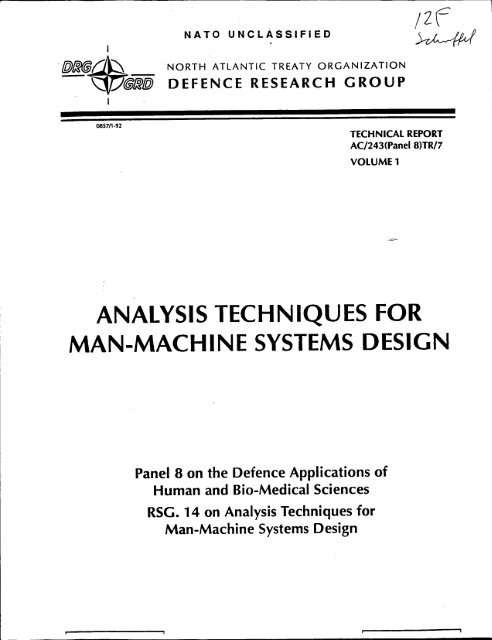
NATO UNCLASSIFIEDNORTH ATLANTIC TREATY ORGANIZATIONDEFENCE RESEARCH GROUP085711-92TECHNICAL REPORTAC/243(Panel 8)TR/7VOLUME 1ANALYSIS TECHNIQUES FORMAN-MACHINE SYSTEMS DESIGNPanel 8 on the Defence Applications ofHuman and Bio-Medical SciencesRSG. 14 on <strong>Analysis</strong> <strong>Techniques</strong> for<strong>Man</strong>-<strong>Machine</strong> <strong>Systems</strong> <strong>Design</strong>
ANALYSIS TECHNIQUES FORMAN-MACHINE SYSTEMS DESIGN-,..
N A T OU N C L A S S I F I E DREPORT DOCUMENTATION PAGE1. Recipient's Reference: 2. Further Reference:3. Originator's Reference: 4. Security Classification:AC/243(Panel 8)TR/7NATO UNCLASSIFIEDVOl. 1 5. Date: 6. Total Pages:31 JUL 92 104 O.7. Title (NU):ANALYSIS TECHNIQUES FOR MAN-MACHINE SYSTEM DESIGN8. Presented at:9. Author's/Editor's:Mr. 0. Beevis10. Autnor(s)/Editorfs) Address: 11. NATO Staff Point of Contact:DCIEMDefence Research SectionP.O. Box 2000 NATO Headquarters1133 Sheppart Ave. W. 8-1110 BrusselsDownsview, Ontario M3M 3B9BelgiumCanada(Not a Distribution Centre)12. Distribution Statement:This document is for official use only. It should be announcedand supplied only to NATO, Government Agencies of NATO nationsand their bona fide contractors. Distribution to other recipientsrequires authorization by the Head of the Defence ResearchSection.13. Keyworas/Oescriptors:MAN-MACHINE, HUMAN ENGINEERING, FUNCTION ALLOCATION, TASKANALYSIS, PERFORMANCE PREDICTION, COGNITIVE TASKS, P.8/RSG.1414. Abstract:Human engineering (known in some countries as human factors indesign or ergonomics) is a discipline by which data on humancapabilities and limitations are taken into account during theengineering design and development process. NATO AC/243(Panel8/RSG.14) completed a study of analysis techniques used for humanengineering. The RSG collected information on the of known humanengineering analysis techniques, compiled descriptions ofthirty-one existing techniques, reviewed them to identify theneed for new and improved techniques, reviewed the current stateof standardization of such techniques, and compiled examples offunctional decompositions of typical manned systems. The twovolumes of this report review the state-of-the-art of humanengineering analysis and fts relationship to systemsengineering.
CONSEIL DE L'ATLANTIQUE NORDNORTH ATLANTIC COUNCILN A T OU N C L A S S I F I E DORIGINAL: ENGLISH TECHNICAL REPORT31 July 1992 AC/243(Panel 8)TR/7Volume 1DEFENCE RESEARCH GROUPPANEL 8 ON THE DEFENCE APPLICATIONS OF HUMAN AND BIO-MEDICALSCIENCESTechnical Report on<strong>Analysis</strong> <strong>Techniques</strong> for <strong>Man</strong>-<strong>Machine</strong> Svstem <strong>Design</strong>This is Volume 1 of the technical report on <strong>Analysis</strong><strong>Techniques</strong> for <strong>Man</strong>-<strong>Machine</strong> System <strong>Design</strong>. The report wasprepared by RSG.14. The Executive Summary of this report("Yellow Pages") was also distributed under reference AC/243-N/359 dated 24 July 1992.(Signed) Dr. J. VERMORELDefence Research Sectioni~ ~ li ~ ilil l, ~~I j 11 il 111:'I i li d|t j;j : ill -1'.lNATO,1110 Brussels.0 ' 1 R 7 1 .7TN A T OU N C L A S S I F I E D
NATO UNCLASSIFIEDAC/243(Panel-8)TR/7 - u -Volume IThis page left blank intentionallyNATO UNCLASSIFIED
NATO UNCLASSIFIED- iii - AC/243(Panel-8)TR/7Volume IANALYSIS TECHNIQUES FOR MAN-MACHINE SYSTEM DESIGN0. EXECUTIVE SUMMARY"Because they do not take sufficient account of the limitations posed by man as wellas other factors of real life, many complex systems requiring a high degree of integration ofmany functions ... will simply break down under the exacting conditions of a real dynamicbattle .P. Naslin, Head, NATO Defence Research Section, 19830.1 SUMMARY OF THE STUDYi. Human engineering (known in some countries as human factors in design orergonomics) is a discipline by which data on human capabilities and limitations are taken intoaccount during the engineering design and development process. NATO AC1243 Panel-8/RSG.14 completed a study of analysis techniques used for human engineering. The RSGcollected information on the of use of known human engineering analysis techniques, compileddescriptions of thirty-one existing techniques, reviewed them to identify the need for new andimproved techniques, reviewed the current state of standardization of such techniques, andcompiled examples of functional decompositions of typical manned systems. Volume 1 of thisreport reviews the state-of-the-art of human engineering analysis and its relationship to systemsengineering. Volume 2 of this report contains reviews of thirty-one human engineering analysesand functional decompositions prepared to assist the application of human engineering inadvanced development projects.0.1.1 Backgroundii. Human engineering is an essential speciality within the systems engineering effortdirected at the integration of the human with hardware and software sub-systems throughanalysis, simulation, test and design. The analyses follow the same general pattern as those ofsystems engineering. They include: mission analysis, function analysis, function allocation, taskanalysis, and performance analysis.iii. As weapon systems become more sophisticated and pressure to reduce militarymanpower increases, there is a severe risk that the unique skills and abilities of humans may notbe exploited as effectively as they could be, thus degrading the potential performance of asystem. Therefore, programmes in several NATO nations are directed at human systemsintegration (HSI). Human engineering is an essential activity in those programmes. <strong>For</strong> example,in the USA, total manpower, personnel and training costs are estimated to be 50% of the lifecyclecosts of a weapon system. Thus life-cycle managers are interested in HSI from theviewpoint of reducing manpower requirements and personnel costs as well as obtaining a highlevel of system effectiveness. To assist in obtaining those goals, human engineering applicationsNATO UNCLASSIFIED
NATO UNCLASSIFIEDAC1243(Pane1-8)TRfl - iv -Volumne-1should start at the outset of a project and be updated throughout the development cycle, as withother engineering elements.iv. In 1984, a NATO DRG Panel 8 workshop reviewed "Applications of systemsergonomics to weapon system development" and made thirty-six recommendations to improvethe application of ergonomics (or human factors) technology, many of which were concernedwith human engineering (Merriman et al., 1984>. Subsequently an Exploratory Group, convenedto review the recommendations of the workshop, recommended the formation of a ResearchStudy Group to:* review the state of knowledge of analytical techniques* evaluate such analytical methods for their effectiveness, reliability and ease of use* stimulate co-operative efforts for improving existing methods, determining where newtechniques are needed, and for developing new techniques* recommend courses of action for improving the standardization of techniquesResearch Study Group (RSG) 14 was formed in October 1987 to work towards theseobjectives.miSC(an0.1.2 Survey of human engineering analysis techniquesv. RSG.14 compiled a list of twenty-four human engineering analysis techniques usedfor the analysis of Missions, Functions, Tasks, and Operator Performance. <strong>Man</strong>y of thesetechniques are similar to analytical techniques used in other systems engineering activities, andmight be expected to be in widespread use. The RSG surveyed the use of these techniques inthirty-three projects in seven countries (Chapter 2).havevi. It was found that the rate of application of the techniques was low and inconsistent, of stnalthough increasing. The application to NATO projects was extremely limited. The overall levelexisti.of knowledge of human engineering analysis techniques was very low also, and training coursesintegiin human engineering did not cover them. Therefore, the RSG decided to compile a guide to(ChaTthirty-one human engineering analysis techniques for use by project managers and engineers inthe NATO nations. Volume 2 Part 1 of this report represents the outcome of that work.I factorappro0.1.3 Review of human engineering analysis techniques develdevelvii. <strong>Analysis</strong> is a widely used approach in systems engineering and system design/development. This review covers analytical techniques used for human engineering (Chapter 3).The review does not deal with other human engineering techniques such as experimentation,modelling, man-in-the-loop simulation, rapid or virtual prototyping, test and evaluation, or fieldtrials, although the relationship of those techniques to analysis is discussed in the report. Thereview contains descriptions of the most widely used techniques for six major types of analysis,which, typically, are used in sequence (Fig. 0.1).viii. Modem approaches to design emphasize the functional aspects of systems. It hasbeen found difficult to do this without the benefit of reference to earlier applications. To supportthis, examples of system decompositions were also compiled and are reported in Volume 2 Part2. The material covers aircraft, ships, and army systems, and provide examples of sevendifferent approaches to functional decomposition.NATO UNCLASSIFIEDintegrallocastudiereviev- iv -
NATO UNCLASSIFIED-v - AC/243(Panel-8)TR/7Volume Imission 8scenapmolfunctionanalysesanalysis-functioninterface 8workspace-lallocation > akt designanalysisperformanceprediction .Figure 0.1: The sequence of human engineering analysesreviewed in the report0.1.4 Need for new techniquesix. Another aim of the RSG's work was to identifyhavethosea stronganalyticallink to currenttechniquesdevelopmentswhichin systems engincering,of structuredparticularlyanalysis andthe increasingdesign for softwareusedevelopment.existingInhumanadditionengineeringto compilinganalysisthe guidetechniques,tothe RSG reviewedintegratedhowwiththeothertechniquesengineeringmightactivities,beparticularly(Chapterthose4).of software systems engineeringx. Technological changes will affect: the human machine interface; the kind of humanfactors problems which may arise in operating or maintaining new systems or equipment: and theapproach to system design and development taken by designers and engineers. Several currentdevelopments in technology and in systems engineering will require correspondingdevelopments in human engineering techniques. These developments include:* the increasing importance of cognitive tasks in systems operation and maintenance* increasing use of computer based decision aids and knowledge-based systems* increasing use of computer simulation, rapid prototvping. and computer aided designas human engineering tools* increasing use of software engineering techniques and computer-aided softwareengineeringxi. As reviewed in Volume 1 Chapter 5, allintegratedof theseapproachdevelopmentsto systemsarguedevelopmentfor a morebased on theallocationanalysisofoffunctionssystem functions,to sub-systems,thethe analysisStudiesofwithinsub-systemthe contextinteractions,of systemsandengineering.feasibility0.1.5 Need for standardization of techniquesxii. National and NATO standards governingreviewedthe practiceas part ofofthehumanstudy.engineeringWithin individualwerecountries, the level of standardization of humanNATO UFNCLASSTIED
NATO UNCLASSIFIEDAC/243(Panel-8)TRfl - vi -Volume Iengineering analysis techniques is low. Within NATO it is extremely low, and inconsistent Thissituation is reviewed and recommendations for standardization are developed in Volume 1,Chapter 5.0.2 MAJOR RECOMMENDATIONSxiii. Based on the work outlined above, RSG.14 makes the followingrecommendations:* Panel-8 should support research and development of function allocation and taskanalysis techniques to deal with cognitive behaviour, as discussed in Chapters 3 and 4.* The DRG should collaborate with the NATO agencies responsible for standardizationto ensure the application of human engineering in NATO projects through thedevelopment of standards, specifications, and guidelines which identify andcdescribehuman engineering analysis techniques, the latter based on Volume 2 of this report, asdiscussed in Chapter 5.* The DRG should collaborate with the NAGs to explore how current technologicaldevelopments can be used to integrate the human, software, and hardware aspects ofproject development in such a way that human engineering becomes an inseparable partof the design/development process based on the use of computer software, asdiscussed in Chapter 3.0.3 MILITARY IMPLICATIONSxiv. The following are the military implications of the work of the RSG:* The effectiveness of a total system depends on the performance of the humancomponents for planning, decision making, supervision, control, and maintenance.* <strong>Man</strong>power is an increasingly limited and expensive resource, and must be utilized tothe most effective extent possible.* The human components have a large influence on the life cycle costs, effectiveness,reliability, and readiness of weapon systems.* Effective human sub-system utilization is obtained through the application of humanengineering throughout the entire weapon system development process, includingupgrading and updating.* The human engineering analysis techniques described in this report are essential to thatprocess and should be used in future development projects. Standardization of theapproach to human engineering within NATO will facilitate the use of thosetechniques.NATO UNCLASSIFIED- vi -
NATO UNCLASSIFIED- vii - AC/243(Panel-8)TR/7Volume I0.4 REFERENCES1. Merriman, S.C., Muckler, F., Howells, H., Olive, B.R., & Beevis, D. (1984).Applications of systems ergonomics to weapon system development. (NATO DS/A/DR(84)408). Brussels: NATO Defence Research Group.2. Naslin, P. (1983). The human as a limiting element in military systems. In: Proceedings ofthe 24th DRG Seminar (Closing address). DS/A/DR(83) 170. Brussels: NATO DefenceResearch Group.NATO'UNCLASSIFIED
NATO UNCLASSIFIEDAC/243(Panel-8)TR/7 - viii -.Volume IOUTLINE OF CHAPTERSParagraph No.CHAPTER 1 -INTRODUCTION TO SYSTEMS DESIGN ANDHUMAN ENGINEERING ANALYSES 1- 71.1 INTRODUCTION1.2 THE OVERALL CONCEPT: THE SYSTEMS DEVELOPMENT 8 -15PROCESS1.3 HUMAN ENGINEERING TECHNIQUES 16 - 19a-1.4 TERMS OF REFERENCE 20 - 221.5 REFERENCESCHAPTER 2 - SURVEY AND REVIEW OF ANALYSIS TECHNIQUES2.1 SURVEY OF USE OF HUMAN ENGINEERING ANALYSIS 23 - 32TECHNIQUES2.2 REVIEW OF HUMAN ENGINEERING ANALYSIS TECHNIQUES 33 - 362.3 OVERVIEW OF HUMAN ENGINEERING ANALYSIS TECHNIQUES 372.3.1 Mission and Scenario <strong>Analysis</strong> 382.3.2 Functional <strong>Analysis</strong> 392.3.3 Function Allocation <strong>Analysis</strong> 402.3.4 Task <strong>Analysis</strong> 412.3.5 Performance Prediction 422.3.6 Interface and Workspace <strong>Design</strong> 432.3.7 Summary 442.4 APPLICABILITY OF TECHNIQUES IN SYSTEM LIFE-CYCLE 45 - 47PHASES2.5 REFERENCESCHAPTER 3 -HUMAN ENGINEERING ANALYSIS TECHNIQUES3.1 INTRODUCTION 483.2 CHARACTERISTICS OF THE TECHNIQUESNATO UNCLASSIFIED- viii -
NATO UNCLASSIFIED- ix - AC/243(Panel-8)TR/7Volume 13.2.1 What the techniques do 49 - 503.2.2 Inputs/outputs of the techniques 513.2.3 When to use 52 - 543.2.4 Related techniques 55 -593.2.5 Resources required 60 - 623.2.6 Advantages/disadvantages63 - 643.2.7 Relative contribution 65 - 663.2.8 Applications67-683.2.9 Quality assurance considerations 69 - 723.2.10 Relationship to system performance requirements 73 - 753.3 CONCLUSIONS FROM REVIEW OF HUMAN ENGINEERING 76 - 82ANALYSIS TECHNIQUES3.4 REFERENCESCHAPTER 4 - REVIEW OF NEED FOR NEW OR IMPROVED TECHNIQUES4.1 INTRODUCTION4.2 CHANGES IN HUMAN TASKS4.2.1 Increase in cognitive tasks 84 - 874.2.2 Increasing use of decision aids and knowledge-based systems 88 - 904.3 NEW DEVELOPMENTS IN SYSTEM AND SOFTWARE ENGINEERING4.3.1 Computer-supported structured analysis/design methods 91 - 934.3.2 Rapid Prototyping and User Interface <strong>Man</strong>agement <strong>Systems</strong> 94 - 964.4 NEED FOR INTEGRATION OF SYSTEM DEVELOPMENT ACTIVITIES4.4.1 Increased emphasis on trade-off studies 97 - 984.4.2 User centred system design 99-1024.4.3 Integration of system development activities 103 - 1084.5 CONCLUSIONS4.6 RECOMMENDATIONS4.7 REFERENCESCHAPTER 5 - RECOMMENDATIONS FOR STANDARDIZATION5.1 INTRODUCTION83109 - 114115 - 1165.2 STATE OF STANDARDIZATION OF HUMAN ENGINEERING 118 - 119ANALYSIS TECHNIQUES117NATO UNCLASSIFIED- x -
NATO UNCLASSIFIEDAC/243(Panel-8)TR[7 - x -Volume I5.2.1 Human engineering standardization 1205.2.2 The status of human engineering analytical techniques 1215.2.3 The description of analytical techniques within requirements 122 - 1235.2.4 Use of application-specific and commercial standards 124 - 1255.2.5 Growing use of computer-based analysis techniques 1265.3 PROBLEMS AND THE NEED FOR STANDARDIZATION OF 127ANALYTICAL TECHNIQUES5.3.1 Lack of requirements documents addressing analysis 128 - 1305.3.2 Differences in terminology 131 - 1325.3.3 Lack of documents tailored to specific users 1335.4 AN APPROACH TO THE DEVELOPMENT OF NATO REQUIREMENTSDOCUMENTS5.4.1 An approach for a standard 1345.4.2 An approach for specifications and guides 135 - 1365.4.3 An approach for computer based system development 1375.4.4 Approach summary 1385.5 CONCLUSIONS 1395.6 RECOMMENDATIONS 1405.7 REFERENCESAPPENDIX A TO CHAPTER 5: Human engineering requirements documentsin use in member nationsCHAPTER 6 -CONCLUSIONS AND RECOMMENDATIONS6.1 INTRODUCrION 1416.2 AVAILABLE HUMAN ENGINEERING ANALYSIS TECHNIQUES 142 - 1466.3 THE NEED FOR NEW OR IMPROVED TECHNIQUES 147 - 1516.4 THE NEED FOR STANDARDIZATION 152- 1546.5 RECOMMENDATIONS 155 - 156NATO UNCLASSIFIED.7
NATO UNCLASSIFIED- xi - AC/243(Panel-8)TRn7Volume 1LIST OF FIGURESCHAPTER 1Figure 1.1 Three interacting sets of system resources 1Figure 1.2 The human-machine system 2Figure 1.3 Factors influencing a design concept 3Figure 1.4 Factors found to influence flight safety and operational 4effectivenessFigure 1.5 The system development process 6Figure 1.6 Hypothetical relationship between conditions to measure human- 7machine performance and control of factors affecting performanceFigure 1.7 Some factors causing operational degradation 8Figure 1.8 System and function viewpoints on development 10Figure 1.9 The systems ergonomics approach 11CHAPTER 2Figure 2.1 Stages of human engineering analysis 15Figure 2.2 Overall number of applications of 24 human engineering analysis 17techniques in five phases in 33 projects 17Figure 2.3 The sequence of human engineering analyses reviewed in this 19reportFigure 2.4 The systems engineering process 20Figure 2.5 Human engineering activities associated with systems engineering 21Figure 2.6 The contribution of task analysis to system development 23Figure 2.7 Relationship between task analysis, performance prediction and 24interface and workspace designFigure 2.8 Flow of information associated with interface and workspace 25Figure 2.9 Flow of information generated by the six stages of humandesignI26engineering analysisFigure 2.10 Products of the system life cycle phases 28CHAPTER 3Figure 3.1 Information generated by the sequence of human engineering 36analysisFigure 3.2 Different patterns of design development 37Figure 3.3 Number of quality assurance criteria used for human engineering 41analyses reviewed in Volume 2Figure 3.4 Principal activities required to evaluate systems effectiveness 42CHAPTER 4Figure 4.1 Human capability demands 47NATO UNCLASSIFIED
NATO UNCLAS S IFIEDAC/243(Panel-8)TR[7 - xii -Volume ICHAPTER 1LIST OF TABLESTable 1.1 Human factors/ergonomics steps during manned systems design 9CHAPTER 2Table 2.1 Mean rate of use of different categories of analysis technique, in 16five project phases, in 33 projectsTable 2.2 Development life-cycle phases used in different nations 27Table 2.3 Applicability of available human engineering analysis techniques 30 - 31per phase of the design processCHAPTER 3Table 3.1 Links between types of analysis and system performance 44-r 45CHAPTER 4Table 4.1 Skill, rule, and knowledge based behaviour 48CHAPTER 5Table 5.1 Requirements documents which reference analytical techniques 60Table 5.2 Human engineering techniques referenced and described in 61standards, specifications and guidesTable 5.3 Allied Naval Engineering Publications (ANEPs) concerning human 62factors in ship designTable 5.4 Number of analysis techniques referenced and described 64Appendix A Human engineering requirements documents in use in member 69 - 73to Chapter 5 nationsNATO UNCLASSIFIED-Xli -
NATO UNCLAS SIFTED1.-AC1243(Panel-8)TrRnVolume ICHAPTER 1INTRODUCTION TO SYSTEMS DESIGN ANDHUMAN ENGINEERING ANALYSES"We have to design equipment to take full advantage of the capabilities of our personneland we have to design equipment that will not overload, confuse or degrade personnelperformance in achieving mission objectives ... We have to reduce design-induced humanerror which is so costly a component of accidents and operational failures. We have to planfor the wise and judicious use of the limited personnel and skill levels available to us bvoptimizing manpower requirement, and through more effective use of automation andexpert systems. We have to design with greater efficiency and productivity inDrder toreduce costs to our services and to our nations."Rear Admiral R. Horne. USN, 19901.1 INTRODUCTION1. <strong>For</strong> a long time, humans have manufactured devices. equipment. and systems whichpermit the accomplishment of activities, whether work or combat, to satisfv increasinglydemanding and complex objectives with increasing effectiveness and reliability. Up to the end ofthe 19th century, almost all manufactured items were made to measure by craftsmen who tailoredthe product to the user. The development of industrialization and the mass production of objectshas forced manufacturers to make identical items for effective use bv a large number ofindividuals. Today, the achievement of a specific objective often requires the efforts of severalgroups of individuals using several complex machines, some automatic, in a formal organization.Today, it is not possible to manufacture complex objects such as weapons without consideringthem as systems, defined as "the ensemble of.elements capable of achieving a goal or a missionwith autonomy" (Dictionaire Robert).( re s o u uresorcnd social envrnenFigure 1.1:Three interacting sets of system resourcesN A TO TTMCT. ASS TFTED
NATO UNCLASSIFTEDAC/243(Panel-8)=RJ1 - 2 -Volume-i2. The effectiveness of mission accomplishment depends upon the exploitation of thevarious system resources, i.e., people, material, software, and orgation in a physical andsocial environmenL (Fig. 1.1). These resources provide the system elements. or sub-systems.The human resource is defined by the personnel who are available, their knowiedge and skills,and their characteristics (manpower, personnel, and training). Successful exploitation or thearsystem resources depends not only on their capability (sub-system performance) but on thequalitv of the interactions between them (sub-system compatibility, and sub-system S(communication). That is why designers must research the best interactions between the elements P.and combine them into an effective system, i e., they must design an integrated system. Theninteractions which the designer must consider include those between the selection and training ofdthe system operators and maintainers and the complexity of the hardware and software designCh(Fig. 1.2).< aSllOperatingMaintenancepersonnel i personnelSoftwareFigure 1.2:The human-machine system3. While taking the human system components into account, the designer mustremember that there are important variations from one human to another. whetheranthrotometric, physiological. psychological. or cultural. These human variations interact withone another, and, for any one individual, some characteristics change over time. In addition.human system elements may require protection from their working environment. The humansub-system factors which must be considered in the development of weapon systems comprise:* Human factors and cognitive psychological information which defines the capability ofoperators and maintainers to do mental work, the nature and content of information forpresentation, and the needs for training and practice.* Physiological and biodynamic information which defines the capability of operators andmaintainers to do physical work, their body positions and postures, the forces exertedon controls, the location of the components of the human-machine interface, the formand size of those components, for example, and requirements for physical protection.*Anthropometry information which defines human physical dimensions. the dimensionsof the work space and the location of controls and displays.Information from the foregoing disciplines which determines manpower requirements,the length of work period, and needs for and means of protection against environmentalconditons and safety and health hazards.NATO UNCLASSIFTED
NATO UNCLASSIFIED-3 - AC1243(Panel-8WR17Volume l4. This information must be considered in terms of the variance which it represents,and viewed in terms of the functions and tasks the operators must accomplish. In this context,the design problem can be expressed as follows: ensure that manufactured hardware andsoftware can be used by, and provide protection for, the maximum number of individuals from apopulation which is quite varied. That is why, the more complex products become, the more it isnecessary to use special methods to take human factors into account in the design anddevelopment of those products. This is the main task of human engineering (known in somecountries as human factors in design or ergonomics) which involves consideration of the relevanthuman factors issues, the methods for analysis such as those described herein, and the meansand the scheduling of effort to integrate the results in design and development of hardware andsoftware.5. Human engineering should be involved in the search for solutions which permit theoptimal use of products (satisfaction of the need) by potential users (the human resource) whilerespecting the entirety of the latter in physical, psychological and moral terms. The benefits ofhuman engineering can be very significant. Among them are reduced errors and reduction ofuncertainty about how the system will operate, reduced system costs (both acquisition and lifecycle),reduced training costs, and manpower reduction compared to existing systems. <strong>For</strong>example, a US Navy Research Advisory Committee estimated that the proper application ofhuman engineering can result in a 20% reduction in manpower in Navy surface ships. Efforts inprogress in other navies provide further evidence of the gains which can be achieved by effectiveintegration of humans and machines. The German, Norwegian and Netherlands navies all haveactive programmes to produce new ships with extensive attention to human-machine interfaces.The Netherlands Walrus II submarine has a crew size of 50, reduced from 70 persons in aprevious, similar Zwaardvis class. It will have no decrease in capabilities. but some increase intraining requirements. Similar results are being pursued in the new "M-Frigate" which has acomplement of 156 compared to 190 in the older ST class. Considerable use is being made ofautomated monitoring and control systems. computerized displays, extensive man-machinedesign and testing, and on-board training and cross-training.( Mlssloneed ) | (umnanreoc)k J < ontradeofsenvironmentFigure 1.3: Factors Influencing a design conceptXr A TT XT T 1-TAvvTTTF)F
NATO UNCLASSIFTEDAC/243(Panei-8)TR17Volumei-- 4 -6. The human engineering perspective is based on the concept of the system and theintegration of the human in it. The role of human engineering specialists is to give engineers themeans of choosing technical solutions necessary for the production of equipment and systems.The technical solutions chosen to implement a system will be the result of a compromise betweendifferent requirements, some of which may conflict. This compromise includes consideration oftechnical and financial possibilities and schedules (Fig. 1.3), and can be determined only fromknowledge of the system mission, which permits the identification of the necessary functions,and by the same means, the operator's task demands.cU.,7. The integration of the human subsystem involves many human factors h:considerations. It must be remembered that although adaptability and capacity for decisionTmaking make the human an irreplaceable system component. the human can be a weak link in thesystem due to variability in performance over time. Because of this. and because of the wideErange of factors which affect human performance, human engineering cannot address all the risksof poor performance, incidents or accidents. <strong>For</strong> example, Figure 1.4 presents an Ishikawa(cause factor) diagram of factors rated by aircrew as influencing their flight safety and operationaleffectiveness. These factors include aircraft operations. training, personnel and organization. aswell as human engineering issues.Human Engineering Aircraft Operations Training Factorsaircraft reliability \ multiple operational roles \ spatal disorientation trainingaircraft capability compared \ available flying time. * centrduge/G-stress trainingto pilot capability air displays and * aeromedical trainingspatial disorientation non-operational flying * aircraft skill requirementsstandards of graduating pilots\the HUDaircraft systems \ airmanshipchemical defence equipment* supervision of flying andexperience of supervisorsG-protection system*oxygen systemtraining of supervisors\other life support equipment\ \ \Flight Safety\ \ Xand/ pilt experience /Operational/plot attrition/[Effectiveness/career policies /lyng related woIrkoadfinancial situation of pilots* impact of non-flying duties and* family pressures on pilots & famiiy non-flying related workloadand social effects of postings . manning levels in squadronsofficer development* time available to shoot the breezerequirementsan Hyingthe a programme to address A available study timepilot attrition / long-term fatiguePersonnel andWorkload in SquadronsTI Organization , I SFigure 1.4: Factors found to Influence flight safety and operationaleffectiveness (after Davidson et al., 1991)NATO UNCLASSIFIED
NATO UNCLASSIFIED5 - AC/243(Panet-8)TRf7Volume I1.2 THE OVERALL CONCEPT: THE SYSTEMS DEVELOPMENTPROCESS8. In the development of military systems and equipment, human factors (humanengineering, manpower, personnel training, system safety and health hazards) must be includedin the larger concept of the life cycle of the product. Several project management programmeshave been developed for the integration of human factors with other systems design factors.Typical programmes include MANPRINT, developed by the US Army, IMPACT, developed bythe US Air <strong>For</strong>ce, and the human-systems integration programme being developed by the USDepartment of Defense. Other nations within NATO, including France, FRG, and UK, areadopting simila approaches which are being studied by NATO AC/243 Panel 8 RSG 21. Thesemanagement programmes address manpower, personnel, training, safety and health hazards, andhuman engineering, to improve system performance, reduce human error, and minimize relatedcosts (Booher, 1989).9. Recently the systems development process has also expanded to include disciplinessuch as Concurrent Engineering and Total Quality <strong>Man</strong>agement. Concurrent Engineering focuseson the iterative character of the design process. The aim is to have designers consider the systemthroughout its life cycle, from project initiation to system disposal. taking into account allsystems elements with regard to operation, maintenance. production and logistic support, as wellas quality, costs schedules and user requirements (Winner et al., 1988). Human engineering cansupport this approach because the study of system operation and maintenance issues is central tohuman engineering activities. Total Quality <strong>Man</strong>agement (TQM) is an approach which seeks tominimize the variance in the quality of products through gearing the attitudes of personnelinvolved in the design and production process towards quality consciousness. Improved designtechniques are conceived as results of these attitude changes (Demming, 1982). Humanengineering can support the TQM approach by helping to identify the characteristics of the usersand their requirements for systems and equipment. Human engineering can also contribute toTQM by identifying those features of human operator performance which contribute to variancein the system product or output, for example, reaction times, the correctness of procedures,correctness of operator decisions, or magnitude of operator errors.10. The starting point of the systems development process for both equipment andpersonnel is the identification of operational needs of the system to be designed. Svstemengineering transforms the operational need into a system description by following a series ofsteps involving analysis, synthesis, trade-off studies. and simulation and test. Although systemsengineering texts do not agree on terminology, the essential steps (from Chambers. 1986) are:* mission requirements analysis* functional analysis* function allocation* synthesis of a system concept* logistic engineering* life cycle cost analysis* optimization (including trade-off studies. cost effectiveness studies. and effectivenessmodelling)* generation of specifications11. The systems development process seldom starts from an operational requirement todevelop a system description by analysis alone. Usually, some concept of the system exists, forexample, as the idea of an attack aircraft, or a sea-based surveillance svstem. or an existingNATO UNCLASSIFIE-D
NATO UNCLASSIFIED-143tPanei-8)Tw7n3lume L6 -,stem concept which can be upgraded or improved. As the systems engineers decompose the'stem requirements and synthesize the system specification, they repeatedly check the results ofeir analyses against their original concept, and modify the latter where necessary. A system (orproduct) exists in different forms at different stages of development (need. virtual, real andperational - Papin, 1992). The transition from one stage to another is a function of theevelopment process. That process involves different activities (analysis. specification, design,ianufacture, evaluation, and use) (Fig. 1.5). The goal of this report is to review the techniquessed for the analysis of human-machine systems. from mission requirements analysis through to.e generation of specifications.System stateNeed -Conceptuals y s t e .. m illl,~M~vHardware andsoftwareNATO Phased Armaments Programming <strong>Systems</strong> (PAPS) Project Phases.<strong>Design</strong>1 2 3 4 5 6 7.................... . .SpecicatiOication,& evelooment<strong>Man</strong>ufacturconditiooperatioapproacimissionexpeinmcontroll(ardflcialHi03:<strong>Man</strong>ned systeml123Q&56 7LepoaXFigure 1.5: The system development processexperi12. Engineers and human engineering specialists have had a growing interest in practicaccounting for human performance in system effectiveness. Both groups of specialists haveexpdeveloped tools for predicting human-machine performance. Engineers supply disciplines suchinvolvas cybernetics, control theory and work study, while human engineering specialists use specificthedesign methods, information theory, operational research and, in particular, test and evaluationthe rigmethods, to account for human factors and human variance. The key to the involvement of thehuman engineering in the systems development process is the description of human performanceschadeternin ways which are compatible with the other engineering activities.l3. Approaches to describing human performance include real world observations field oSnldstudies, man-in-the-loop-simulator studies. laboratory experiment. and pure computer-simulationstudies including simple representations of human behaviour. The first two approaches, whichare relevant to both new and old systems, have the common drawback that they fail to considerdesigiand control an unknown number of variable factors which affect behaviour. Obviously, theconceFitN A T OI
NATO UNCLASSIFIED7 - AC1243(Panel-8)TRflVolume Iconditions in which real world observations and field studies are made are very close to actualoperations. This is true to a lesser extent for simulator studies (see Fig.1.6). Generally, theseapproaches (real world observations and field trials) are suited to description and analysis of themission, incidents and accidents and the operator's activities. Simulator and laboratoryexperiments are aimed at prediction of performance for routine and emergency conditions undercontrolled environmental conditions. but have the drawback of doubtful generalization from theardficial test conditions to reality.High Fidelity with the real world LowObservations andmeasurements in - Games -*othereal worldX.~..........- Field studies Monte-Carlo3 an-in-the-ioop simulationsa: . simulationsRaoid-- Ra- ,prototyping-,a*-.. Mathematicalmodels-o*- Laboratory experiments -N-. l Psychological tests -OLow HighFigure 1.6: Hypothetical relationship between conditions to measure humanmachineperformance and control of factors affecting performance.(after Chapanis & Van Cott. 1972)14. From a methodological viewpoint there would be an optimum in simulatorexperiments, -which have sufficient representation of the real world to generalize results forpractical conditions and are sufficiently controlled to allow the interpretation of results. This typeof experiment offers the opportunity to judge human variance in performance relative to thevariance due to the use of alternative pieces of equipment, procedures, etc. Rapid prototypinginvolves the use of representations of human-machine interfaces in quasi-realistic scenarios. Atthe right hand side of Figure 1.6, representing the extreme of abstraction from the real world, arethe pure computer-simulation studies which model human behaviour in a deterministic orstochastic way. Simulations using mathematical models may incorporate human characteristics,including a certain randomness in performance. In essence, however, models remaindeterministic/stochastic and can reveal "unpredicted" interactions of behaviour with equipment toonlv a limited extent. Human performance models have been reviewed bv another ResearchStudy Group of NATO DRG Panel 8 (see McMillan et al., 1989; 1991).15. From the svstems engineering viewpoint, however, most activities in systemsdesign/development involve analvsis and synthesis of a design solution. Therefore, this reportconcentrates on human engineering analysis techniques. Those analyses can identify the humanNATO U. NCLA-SSIFTED
NATO UJNCLASS IFTEDACt243(Panei-8)TRW7- 8 -Volume 1tasks which may require close examination by field trials, simulation, experiments ormathematical modelling. As reported by Lovesey (Fig. 1.7), the estimates of a system'seffectiveness are degraded successively from concept through field trials and initial introductioninto service to routine and wartime operations. Appropriate use of human engineering in theoverall design of a system will help to produce designs that are more compatible with thecapabilities and limitations of personnel, thereby reducing the inevitable degradation inperformance from system concept to the combat environment.TMACHINE£ .. .. /.FACTORS> 81"A f s °.-u cJ r~~~w~gJ0 e tc °1 .tWLow|-coand ptoet cntHUMANSore WM. fatigue. sleepls iLow [ FACTORS /PROGRESSION OF SYSTEM DEVELOPMENT AND USEFigure 1.7: Some factors causing operational degradation (after Lovesey, 1987)1.3 HUMAN ENGINEER{ING TECHNIQUES16. Table 1.1 gives an overview of the main human engineering design steps in thesystems development process (U.S. NAVSEA, 1990). These parallel the essentiai steps insystems engineering. When a system or equipment is being modified, without this beingclassified as a mid-life improvement, some of the early steps are not carried out fully, or may beomitted. The sequence of human engineering analyses follows the same general pattern assystems engineering, including: mission analysis, function analysis, function allocation, taskanalysis, and performance prediction. This human engineering process was recommended foradoption in the NATO Land Operations Study (NATO DRG, 1981). The sequence of analyseshas been formalize d in NATO STANAG 3994 Al (Application of human engineering to advancedaircraft systems) (NATO MAS, 1991). Some of the steps associated with human engineeringanalyses have been documented by NATO Naval Armaments Group Information ExchangeGroup 6, Sub-Group (IEG-6, 199 1).17. As noted in para. 1 1, a concept of the system may well have been established prior toany analysis being undertaken. Because of this, many designers and engineers have difficultyunderstanding the need for analysing systems from a functional viewpoint. The importance ofsuch an approachis that it permits engineers and designers to look at the system concept in newways, by identifying the functions which must be performed, rather than by identifying theNATO RNCSASSIFED
NATO UNCLASSIFIED9 - AC1243(Panel-8)=R!7Volume ITable 1.1: Human tactorsiergonomics steps during manned systems design(after Pearce, 1990)* Evaluation of lessons learned" data* Identification of prerequisites* Determination of operational requirements* Mission analysis* Function analysis* <strong>Analysis</strong> of available operator/maintainer capabilities<strong>Techniques</strong>* Function allocation reviewed inthis report* Task analysis* <strong>Man</strong>-machine interface requirements analysis* Workload analysis* Identification of manpower requirements* Verification of concordance with prerequisites* Identification of training requirements* Workspace/workplace requirements analysis and determinationof workspacetworkplace design parameters* Environmental requirements analysis and determination ofenvironmental design parameters* <strong>Design</strong> of man-machine interfaces and job aids* Implementation of habitability requirements* <strong>Design</strong> of training programme* Evaluation of operability/maintainability/supportability* Preparation of "lessons learned"N!/
NATO UNCLASSIFIEDIAC243(Panei-8)=Volume-- 10-ispriualsub-systems which may be required. This change of viewpoint (see Fig. 1.8) is particularlyimportant if novel system designs are to be developed, for example, a tank with reducedmanning, or a system with improved maintenance. If a function-oriented view is not taken. thendevelopment from one generation of system to the next will be evolutionary, rather thanrevolutionary. Even if revolutionary changes are not required. the quality of design is improvedby taking a functional viewpointrequirement& constraintviewtfuture missionrequirements andrequirementstem conorientedviewsystem functionsimproed/narefuctonlcocetsystemorientedviewFigure 1.8:identity existingsubsystems &comoonentseveiop concepts ofuture subsystemsSystem and function viewpoints on development(after Haberfellner, 1978)18. The design/development process should be iterative (Dbring, 1983; Meister, 1985).IThis means that mission and function analysis, allocation of functions. and determination oftasks and interface requirements are repeated several times in the course of synthesis, analysis ordesign of the system (see Fig. 1.9). By analyzing the mission. system functions are determined.The analysis of system functions leads to functional requirements which are the basis forallocating the functions to humans and machines. The detailed function analysis identifies thetask performance required of the operator and the required machine processes. Finally theanalvsis of the operator tasks and the machine processes gives the data for work station design.work environment design, workload evaluation, and personnel selection and training.19. Despite the similarity in aims and procedure, human engineering analyses are notalwavs conducted concurrently with other systems engineering activities. In current practice. thesystem concept is often developed well beyond the point of function allocation before humanfactors issues are considered-This makes the human engineering function allocation analyses oflittle value. Yet the increasing levels of automation in current systems make it more important thatthe roles and functions of the human operators been analyzed in detail. One of the aims of thisreport is to highlight those human engineering activities and analytical techniques which have astrong link to current developments in systems engineering, particularly the increasing use ofstructured analysis and design techniques for software development.NATO UNCLASSIFD
NATO UNTCLASSIFTEDI I -ACP243(PaneI-8)1TgVolume IDeslgn and development activityInformnatiOn generated ; ,scnai 410 , 4- hua reure , srworkinsnioacentasklnas* , Itofhnt.rtaceiPoad evaluamon.Ad . -. - -display and controlFlu.i. n h u nction omisa1.4 TERMS OF REFERENCE20. Despite a growing interest in the application of human engineering, there are fewguides for either project managers or practitioners. In his report on "A Survey into the Responseto a Proposal for the Distribution of Human Engineering Data to NATO Countries." H~ardy(1975) recommended that "action be instigated to produce suitable (human engineering)handbooks" to help engineers and designers become familiar with human engineering principlesand data. In a more thorough review of "Applications of <strong>Systems</strong> Ergonomics to WeaponSystem Development" a NATO DRO Panel 8 workshop concluded that existing humanengineering techniques were not easy to use, and were not being used widely (Merriman et al.,1984).21. Subsequently Research Study Group 14 was formed with the following terms ofreference:(a) To review the state of knowledge of analytical techniques for Mission <strong>Analysis</strong>.Function <strong>Analysis</strong>, Function Allocation, Task <strong>Analysis</strong> and Performance Predictionthat are appropriate to the design of new weapon systems.(b) To evaluate such analytical methods for their effectiveness, reliability and ease ofuse.(c) To stimulate co-operative efforts for improving existing methods, for determiningareas where new techniques are needed, and for developing new techniques wherenecessary.1 TERMST O FE D
NAT O UNCLAS SIFTEDAC/3(Panel-8 7 -12-(d) To recommend courses of action for improving the standardization of techniques forhuman-machine system design.22. The RSG conducted a survey among major contractors and human factors specialistsin each of the member nations, to sample the rate of use of "standard" human engineeringanalysis techniques and user experience with them. Following this survey, the RSG confirmedthe following plan of work:* Review existing analysis techniques, and the use made of them, and their compatibilitywith engineering processes.* Review the limitations of existing techniques. and the need for new or improvedtechniques.* Prepare examples to aid analysts in compiling system functions.* Compile a directory of experienced analysts who can act as resource persons.* Prepare recommendations for the standardization of human engineerinuIergonomicsanalysis techniques.* Produce a report based on the above work.1.5 REFERENCES1. Booher H.R. (Ed) (1990). MANPRINT: An aprroach to systems intenration. New York:Van Nostrand Reinhold.2. Chambers, G.J. (1986). The system engineering process: a technical bibliography. IEEETransacns on DSMC. (5) 712 - 722.3. Chapanis, A. & Van Cott, H.P. (1972). Human engineering tests and evaluations. In: H.P.Van Cott & R.G. Kincade (Eds.), Htuman entineeri i- iuide to equipment design. Chapter15. New York: Witley-Interscience.4. Davidson. R.A., Beevis, D., Buick, F., Donati. A.L.M.. Kantor, L., Bannister, S.H.R.,Brook. E.A., Rochefort, J.A.P., & Turner, J.R. (1991). Human factors in the CF- 18 pilotenvironment (Report 91-11). Toronto: DCIEM.5.Defense <strong>Systems</strong> <strong>Man</strong>agement College (1990). <strong>Systems</strong> endineerin- mana ement 2uide.Washington, D.C.: U.S. Government Printing Office.6. Demming, W.E. (1982). qualit. oroductwitv and competitive position. Cambridge MA:Massachusetts Institute of Technogyn Advanced Engineering Study.7. Doring, B. (1983). <strong>Systems</strong> ergonomics, an approach for developing well-balanced, costeffectiveman-machine systems. In: The human as a limiting element in military systems.Vo. 1. (NATO DRG DS/A/DR (83)170), Brussels: NATO Defence Research Group.8. Haberfellner, R. (1978). Lebebsphasen eines systems. In: W.F. Daenzer (Ed.), SvstemsIenginen.g Koeln: Peter Hanstein Verlag Gmbh.9. Hardy, (1975). A survey into the response to a proposal for the distribution of humanengineering data to NATO countries. (Panel VIII EG Report), Brussels: NATO DefenceResearch Group.NATO UNCLA S SIFTED
NATO UNCLASSIFTED- 13 - AC/243(Panel-8)TR/7Volume l10. Home, R.Adm. R. (1990). Address to NATO AC/243 Panel-8JRSG.14. Washington D.C.:U.S. Naval Sea <strong>Systems</strong> Command.l1. Lovesey, EJ. (1987). An attempt to quantify some factors that affect the operationaleffectiveness of a system. Applied Ergonomics 18 (4), pp 305 - 310.12. McMillan, G.R., Beevis. D., Salas, E., Strub. M.H., Sutton. R. & van Breda. L. (Eds)(1989). Applications of human performance models to system design. New York: Plenum.Defense Research Series Vol.2.13. McMillan, G.R., Beevis. D., Salas, E., Stein, W., Strub, M.H., Sutton, R., & van Breda.L. (1991). A directory of human performance models for system design. (Report AC/243(Panel-8) TRt1), Brusseis: NATO Defence Research Group.14. Meister, D. (1985). Behavioral analysis and measurement methods. New York: John Wiley& Sons.15. Merriman, S.C., Muckler, F., Howells, H., Olive, B.R., & Beevis, D. (1984).Applications of systems ergonomics to weapon system development. (NATODS/A/DR(84)408). Brussels: NATO Defence Research Group.16. NATO DRG (1981). LO/2000: Implications of new technologies for land operations in theNATO central region. (NATO AC/243-Dn63: AC/243 (LTSS)D/30F). BrussedM: NATODefence Research Group.17. NATO MAS (1991). Application of human engineering to advanced aircraft svstems.(STANAG 3994 Al (Edition i)), Brussels: NATO Militarv Agency for Standardization.18. Papin, J.P. (1992). L'ergonomie de conception d'un produit. Anger, France: Direction desArmaments Terrestres. Service Facteurs Humains.19. Pearce, F. (1990). <strong>Man</strong>ned systems engineering in U.S. NAVSEA. Presentation to 7thmeeting of NATO AC/243 Panel-8/RSG.14. Washington D.C.: U.S. Naval Sea <strong>Systems</strong>Command.20. Winner, R.I., Pennell, J.P., Bertrand, H.E.. & Slusarczuk. M.M.G. (1988). The role ofconcurrent eniineerinc in weapon systems acquisition. (IDA R-338). Washington D.C..Institute for Defense <strong>Analysis</strong>.NATUNCLASSTFTED'
NATO UNCLASSIFIEDACP-43gne-)TRj714 -This page left blank intentionallyM A T(to u-N-C-1.A &M EI)rE
NATO UNCLASSIFIED-15- AC/243(Panel-8)TRnVolume ISURVEY AND REVIEWCHAPTER 2OF ANALYSIS TECHNIQUES2.1 SURVEY OF USE OF HUMAN ENGINEERING ANALYSISTECHNIQUES23. To conduct the survey, human engineering analyses techniques identified inavailable human engineering guides and regulatory documents were categorized into one of fivesequential stages of analysis. These stages were: Mission <strong>Analysis</strong>, Function <strong>Analysis</strong>, FunctionAllocation, Task <strong>Analysis</strong>, and Performance Prediction (Fig. 2.1). Twenty-four techniquesdescribed in human engineering guides were identified and assigned to one of these stages ofanalysis. The project phases used by the RSG member nations were identified itd used todevelop a common, five-phase, project development cycle. The phases were: <strong>Analysis</strong> ofExisting <strong>Systems</strong>, Planning New <strong>Systems</strong>, Preliminary <strong>Design</strong>, <strong>Design</strong>, and Test & Evaluation.The five categories (stages) of human engineering analvsis technique and the five project phaseswere used to create an applications matrix (Table 2.1). A questionnaire was issued to companiesand organizations known to employ human factors specialists in the seven participating nations,asking them to identify those human engineering analysis techniques used in specific weaponssystem development projects, and to comment on their effectiveness, ease of use, and so on.mission 8 &scenario \~ >F e :ranalysis--function .,-analysisfunctionallocationnanalysis --performancepredictionFigure 2.11:Stages of human engineering analysis24. Responses were obtained for a total of 33 acquisition or development projects in theRSG member nations in which at least one of the 24 human engineering analysis techniques hadbeen used. The projects included a wide variety of military systems: an infantry air defencesystem, tanks, aircraft, ships, submarines, and command and control systems. (No data wereincluded from projects which did not use any human engineering techniques, as adding such datawould reduce the sampled rate of application of each technique.) The rate and pattern of use ofthe human engineering techniques was found to differ widely between nations and betweenNATO UNCLASSIFIED- 15 -
NATO UNCLASSIFIEDAC/243(Panel-8)TRL 7 -16 -ssoniVolu~me I1nlsstcniuindividual users. The mean rate of use of the different classes of analysis technique is shown inTable 2.1. It was assumed that, for each project, at least one analysis technique would be used ineach of the five stages (Mission <strong>Analysis</strong>, Function <strong>Analysis</strong>, Function Allocation, Task<strong>Analysis</strong>, and Performance Prediction). Thus, in theory, the mean rate (i.e., the number in eachcell of Table 2.1) would be at least 1 and the column totals would be 5 or greater. (The totalentries for all projects in any project stage would, therefore, be 165 (33 x 5).)Table 2.1: Mean rate of use of different categories of analysis technique,in five project phases, In 33 projects (total for each category divided by 33)Project DevelopmentPhaseCategory of Analysi A nalysis Planning Preliminary <strong>Design</strong> Test and MeanTechnique Used of existing now design evaluation overallusagesystems systemsMission <strong>Analysis</strong> .51 .54 .54 .48 .39 49Function <strong>Analysis</strong> .7 .97 .97 .9 .48 .80Function Allocation .52 .9 .82 .76 .42 .68Task <strong>Analysis</strong> 1.96 1.7 1.97 1.94 1.9 1.89PerformancePrediction.9 1 1.18 .88 1.12 1.02Mean across all stages .92 1.02 1.1 .99 .86 .9825. The overall usage rate reported is 98% of the expected value (162 entries out of 165expected, or 4.89 out of an expected mean total of 5.0). This rate is the best estimate, because itdoes not include data from projects which did not use any human engineering analysis technique.In most countries the level of use for all techniques is significantly less than the expected value(from 54% to 78%) but the overall level of use is increased by data from the USA which show alevel of use varying from 121% to 146%, depending on the project phase. This apparentlyhigher level of use may be due to differences in reporting style. Several of the U.S. respondentsreported general company capabilities, rather than use on specific projects. Differences betweenthe expected and actual rates of use of the different categories of analysis technique are highlysignificant (X2 test). Task analyses are reported almost four times more frequently than missionanalyses and three times more frequently than function analyses: these differences are larger thanreported previously, from a more limited survey (Beevis, 1987). The overall usage rate reportedper project phase varied between 87% (test and evaluation) and 102% (preliminary design). Ithad been expected that the usage rates would vary widely across the five project phases, withmost use being made of the analytical techniques for planning new systems and for preliminarydesign. In fact, the differences in reported rates of usage from one project phase to another arenot significant (X 2 test).26. The lower than expected usage rates pose the question of whether the techniquessurveyed are really useful, particularly those for Mission <strong>Analysis</strong> and Function <strong>Analysis</strong>. DeGreene (1970) noted that designers and managers tend to resist human factors analysis and thatNATOUNCLAS SIFIED-16-
NATO UNCLASSIFIED-17- AC/243(Panel-8)TRnVolume Iin some cases that resistance is justified, citing the existence of "warehouses of useless taskanalysisinformation." Users' comments about the effectiveness and contribution of the differentanalysis techniques varied widely, from "excellent" to "worthless, inaccurate nonsense." Thecomments on any one technique also ranged widely, for example, from "very high contribution"to "poor." This suggests large differences between applications or between the experience of theusers. Only a few users commented on each technique, however, so that no specific conclusionscan be drawn. Overall it appears that the potential contribution of some categories of technique isunder-appreciated, and that some techniques require improvement27. The overall pattern of use of the techniques, illustrated in Figure 2.2, may bechanging as users adopt techniques developed more recently than others. There were largedifferences between the rankings of the techniques from one country to another. In somecountries there was a multi-project history of use of some techniques. In other countries thetechniques had been used only in the most recent projects. Several respondents indicated thattheir use of some techniques was "exploratory." Overall, the techniques favoured by mostrespondents were Function Flow Diagrams, Narrative Mission Descriptions, OperationalSequence Diagrams, and Information Flow and Processing <strong>Analysis</strong>. The techniques least usedwere State Transition Diagrams, and Siegel-Wolf Simulation (of operator task-performance).Structured requirements analysis techniques such as SADT, CORE, and RDD, were also littleused, but there were large rank order differences between user nations. Four other techniqueshad large rank order differences between nations. These were: Graphic Mission Profiles, TaskTaxonomy (for task analysis), Input: Decision: Output: Feedback Tabulations (for task analysis),and Operational Sequence Diagrams (a task analysis technique).Function Flow DiagramsNarrative Mission DescriptionsOperational Sequence DiagramsInformation Flow & Processing <strong>Analysis</strong>Task Taxonomy 'Operator Capacity to Perform TaskTimelinesFlow Process ChartsInput:Decision:Output:Feedback TabulationsReview of Potential Operator CapabilityInformation:Action Tabulations 1Human Error <strong>Analysis</strong>Time Budget Approach to WorkloadSubjective Workload PredictionAd-Hoc Function Allocation -Critical Task <strong>Analysis</strong>Graphic Mission ProfilesFitts' Ust EEAttentional Demand WorkloadNetwork Models (e.g., SAINT),Weighted Comparison of H:M CapabilitySeigel-Wolf SimulationSADT/SAT/CORE/RDDState Transition Diagrams0 1 0 20 30 40 50 60Figure 2.2:Overall number of applications of 24 human engineering analysistechniques In five phases In 33 projectsNATO UNCLASSIFIED- 17 -
NATO UNCLASSIFIEDAC/243(Panel-8)TRn7 - 18 -Volume128. The application of these techniques in individual nations has been describedelsewhere (Beevis, 1984; Behr, 1984; Ddring, 1983; Kloster et al., 1989; Merriman et al., 1984;Papin, 1988, and Schuffel, 1984). Few data were obtained on the extent of use of the techniquesin NATO projects. Use of available techniques appears to have been minimal, certainly at theconcept development stage when such analyses can have the most impact. The NATO FrigateRequirement project (NFR-90) invited input for the development of a human engineering planonly when in its final stages. The early stages of the NATO Anti-Air Weapon System (NAAWS)project were completed without human engineering analyses, although assumptions had beenmade about the functions to be allocated to human operators.29. The low rate of use of human engineering analysis techniques in NATO projectsshould be qualified with the observation that there has been little emphasis on such techniques inNATO publications. The NATO Ergonomic <strong>Design</strong> Guidelines (1982) do not mention them.Individual papers in AGARD symposia proceedings and reports have covered specifictechniques (see for example Stringer, 1978). An AGARD Aerospace Medical Panel (AMP) studyon the impact of future developments in electronic technology (Hunt et al., 1987) concluded thatdevelopments are needed in the area of crew station design methods to facilitate the inclusion ofhuman factors issues. No single NATO publication has documented a complete set oftechniques. This finding confirmed the intent of the RSG to document available techniques (seeVolume 2 of this report).30. The survey also obtained comments from users on the utility of the differenttechniques, and any limitations in their use. Several of the users' comments were common todifferent techniques. These included:* the need to provide a high level of detail early in system development* the need to reiterate and update analyses as designs evolve* the lack of a good data base* the lack of standardizationThree other comments were common to several of the techniques reviewed:* they are labour-intensive and can take so long that they become out of step with thedesign/ development process* there is need to develop computer programs supporting these different techniques,which make it easier to develop and modify the different analyses* there is a high degree of subjectivity and/or experience involved in their use31. The comments suggested that a more thorough understanding of the capabilities ofthe different techniques would be useful. The state of knowledge of the techniques did notappear to be very high in any nation (NATO RSG.14, 1988) although it is possible that somerespondents were using some techniques under different names. In general, universities do notteach these techniques (Sanders & Smith, 1988), and the need to improve human factorseducation has been recognized (Hennesy, 1981). As is typical for other aspects of engineeringand applied science, universities concentrate their teaching on the underlying sciences. Littleinformation is available on how to practise human factors or human engineering (NationalResearch Council, 1983). Those in industry who wish to use the techniques must trainthemselves. Possibly as a reflection of this situation, some users suggested that there should be agreater effort to foster the use of techniques which are already available, rather than developingnew techniques.32. Another suggestion, which reflected the experience of several members of the RSG,was that human engineering analyses should be integrated with other systems engineeringactivities. <strong>For</strong> example, the question "How was (the analysis) related to system performancerequirements?" received a generally low response. Only 46%, 27% and 27%, respectively, ofNATO UNCLASSIFIED-18-
NATO UNCLASSIFIED-19 - - AC/243(Panel-8)TRnVolume ithe applications of the three most frequently used techniques reported how they related the resultsto system performance. Again this may reflect a deficiency of existing guides to humanengineering, which do not make clear the connection with other engineering specialities such assystems engineering, reliability, logistics support, spares allocation, maintenance, trainingsystems design, and test and evaluation. <strong>For</strong> those reasons, the RSG decided to concentrate itswork on a review of existing human engineering analysis techniques and their compatibility withother engineering processes. See Volume 2 of this report for details of the individual techniques.2.2 REVIEW OF HUMAN ENGINEERING ANALYSIS TECHNIQUES33. As with many engineering specialities, human engineering is most effective if it isapplied in the early stages of project development (Van Cott & Altman, 1956; Meister, 1985).Human engineering analysis techniques are applicable to those early stages through the analysisof the system concept. The techniques mentioned here, which are reviewed in Volume 2, areused for the analysis of system missions, functions and function allocation, the analysis ofoperator and maintainer tasks, and the requirements for human-machine interfaces. An additionalcategory of technique, Interface and Workspace <strong>Design</strong>, has been included because of theimportance of translating the task analysis information into a design (Fig. 2.3). It should benoted that not all possible analysis techniques are included in this report. The selection wasdictated by the results of the preliminary survey, and by the experience of the RSG members andtheir colleagues.,.mission &scenarioanalysis 2ehinvp 2. functionanalysis5.~~~ pefrac3.i ofu - stem 3.funcionworkspacep6. interface &allocation s a task a designanalysis5. performancepredictionlFigure 2.3:The sequence of human engineering analyses reviewed in the report34. In this review the prediction of system performance and operator workload isapproached only by analytical techniques. Those techniques, and task analysis in particular, canprovide the basis for other human engineering or human factors activities such as mathematicalmodelling, experimentation, man-in-the-loop simulation or rapid prototyping, or field trials bydefining performance requirements and identifying critical operator tasks. Those other humanengineering activities (see Fig. 1.6) are not covered by this review. Mathematical models ofhuman behaviour have been reviewed by another Research Study Group (McMillan et al.,1991). <strong>Man</strong>-in-the-loop simulator experiments, laboratory experiments, and techniques tosimulate the environmental setting are beyond the scope of this review. It must be remembered,however, that the analytical approach assumes normative behaviour of operator and system.NATOUNCLASSIFIED19 -
NATO UNCLASSIFIEDrAC/243(Panel-8)TR/7IVolume I- 20 -Unpredictable effects due to the interaction of human behaviour (capabilities and restrictions)with the system in an uncertain operating environment are not identified by these techniques. Inplanning the human engineering activities for a project, the manager and the human engineeringpractitioner must consider how any analyses will be complemented by modelling,experimentation, simulation, or trials.35. The sequence of analyses shown in Figure 2.3 represents a steady development ofdetail about operator and maintainer tasks, starting from the operational requirement and endingwith the task analysis, performance prediction, and interface and workspace design. Thissequence of analyses feeding into design activities parallels that of systems engineering ingeneral (Fig. 2.4). The systems engineering approach has been defined as "a process thatinvolves the application of appropriate scientific and technical knowledge:(1) to transform an operational need into a system configuration with definedparameters, through an iterative process of analysis, design, test, and evaluation;(2) to integrate all performance requirements, including reliability, maintainability,supportability, etc. into the total engineering effort; and(3) to integrate related components to insure interoperability and optimum systemperformance." (Diamond, 1989).1sq
NATO UNCLASSIFIED- 21 - AC/243(Panel-8)TRnVolume I36. The human engineering activities shown in Figure 2.3 are associated with thesystems engineering activities shown in Figure 2.4. As shown in Figure 2.5, the sequencefollows the iterative systems engineering process of analysis, synthesis, testing if the alternativeswill work, and changing the allocation of functions, or the operator or maintainer tasks, toensure that the operational requirements for the system are met. Thus, although the humanengineering techniques are analytical, in the sense that they break down information aboutoperator and maintainer activities and identify their components, the techniques are used in thecontext of synthesizing a system design solution. Each of the major classes, or stages, ofanalysis is reviewed in the next section, and reviews of specific techniques in each class arecontained in Volume 2 of this report.<strong>Systems</strong> engineering activityAssocioate humngneion actvitieIrequirements |analysis | i11l| |(r'ets|. . . no'3 ta; es* , | description of |; > |system elementsaaAssociated humaniengineering activitiesaymission andfunctionfunction:scnro - analysis - allocationanalysis.|taskEI I operformancei s prediction; . . interface and .workspace.. design iFigure 2.5: Human engineering activities associated with systems engineeringNATO UNCLASSIFIED- 21 7
NATO UNCLASSIFIEDAC/243(Pane1-8)TR/ 7 - 22 -Volume 12.3 OVERVIEW OF HUMAN ENGINEERING ANALYSIS TECHNIQUES37. Thirty-one human engineering analysis techniques, including most of the techniquesreported by survey respondents, are reviewed to a standard format in Volume 2 of this report.The following is an overview of the six classes of technique reviewed.2.3.1 Mission and Scenario <strong>Analysis</strong>38. These analyses define the overall requirements of the system under development, interms which provide information for subsequent human engineering analyses. They are used todefine what the system must do (the operational requirements) and the circumstances andenvironment in which it must be done. Two techniques were reviewed:* Narrative mission descriptions* Graphic mission profiles2.3.2 Functional <strong>Analysis</strong>39. Functional analysis is an essential step in the systems engineering process.Analyzing the system in terms of the functions which must be performed. rather than interms ofa set of specific sub-systems, has become increasingly important as the software component ofsystems has grown. Complex modem systems are high on functionality but low on in-placeobjects (Tooze, 1989). <strong>For</strong> example, a menu-driven human-computer interface can makehundreds of control functions available to the user though two controls: a rollball (or joystick ormouse) and a selection key. Functional analvsis has demonstrated value for coordinating theactivities of system engineering and engineering specialists. Seven techniques were reviewed:* Function flow diagrams* Sequence and timing (SAT) diagrams* Structured analysis and design technique (SADT)* Information flow and processing analysis* State transition diagrams* Petri nets* Behaviour graphs2.3.3 Function Allocation <strong>Analysis</strong>40. Typically, decisions about the functions performed by system operators andmaintainers are made implicitly in the design process, or through the selection of equipment andsoftware. Such decisions are made without systematic consideration of their impact on the roles,functions, and tasks of the human components of the system. A rational allocation of functionsto people (liveware), hardware, or software is necessary for optimal system design. Functionallocation analyses provide the basis for subsequent efforts relating to crew or operator taskanalysis and description, operator workload analysis, display and control selection or design(including communication systems design), and crew station design, development, andevaluation. In particular, decisions on the allocation of functions have a significant effect on crewor operator workload, system performance, manning, selection, and training requirements. Fivetechniques were reviewed:* Ad-hoc function analysis* Fitts' list* Review of potential operator capabilities* Function allocation evaluation matrix* Requirements Allocation Sheets (RAS)NATO UNCLASSIFIED- 22 -
NATO UNCLASSIFIED2.3.4 Task <strong>Analysis</strong>- 23 - AC/243(Panel-8)TRn7Volume 141. Task analysis is one of the most common activities of the human engineeringspecialist. A completed task analysis specifies the activities of the operator, in the same way thatother analyses specify what it is that the system hardware and software do. As illustrated inFigure 2.6, task analysis is central to the design of the system. <strong>For</strong> example, task analyses areused to implement performance prediction efforts which confirm or modify assumptions madeabout operator performance and the distribution of workload, whether between man and machinethrough automation, or between personnel in a multi-operator system. Task analysis alsoprovides the basis for the requirements for the operator and maintainer displays and controls (thehuman-machine interfaces and workspaces), as well as information for training systemdevelopment and procedures manuals.|tasklconcept concept system design integrateddefinition/ demonstratiorv & logistic supportformulation validation development development* performance experiments * interface & -job descriptionprediction workspace design development* interface& *smanin * prototyping * training systemworkspace designdevelopmentl* man-in-the-loop* rapid prototyping field trials simulation * operator job aidsand manual* systems developmentintegration testsFigure 2.6: The contribution of task analysis to system developmentSix task analysis techniques were reviewed:* Time lines* Flow process charts* Operational sequence diagrams (OSDs)* Information/action or Action/information tabulations* Critical task analysis* Decision tablesNATO UNCLASSIFIED- 23 -
NATO UNCLASSIFIEDAC/243(Panel- 8)TR/ 7 -24 -Volume 12.3.5 Performance Prediction42. These techniques are used to predict how well the operator(s) will perform theirassigned tasks once they have been defined by the techniques reviewed in the previous section.As shown in Figure 2.5, performance prediction is the means by which analysts can verify thatthe proposed system will work. To predict performance, some system concept must have beendeveloped, as shown in Figure 2.5, because estimates of operator task times, probabilities ofcompletion, or error are dependent on the features of the human-machine interface. Performanceprediction, task analysis, and interface and workspace design are closely interelated, (Fig. 2.7)Performance prediction links the results of mission, function, and task analyses directly tosystem performance criteria by providing measures such as time (Time line analysis, SAINT,SIMWAM), probability of successfully completing a task (SAINT, SIMWAM, Error analysis)or operator workload (SAINT, SIMWAM, SWAT, NASA TLX). Eight techniques werereviewed, including two generic descriptions (Subjective Workload Ratings and Error analysis):* Time line analysis of workload* <strong>Systems</strong> <strong>Analysis</strong> by Integrated Networks of Tasks (SAINT)* Simulation for Workload Assessment and Modelling (SIMWAM)* Subjective workload ratings* Subjective Workload Assessment Technique (SWAT)* NASA Task Load indeX (TLX)* Error analysis* <strong>Analysis</strong> of human errors as causal factors in accidents4human tasks and task sequences,pacing times &events, and performance requirementstask t task associated wrth high/low times or performanceanalsisworkload or with crhtical errors peitoT > ~operatorsequences action dictate featuresof tasks, dictated b by the dirtatedbytask: inputs & te itraeoeaooutputs, times, interface \finterface opmefrequencies\.performancrequirementsintertace 8workspacedesi n5Figure 2.7: Relationship between task analysis, performanceprediction and Interface and workspace designNATO UNCLASSIFIED- 24-
NATO UNCLASSIFTED2.3.6 Interface and Workspace <strong>Design</strong>- 25 - AC/243(Panel-8)TR/7Volume I43. The final goal of the human engineering analyses outlined above is to producedesign drawings and specifications for an effective human-machine system. Task analysesspecify what the system or equipment operators and maintainers will have to do: they have to betransformed into specifications for the displays and controls that the operators and maintainerswill use and for the workspace in which they will do it, taking into account relevant humanfactors knowledge (see Fig. 2.8). Because the design process is a creative one, involving bothtop-down and bottom-up reasoning, the translation of task analyses into design requirementscannot be defined as a simple paradigm. Three techniques which can assist the translation werereviewed:* <strong>Design</strong> option decision trees* Cxitical design requirements* L!ink analysis14 1 ~5 1 -task 'tasKs associated with high/low ~ erormanceanalysis - rediction okodo rtclerrsequences of tasks, r ar |resuinI ask: inputs outputs. oear requirementsrqrmttimesnfrequencies. o acificat ictatedsbysequences 2 F performance &workaceodwitaterf ks ubymmary/uirementsOutp u t ies u aks. --f reqveniewdi V s a stage in H designfstandards opertg p iformato fores theosrubsepace stagspecifications/ prformance engineering data &systemso requirements m i e stagtTe of the art rails 2| \/dspiays, XspecificationI\|controls, X tr displays./dtaiof operating \cnss/ displays, \ 1procedures wrsae/44.Eac ofut theqe controls. si clse s of hua egnringeanalyic y echiusitoue nioment / bvman-in- operating fthe-loop procedures rystmi1-simulationprototyping spcfatoFigure 2.8:Flow of Information associated with interface 8 workspace design2.3.7 Summary44. Each of the six classes of human engineering analysis techniques introduced aboveand reviewed in Volume 2 is a stage in the development and verification of the system design.Each stage provides information for the subsequent stage, which. in turn. provides confirmationof some of the assumptions made in earlier stages of analysis. The flow of information from oneNATO UNCLA S.SIFTED-25 -
AC/243(Panei-8)TR/7- 26 -Volume istage to the next is shown in Figure 2.9.sysetemmissioni ooperatad i e human e numbers rrequirerfr performnce cc 6 resources training,re threme data r n ed kils.mission phase. event.\epnencemission & time. distance, threat &scenario environmental data f unctions corresponding\ana~si b 2 .to mission phasesFifunction d ecomposed to lower ofh analysis level funcionsmission time and3event data /-fntoallo ion/ ~lists of ooorator/maintainer functions^/ ~~corresoonaing to missophses = fnl n~associatedrt4 with higrulow |taktasks associated with high/low workboad or /potentiaianalysis Orlodor crntical errors crioicat errors/ haroware5 software/ sequences of tass periorrnance funalions/ \ ask: inputs, outputs. predictionI \ X~times. frequencies.\/ nrformmnnek technical/sequences Xeuirements Toperator budgetary/ ot°tiaskss° ise ks-nces actions resources/ r quencs imes outputs. tim es. / by theeformauncze-\ freqauenci s i nterface designrequirements \penormance 6 euirements atechnicalui\reuements intertace 8 diaated by Optionsman-in- \ workspace opraothe-looP \| desian -perforrnancesiuaindetails ofr-/siultio isplays ,Zetails of displasazntrols,controls. operatig--operating procedures - ystemprocedures rapid specif icationprototypinFlgure 2.9: Flow of information generated by the six stages ofhuman engineering analysisN ATO JT NCL A S SFTED- 26 -
NATO UNCLASSIFIED- 27 - AC/243(Panel-8)TRn7Volume I2.4 APPLICABILITY OF TECHNIQUES IN SYSTEM LIFE-CYCLEPHASES45. To relate human engineering analyses to the systems engineering process, theterms employed for the development phases used in each participating country were tabulated(Table 2.2). The phases were compared with the phases of the NATO Phased ArmamentsProgramming System (PAPS) (NATO, 1989). A common set of terms was then developed todescribe the project development phases (bottom line of Table 2.2). Note that the table does notcover system up-grading, down-grading or retirement.Table 2.2:Development life-cycle phases used in different nations<strong>Systems</strong> Engineering Texts (Chambers, 1986)Needs Conceptual Definition Detailed design Production Introductionanalysis/identificationHuman Engineering Texts (Meister, 1985)Mission Concept Competitive Full-scale engineering Production & deploymentanalysis development systems development(planning) : demonstrationRSG Member NationsCanadaIRequirements Concept <strong>Design</strong> Contract |Full-scale Production Operationsanalysis development definition definition development/FTest&Evalua'nFranceEvaluation Feasibility Definition Development Production Useof needFRGPreliminary Definition Development Production UseNorwayPreliminary Concept Definition Development Production UseU. K.Concept Preliminary Project Detailed Full-scale Production and deploymentformulation feasibility definition design developmentstudiesand trialsUSAMission Concept Concept Contract Full-scale Full-scale Postfeasibility& exploration demonstration design development production & productionconcept & validation deployment supportformulationNATO PAPSMission Pre- Feasibility Project <strong>Design</strong> & Production In-serviceneed feasibility definition developmentevaluationRSG.1 4Preliminary Concept System Concept System Production Operationalsystem formulation definition validation design & usestudiesdevelopmentNATO UNCLASSIFIED- 27 -
NATO UNCLASSIFIEDAC/243(Panel-8)TR/ 7 - 28 -Volume INATO PAPS Project PhasesIRSG.14 Life Cycle Phases 4Preliminary system studies Opertional requiremeSystem concept formulation Pe imiar system concepyt cSystem definitionSystem concept validation 1 seficationSystem design andProduction drawings & specificationsdevelopment .=System production Operational man:machine system . jSystem operational reportSystem operational use19 2gS 3 4*§S 5.] 6g 7$tsNATO PAPS ProductsNcXDFigure 2.10:Products of the system life cycle phasesNATO UNCLASSIFIED- 28 -
NATO UNCLASSIFIED- 29 - AC/243(Panel-8)TR/7Volume 1.'-4jbcomnes*1 *46. As discussed in Chapter 1, the systems and equipment development processmoves through a series of phases or stages. The major phases in system or equipmentdevelopment and their associated products are shown in Figure 2.10. The various humanengineering analysis techniques are used in the different project phases as the system conceptmore fully defined. A major concern of the study was to identify effective techniquesauid to avoid applications which provide a low return on the effort invested in them. Therefore,* ASG representatives assessed the applicability of different human engineering techniques to fourdifferent types of system. These were:* simple (e.g., a rifle or hand-held radio)* medium-complexity (e.g., a one-person radar console)high-complexity single-operator (e.g., a single-seat attack aircraft)* high-complexity multi-operator (e.g., a ship's combat information centre)Using a consensus buliding technique, the responses were categorized as:* "Not Recommended" (N/R)$.0 * Low""Medium" or* "High"The pattern of responses shown in Table 2.3 is not unexpected. <strong>For</strong> simple systems, there is a4 recommendation to use only a few techniques. such as a narrative mission description andinformation-action tables or operational sequence diagrams. With growing complexity a largernumber of more complicated techniques is recommended. Available techniques for functionallocation are not highly recommended, because of their limitations.i'X47. Not all analysis techniques are relevant to all phases. Table 2.3 shows the overallopinion of the group, obtained through the same consensus building technique, rating thetechniques for various project phases. The phases used were reduced to four principle ones:* preliminary system studies* concept formulation and validation* design and development* system useThe effectiveness of an application depends on the system complexity and the characteristics of atechnique. As shown in the table, in most cases the effective use is limited to only one or twophases.NATOUNCLASSIFIED-29 -
NATO UNCLASSIFIEDAC/243(Panel-8)TR/7- 30 -Volume 1Table 2.3:Applicability of available human engineeringSYSTEM COMPLEXITYHUMAN ENGINEERINGANALYSIS TECHNIQUESIMPLESYSTEMSystemdevelopment phase A P C D UMIssion analysisNarrative mission descriptions H H H M IGraphic mission profiles N N N N NFunctional analysisFunction flow diagrams L I I I NSequence And Timing (SAT) diagrams N N N N NStructured <strong>Analysis</strong> and <strong>Design</strong> Technique (SADT) N N N N NInformation flow and processing analysis N N N N NState transition diagrams N N N N NPetri nets N N N N-- NBehaviour graphs N N L N NFunction allocationAd hoc function allocation N N L N NFitts list N N N N NReview of potential operator capabilities N N L N NFunction allocation evaluation matrix N N N N NRequirements allocation sheets N N N N NTask analysisTime lines L N L L NFlow process charts L L L N NOperational Sequence Diagrams (OSDs) H L H H HInformationtaction or Action/information tabulations H H H H LCritical task analysis L N L L NDecision tables N N N N NPerformance predictionTime line analysis of workload L N L L N<strong>Systems</strong> <strong>Analysis</strong> by Integrated Networks of Tasks (SAINT) N N N N NSIMWAMN N N N NSubjective workload prediction N N N L NSubjective Workload Assessment Technique (SWAT) L N L L LNASA Task Load indeX (TLX) L N N L LError analysis L N L L LAnalvsis of human errors as causal factors in accidents L N L L LInterface and workspace design<strong>Design</strong> option decision trees L L L N NCritical design requirements M L M M LLink analysisN N N L LA = averaged over all project phasesP = preliminary system studies phaseC = concept formulation and validation phaseD = design and development phaseU = useH =high recommendationM = medium recommendationL = low recommcndationN = not recommendedNATO UNCLASSIFIED- 30 -
NATO UNCLASSIFIED31 - AC/243(Panel-8)TR/7Volume IanalySIs techniques per phase of the design processSYSTEMCOMPLEXITYMEDIUM COMPLEX HIGH COMPLEXITY HIGH COMPLEXITYSYSTEM SINGLE OPERATOR MULTI OPERATORA P C D U A P C D U A P C D UH H H L L H H H L L M H H M MN L N N N H H H M M H H H M MM L M M N H M H H L H H H H ML N L N N M L M M N H M H H ML L M L L M L M M L H M H H ML L M L L L L L L L L L M_,. L LL L L L N M L M M L M N M L NN N N N N M L M M N M N M M NM L M M L H L H H L H L H H LL L M N N L L M N N L L M L NL N L L N L L L N N N L N N NL L M N N M L H L N M M M L LL N L L N M L M M L M L H M NL L L N N M L M M L M L M M NM L M M N M N H M L H M H M LN N N N N N N L N N L N L L LH L H H H H L H H H H L H H MM L H H L M L M M L L L M L LL N L L L H L H H M H L H H ML N L L N M L M M N M L M M NM N M M L M L M M L L N M M NM L M M N H L H H L H L H H LM L M M L H L H H L H L H H LM N M M N M L M M L M L M M LM N M M L H L H H L H L H H LM N M M L H L H H L H M H H LM N M M L H L H H L H L H H MM L M L M H M H M H H 1M H M HL N L L N M L M M N M L M M LM L M M L H L H H L H L H H LM L M M L H L H H M H L H H HA = averaged over all project phasesP = preliminary system swdies phaseC = concept formulation and validation phaseD = design and development phaseU = useH =high recommendationM medium recommendationL = low recommendationN = not recommendedNATO UNCLASSIFIED- 31 -
NATO UNCLASSIFIEDAC/243(Panel-8)TR/7 - 32 -Volume I2.5 REFERENCES1. Beevis, D. (1984). The ergonomist's role in the weapon system development process inCanada. In: Applications of systems ergonomics to weapon system development. Panel 8Workshop, NATO DS/A/DR(84)408. Brussels: NATO Defence Research Group.2. Beevis, D. (1987). Experience in the integration of human engineering effort withavionics systems development. In: The design. development and testing of complexavionics systems. AGARD CP 417.3. Behr, E. (1984). On an integrated ergonomic procedure for the development and acquisitionof defense materiel. In: Applications of systems ergonomics to weapon systemdevelopment. Panel 8 Workshop, NATO DS/A/DR(84)408. Brussels: NATO DefenceResearch Group.4. Defense <strong>Systems</strong> <strong>Man</strong>agement College (1990). <strong>Systems</strong> engineering management guide.Washington, D.C.: U.S. Government Printing Office.5. De Greene, K.B. (1970). <strong>Systems</strong> analysis techniques. In: K.B. De Greene (Ed.), <strong>Systems</strong>psvchology. New York: McGraw-Hill. pp. 79-130.6. Diamond, F.I. (1989). Avionics System Engineering - An Introduction. I-n? <strong>Systems</strong>Engineering. AGARD-LS-164. Neuilly-sur-Seine. France: Advisory Group for AerospaceResearch and Development.7. Doring, B. (1983). <strong>Systems</strong> Ergonomics, An Approach for Developing Well-Balanced,Cost-Effective <strong>Man</strong>-<strong>Machine</strong> <strong>Systems</strong>. In: The human as a limiting element in militarysystems. Vol. 1. NATO DRG DS/A/DR (83)170. Brussels: NATO Defence ResearchGroup.8. Hennesy, R.T. (1981). Activities of the committee on human factors. Annual summaryreport. National Research Council, Washington, Contract No. N00014-8 l-C-0017.9. Hunt, G.R., Bosman, D., <strong>For</strong>shaw, S., Eggleston, R., Glickstein, I., Hollister, W., &Helie, P. (1987). Impact of future developments in electronic technology on cockpitengineering AGARD-R-757. Neuilly-sur-Seine, France: Advisory Group for AerospaceResearch and Development.10. Kloster, G.V., Braathen, K., & Tronstad, Y.D. (1989). Defining complex man-machinesystems: Problems and solutions. AFCEA Europe Oslo Symposium, 26-28 April.11. McMillan, G.R., Beevis, D., Salas, E.. Stein, W., Strub, M.H., Sutton. R., & Van Breda,L. (1991). A directory of human performance models for system design. Report AC/243(Panel-8) TR-1. Brussels: NATO Defence Research Group.12. Meister, D. (1985). Behavioral analysis and measurement methods. New York: John Wiley& Sons.13. Merriman, S.C., Muckler, F., Howells, H., Olive, B.R., & Beevis, D. (1984).Applications of systems ergonomics to weapon system development. ReportDS/AADR(84)408.Brussels: NATO Defence Research Group.14. National Research Council (1983). Research needs for human factors. Chapter 7: Appliedmethods in human factors. Washington, D.C.: National Research Council Committee onHuman Factors. January 19.15. NATO (1982). Ergonomics design guide-lines. Report DS/A/DR(82)350. Brussels: NATODefence Research Group.16. NATO (1989). Handbook on the phase annaments programming system (PAPS). Volume1: PAPS framework and procedures. Volume 2: PAPS related activities and managementconsiderations. Report AAP-20. Brussels: NATO International Staff - Defence SupportDivision.17. NATO RSG.14 (1988). <strong>Analysis</strong> techniques for man-machine system design: interim reporton the utilization of existing techniques. Brussels: NATO Defence Research Group, Panel-NATOUNCLASSIFIED- 32 -
NATO UNCLASS IFIED.33 - AC/243(Panel-8)TRn7Volume I8.18. Papin, J.P. (1988). Ergonomie: cours superior des systems d'armes terrestres. Courssuperior d'armament. Ministere De La Defense, Direction Des Armaments Terrestres,Service Facteurs Humains.19. Sanders, M.S., & Smith, L. (Eds). (1988). Directory of undergraduate programs. TheHuman Factors Society, Santa Monica, CA.20. Schuffel, H. (1984). The ergonomist's role in the design of workspaces on vessels of theRoyal Netherlands Navy. In: Ao1Iications of systems ergonomics to weapon systemdevelopment. Panel 8 Workshop, NATO DS/A/DR(84)408sResearch Group.21. Stringer, F.S. (Ed) (1978). Optimization of avionic system design, AGARD-AR-118.Neuilly-sur-Seine, France: Advisory Group for Aerospace Research and Development.22. Tooze, M.J. (1989). Avionic system design methodology. In: <strong>Systems</strong> engineering.AGARD Lecture Series No. 164. Neilly-sur-Seine, France: Advisory Group for AerospaceResearch and Development.23. Van Cott, H.P., & Altman, J.W. (1956). Procedures for including human engineeringfactors in the development of weapon systems. WADC TR 56-488. Ohio: Wright AirDevelopment Center. AD-97305.NATO UNCLASSIFIED- 33 -
NATO UNCLASSIFIEDAC/243(Panel-8)TR/7 - 34 -Volume I.,This page left blank intentionally.1NATO UNCLASSIFIED-34 -
NATO UNCLASSIFIED35 AC/243(Panel-8)TRI7Volume iCHAPTER 3HUMAN ENGINEERING ANALYSIS TECHNIQUES3.1 INTRODUCTION48. The classes of analysis reviewed in section 2.3 are described in Volume 2 of thisreport Each analysis was reviewed to a standard format, including:. what the techniques do* inputs/outputs of the techniques. when to use* related techniques* resources required* advantages/disadvantages* relative contribution* applications* quality assurance considerations* relationship to system performance requirementsThese issues are summarized in the following sections.3.2 CHARACTERISTICS OF THE TECHNIQUES3.2.1 What the techniques do49. The purposes of these techniques have been discussed in chapters 1 and 2. Theanalysis techniques permit designers and developers to define:* system missions* system functions* system operator and maintainer activities and tasks* required capabilities and workload of the system personnel* requirements for displays, controls, workspace and inter-personnel communication50. <strong>For</strong> the most part, the techniques are ways of structuring and decomposing thisinformation: they are not algorithms which transform input data. Thus they require some learningor experience. Historically, many human engineering techniques described a system as anetwork of functions or a sequence of operator tasks. More recent developments permit thedescription of systems obtained through function and task analysis to be checked for logicalconsistency, or treated as a model for computer simulation (Brathen et al., 1992).3.2.2 Inputs/outputs of the techniques51. The basic inputs to the analyses is the information on the operational requirement.As shown in Figure 3.1, the outputs of one class of analysis provides the inputs to others. Ingeneral, inputs and outputs involve events, sequences. times, functions, conditions, tasks,performance requirements, and display and control information. <strong>For</strong> example, a SAINT
NATO UNCLASSIFIEDI! -.\Cf2 3(Panei-8YIR/7- 36 -'olume Isimulation requires information on precedence relationships and conditions required to activate orrelease a task.3.2.3 When to use52. As noted in Section 2.2, the sequence of human engineering analyses should beinitiated as early in the project development cycle as possible. As shown in Table 2.3, sometechniques are more appropriate to some project phases than to others and some techniques are -,more appropriate to certain types of systems than to others. Normally, the individual analysistechniques should be used in the sequence shown in Figure 3.1, because they are developed insequence. This is particularly important when there are to be major changes in a system concept(revolutionary development). <strong>For</strong> example, the application of new technologies often leads tomajor changes in mission requirements (e.g., twenty-four hour operations) and system andoperator functions (e.g., increased automation). The behaviour required by the operators in suchsystems cannot be predicated on the basis of previous systems.task sequenes.times and .. dsnphase,distan~ce, threat.environmentalmrequirmentsoperator actions..;.-:unctiofl& times dictatedr 3 nKr atibn e bybtheseissioninterfaceuctonespocnto missionlat.i{dsgrho/2~ equirementsde mpse maintainer I \operatorto lower level fucin task perqormnce -Jfunctions crepninp u & t ouput|\-v to mission frequencies, | :-- - --'phases times and | 5 -ri .x z ~~performance | - Atask&tas sequenctimes, probaility ofcompletion, workloadSand likely errorsFigure 3.1: Information generated by the sequence ofhuman engineering analyses
NATO UNCLASSIFTED37 - AC/243(Panel-8')TRI7Volume 153. The amount of analysis performed at each stage may differ widely from project toproject. With current technology, the development of a design solution involves definition ofboth the functional, or behavioural, characteristics of a system and the implementation, orcomponent, characteristics of the system (Harel & Pnueli, 1985). The amount of development,or searching, along either of those dimensions can differ widely, depending on the projectconstraints (Fig. 3.2). Extreme examples are the L shaped pattern of development, when thesystem components are defined at the outset and effort is put into making them function together,and its complement, the -, shaped pattern, where the functional characteristics of the system aredeveloped completely before looking for sub-systems which will perform them. Neither of theseextremes is recommended (Harel & Pnueli, ibid). Experience suggests that the development ofthe functional characteristics and the component characteristics be linked, so that the search pathlies close to the diagonal. This reflects the discussion of Chapter 1, section 1.2, and Chapter 2,section 2.2.Definition of functional characteristics of the system,or component -characteristicsof the systemFigure 3.2:Different patterns of design development(after Harel & Pnueli, 1985)54. In some projects, the sequence-of human engineering analyses may have to bemodified. <strong>For</strong> example, the evolutionary development of the driver's compartment of aconventional new fighting vehicle is unlikely to involve major changes in the assignment ofsystem functions to the driver, but is very likely to involve problems of workspace design,because the crew compartments of fighting vehicles are space-limited. In such a case, the humanengineering specialist is likely to start with the workspace design problem. and move from that totask analysis by way of a very simple function analysis (see also, Table 2.3). Whatever theapproach used, the analyses should be reiterated. In selecting the techniques to use, analysts areadvised to work backwards through the chain of analyses. <strong>For</strong> example, if one of the prime/
NATO UNCLASSIFIED"AC/243(Panel-8)TR17- 38 -Volume 1goals is to run a SAINT simulation, then the analysis should generate a description of the tasknetwork from Operational Sequence Diagrams (OSDs) or a similar technique.3.2.4 Related techniques55. As indicated in Figure 3.1, the classes of analysis are related to one another.Similarly, within each class, techniques tend to be related. <strong>For</strong>, example two techniques forfunction analysis, Sequence and Timing Diagrams (SATs) and Function Flow Diagrams (FFDs),are related; in task analysis, Operational Sequence Diagrams (OSDs) are developments of FlowProcess Charts with symbols for operator actions added.56. In reviewing the various human engineering techniques, one objective was toexamine their compatibility with other engineering processes. Several of the techniques reviewedare related to, or used for, systems engineering analyses. As might be expected, most of thosetechniques are used in the early stages of analysis. Such common techniques include Missionand Scenario <strong>Analysis</strong>, FFDs, SATs, Structured <strong>Analysis</strong> and <strong>Design</strong> Technique (SADT), StateTransition Diagrams (STDs), Petri Nets, and Behaviour Graphs. The latter is an integral part of asystems engineering approach called Requirements Driven Development tAlford. 1989).57. None of the human engineering techniques used for the function allocation stage ofanalvsis is used for mainstream systems engineering studies, although the basic technique ofcomparing the capabilities of different design solutions is by no means unique to humanengineering. It is tempting to conclude that human engineering specialists are the only onesconcerned with the systematic allocation of functions to humans, and that other engineeringspecialities do it by default, through the selection of hardware and software (Chapanis, 1970;Meister, 1985). However, the Requirements Allocation Sheet, described in some systemsengineering texts (Defense <strong>Systems</strong> <strong>Man</strong>agement College, 1990) is one technique whichcombines the functional allocations for hardware, software and personnel by identifying subsystemand personnel performance requirements.58. Several techniques for task analysis are common to other engineering analyses.These include Time Lines, Flow Process Charts, Decision Tables, <strong>Systems</strong> <strong>Analysis</strong> byIntegrated Networks of Tasks (SAINT), and Error <strong>Analysis</strong>. In the area of interface andworkspace design, only one of the three techniques reviewed, Critical <strong>Design</strong> Requirements, canbe said to be used for other engineering analyses.59. Overall, it can be concluded that there is a fairly high level of commonality betweenhuman engineering and systems engineering analyses. Fifteen out of the thirty-one techniquesreviewed are used for other engineering analyses, including the two most frequently used humanengineering analyses (Function Flow Diagrams and Narrative Mission Descriptions). Thisshould facilitate communication between human engineering specialists and other members of thedesign/development team. Despite the use of common techniques, however, different specialitiesconduct their analyses from different viewpoints. <strong>For</strong> example, systems engineering activitiesmay analyse scenarios, or complete functional decompositions, without including the humanoperator (Beevis, 1987). Thus the human engineer may have to revise or modify analysesconducted by other specialities in order to highlight human factors in system or equipmentdesign.3.2.5 Resources required60. Most of the techniques reviewed can be conducted using simple "paper and pencil"resources. <strong>For</strong> only five of the techniques reviewed was the use of a computer mandatory. PetriNets and Behaviour Graphs require Computer Aided Software Engineering (CASE) tools toA
NATO UNCLASSIFIED39 - AC/243(Panel-8)TR[7Volume Ikeep track of the analyses and ensure that logic requirements are maintained. SAINT, SWAT,and SIMWAM are software-based tools which require computing facilities (SIMWAM isproprietary, but is included because of its widespread use by some services).61. Human engineering analysesproduce large amounts of information. <strong>For</strong> exampie, asystem functional decomposition typically starts with seven to ten functions at the uppermostlevel. Decomposing those functions through three levels results some 1000 functions at thelower level. If the analyses are to be reviewed and reiterated (Figure 1.9) then a computer isessential to keep track of the data and facilitate modification. <strong>For</strong> these reasons, some analystsare now using relational data bases for all the human engineering analyses. The reviews ofeleven of the analysis techniques suggest that computer-based record keeping is desirable.62. Other resources which are required include information and experience. Informationfrom subject matter experts (i.e., operators or ex-operators of similar systems) is important,especially for the analyses used in early stages (Mission <strong>Analysis</strong>, Function <strong>Analysis</strong> andAllocation) and for detailed task analyses such as Decision Tables. It is also important that thehuman factors specialist be an expert in the relevant land, sea or air system andfoperations.Information on possible technical solutions, (i.e., the hardware and software to be used), is alsoimportant. All analyses benefit from experience in using the relevant technique, and functionaldecompositions in particular benefit from experience of previous analyses. A few, for example,SADT, Petri Nets, Behaviour Graphs, and SAINT. require a thorough understanding of thetheory underlying the technique.3.2.6 Advantages/disadvantages63. The reports from users of some of the techniques show that their effectiveness canvary widely between individual applications (see Section 2.1). The more general advantages anddisadvantages identified for each technique reviewed in Volume 2 also vary widely. Twocomments which appear frequently are that the analyses can become labour intensive, thereforetime-consuming, and that there is an element of subjectivity in them. This latter comment isparticularly true of functional decomposition techniques, which can be influenced by theviewpoint of the analyst. This can be seen in the examples of functional decompositions includedin Volume 2. In general, the mission and function analysis techniques are good forcommunicating with other engineering specialities (as noted in comments on Related <strong>Techniques</strong>,above), and for traceability of design features. Because these techniques try to represent what aremulti-dimensional concepts in only two dimensions, however, they present a limited view ofsystems.64. In general, the function allocation techniques are simple to perform. This advantageincurs the corresponding disadvantage that they are simplistic. Also, they can require a great dealof knowledge which is not easily available. Task analysis techniques can be fast and easy toapply, but they can become overly detailed, therefore labour intensive and hard to understand orreview. The advantages and disadvantages of performance prediction techniques are not easy tosummarize. In general they are flexible and easy to apply provided that the supporting analyseshave been completed. They suffer from a lack of demonstrated validity for many applications.The three techniques reviewed for interface and workspace design are effective for presentationand for accounting for design decisions. They can be labour intensive and subjective.3.2.7 Relative contribution65. The relative contributions made bv the different techniques are dependent on theproject phase and the type of application. <strong>For</strong> example, some types of task analysis are highlyrecommended as a basis for a Test and Evaluation Plan. The relative contribution of any one
NATO UNCLASSIFIEDACT243(Palel- 8 TRIf- 40 -technique also depends on the other techniques which were used for the human engineeringanalyses. <strong>For</strong> example, the contribution of mission analysis is high if the information is used insubsequent analyses, but not otherwise: performance prediction using Subjective WorkloadRatings or SWAT is good for the comparison of competing design concepts, but not for thedevelopment of one design.66. Possibly because of these dependencies, little coherent information was receivedfrom users on the relative contribution of the different techniques. No information was collectedfor nine of the thirty-one techniques reviewed in Volume 2. In general, users' comments abouttechniques were positive, reflecting the expectation that only effective techniques would be used.The most negative comments were directed to techniques for Function Allocation, although oneuser reported Ad hoc Function Allocation as "the best." Because of these differing reports, theapplicability of the different techniques has been rated by RSG members, to provide userguidance (see Table 2.3 and Volume 2).3.2.8 Applications67. The overall rates of use of the different techniques are reported in Table 2. Land thepattern of use of the techniques in the survey is shown in Figure 2.2. Reports of specificapplications varied widely, from army weapons, aircraft and ships, to command and controlsystems and training systems and equipment. Overall, there were more reports of applications toaircraft systems than to navy or army systems. This may reflect the greater importance which hasbeen attached historically to aircrew tasks and aircrew error.68. Over seventy percent of reported applications of techniques were for the design ofcomplex, multi-operator systems, as defined in section 2.4. Only two reports mentionedapplications used for simple systems such as rifles or personal communication systems(techniques applied were State Transition Diagrams and Critical <strong>Design</strong> Requirements). Theinformation reporting and sampling, however, may well be biased in favour of large "highprofile" projects. No conclusions can be drawn about the rate of use of specific techniques.3.2.9 Quality assurance considerations69. The quality of the product is of obvious concern to practitioners and projectmanagers. Quality can be defined as "the totality of features and characteristics of a product orservice that bear upon its ability to satisfy given needs" (NATO CNAD). Quality has twoaspects: quality of design reflects "the process of task recognition and problem solving with theobjective of creating a product or service to fulfill given needs"; quality of conformance is "thefulfillment by a product or service of specified requirements." Thus, the quality of humanengineering analyses would be a function of how well they contribute to the design of aneffective system (quality of design), and how well they provide accurate, timely, usableinformation for the design/development team (quality of conformance). Most comments fromusers have addressed the latter aspect of quality.70. Quality Assurance (QA) comprises "the activities and functions concerned with andnecessary for providing confidence in attainment of quality." To some extent, this could be saidto be a formal implementation of lessons learned from experience. Indices such as schedules anddeadlines can be used as part of a quality assurance process. Therefore, quality assurance ofhuman engineering analyses could use evidence which includes the following criteria:
NATO UNCLASSIFIED- 41 - AC/243(Panel-8)TR/7Volume 1* schedules which show that the analyses will be timely* organization charts which indicate that the human engineering effort will be integratedwith other systems engineering and Integrated Logistics Support (ILS) activities* use of metrics and measures of effectiveness which are compatible with each other andwith other engineering activities* compliance with a relevant specification (see Chapter 5: there are few specificationswhich are relevant to the QA of human engineering analyses)71. Some of these items are addressed in the volume on Quality Assurance in the BritishHuman Factors Guidelines for the design of Computer-Based <strong>Systems</strong> (Ministry of Defence.1988). However, most of the criteria listed in that publication are subjective (e.g., "Are theproposed design teams satisfactory? If not, why not?'). Some of the above evidence is coveredin the exhaustive checklists contained in a report on human factors in system acquisitionproduced for the U.S. Navy (Malone et al., 1986). The entries under "Quality AssuranceConsiderations" in the reviews of individual analysis techniques (see Volume 2) were based onexperience and on comments from users. They show a general pattern ofreference to"completeness," "consistency" (with either the statement of requirements (SOR), precedinganalyses, or internally), and "accuracy" (e.g., of task time estimates). "Review by experts" isalso referred to but does not represent a criterion because. presumably, the "experts" have theirown criteria for judging the analyses. Figure 3.3 shows the ranking of the QA criteria reported inVolume 2. The criteria average 1.4 checks for each analysis technique reviewed (36 checks for26 techniques).CompletenessConsistency wth preceding analysisInternal consistencyReview by expertsAccuracy (e.g., of time estimates)Computer checkingVerification by subsequent analysesSensitivity analysis0 2 4 6 8Figure 3.3: Number of quality assurance criteria used forhuman engineering analyses reviewed In Volume 272. None of the entries on the techniques reviewed in Volume 2 refers to checking theanalyses for timeliness, or for compatibility with other systems engineering or ILS activities. Noentry refers to checking the analysis against a specification for such analyses. Suchconsiderations should be included in the development of the plan for the human engineeringanalyses. The project manager and/or the analyst should employ the following QA criteria:* completeness* consistency* timeliness* compatibility with other engineering analvses
NATO UNCLASSIFTED,AC/243(Panel-8)TR/7- 42 -Volume 13.2.10 Relationship to system performance requirements73. The results of human engineering efforts must be related to system performance.Erickson (1986) argues that system component and operator performance are not explicit in theupper levels of any systems analysis. He describes an approach to developing a "capabilityhierarchy" starting with a functional analysis, and decomposing the performance requirementsfrom that level. He notes that it is necessary to go down at least two levels in the hierarchy beforeoperator performance criteria become apparent (see Fig. 3.4). Therefore, there may be no directarelationship between system performance criteria and operator task performance unless theconnection is made explicit by analysis. 3Specify measures--1- ofeffectivenessDefine mission* functional description* system requirements escrioe systemblock diagram-4 * functional analysis* operating profile* maintenance orofileadea SAcquire data l I dentify important factors*weather data L -* operational rSfactors*data from simila sytm*mitnnce f actors -11human performc daa*-environmental factors*sea state. terrain. etc..- trainino factor-,sConstruct model|Exercise model- assumptions/definitions * parameter variation. msysiotemstates . operator performanceytmsae- estimate effeactiveness. sub-modelsFigure 3.4: Principal activities required to evaluate systems effectivenessa(after Erickson, 1986)t74. Table 3.1 shows the links between the individual human engineering analyses andbsystem performance criteria identified for the techniques reviewed in Volume 2. 'Me informationaappears to support Erickson's analysis. In most cases the link from human engineering anaiysesto system performance requirements is not direct. 'Me analyses differ in the scale ofmeasurement used (Siegel, 1956). Functional analysis techniques are restricted to either nominalscales, i.e., the identification of classes or categories of function, or ordinal scales, i.e.,qualitative measures of performance. Distances and clock times in a mission profile, or thenumber of tokens in a Petri net, are interval scale measures because they are not related to a zeronpoint by ratios. <strong>Techniques</strong> such as SAINT provide ratio scale data such as task completionatimes and probabilities. <strong>Man</strong>y of these measures require an analysis of system performancearequirements to identify the influence of operator performance on the system.rti
NATO UNCLASSIFIED43 - AC/243(Panel-8)TR7Volume 175. From Table 3.1 it can be seen that the majority of techniques available for functionalanalysis and function allocation provide only nominal or ordinal measurements. Those analyseswhich do have a direct link to system performance requirements use interval or ratio scalemeasures. It can be concluded that the techniques used for function allocation are not yet mature,and that the complete sequence of analyses must be completed and reiterated if they are toaddress system performance.3.3 CONCLUSIONS FROM REVIEW OF HUMAN ENGINEERINGANALYSIS TECHNIQUES76. The work of the RSG has shown that a wide variety of human engineering analysistechniques are available. The review covered thirty-one typical examples: it is not an exhaustivereview of all the existing variants of those techniques. More extensive lists of techniques areavailable if required (Bogner, 1989).77. The techniques fall into six categories of analysis: mission analysis functionanalysis, function allocation, task analysis, performance prediction, and interface and workspacedesign. Normally, the classes of technique should be used in sequence. The actual starting pointin the sequence may depend on project constraints and priorities and the extent to which humanengineering has been accepted into the project. In selecting the techniques to use at each stage ofanalysis, users are advised to work backwards through the chain of analyses; e.g., if one of theprime goals is to run a SAINT simulation then the analysis should develop a description of thetask network from OSDs or a similar technique.78. Half of the techniques reviewed are similar to, or related to, techniques used forsystems engineering analysis. Obviously, some techniques are used more than others (seeSection 2.1). Applications depend on the size of the project, position in project cycle, and scopefor innovation in the design. There are few reports of the application of these techniques tosimple systems. Applicability of a specific technique also depends on the chain of analyses, asoutlined above.79. The effective use of the techniques is based on a decomposition of the system designproblem area which results in defined functions, sub-systems, or states. The characteristics ofthese functions, sub-systems, or states are then defined and validated. The items are thencombined to predict the system performance and operator/maintainer workload. In general, it isassumed that the prediction of system performance is valid if it is based on the validatedperformance of sub-systems.80. Most analyses require few resources and can be performed with paper and pencil,but nearly all benefit from use of a computer for tracking, editing and analysing the data. There isa need for such programs to be integrated, rather than stand-alone, so that data are not re-enteredmany times. Few computer tools have been developed to date, but they are growing in number.81. The quality assurance aspects of the various techniques are not widely understood.<strong>Man</strong>agers and practitioners should pay more attention to quality assurance factors.82. The link from human engineering analyses to system performance requirements isnot explicit, in most cases. The majority of the "classic" human engineering analyses do not havea direct relationship to system performance requirements and, to be made relevant, they requireadditional analysis of system performance. Those analyses which have a direct link to systemperformance requirements use interval or ratio scale measures. The least mature techniques, interms of their relationship to system performance, are those used for function allocation.
NATO UNCLASSIFIED 7ACP'_43(PaneI-8)TR/'7-44 -.Volum~el1Table 3.1:Links between types of analysis and system performanceTechnique fOutput Link to system Scale ofIperformancemeasurementMission <strong>Analysis</strong>N4arrative mission descrnptions events, sequences, derived directly but not nominal, ordinal, interval.times, distances, expressed as measures ratioprobabilitiesof effectiveness (MOE)Graphic mission profiles events, sequences, derived directly but not nominal, ordinal, interval, l,times, distances, expressed as MOE ratiospeeds etc.Functional analysisFunction flow diagrams functions required to indirect: direct link to nominal or ordinalperform mission system goals (functions & resources)Sequence and timing (SAT) diagrams functional sequence indirectudirect link to nominal or ordinaland sub-systems system goals (functions & S!bsystems)Structured analysis & design technique functions, their indirect: direct link to nominal or ordinal(SADI) sequence. controls & system goals (functions. resources.resourcescontrols)Information flow and processing analysis information flow & key indirectly related to nominal or ordinaldecisionsmission description &profileState transition diagrams required systems indirect link to system nominal (states): ordinalstates & state logic goals (sequences)Petri nets logic of system indirect link to system nominal (states) intervalconditions & states goals or ratio (token counts)Behaviour graphs functions, their indirectly related to nominal or ordinalsequence. and times, mission description & (functions, subsystems.sub-systems profile states): ratio (times)Function allocationAd hoc function allocation functions allocated to indirect link via ordinal (betteriworsesub-systems functions criteria)Fitts' list functions allocated to indirect link via ordinal (bcter/worscsub-systems functions Criteria)Review of potential operator functions allocated to indirect link via ordinal (better/worsecapabilities sub-systems functions Criteria), ratio (times)Function allocation evaluation matrix functions allocated to indirect link via ordinal (better/worsesub-systems functions criteria) based on ratioscale ratingsRequirements allocation sheets functions allocated to identifies subsystem nominal, ordinal,sub-systems performance interval, or ratio scalerequirements
NATO UNCLASSIFIED45 - AC/243(Panel-8)TR'7Volume ITechnique Output Link to system Scale ofperformance measurementTask analysisTime lis sequences & times of direct link to mission ratiooperator taskstimesFlow process charts sequences & types of indirect link to missions ordinaloperator tasksprofiles & descriptionsOperational sequence diagrams (OSDs) sequences of operator direct link to mission ordinal: (ratio ittasks; can include profiles & descriptions annotated with time)timesInformation/action or Action/information sequence & types of indirect link to mission ordinaltabulations operator tasks profiles & descriptionsCritical task analysis task sequences, times direct link to system ordinaLlo ratio& tolerancesperformance byoperator errorDecision tables key decisions & criteria indirect link via nominal (conditions)for making themfunctionsPerformance PredictionTime line analysis of workload task sequences & direct link to mission ratiotimestimes<strong>Systems</strong> analysis by integrated networks of task sequences, times direct link to mission ratiotasks (SAINT) & probabilities times & probabilitiesSIMWAM task sequence s, times direct link to mission ratio& operator loading timesSubjective workload ratings workload of operators indirect link to system interval or ratioperformanceSWAT workload of operators indirect link to system ordinal transformedperformanceinto an interval scaleNASA TLX scores of operator indirect link to system ordinal expressed onworkload performance a ratio scaleError analysis errors which may be indirect to mission nominal (categories ofmade by operators goals errors) or ratio(probabilities)<strong>Analysis</strong> of errors as causal factors in tree of human error and indirect link to mission nominal (categories ofaccidents causal conditions effectiveness errors) or ratio(probabilities)Interface and workspace design<strong>Design</strong> option decision trees human factors data direct link to functions; nominal to ratiorelated to designindirect link viachoicesoperator performanceCritical design requirements design criteria indirect link via nominal to ratio(dimensions,operator performancecoordinates etc)Link analysis coordinates of a indirect link via ordinal (linkworkspace or interface operator performance importance) ratio (linkfrequencies):'
NATO UNCLASSIFIED.AC/243(Panel-8)TR7- 46 -Volume 13.4 REFERENCES1. Alford, M. (1989). Implementing scenario definition techniques using RDD-100.Proceedings of the IEE Real Time System Symposium. IEEE Press.2. Beevis, D. (1987). Experience in the integration of human engineering effort withavionics systems development. In: The design. development and testing of complexavionics systems. AGARD CP 417, (pp. 27-1 - 27-9). Neuilly-sur-Seine, France:Advisory Group for Aerospace Research and Development.3. Bogner, M.S. (1989) Catalogue of MANPRINT (<strong>Man</strong>power-Personnel Integration)Methods. Report ARI-RP-89-09. AD-a 208-236,. Alexandria, VA: Army Research Institutefor the Behavioral and Social Sciences.4. Brathen, K., Nord0, E., and Veum, K. (1992). An integrated framework for task analysisand systems engineering: approach, example and experience. In: Proceedings of the 5thIFAC/IFIP/IEA/IFORS Symposium on analysis. design and reduction of man-machinesystems. The Hague, June 9-11.5. Chapanis, A. (1970). Human factors in systems engineering. In: K.B. DeGreene (Ed.)<strong>Systems</strong> psvchologv. (pp. 51-78). New York: McGraw-Hill.6. Defense <strong>Systems</strong> <strong>Man</strong>agement College (1990). <strong>Systems</strong> engineering management guide.Washington, D.C.: U.S. Government Printing Office.7. Erickson, R.A. (1986). Measures of effectiveness in svstems analvsis and human factors.Warminster, PA: Naval Air Development Center. Report NWC TP 6740.8. Harel, D., Pnueli, A. (1985). On the development of reactive systems. In: K.R. Apt, (Ed.)Logics and models of concurrent systems. Berlin: Springer-Verlag, in Cooperation withNATO Scientific Affairs Division.9. Malone, T.B., Kirkpatrick, M., Kopp, W.H., & Heasly, C.C. (1986). Human Factors inSystem Acquisition: Program Initiation through Milestone II. Fairfax, VA: CarlowAssociates Inc. (US NAVSEA 61R).10. Meister, D. (1985). Behavioral analysis and measurement methods. New York: John Wiley& Sons.11. Ministry of Defence (Procurement Executive) (1988). Human factors Guidelines for thedesign of computer-based systems. Volume 6. Human factors quality assurance. London:HMSO.12. NATO CNAD. Glossary of terms used in OA STANAGs and AOAPS. AQAP-15.Brussels: NATO.13. Siegel, S. (1956). Nonparametric statistics for the behavioral sciences. New York:McGraw-Hill.
NATO UNCLASSIFIED.-47 AC1243(Panel-8)TRI7Volume ICHAPTER 4REVIEW OF NEED FOR NEW OR IMPROVED TECHNIQUESth ;ex i-.4.1INTRODUCTION:e '83. The objective of this chapter is to review developments in technology which requiremodifications to the approaches reviewed in Volume 2, or which will require new techniques tote ivbe developed. These developments include changes in human tasks (the increase in cognitivetasks, increasing use of decision aids), trends in software engineering, and developments insystem integration tools and techniques.4.2 CHANGES IN HUMAN TASKS4.2.1 Increase in cognitive tasksJe 84. Technological advances have interposed new information handling and display. ,devices between the human operator and the rest of the system. Those developments havexa. rs
NATO UNCLASSIFIED QAC/243(Pafnel-8')TRVolume l- 48 -85. As illustrated in general terms in Figure 4.1, it is generally assumed that newadvanced systems place high demands on the cognitive aspects of operator and maintainerbehaviour, i.e., on all aspects of knowledge, including perceiving, remembering, imagining,conceiving, judging, and reasoning, and reduce demands on other human capabilities. Theimportance of sensory/psychomotor demands. however, may be underestimated in that figure.The trend toward increased cognitive task demands was recognized by a US DoD survey ofhuman factors in the late 1970s (Topmiller, 1981), and by the NATO AC/243 Panel-8Workshop on Applications of <strong>Systems</strong> Ergonomics to Weapons <strong>Systems</strong> Development(Merriman et aL, 1984). The workshop concluded. among other things, that the trend required acoordinated response from the human factors/ ergonomics research and development communityin NATO. The workshop also concluded that there was a deficiency in methods for studyingcognitive performance.86. Most function and task analysis techniques (Volume 2, Part 1. Sections 1.3. 1.4)lend themselves to the description of skilled behaviour, not cognitive behaviour. These termsrefer, for instance, to a taxonomy of activities developed by Rasmussen (1976). A skill basedbehavioural level refers to controlling activities, related directly to perception of signals in theoutside world. Generally, behaviour is performed unconsciously at this level and needs little.attention. Rule based behaviour. as an intermediate level, refers to sequences of activities whichare controlled by stored rules or procedures in familiar work situations. A knowledge basedbehavioural level refers to planning activities in unfamiliar situations, involving interpretation ofthe actual environmental status. definition of goals. and planning of actions. The processing ofinformation on this level needs conscious attention (see Table 4.1). Real world tasks compriseall of these levels of behaviour in differing proportions.Table 4.1: Skill, rule, & knowledge based behaviour (see Rasmussen, 1976)TYPE OF ACTIVITIESplanning and decision makingsupervisory and monitoringcontrollingTYPE OF BEHAVIOURknowledge basedrule basedskill based87. Although several attempts at developing a task analysis technique for decisionmaking have been reported in the literature (Johnson et al., 1985; Diaper, 1989; Terranova et al.,1989), and although there are several current studies in that area, no single technique hasemerged as the most promising approach (Redding, 1989; Grant & Mayes, 1991). More workwill be required to develop such human engineering techniques.4.2.2 Increasing use of decision aids and knowledge-basedsystems88. As noted above, state of the art systems place a growing emphasis on the humanoperator functions of monitoring, supervising, and decision making. At the same time, thedevelopment of what is termed the fourth era of computer software (Pressman, 1987),including, for example, expert systems, decision aids. neural nets, and natural languageprocessing, requires that the human engineering analysis techniques be able to allocate"cognitive" functions between operators and hardware and software, as well as analysing anddocumenting human interaction with such systems.NATO UNCLASSIFIED- 48 -
*71NATO UNCLASSIFIED-49 A C/243(Panel-8)TR/7Volume I89. Operators of complex systems can be supported by intelligent interfaces. Keyfunctions within such a support architecture include information management. error monitoringand adaptive aiding. A central knowledge source underlying this functionality is an operatormodel that involves a combination of algorithmic and symbolic models for assessing andpredicting an operator's activities, awareness, intentions, resources and performance (Rouse,Geddes, & Curry, 1988). An example of what can be achieved today is reported by Banks &Lizza (1991), who describe lessons learned in building a cooperative, knowledge based systemto help pilots make decisions (Pilot's Associate).90. When using knowledge-based engineering technology it is important to maintain anoperator-centred automation philosophy that overcomes limitations, enhances abilities, andfosters acceptance. A purely technology driven development can produce unintended andunforeseen consequences, e.g., an obscured responsibility distribution between man andmachine (see Kraiss, 1989). It is important to realize that the introduction of a decision aid is notwithout cost. Analytical modelling techniques can be used in order to investigate potentialapplications of decision aids. Weingaertner and Levis (1989) provide an example of theapplication of a computer simulation model to predict operator workload with different levels ofuse of a decision aid. They show how operator workload is a function of full or partial relianceon the decision aid. As the application of decision aids and knowledge-based systems spreads.so the need for suitable analytical techniques will increase.4.3 NEW DEVELOPMENTS IN SYSTEM AND SOFTWAREENGINEERING4.3.1 Computer-supported structured analysis/design methods91. Software development is the largest single item in the development budget of manymodem systems. Software development also incurs major problems in quality control,reliability, and testing. Consequently there is a growing use of design approaches whichstructure both the identification of requirements. and the development of system software (see.for example, Pressman, 1987; AGARD 1987, 1989: Yourdon. 1989). Examples of suchrequirements development methods are SADTr-' (Connor. 1980: Bachert. Evers & Rolek. 1983)and its variant IDEF(® developed by the USAF. and the CORE (Controlled RequirementsExpression) technique developed in the U.K. (Price & <strong>For</strong>syth. 1982: SD-Scicon plc. 1988).Typically, structured analysis techniques employ top-down decompositions of system functions.Thus they are similar to the functional decomposition techniques used by human engineeringspecialists. Although the potential for integrating human engineering techniques with suchanalyses is apparent, the majority of human engineering activities conducted in current projectsappear to take place independently of other systems engineering activities.92. The growing use of computer aided software/system engineering (CASE) tools ispart of an increased emphasis on taking a fully integrated approach to systems development (see,for example, Wallace, Stockenberg, & Charette. 1989). As Schimsky has noted (1987), there isa trend towards an integrating "front end" software specification tools with "back end" test toolsto form an integrated progression from specification tool, to semi-formal specification, toprototype, to simulation, to test tool. CASE tools support the development and modification ofsystem requirement specifications. In general. they offer graphical support and can improve thespecification quality by checking its syntax and consistency. Furthermore, they offer functionsfor program structuring and system design. <strong>Man</strong>y available tools are based on the Essential<strong>Systems</strong> <strong>Analysis</strong> described in detail by McMenamin and Palmer (1984). This method is aNATO UNCLASSIFIED- 49 -
NATO UNCLASSIFIEDAC/243(Panel-8Y)1=Volume I- 50 -further development of the systems analysis approach that has been developed over the last twodecades (Yourdon, 1989). To summarize, CASE tools offer several possible benefits to systemsengineering:(1) A database representation of the system description (e.g., elements, attributes andrelationships) where specifications can be traced to user requirements and designdecisions.(2) A uniform description for all development phases which can be modified easily.(3) Rapid analysis of the impact of potential changes.(4) Automatic consistency and completeness checks according to a selected level.Engineers are not forced to produce "complete" specifications, but are encouragedto consider all parts of the system and their interface in a systematic way.(5) Automatic production of documentation according to standards or some user'sindividual requirement(6) A formal description makes it possible to automate to a large extent the generationof simulation models and prototypes.93. Available tools do not provide all of these features. The growing emplhasis ontaking a truly integrated approach to project development, including an integrated project database, argues for finding a common approach to the definition of system functional andperformance requirements in order to include human factors in system performance.4.3.2 Rapid Prototyping and User Interface <strong>Man</strong>agement<strong>Systems</strong> (UIMS)94. In the computer science and human-computer interaction communities there is agrowing emphasis on the use of rapid prototyping and user interface management systems(UIMS). These tools permit the rapid creation and modification of the human-machine interfacewithout the need to realize the underlying application software or hardware. The prototypeinterfaces primarily serve to enhance communications and feedback between designers and users(see for example, Wilson & Rosenberg, 1988). This overall approach parallels onerecommended for software code development (Pressman, 1987). A report of the US DefenseScience Board Task <strong>For</strong>ce on Military Software (1987) recommended strongly that rapidprototyping be applied early in projects to validate the specifications. The more effectiveprototyping tools permit the prototype software code to be transferred to the system developmentmodel (Nordwall, 1991). Most rapid prototyping tools require support facilities and applicationspecific software to represent mission scenarios and operation dependent aspects of the humanmachineinterface, such as maps and mission event generators.95. The rationale for rapid prototyping is that system interactions and user requirementscannot be predicted completely. It is argued that it is more effective to produce the equivalent of adynamic mockup and study how prospective users interact with the system. then modify it andthus develop it iteratively, than to analyse all requirements exhaustively. User evaluation isessential to evolutionary development. Human engineering test and evaluation tends toemphasize subjective measures, apparently because objective measures require more effort toimplement (Meister, 1986). A review of rapid prototyping applications confirms that there is arisk that evaluations may be reduced to little more than judgments of appearance, rather than anevaluation of functionality (St. Denis, Bouchard, & Bergeron, 1990). Some human factorsspecialists have reservations about the importance placed on user opinion in the evaluation ofrapid prototypes (see, for example, NATO RSG.12, 1990). Their reservations are based on thepossibility of "negative transfer" of existing skills and knowledge, resulting in design whichincorporates obsolete or obsolescent features. This is because some users find difficulty inNATO UNCLASSIFIED- 50 -
NATO UNCLASSIFIED- 51 - AC/243(Panel-8)TR/7Volume Iunderstanding or are unaware how new technology can be exploited. These problems are bestdealt with by persuading the customer to choose user representatives who are both flexible intheir approach to new technologies, based on their training and education. and able to comparenew equipment with existing items, when this is possible. This will be achieved only when thevalue and importance of sound human factors practice becomes more widely accepted.96. The emphasis of rapid prototyping is on setting to work a basic representation ofthe system, which can be evaluated, refined, and elaborated, without a time-consuming series ofanalyses (see, for example, Tanik & Yeh. 1989). However, rapid prototyping does not makeanalytical techniques redundant. Just as in other areas of engineering, the complexity of modemsystems requires that the developer analyse the user's need, and document how the system willbe used. This is achieved best through some form of task analysis. A review of the use of rapidprototyping in six large-scale projects showed that four system developers had used some formof task analysis to define the user-machine interface in advance of creating the prototype (St.Denis, Bouchard. & Bergeron, 1990 ). Different techniques had been used to analyse theoperators' tasks, including function-flow analysis, operational sequence diagrams, display"frame" analysis (similar to a "story-board" approach), and augmented transition network (ATN)formalisms. The challenge, then. is to find the most effective way to combine tas1 analvsis andrapid prototyping, and to use them within a design process that is more iterative than previousones. Overall, what appears to be required is a task analytical approach which represents whatthe operator will be doing with a new system. coupled with a "usability" analysis whichindicates how the user expects the system to behave, followed by prototyping and rigorousevaluation.4.4 NEED FOR INTEGRATION OF SYSTEM DEVELOPMENTACTIVITIES4.4.1 Increased emphasis on trade-off studies97. Most systems engineering texts emphasize the importance of conducting trade-offstudies to identify the most promising design solution. This is typified by the requirement that"Engineering Decision Studies" shall consist of "engineering decisions regarding designalternatives ...(reflecting) ... system cost effectiveness analysis based on the specified figure(s)of merit, performance parameters, programme schedule. resource constraints, producibility, andlife cycle cost factors" (US MIL-STD-499A). In the past. such studies were often of limitedscope, and were seldom iterated during the development process. The growing cost of modemsystems, coupled with the diversification of technological solutions, increases the emphasisbeing placed on system trade-off studies (see. for example AGARD, 1989). Such "parametricstudies" will require a complementary approach to human engineering analysis. This is likely toemphasize function-allocation studies. as a prelude to trade-offs between simplicity of operation.selection, training, and operator job-aids.98. Current approaches to trade-off studies treat system performance requirementsindependently. Typically the requirements are decomposed into a tree (see, for example,Malchow & Croopnick. 1985). Separate branches of the tree deal with "'reliability,""maintainability," and "performance." with the latter split into "operations" and "missionparameters" etc. This independent treatment of performance terms is not appropriate for humanengineering issues because human performance tends to affect many aspects of systemoperation. <strong>For</strong> example, the skill requirements for system operation may determine the skill levelavailable for first-level maintenance. Thus the approach taken to human engineering in suchNATO UNCLASSIFIED-51 -
NATO UNC LAS SIFIE.DAC/243(Panel-8)TR7V olu me I- 52 -analyses must cut across different trade-off study areas. This will require improvements tohuman engineering analysis techniques to make them compatible with parametric studies. Thework of NATO AC/243 Panel-8/RSG. 2 1 on "Liveware Integration" may contribute to definingthe extent of this problem.4.4.2 User centred system design99. McLaughlin (1987) has reported an approach which emphasizes iterativedevelopment through user evaluation of a prototype. His "user engineering methodology" hasbeen combined with traditional system engineering techniques to develop complex man-machinesystems. The approach is intended to gather data about the potential system users andincorporate those data into the design process as early as possible. The methodology, whichparallels the approach recommended for human factors engineering, emphasizes, defines,validates, and maintains the user's view of the system being developed. Similar approaches havebeen called "user centred system design" (Norman & Draper, 1986), and "usability engineering"(Whiteside, 1988). Typically these approaches involve the development of specifications whichinclude "usability" requirements, development and iteration of user procedures. evolution of thedesign through iteration. and testing the design using "usability"' criteria. as it evolves.-A genericapproach includes seven steps:(1) mission and operational concept definition(2) user/system data extraction(3) user analysis (establishment of a representative profile of the user)(4) task analysis(5) human-computer interface analysis(6) prototype validation(7) users' design review100. This approach parallels that recommended for the application of human engineeringdescribed earlier in this report. The approach also parallels the systems engineering process,thereby providing the opportunity for collaboration with systems engineers and developers.Typically, however, the user analysis is not performed in military systems engineering studies.This analysis is conducted prior to task analysis to derive a model of the user group. This isbecause customer requirements for complex man-machine systems are often subjective, vague,incomplete, or unknown (McLaughlin. 1987; Pressman. 1987). A representative profile of theuser group is formed from results of interviews, from observations, and from cognitive. workstyle and personality measures. It should be noted that user analysis has been placed on thehuman-machine systems research agenda only recently and it will be a long time before methodsappropriate for design are established. However, what is important is to be aware that designersimplicitly assume a user profile when designing systems. and this profile should be formulatedmore explicitly.101. In the user centred approach to design, extensive prototyping, with a lot ofdeveloper/end-user interaction, is substituted for the preparation of detailed requirementsdocuments. McLaughlin (1987) claims that "new procurement procedures are needed in order toinsure that these activities are conducted early. <strong>For</strong>mal documentation deliverables in contractsmust initially yield to the delivery of prototypes, and the analysis surrounding their developmentand trial use." Following the user design review more traditional (formal. top-down) systemdesign methods are used.102. In summary, more widespread use of user centred design approaches and useranalysis may require developments or modifications to existing task analysis techniques. TheNATO UNCLA.SSI.FIEED- 52 -
NATO UNCLASSIFTED53 - AC1243(Panel-8)TR/7Volume Idocumentation of a satisfactory design in the form of a prototype, rather than a systemspecification, presents additional challenges.4.4.3 Integration of system development activities103. As the work of NATO AC/243 Panel 8/RSG.9 has shown (McMillan et al., 1989),the use of CAD systems for human factors/ergonomics studies of operator work-space design isincreasing steadily. Typically, such systems represent the size range of potential operators andtheir movement abilities, and permit comparisons of those operators with three-dimensionalrepresentations of the work-space (McDaniel & Hoffman, 1990). Advanced versions of suchCAD systems permit the representation of a sequence of operator actions.104. While they do not integrate human factors into the weapon systems acquisitionprocess (WSAP), a variety of human engineering CAD tools exist which integrate humanengineering standards or data into the system design. These tools generally assist humanengineering practitioners in:* analyzing requirements for designs* generating designs* evaluating designs in terms of reach. clearances and other types of anthropometricassessmentsSome examples of state-of-the-an CAD tools are (Booher & Hewitt, 1990):* CADET (Computer Aided <strong>Design</strong> and Evaluation <strong>Techniques</strong>)* EDG (Engineering <strong>Design</strong> Graphics system)* SAMMIE (System for Aiding <strong>Man</strong>-<strong>Machine</strong> Interaction Evaluation* MIDAS (<strong>Man</strong>-machine Integration <strong>Design</strong> and <strong>Analysis</strong> System)105. Related developments in CAD systems may influence the approach taken to theapplication of human factors engineering on large systems. Computer-aided Acquisition andLogistic Support (CALS) is a US DoD and industrial initiative to facilitate and speed up the useand integration of digital product information from CAD systems in military procurements.including construction. production, evaluation and maintenance. The long-term goal withinCALS is to establish an integrated database covering all aspects of a military system that arecommon to procurement agency and supplier. CALS technology is currently being evaluated inseveral projects. e.g., USAF's Advanced Tactical Fighter and the Centurion submarine.Currently, there is a project to include human factors data in CALS. That project may lead tostandard human factors data elements and formats. This development is being monitored byNATO AC/243 Panel-8/RSG 21. The US Armyos MANPRINT programme parallels CALS inmany ways, but the focus is on the engineering more than logistics. Although integratedsoftware tools for human engineering have been developed. the only available set of humanengineering tools which are explicitly tailored to MANPRINT is the US Army's MANPRINTIDEA (integrated Decision/Engineering Aid) which is also being used on an exploratory basis inFrance, The Netherlands. and the U.K.106. The developments outlined above suggest the possibility for a much moreintegrated approach between the human-, system-,'and software-engineering aspects of projectdevelopment. Additional important activities include the development of specifications. Thequality of the work done in developing systems specifications is crucial to later success. andgreatly affects the system's operational usefulness and life-cycle costs. Increasingly, theimportance of systems specifications is being recognized among system developers and users.Given the operational requirements. a general description of the development of specificationsmight be as follows:NATO UNCLASSIFTED-53 -
NATO UNCLASSIFIEDAC,243(Panel-8)TRt - 54 -Volume I(1) Analyse missions to specify operational mission requirements.(2) Identify those system functions that are necessary to fulfill mission requirements.(3) Analyse system functions to determine functional requirements. Decomposefunctions to an appropriate level. in order to:(4) Allocate system functions to the various subsystems. e.g., sensor. weapon.command and control sub-systems and to their respective human and machineelements. Consider several altematives.(5) Consider those functions which are additionally introduced by the interfacebetween sub-systems and elements (basic types human-human, human-machine,and machine-machine).(6) Perform a feasibility study of alternatives with regard to costs. reliability,development risk, required quantity and quality of personnel, workload etc. (Thehuman engineering/ergonomics part of the feasibility study inciudes task analysisand human performance prediction).(7) Iterate 1-6 until satisfied.107. These steps paralleled the human engineering analyses which are discussed inChapters 2 and 3, and described in Volume 2. The weakness of function allocation tegiiniquesidentified in Chapter 3 argues tor improvements to them. Current developments in sortvareengineering may contribute to such improvements. Guidelines are used in structuredanalysis/design to determine which modules (basic software components), and whichinteractions between them, will best implement the functional requirements. This parallels theallocation of functions to operators. The guidelines might therefore be described as a functionallocation technique.108. The more important guidelines which are relevant to human engineering are theprinciples of cohesion, coupling, and span of control (Yourdon, 1989).Cohesion reflects the need for activities to he related. The content of a software module(task) should contain a single, well-defined activity, not a combination of unrelated activities.Cohesion should be high.Coupling reflects the degree to which modules (tasks) are interconnected with, or relatedto one another. The stronger the coupling between modules (tasks) in a system. the moredifficult it is to implement and maintain the system (operate the system). The coupling should below.Span of Control reflects the number of lower level modules (sub-tasks): the numbercalled by a module should be limited, in order to avoid complexity. The span of control shouldbe limited.Computer software is available that can assist function allocation, based on these guidelines.4.5 CONCLUSIONS109. Available task analysis techniques cannot deal effectively with knowledge-basedbehaviour. More work is required to develop effective function allocation and cognitive taskanalysis techniques.110. As the application of decision aids and knowledge-based systems spreads, so theneed for suitable user task-analytical techniques will increase.NATO UNCLASSIFIED- 54 -
NATO UNCLASSIFIED55 ACP,43(Panel-8)TR/7Volume I111. The growing emphasis on taking a truly integrated approach to projectdevelopment, including an integrated project data base. argues for finding a common approach tothe definition of system functional and performance requirements, in order to include humanfactors in system performance.112. There is a need to find the most effective way to combine task analysis and rapidprototyping, and to use them within a design process that is more iterative than previous ones.113. More widespread use of user centred design approaches and user analysis mayrequire developments or modifications to existing task analysis techniques.114. The steps recommended for developing systems specifications parallel those forhuman engineering. The techniques discussed in Chapter 2 and described in Volume 2 are animportant means of developing a specification for the human system components. Improvementof existing techniques may benefit from the application of approaches used for structuredanalysis/design of software.4.6 RECOMMENDATIONS115. Panel-8 should support research and development of improved function allocationtechniques and task analysis techniques to deal with knowledge-based behaviour.116. The DRG should collaborate with the NAGs to explore how current technologicaldevelopments such as CASE and CALS can be used to integrate the human. software. andhardware aspects of project development ir such a way that human engineering becomes aninseparable part of the design/development process.4.7 REFERENCES1. AGARD (1987). The design. development and testing of complex avionics systems.Conference Proceedings No. 417. Neuillv-sur-Seine. France: Advisory Group forAerospace Research and Development.2. AGARD. (1989). <strong>Systems</strong> engineering. AGARD Lecture Series No. 164. Neuilly-sur-Seine. France: Advisory Group for Aerospace Research and Development.3. Bachert, R.F., Evers, K.H., & Rolek, E.P. (1983). IDEF/SAINT SAM simulation:hardware/human submodels. Proceedings. National Aerospace Electronics Conference(NAECON)4. Banks, S.B., & Lizza, C.S (1991). Pilot's associate: a cooperative knowledge-basedsystem application. IEEE Experts.5. Booher. H.R. & Hewitt, G.M. (1990). MANPRINT tools and techniques. In: H.R.Booher (Ed.), MANPRTNT: An approach to systems integration (pp. 343-390). New York:Van Nostrand Reinhold.6. Connor, M.F. (1980). SADTr h ' structured analysis and design technique introduction. 1980IEEE Engineering <strong>Man</strong>agement Conference Record (pp.138-1 4 3 ).7. Diaper, D. (Ed.) (1989). Task analysis for human-computer interaction. Chichester, U.K.:Ellis Horwood Ltd.NATO UNCLASSIFIED- 55 -
NATO UNCLASSIFIEDAC/243(Panel-8)TR17 - 56 -Volume i8. Grant, A.S., & Mayes, J.T. (1991). Cognitive task analysis? In: G.R.S. Weir & J.L. Alty(Eds.) Human-computer interaction and complex systems (pp. 147-167). New York:Academic Press Ltd.9. Hawley, J.K, & Risser. D.T (1986). A practical approach to MANPRTNT. Alexandria VA:U.S. Army Institute for the Behavioral and Social Sciences.10. Johnson, P., Diaper, D., & Long, J. (1985). Tasks, skills and knowledge: task analysis forknowledge based descriptions. In: B. Shackel (Ed.), Hurnan-comrnuter interaction -INTERACT '84 (pp. 499-503). North Holland: Elsevier Science Publishers B.V.11. Kraiss, K.F. (1989). Human factors aspects of decision support systems. In: Operationaldecision aids for exploiting or mitigating electromagnetic effects. AGARD ConferenceProceedings No. 453. Neuilly-sur-Seine, France: Advisory Group for Aerospace Researchand Development12. Lovesey, EJ. (1977). The instrument explosion - a study of aircraft cockpit instruments.Applied Ergonomics 8 (1), 23-30.13. Malchow, H.L., & Croopnick, S.R (1985). A methodology for organising performancerequirements for complex dynamical systems. IEEE Transactions on Engineering<strong>Man</strong>agement, EM-32 (1).14. McDaniel, J.W.. & Hoffman. M.A. (1990). Computer-aided ergonomic design tools. In:H.R. Booher (Ed.), NIANPRINT: An anprn cn to systems integration (pp. 205-35). ;NewYork: Van Nostrand Reinhold.15. McLaughlin, L. (1987). User engineering. a new look at system engineerng TRWDefense <strong>Systems</strong>.16. McMenamin, S.M., & Palmer, J.F. (1984). Essential svstems anaivsis. New York:Yourdon Inc.17. McMillan, G.R. Beevis. D., Salas. E., Strub. M.H.. Sutton. R.. & Van Breda. L. (1989).Applications of human performance models to system design. New York: Plenum Press.18. Meister, D. (1986). A survey of test and evaluation practices. In: Proceedings of the HumanFactors Society 30th. Annual Meeting. Santa Monica. CA: Human Factors Society, 1239-1243.19. Merriman, S.C., Muckler, F., Howells. H., Olive, B.R.. & Beevis. D. (1984). Workshopon applications of systems ergonomics to weapon system development. Volume 11.DS/A/DR(84)408. Brussels: NATO.20. NATO (1983). Long term scientific study on the implications of new technologies for landoperations in the central region (LOPO()O)O. NATO AC1243-D/830. Brussels: NATO.21. NATO RSG.12 (1990). Final report from RSG.12 on computer-human interaction incommand and control. AC/243 (Panel 8/RSG.12) D/7. Brussels: NATO Defence ResearchGroup.22. Nordwall, B.D. (1991). A340 electronic displays created with automated software system.Aviation Week & Space Technology, February 4, pp. 56 - 57.23. Norman, D.A., & Draper, S.W. (Eds.). (1986) User centred system design: newperspectives on human-computer interaction. Hillsdale. NJ.: Lawrence Erlbaum AssociatesInc.24. Pressman, R.S. (1987). Software engineering: A practitioners approach. New York:McGraw-Hill.25. Price, C.P., & <strong>For</strong>syth, D.Y. (1982). Practical considerations in the introduction ofrequirements analysis techniques. In: Software for avionics. AGARD CP-330. Neuilly-sur-Seine, France: Advisory Group for Aerospace Research and Development.26. Price, H.E., Fiorello, M., Lowry, J.C., Smith. G., & Kidd. J. (1980). The contribution ofhuman factors in military system development: methodological considerations. (TechnicalReport 476). Alexandria, Virginia: U.S. Army Research Institute for the Behavioral andSocial Sciences.NATO UNCLASSIFIED-56 -
NATO UNCLASSIFIED57 - AC/243(Panel-8)TR/7Volume l27. Rasmussen. J. (1976). Outlines of a hybrid model of the process operator. In: T.B.Sheridan & G. Johanssen (Eds.), Monitoring behaviour and supervisory control. London:Plenum Press.28. Redding, R.E. (1989). Perspective on cognitive task analysis: the state of the art of the stateof the art. In: Proceedings of the Human Factors Society 33rd Annual Meeting. SantaMonica, CA: Human Factors Society, 1348-1352.29. Rouse, W.B., Geddes, N.D., & Curry, R.E. (1988). An architecture for intelligentinterfaces: An outline of an approach to supporting operators of complex systems. In:Human Computer Interaction. 1987-88. (3), (pp. 87-122). Hillsdale, N.J.: LawrenceErlbaum Associates.30. Schimsky, D. (1987). Technical Evaluation Report. In: The <strong>Design</strong>. Development andTesting of Complex Avionics <strong>Systems</strong>. Conference Proceedings No. 417 (pp. viii - xiv).Neuilly-sur-Seine. France: Advisory Group for Research and Development.31. SD-Scicon plc. (1988). Controlled Requirements Expression. Camberley, Sy: U.K.32. St. Denis, G., Bouchard, J.C., & Bergeron. G. (1990). How to facilitate the process oftranslating system requirements into a virtual prototype: VAPS. the design process, andhuman engineering. Virtual Prototypes Inc.. Montreal. Toronto: DCIEM Repot .33. Stubben. M.A. (1987). AFTI/F-16 - Impact of cockpit automation on pilot acceptance. In:The man-machine interface in tactical aircraft design and combat automation. AGARD-CP-425. pp. 32-1 - 32-10. Neuilly-sur-Seine. France: Advisory Group for Aerospace Researchand Development34. Tanik, M.M. & Yeh, R.T. (1989. May). Rapid prototyping in software development: Guesteditors' introduction. Computer, pp 9-10.35. Terranova, M.. Snyder, C.E., Seamster. T.L. & Treitler. I.E. (1989). Cognitive taskanalysis techniques applied to airborne weapons training. In: Proceedings of the HumanFactors Society 33rd Annual Meeting, 1358 -1362.36. Topmiller, D.A. (1981). Methods: past approaches. current trends and future requirements.In: J. Moraal & K-F. Kraiss (Eds.). <strong>Man</strong>ned System <strong>Design</strong>: Methods. Equipment. andApplications. New York: Plenum Press.37. US Defense Science Board Task <strong>For</strong>ce on Military Software. (1987). Report.38. Wallace. R.H., Stockenberg, J.E.. & Charette. R.N. (1989). A Unified Methodology forDeveloping <strong>Systems</strong>. New York: McGraw-Hill.39. Weingaertner. S.T., & Levis, A.H. (1989). <strong>Analysis</strong> of decision aiding in submarineemergency decisionmaking, Automatica. n5 (3).349-358.40. Whiteside, J. (1988). Usability engineering: our experience and evolution. In: M. Helander(Ed.), Handbook of human-computer interaction. (Chapter 39). North Holland: ElsevierScience Publishers B.V.41. Wilson, J., & Rosenberg, D. (1988). Rapid prototyping for user interface design. In: M.Helander (Ed.), Handbook of human-computer interaction, (Chapter 39). North Holland:Elsevier Science Publishers B.V.42. Yourdon, E. (1989). Modem structured analysis. Englewood Cliffs, N.J.: Yourdon Press.NATO UNCLASSIFIED- 57 -
I1.AC/243(Panei-89)TRP.Volume INATO UNCLASSI~FIED- 58 -This page left blank intentionallvNATO UNCLASSIFIED- 58 -
NATO UNCLASSIFIED-59- AC/243(Panel-8)TRf7Volume iRECOMMENDATIONSCHAPTER 5FOR STANDARDIZATION5.1 INTRODUCTION117. The objective of this chapter is to review the current state of standardization ofhuman engineering analysis techniques and identify any problems regarding the specification ofanalytical techniques and the need for standardization within NATO, and to suggest an approachto such standardization.5.2 STATE OF STANDARDIZATION OF HUMAN ENGINEERINGANALYSIS TECHNIQUES118. The current extent of NATO standardization of human engineering analysistechniques was reviewed in three steps. These steps examined:* the status of human engineering standardization* the status of human engineering analytical techniques within existing standards* the description and use of analytical techniques within requirements documents119. In addition, trends or changes in the approach to requirements documentation wereexamined. Chief of these are the use of application-specific requirements documents, and theuse of commercial specifications. In addition, the implications of the growing use of computersfor systems design and development were reviewed.5.2.1 Human engineering standardization120. The status of human engineering (HE) standardization was addressed byreviewing 51 applicable standards, specifications. guidelines, and other relevant documentsused by the RSG member nations to control the application of human engineering. Therequirements documents and the countries which use them are shown in Appendix A. Based onthis review and on communications with users it was concluded that the majority of the nationsrepresented in the RSG apply human engineering requirements documents in their weaponsystem acquisition projects. Not all nations have their own national requirements documents.5.2.2 The status of human engineering analytical techniques121. A review was made of the material listed in Appendix A and of additionalstandards provided by member countries to identify those standards covering humanengineering analysis techniques. Most of the documents reviewed specify design criteria.Fourteen requirements documents which reference analytical techniques were identified (seeTable 5.1). The current status is that some RSG. 14 member nations have a single requirementsdocument that identifies some techniques, while a few member nations identify techniques anddescribe them in detail in national HE guidelines or handbooks. Standards, specifications, anddirectives are mainly management documents and, in general, they do not provide technicaldetails on a technique. Guidelines or handbooks, on the other hand, provide technical details onthe techniques.NATO UNCLASSIFIED
AC/243(Panel-87TR/7Volume I- 60 -Table 5.1: Requirements documents which reference1. 1This reportanalytical techniquesSTANDARDS2. STANAG 3994 Application of human engineelnfg to advanced aircraft systems (NATO)3. DEF STD 00-25 Human factors for designers of equipment: (Part 12) <strong>Systems</strong> (UK)SPECIFICATIONS4. MIL-H-46855B Human engineering requirements for military systems, equipmentand facilities (US)5. DI-HFAC-80740 Human engineering program plan (US)6. DI-HFAC-80742 Human engineering dynamic simulation plan (US)7. DI-HFAC-80745 Human engineering system analysis report (US)8. DI-HFAC-81197 Task performance analysis reoort (US)GUIDELINES& HANDBOOKS9. ANEP-20 Human factors/ergonomics in the development and acquisition ofshp weapon systems (NATO)10. Human factors guide DGA/MAQ/4114 (FR)11. DoD-HDBK-763 Military handbook: human engineering procedures guide (US)12. DoD Directory of design support methods (US)13. Advanced human factors engineering tool technologies (US)14. Guide for performing functional analysis DENCMQ 88610 (FR)DIRECTIVES15. Directive - Ergonomics in the Federal Armed <strong>For</strong>ces (GE)5.2.3 The description of analytical techniques withinrequirements documents122. The documents listed in Table 5.1 were analysed to identify the analyticaltechniques which they referenced or described. The major analytical techniques describedwere categorized as:* systems engineering analysis techniques* general human engineering or human performance analysis techniques* human factors analysis techniques* specific sub-field human engineering techniques. e.g., noise, visual displays, etc.In order to develop the list of human engineering analytical techniques covered by thedocuments, the choice was made to:* include systems engineering techniques which are analogous to, or include, a humanengineering componentN ATO U NCLA S S IFIED- 60 -
NATO UNCLASSIFIED- 61 -- ACP243(Panel-8)TRn7Volume I* include general human engineering analytical techniques* include human systems integration techniques which are analogous to, or include, ahuman engineering component* exclude analytical techniques specific to a technical sub-field such as noise, lighting,vibration etc.123. Table 5.2 shows the human engineering techniques reviewed in this report and therequirements documents listed in Table 5.1 which refer to or describe specific techniques.Table 5.2:Human engineering techniques referenced & describedIn standards, specifications and guidesTechnique Referenced in s DescribedinNarrative mission descriptions 1, 7 1Graphic mission profiles 1, 4,11 1, 11Function flow diagrams 1, 2, 3, 4, 11, 13 1, 3, 11,14SAT 1 2, 3SADT/IDEF/CORE 1,2 1Information flow and processing 1, 4, 7 1State transition diagrams 1 1Petri nets 1 1Behaviour graphs 1 1Ad-hoc function allocation 1. 2, 3. 4, 5, 7, 9, 11, 15 1, 11Fitts' list 1 1, 11Review of operator capabilities 1, 2, 4, 7,9, 15 1, 2Function allocation evaluation matrix 1 11 1, 11Requirements allocation sheets 1 1Time lines 1, 2. 4, 11, 1, 11Flow process charts 1,11 1, 11Operational sequence diagrams 1 2 3.11, 15 1,3,11Information/action tabulations 1 11 1, 11Critical task analysis 1, 3, 4, 8, 11 1, 3, 8, 11Decision tables 1 1Time line analysis of workload 1, 11, 13 (TLA-1, WAM) 1, 11, 13SAINT 1, 11, 12 (MicroSAINT), 13 1, 12,13SIMWAM 1, 12,13 1, 12,13Subjective workload ratings 1, 13 (OWL) 1SWAT 1,2,3,4,6,9, 10, 11, 13 1, 11, 13NASA -TLX 1,13 1, 13Error analysis 1, 2, 3 1, 3<strong>Analysis</strong> of human error in accidents & incidents 1 1<strong>Design</strong> option decision trees 1 1Critical design requirements 1 1Link analysis 1, 3, 11 1, 3, 114c Refers to document number in Table 5. iNATO UNCLASSIFIED- 61 -
NATO UNCLASSI.FIEULACP243(Panel-8)TR[7Volume l- 62 -5.2.4 Use of application-specific and commercial standards124. In France, Germanv, and the United States there are trends. with respect todesign and management standards, to develop specifications and standards for specific serviceapplications, e.g., the USAF MIL-STD-1800 and the French Militarv Service Directives. Thisreverses the trend towards a single, tri-service standard or specification, which was the norm inthe past decade. Within NATO the main standardization effort in human-machine systems is indesign. Applicable human engineering requirements documents include STANAGs andANEPs. There is some work in progress in NATO to standardize human engineering analysistechniques for specific applications, e.g., NNAG AC 141 (IEG/6) SG/8 on The Influence ofHuman Factors on Ship <strong>Design</strong> (see Table 5.3). However, no effort to produce a generalstandard for human engineering analvsis within NATO is known. The three militarycomponents within NATO (Army, Navy, and Air <strong>For</strong>ce) appear to be taking differentapproaches to standardizing human engineering techniques. The army component hasdeveloped a standard for the test and evaluation of land vehicles and is developing similarstandards for other army systems: the air force component is supporting NATO MAS AIPSTANAG 3994; and the navy component is supporting NNAG IEG/6 S/G-8 Allied NavalEngineering Publications (ANEPs) on human factors.ANEP #Table 5.3:Allied Naval Engineering Publications (ANEPs)concerning human factors in ship designTITLE20. Human factors/ergonomics in the development and acquisition ofship weapon systems.21. Procedure for ships manning for NATO surface ships.22. Human factors considerations for the determination of automationpolicv.23. The influence of maintenance on manning.24. Guidelines for shipboard habitability requirements for combatantsurface ships.25. Guidelines for environmental factors in NATO surface ships.26. Ergonomics data for shipboard space design in NATO surface ships.27. Human factor guidelines for the design of man/machine interfaces inoperational rooms.28. Guidelines for the development of Operational Stations Book (OSB)for NATO naval vessels.NATO UNCLASSIFIED- 62 -
NATO UNCLASSIFIED63 - AC/243(Panel-8)TR!7Volume I125. In the USA, there is a trend towards the use of commercial specifications forspecific applications, in particular for non-developmental items, Government FurnishedEquipment (GFE), and other off-the-shelf equipment. American Society of Testing andMaterials (ASTM) Standard Practice 1166 is an example of a requirements document that hasbeen developed to address non-developmental items and equipment. Such an approach maybecome more widespread. particularly for computing equipment and vehicles. NATO shouldconsider adopting international commercial standards, such as appropriate ISO standards.5.2.5 Growing use of computer-based analysis techniques126. As discussed in Chapter 4, there is a growing amount of software which can beused for the integration of systems development activities, including human engineeringanalyses. The largest and most ambitious attempt to do this is CALS. Such systems will imposestandard data structures and terminology on systems developers and project managers.Standardization within NATO would be a useful development. Computer software could bedeveloped and used to:* establish a NATO-agreed data base with personal computer (PC) access, <strong>For</strong>the techniques covered in this report* integrate human engineering analytical techniques into and as part of a NATO-agreedsystem engineering analysis technique data base with PC access* develop analytical techniques in an expert system format for ease of application andcost savings* develop modules which can be integrated into NATO CAD/CAM processes5.3 PROBLEMS AND THE NEED FOR STANDARDIZATION OFANALYTICAL TECHNIQUES127. The second stage of the review concentrated on reviewing problems associatedwith the specification of human engineering analysis techniques. and with standardizationwithin NATO. Three problem areas were identified:* lack of requirements documents addressing human engineering analysis techniques* lack of a common definition of human engineering* lack of documents tailored to specific users5.3.1 Lack of requirements documents addressing analysis128. The first problem that can be identified from Appendix A and Table 5.1 is thatthere is a lack of adequate documents within NATO and within most member nations whichgovern human engineering analysis techniques. The vast majority of human engineeringrequirements documents are concerned with design criteria. Table 5.2 shows that most of thetechniques which are reviewed in Chapter 3 and described in Volume 2 are referenced in only afew specifications and standards. Technical descriptions of these techniques appear in evenfewer documents. Table 5.4 shows the number of references to specific techniques and thenumber of techniques described in the requirements documents listed in Table 5.1. As might beexpected, some techniques described in this report are referenced more frequently than others.Overall, of the 31 techniques described in Chapter 3, only nine (29 %) are referenced in anynational or international standard.NATO UNCLASSIFIED
NATO UNCLASSIFIEDAC/243(Panel-8)TR17 - 64-Volume l129. Detailed descriptions of the techniques are even more scarce: only four of therequirements documents listed in Tables 5.1 and 5.4 describe only more than one technique,and half describe none. This may reflect the attitude of many procurement agencies that thecontractor shall not be told how to perform the work required. Nevertheless, it could beexpected that requirements documents would list the generic stages of human engineeringanalysis, as outlined in Chapter 3. That is not the case: only STANAG 3994, U.K. DEF-STD-00-25 Part 12, the French "30 Questions" and U.S. NIIL-H-46855B cover all the generic stepsin human engineering analysis.Table 5.4: Number of analysis techniques referenced and describedReferencedDescribed1. Thisreport31 3STANDARDS2. STANAG 3994 7 .3. DEF-STD-00-25 Part 12 7 5SPECIFICATIONS4. MIL-H-46855B 8 05. DIl-HFAC-807402 06. DI-HFAC-807421 07. DI-HFAC-807454 °8. DI-HFAC-81197GUIDELINES & HANDBOOKS9. ANEP-203 °10. Human Factors Guide DGA/MAQ/4114 1 011. DoD-HDBK-76313 1312. DoD Directory of design support methods 2 213. Advanced HFE toot technologies 6 514. Guide for performing functional analysis DEN/CMQ 88610 1 1DIRECTIVES15. Directive - Ergonomics in the Federal Armed <strong>For</strong>ces 3 °130. Although the relevant guidelines and handbooks should complement the standardsand specifications by providing amplifying information, there are few which describe the morethan two or three techniques. The most comprehensive guide, U.S. DoD-HDBK-763,describes only 42% of the analysis techniques reviewed in this report. Within NATO, ANEP-20 is directed to ship design applications, but mentions only three techniques. These findingsstrongly support the need for NATO documents which provide information for projectmanagers on human engineering analysis tools and when to use them, and describe thetechniques in detail for the professional specialist who will employ them.5.3.2 Differences in terminology13 1. There are differences in the terminology used by member nations to cover the areaof human engineering. In their standards, the U.K. uses the term Human Factors, France andNATO UNCLASSIFIED- 64 -
NATO UNCLASSIFIED- 65 - AC/243(Panel-8)TR/7Volume Ithe FRG use the term Ergonomics, and the U.S., Canada, and NATO STANAG 3994 use theterm Human Engineering. The reader is referred to the Glossary for definition of these terms.Since the mid-1960s, all U.S. specifications and standards have used the term HumanEngineering (HE). In the U.S., the area of Human Factors (HF) or Human <strong>Systems</strong> Integration(HSI) area is defined by the DoD to include <strong>Man</strong>power, Personnel. Training, <strong>Systems</strong> Safety,Health Hazards and Human Engineering. Human Factors Engineering is a term that is alsobeing used in recent DoD standards (U.S. MIL-STD-1800). The major specifications andstandards use the term Human Engineering but include analytical techniques that are common toHuman Engineering and other Human Factors disciplines. The issue of terminology will haveto be dealt with if NATO standards, specifications and guidelines are to be developed.132. In addition to differences in terminology, a number of the analytical techniquesaddressed in Chapter 3 and Volume 2 of this report and in requirements documents listed in inTable 5.1 are primarily systems engineering analysis techniques.5.3.3 Lack of documents tailored to specific users133. In engineering practice, standards establish engineering or technical imitations fordesigns, materials, processes. or methods: specifications describe the technical requirements foritems, materials or services: and guidelines and handbooks provide advice. Consistent withthis, the standards reviewed cover design requirements, the specifications reviewed list analysistechniques to be used in the development process, and the guidelines and handbooks describeanalysis techniques in detailed terms for technical personnel. The standards and specificationsthat cover analytical techniques do not define decision criteria as to when to employ thetechnique or other salient technical comparison factors of interest to a project manager. Mosthandbooks and guidelines are written for the technical specialist and emphasize detailedtechnical descriptions of individual techniques; most do not include effort and scheduleinformation.5.4 AN APPROACH TO THE DEVELOPMENT OF NATOREQUIREMENTS DOCUMENTS5.4.1 An approach for a standard134. The lack of requirements documents that address human engineering analysis- techniques demonstrates the need for a NATO standard to address this requirement. This needcan be best achieved by using the documents that do address such techniques as a basis forcreating a NATO management document or a requirements document. The candidates in thatregard are U.S. MIL-H-46855, U.K. DEF STD 00-25, and STANAG 3994. In addition,NATO should consider the adoption of international commercial standards. such as appropriateISO standards for non-developmental items.st, 5.4.2 An approach for specifications and guidesad135. In the material submitted for this chapter by RSG.14 members, most analysistechniques are merely listed or described in a cursory manner. It is apparent that humanengineering analysis techniques must not only be addressed in requirements documents but theymust also be described in greater detail along with assessments of value and usage. Detailedtechnical descriptions and technical trade-offs among competing methods need to be addressedin specialist handbooks. In addition to the material in Volume 2 of this report, DoD-HDBK-763, the DoD Directory of <strong>Design</strong> Support Methods, and Advanced HFE Tool Technologies arethe primary guides that provide the information required.NATO UNCLASSIFIED
NATO UNCLAS SIFIEDAC8243(Pane1-8)TR17- 66 -Volume I136. There is a need to develop handbooks for both management and specialists. Themanagement handbooks need to clearly and simply address usage criteria such as when thetechnique should be employed as well as cost and value comparisons, i.e., what the programmemanager needs, based on the NATO-agreed life cycle phases used in this report. Sawyer et. al(1981) provide some guidance on the contents of a manager's handbook. The specialisthandbooks should give technical descriptions of the specific processes and technical valuecomparisons between them. Such information is included in Volume 2 of this report and U.S.DoD-HDBK-763. Those documents provide the basis for NATO handbook development.5.4.3 An approach for computer based system development137. Within the context of the development of CAD, MANPRINT-IDEA, and theCALS systems, NATO agencies should consider the development and application of computersoftware to facilitate the application of a standard approach to human engineering analvsis andto provide computer-aided guidance to project managers and system developers.5.4.4 Approach summary138. The steps recommended in this developmental process are to:(1) Review and combine the information in the existing NATO and nationalspecifications into a NATO standard which lists and describes the generictechniques.(2) Develop a NATO programme manager-oriented guide or handbook which coverstechnique and employment characteristics, with particularly emphasis on phases ofapplication and cost-benefit parameters.(3) Develop a NATO technical human engineering analyst-oriented handbook whichnot only identifies and clarifies analytical techniques but also describes them indetail.(4) Study the development of computer based standards, specifications and guidelinesto facilitate the application of human engineering in NATO projects.5.5 CONCLUSIONS139. From the review of national and NATO standards, specifications and guidescovering human engineering issues, the following conclusions are drawn:1) There are few requirements documents which govern human engineeringanalytical techniques: most are design criteria specifications.2) Of the few national or NATO specifications that cover analytical techniques, mostonly identify or list the technique and do not provide additional employment ortechnical information.3) Existing handbooks and guides are not tailored to specific users of theinformation, and none cover information required by all users, e.g., programmemanagers, human engineering specialist designers, and operational personnel.4) The development of computer software tools for human engineering analyses andof application-specific human engineering specifications, and the growing use ofcommercial specifications for procurement, will require modifications to thecurrent approach to human engineering standardization in NATO.NATO UNCLASS-IFIED
NATO UNCLASSIFIED- 67 - AC243(Panel-8)TR17Volume I5.6 RECOMMENDATIONS140. The RSG makes the following recommendations with respect to thestandardization of human engineering analysis techniques:(1) The NATO agencies responsible for standardization should consider thedevelopment of standards and specifications which identify human engineeringanalysis techniques.(2) The DRG should consider publication of Volume 2 of this report as NATOguidelines for human engineering analysis techniques, and as a basis for thedevelopment of user specific guidelines.(3) The NATO agencies responsible for standardization should consider the use ofcomputer software, application-specific specifications. and commercialspecifications in future procurement projects.5.7 REFERENCES1. Bognor, S., Kibbe, M., & Lane. R. (1990). Directory of design support methods. SanDiego, CA: US Department of Defense, M.lanpower and training Research InformationSystem.2. Department of Defense. (1979). Human engineering requirements for military systems.equipment. and facilities. MIL-H-46855B. Washington D.C.: US Army Missile R&DCommand.3. Department of Defense (1987). Human engineering procedures guide. DoD-HDBK-763.Washington D.C.4. Department of Defense (1987). Human engineering program plan. DI-DFAC-80740.Washington D.C.5. Department of Defense (1987). Human engineering dynamic simulation plan. DI-HFAC-80742. Washington D.C.6. Department of Defense (1987). Human engineenna system analysis report. DI-HFAC-80745. Washington D.C.7. Department of Defense (1987). Task performance analysis report. DI-HFAC-81197.Washington D.C.8. DGA. Human factors guide. DGA/MAQ/4114.Paris-Armnes: Ministere de la defense,Delegation Gendrale pour l'Armament, Mission assurance de la qualit&9. DGA (1988). Guide for performing functional analvsis.DEN/CMQ No. 88610. Paris-Armees: Ministere de la defense, D1lectation Gendrale pour l'Armament.10. Fleger, S., Permenter, K. & Malone. T. (1987). Advanced HFE tool technologies. FallsChurch, Virginia: Carlow Inc.11. MoD PE (1987). Human factors for designers of equipment: Part 12 systems. DEF STD00-25. London: Ministry of Defence Procurement Executive.12. NATO MAS (1991). Application of human engineering to advanced aircraft systems.(STANAG 3994 Al (Edition 1)), Brussels: NATO Military Agency for Standardization.13. NATO NNAG (1992). Human factors/ergonomics in the development and acquisition ofship weapon systems. Brussels: NATO Naval Armaments Group, Information ExchangeGroup 6.14. Sawyer, C.R., Fiorello, M., Kidd, J.S. & Price, H.E. (1981). Measuring and enhancingthe contribution of human factors in militarv system development: case studies in theNATO UNCLASSIFIEDA. A/
NATO UNCLASSI-ItLAC/243(Panei-8)TR17Volume i- 68 - -application of impact assessment methodologies. Appendix B. Technical Report 519.Alexandria, Virginia: US Army Institute for the Behavioral and Social Sciences.15. (1989). Directive: ergonomics in the Federal Armed <strong>For</strong>ces. Bonn: FederalOffice for Military Technology and Procurement.NATO UNCLASSIFIED- 68 -
NATO UNCLASSIFIED- 69 - AC/243(Panel-8)TRnVolume IAppendix A to Chapter 5: Human engineering requirementsdocuments in use in member nationsNATO UNCLA S SIFIED- 69-
NATO UNCLASSIFIED.,AC1243(Panel-8)TRI7 - 70 -Volume IAppendix A to Chapter 5SYSTEM DEVELOPMENT PHASEPreliminary Concept Conceotstudies formulation validationSTANDARDSAIl STANAGSFRFRAircraft Instrument Panel STANAGS CA CASTANAG 3217 UK UK UKSTANAG 3705NL UKNL UKSTANAG 3994 CA, NL. UK CA, NL. UK CA. NL. UKSTANAG 4239DNLNILSTANAG 7020NL, UKNL UKDIN and Defence Equipment Standards - GE G,.-(GE)DEF STD 00 12 (Climate) (UK) UK UK UKDEF STD 00 25 (Parts 1-12) (UK) UK UK ",KDEF STD 00 27 (Noise) (UK) UK UK UKBS 6841 (Vibration) (UK) UK UK UKDEF STD 00970 (UK) NL NLMIL-STD-250D (US)USUSMIL-STD-850B (US) - US USMIL-STD-1333B (US) - US USMIL-STD-1472D (US) - CA, FR, GE. NL, UK CA, FR, GE. NL. NO, UKMIL-STD-1478 (US) - - USNaval Engineering Standards (US)ASTM 1166 (US)NASA-STD-3000 (US)SPECIFICATIONSMIL-H-46855B (US) CA, UK. US CA, FR. GE, UK, US CA, FR, GE, UK, USDI-HFAC-80740 (US) CA, US CA, US CA, USDI-HFAC-80741 (US) CA CA. US CA, USDI-HFAC-80742 (US) CA. US CA, US CA, USCA, USDI-HFAC-80743 (US)CAD0-HFAC-80744 (US)D0-HFAC-80745 (US) CA, US CA, US CA, US- CAUSD0-HFAC-80746 (US)CA. USD0-HFAC-80747 (US)USD0-HFAC-81197 (US)N ATO UNCLA S SIFTED
NATO UNCLASSIFIED- 71 - AC1243(PaneI-8)TRnVolume IAppendix A to Chapter 5SYSTEM DEVELOPMENT PHASEDefinition <strong>Design</strong> & Production Operational Up/downdevelopment use grading,.retirementFR FR FR FRCA CA - - CAUK UK - -NLUK - NL.UK - -CA, NL. UK CA, NL, UK - - CA, UKNL NL - -NLUK NLUK - - UKGE GE GE - GEUK UK - UKUK UK - UKUK UK UK UK UKUK UK UKNLUK NLUK UK UKNLNLNLNLNLNLCA. FR. GE. NL. NO. UK CA. FR, GE. NL. NO. UK. US CA, FR. GE. NL, UK US CA. UK. USUSUSUSUSUS US US USUS US US USCA, FR. GE, UK. US CA, FR, GE. UK, US FR, US CA, UKCAUS CA,US CA,US CA, USCAUSCA,USCA,US CA,US CAUS - CAUSCA,US CA,US - - CA, USCA CA - - CACA, US - - CA, USCAUS CAUS - - CA, USCAUS CA,US - - CA, USUS US -NATO UNCLASSIFIED
NATO UNCLASSIFIEDACM43(Panel-g)T1-72 -Appendix A to Chapter 5SYSTEM DEVELOPMENT PHASEPreliminary Concept Conceptstudies formulation validationGUIDELINES& HANDBOOKSNATO NAG ANEPs 20-28Engineering Data CompendiumCA, NL CA, GE. NL CA, GE. NL, USUK CA, UK CA, UKFR FR FRErgodata (FR)Guide d'Ergonomie (FR)FR FR FRLos 30 Questions quil Faut Se Poser FR FR FR(FR)FR.GEFR.GEHandbook of Ergonomics (GE)<strong>Design</strong>/Construction Guidelines (Ships) - GE GE(GE)'MiodtDTI HF Guidelines (UK) UK UK UKMIL-HDBK-759A (US)MIL-HDBK-763 (US)MISCELLANEOUSAFNOR (FR)Directive IMN 01514 (FR)Air <strong>For</strong>ce Directive (FR)Navy Directive (FR)Army Directive (FR)DOCUMENTSNLNLCA. GE. US CA. GE, US CA, GE. USFRFRFR FR FRFR FR FRFR FR FRFR FR fRDirective - Ergonomics in Fedr <strong>For</strong>ces (GE) GE GE GEGEGEGeneral Ergonomic Requirements (GE)Checklist BWB AT 11 (GE)Job Instruction 'Engineering' AWT 341 (GE)GEGEGEGENavy Requirement No. 8 (GE)Health & Safety Executive (Toxicity) (UK) UK UK UKNAVSTAR Code (US)N.ATO UNCA S SL IFTED
NATO UNCLASSIFIED- 73 AC/243(Panel-8)TRJ7Volume, IAppendix A to Chapter 5SYSTEM DEVELOPMENT PHASEDefinition <strong>Design</strong> & Production Operational use Up/down grading,developmentretirementCA, GE. NL, US CA, GE. US GEUS - CA, GE. USCA,UK CAUK -CA, UKFR FR FR FRFR FR FR FR FRFR FR FR FRFR. GE FR, GE FR. GE FR. GE GEGE GE GE GEUK UK - UKCANL CANL -CA.GEUS GE GE GEFR FR FRFR FR FR FR FRFR FR FR FR FRFR FR FR FR FRFR FR FR FR FRGE GE GE GE GEGE GE GEGEGEGEGEGEUK UK UK UK UKUKNATO UNCLASSIFIED- 73 -
NATO UINCLASSII ri.uACP243(Panei-8)TRI7- 74 -Volume IThis page left blank intentionallyNATO UNCLASSIFIED- 74 -
NATO UNCLA S SIFIED-75- AC/243(Panel-8)TR/7Volume lCHAPTER 6CONCLUSIONS AND RECOMMENDATIONS6.1 INTRODUCTION141. In the development of military systems and equipment, human factors (humanengineering, manpower, personnel, training, system safety and health hazards) must beincluded in the life cycle of development. A survey of the application of human engineeringanalysis techniques in thirty-three projects in seven NATO nations showed that patterns of usevary widely between nations and between individual users. The techniques fall into sixcategories of analysis: mission analysis, function analysis, function allocation, task analysis,performance prediction, and interface and workspace design. The mean level of application ofdifferent classes of analysis technique was lower than might be expected. The use of the variousclasses of technique differed widely: task analyses were reported four times more frequentlythan mission analyses.6.2 AVAILABLE HUMAN ENGINEERING ANALYSIS TECHNIQUES142. RSG.14 therefore reviewed human engineering analysis techniques which areavailable to assist system designers and developers. The review has shown that a wide varietyof human engineering analysis techniques are available; it covers thirty-one typical examples.The review is not an exhaustive survey of all the existing variants of those techniques. Moreextensive lists of techniques are referenced in Chapter 3 and Volume 2.143. The techniques provide a decomposition of the system design problem area whichresults in defined functions, sub-systems, or states. These functions, sub-systems, or states arethen characterized and validated. When recombined, these items allow the prediction of thesystem performance and operator/maintainer workload. In general. -it is assumed that theprediction of system performance is valid if it is based on the validated performance offunctions or sub-systems.144. Half of the techniques reviewed are similar to, or related to, techniques used forsystems engineering analysis. Normally, the classes of technique should be used in sequence.Selection of a particular technique will depend on the size of the project, position in projectcycle, and scope for innovation and design. The actual starting point in the sequence maydepend on project constraints and priorities and the extent to which human engineering has beenaccepted into the project. In selecting the techniques to use at each stage of analysis, users areadvised to work backwards through the chain of analyses to ensure the continuity ofinformation flow.145. There are few reports of the application of these techniques to simple systems.Applicability of a specific technique also depends on the chain of analyses, as outlined above.Most analyses require few resources and can be performed with paper and pencil, but nearly allbenefit from use of a computer for tracking and editing the data. There is a need for suchprograms to be integrated, rather than stand-alone, so that data are not re-entered many times.Few computer tools have been developed to date. but they are growing in number.NATO UNCLASSIFIED- 75 -
NATO UNCLASSIFtiEUACI243(Panei-8)TRI7VolumeI-76 -146. The quality assurance aspect of the various techniques are not widely understood.<strong>Man</strong>agers and practitioners should pay more attention to quality assurance factors. The linkfrom human engineering analyses to system performance requirements is not direct. in mostcases. The majority of the "classic" human engineering analyses do not have a directrelationship to system performance requirements. Those analyses which have a direct link useinterval or ratio scale measures. The techniques used for function allocation are not yet mature,and the full sequence of analyses must be completed and reiterated if they are to address systemperformance.6.3 THE NEED FOR NEW OR IMPROVED TECHNIQUES147. Increasingly, modern systems emphasize knowledge-based operator behaviour.Available task analysis techniques cannot deal effectively with that class of behaviour. Morework is required to develop effective cognitive task analysis techniques. The growing.vpplication of decision aids and knowledge-based systems leads to new operator and maintainertasks. As these applications increase, so the need for suitable user task-analysis techniques will. ncrease.148. The growing emphasis on taking a truly integrated approach to projectdevelopment, including an integrated project data base. argues for finding a common approacr.to the definition of system functional and performance requirements, in order to include huimanfactors in system performance.149. The use of rapid prototyping and user interface management systems is growing.Therefore, there is a need to find the most effective way to combine task analysis and rapidprototyping and of using them within a design process that is more iterative than previous ones.150. Modem system design focuses increasingly on the user. More widespread use ofuser-centred design approaches and user analysis may require developments or modifications toexisting task analysis techniques.151. The steps recommended for developing systems specifications parallel those forhuman engineering (as outlined in Chapter 2). The techniques discussed in Chapter 3 anddescribed in Volume 2 are an important means of developing a specification for the humansystem components.6.4 THE NEED FOR STANDARDIZATION152. The review of over fifty standards, specifications, and guidelines for humanengineering showed that there are few requirements documents which govern humanengineering analytical techniques; most are design criteria specifications. Of the few national orNATO specifications that cover analytical techniques, most usually only identify or list thetechnique and do not provide additional employment or technical information.153. Existing handbooks and guides are not tailored to specific users of theinformation, and none cover information required by all their users, e.g., programmemanagers, human engineering specialist designers. and operational personnel.NATO UNCLASSIFIED- 76 -
NATO UNCLASSIFIED77 AC/243(Panel-8)TR/7Volume l154. Therefore, there is a need for NATO standards. specifications, and guidelines forhuman engineering analysis techniques which can be used by all member nations. Thedevelopment of computer software tools for human engineering analyses and of applicationspecific human engineering specifications. and the growing use of commercial specifications forprocurements, will require modifications of the current approach to human engineeringstandardization in NATO.6.5 RECOMMENDATIONS155. Panel-8 should support research and development of function allocation and taskanalysis techniques to deal with cognitive behaviour, as discussed in Chapters 3 and 4.156. The DRG should collaborate with the NATO agencies responsible forstandardization to ensure the application of human engineering in NATO projects through thedevelopment of standards, specifications, and guidelines which identify and describe humanengineering analysis techniques, the latter based on Volume 2 of this report. as discussed inChapter 5.157. The DRG should collaborate with the NAGs to explore how current technologicaldevelopments can be used to integrate the human, software, and hardware aspects of projectdevelopment in such a way that human engineering becomes an inseparable part of thedesign/development process based on the use of computer software. as discussed in Chapter 3.NATO UNCLASSIFIED- 77 -
AC1243(Panel-8)TRnVolume I- 78 -.allanAlC.This page left blank intentionallyctcirNATO UNCLASTSIFIED- 78 -
IANNEX I toACt243(Panei-8)TRf7Volume iANNEX 1:GLOSSARY OF TERMS AND ACRONYMSallocation of functions - see function allocation.analysis - the resolution of anything complex into its simple elements.ANEP - Allied Naval Engineering Publication.CAD - Computer Aided <strong>Design</strong>.CALS - Computer aided Acquisition and Logistics Support. A US DoD and industry initiativeto transfer the design process from one based on paper to one based on computer datambydeveloping data exchange standards and data bases for design, reliability, and maintenanceinformation.CASE - Computer Aided Software Engineering.CNAD - Council of NATO Armaments Directors.cognitive behaviour - All aspects of knowledge, including perceiving, remembering,imagining, conceiving, judging, and reasoning.cohesion - A term used in structured analysis/design approaches to software developmentreferring to the extent to which a software module deals with a single, well-defined activity.contractor - An organization. usually in industry. which contracts to perform engineeringactivities to develop and build a system or equipment.coupling - A term used in structured analysis/design approaches to software developmentreferring to the extent to which the software modules are related to one another.CORE - Controlled Requirements Expression. A proprietary technique for identifying systemrequirements through structured decomposition.critical task - A task which, if not accomplished in accordance with system requirements.will have adverse effects on cost, system reliability, efficiency, effectiveness, or safety (afterUS MIL-H-46855B).demonstrator - Equipment built to illustrate future trends and possibilities in design.Demonstrators may resemble the real-life counterpart dynamically. Operationally, ademonstrator may range from a functioning laboratory set-up to a complete system.designer - One who designs or plans or makes patterns for manufacture.<strong>Design</strong> and Development - The phase of an equipment programme which calls for designengineering work aimed at full validation of the technical approach and ensures complete systemintegration to the point where production contract action can be taken (NATO PAPS).NATO TTNCLASSIFTED-I
ANNEX I toA~43(Panei-9)TRf7-Volume iDoD - U.S. Department of Defense.DRG - The NATO Defence Research Group.-duty - A set of operationally related tasks within a job. e.g, communicating, navigating.system monitoring (NATO STANAG 3994/1). Duties may be divided into primary andsecondary duties.equipment - All non-expendable items needed to outfit/equip an individual or organization(NATO Glossary).ergonomics - The systematic study of the relation between the human, machine, tools, andenvironment, and the application of anatomical. physioiogical. and psychological knowledge tothe problems arising therefrom. Synonymous with Human Factors.feasibility study - A study carried out bv industry or government agencies or a combinationof both, with the object of providing a technical appraisal of the feasibility of developing andproducing an equipment with the performance required bv the NATO Staff Target (NATOPAPS).front end analysis - Anaivses conducted at the earliest stages of system design andconcerned with a system's personnel. traininu and logistics requirements (U.K. DEF STA:,;00-25).function - A broad categorv of activity performed by a system. usuallv expressed as a verb +noun phrase. c.g., "control air-vehicle." "update way-point" (NATO STANAG399 4 /1). Afunction is a logical unit of behaviour of a system.function allocation - The process of deciding how system functions shall be implemented -by human, by equipment, or by both - and assigning them accordingly.functional analysis - An analysis of system functions describing broad activities which maybe implemented by personnei. and/or hardwarz and/or software.FFD - Function Flow Diagram: a block diagram representation of the functions required of asystem.Gantt charts - Charts used for project planning and control which show the necessary projectactivities listed in a column against horizontal lines showing the dates and duration of eachactivity.HARDMAN - A U.S. Navy programme for the integration of issues of manpower,personnel and training with the weapon system acquisition process.human engineering (HE) - The arsa of human factors which applies scientific knowledgeto the design of items to achieve effective human-machine integration (after US MIL-H-46855B). Human engineering includes developmental test and evaluation activities.human factors (HF) - A body of scientific facts about human capabilities and limitations. Itincludes principles and applications of human engineering, personnel selection, training, lifesupport. job performance aids, and human performance evaluation. Svnonymous withErgonomics.NATO UNCLASSIFTED-2-
NATO 1) N (L A 3 i li.cANNEXIto" AC7243(Panef-8YrR/7Volume ihum~an machine interface - An imaginary surface across which information and energy areexchanged between the human and machine components of a system. The interface is definedby the displays and controls used by the operatorlmaintainer to control, monitor or otherwiseinteract with the system.human-machine system - A composite of equipment. related facilities. material. softwareand personnel required for an intended operational role.human systems integration (HSI) - The technical process of integrating the humanoperator with a materiel system to ensure safe. effective operability and supportadility.Ishikawa diagram - A diagram. widely used in total quality management. showing thehierarchy of causes of problems as a "fish bone" or tree.job - The combination of all human performance required for operation and maintenance of onepersonnel position in a system. e.g., navigator (NATO STANAG 3994/1).IDEA - Integrated Decision Engineering Aid. A proprietary software program which providesan integrated set of tools and data files to keep track of front-end human engineering analvseswithin the framework of the US Army's MANPRINT approach.IDEF - (ICAM [Integrated Computer Aided <strong>Man</strong>ufacturing Officel DEFinition.) A US Air<strong>For</strong>ce developed tool for building descriptive models of system functions and data.commercialized as SADT".ILS - Integrated Logistics Support. A method of assuring that a system can be supportedeffectively and economically, so as to conform to specified operational requirements. within theresources of available personnel sub-system logistic support and maintenance, for itsprogrammed life cycle. It considers jointly all resources needed. namely supplies. maintenance.humans and equipment. transportation. facilities and cost (CAN DND-ENG STD-3).IMPACTS - A U.S. Air <strong>For</strong>ce programme for the integration of manpower, personnel. andtraining issues with the weapon svstem acquisition process.interval scale - A scale of measurement which has the characteristics of an ordinal scale. and.in addition, uses equal intervals without reference to a true zero value. e.g. the Centigrade scaleof temperature. which does not refer to absolute zero.ISO - International Standards Organization.link analysis - A technique for representing and attempting to optimize the interactionsbetween an operator or operators and equipment or between multiple operators.liveware - A U.S. term for the human component of systems (operators and maintainers)which complements the system hardware and soitware.maintainer - An individual responsible for retaining a defence system in, or restoring it to, aspecified condition.manpower - The demand for human resources in terms of numbers and organization.NATO T JNCL AS SIFTED-3 -
ANNEX I toAC/243(Panei-8)1=7 -Volume imanpower, personnel, training and safety (MPTS) - The human dimension of thecomplete weapon system. The term MPTS also encompasses the disciplines of human -
aANNEX I to5 AC!243(Panel-8)TR/7Volume ioSD - Operational Sequence Diagram: a graphical approach to task analysis which emphasizesinformation handling activities.ordinal scale - A scale of measurement which implies some ordering of the values. e.g.mnoretless relationships. Most subjective ratings are ordinal scale.PAPS - Phased Armaments Programming System. A systematic and coherent set ofprocedures and milestones for promoting co-operanive armaments programmes in NATO.Pareto effect - The observation that many naturally occurring phenomena have an inverselinear relationship between the logarithm of their size and their rank according to size.PC - Personal Computer.performance analysis - The analysis of the performance to be expected from the operatorsand maintainers of a system. Performance analysis includes the prediction of operatorworkload. task times. probability of completion of tasks, and error analysis.personnel - The definition of manpower in terms of trade, skill. experience-levels, andphysical atributes.QA - Quality Assurance.ratio scale - A scale of measurement which has the characteristics of an interval scale. and inaddition has a true zero point as its origin, e.g. length, mass. the Kelvin temperature scale.RDD - Requirements Driven Development. A proprietary technique for deriving therequirements for complex systems through the systematic decomposition descriptions of systemfunctional relationships.reliability - The probability that an item will perform its intended function for a specifiedinterval under stated conditions (CAN DND ENG-STD-3).RSG - Research Study Group. A group sponsored by one of the NATO Defence ResearchGroup Panels to carry out research on a specific topic.SADT - Structured Analvsis and <strong>Design</strong> Technique,". A proprietary means of identifyingsystem requirements through a structured decomposition..r safetv - Freedom from those conditions that can cause death or injury to personnel. damage toor loss of equipment or property, or damage to the environmenLatSAINT - <strong>Systems</strong> <strong>Analysis</strong> by Integrated Networks of Tasks. Software which supportsnetwork simulation and Monte-Carlo modelling of systems.SAT diagrams - Sequence and timing diagrams. A variety of function flow diagram showingthe sequence of functions performance bv sub-systems.SIMWAM - SIMulation for Workload Assessment and Modelling: a proprietary softwarepackage for simulating the tasks and workload of system personnel.NATOUTNCLASSIFTED-5 -
ANNEX Ito6Aca41(Pane}-8)TRn7VolumL i- 6 -specification - The document which prescribes in detail the requirements to whichsupplies or services must conform. NOTE: It may refer to drawings, patterns. or other relevantdocuments and may indicate the means and criteria whereby conformance can be checked(AGARD Multilingual Dictionary).- A document intended primarily for use in procurements which clearly andaccurately describes the essential and technical requirements for items. materials. or services.including procedures by which it can be determined that the requirements have been met (CANA-LP-0054OOOIAG-006).staff requirement - A detailed statement of the required design parameters and operationalperformance of the equipment or weapon system. This document-represents the specification ofthe system upon which project definition is based (NATO PAPS).staff target - A broad outline of the function and desired performance of new equipment orweapon system(s), before the feasibility or the method of meeting mne requirement. or otherimplications have been-fully assessed (NATO PAPS).statement of requirement (SOR) - A statement of the capability required of a new system.to meet an existing or posutlatd threat. synonyl lOu A h aT6 Staff are . ne ...clutl s estimated costs and technical factors.STANAG - A NATO standardization amreemcat.standard - An exact value. a physical entity. or an abstact conceL;t, established and defineCLby authority, custom, or common consent to serve as a reference, model, or rule in measuringquantities. establishing practices or procedures. or evaiuating results. A fixeda quantity or quauty(NATO Glossary of Terms and Definitions).- A document that establishes eneineering and technical limitations andapplications for items. materials, processes. methods. designs, and engineering practices (CANA-LP-005-OOOIAG-006).STD - State Transition Diagram: a diagram showing system states and the reiated transitionsfrom one state to another.span of control - A term used in structured analvsis/design approacnes to sotrwaredevelopment referring to the number of lower-level modules which are called. or controlled. byone module.sub-task - Activities (perceptions. decisions, and responses) which fulfill a portion of theimmediate purpose within a task. e.g., "key i. latitucd."SWAT - Subjective Workload Assessment Technique: a technique for measuring the workloadexperienced by an operator performing a task.system - In general a set or arrangement of things so related or connected as to form a unity ororganic whole (Webster's New World Dictionary of the American Lanzuaae, 2nd CollegeEdition, 1970. The Publishing Company.)system design - The preparation of an assembly of methods. procedures. and techniquesunited by regulated iterations to form an an organized whole (NATO Glossarv of Terms).,N ATO U NCLA S SIFTED- 6 -
ANNEX I to-7 - AC1243(Panei-8gTR/7Volume Isystem effectiveness - The probability that the system will provide, in terms of resourcesrequired and as specified. either(a) the maximum operational performance within the total cost prescribed, or(b) the required value at lowest COSt. (CAN DND-ENG-STD-3).systemis) engineering - A basic tool for systematically defining the equipment. personnel.facilities and procedural data required to meet system objectives (US MIL-H-46855B).system requirements analysis - An analysis of what is required of a system to identifythose characeristics which the system (both personnel and equipment) must have to satisfy thepurposes of the system (after U.K. DEF STAN 00-25).task - A composite of related operator or maintainer activities (perceptions, decisions, andresponses) performed for an immediate purpose. e.g., "insert aircraft position" (after NATOSTANAG 3994/1).task analysis - A time oriented description of personnel-equipment-software interactionsbrought about by an operator. controller or maintainer in accompiishing a unit of work with asystem or item of equipment. It shows the sequential and simultaneous manual and inteilectualactivities of personnel operating, maintaining, or controlling equipment ( US MIL-H-46855B).task description - A listing of tasks, usually in tabular form. arising from the results of asystem description/analysis (U.K. DEF STAN 00-25).task element - The smallest logically and reasonably defined unit of behaviour required incompleting a task or sub-task. e.g., "key in digits."task synthesis - The process of creating or putting together the tasks which compose asystem function (after U.K. DEF STAN 00-25).technique - A mechanical. or formal, approach to doing something.Test and Evaluation (T&E) - A comprehensive programme ot test activities. conductedthroughout the system hierarchy and over the system iife cycie. !o:(a) assess system performance(b) verify conformance to system requirements(c) determine system acceptabilitytime line - A representation of actions. activities or tasks in the temporal domain using ahorizontal line or bar.TQM - Total Quality <strong>Man</strong>agement: an approach to product improvement through continualefforts to improve the production process and reduce losses of any sort.training - The process by which trainees acquire or enhance specific skills. knowledge. andattitudes required to accomplish military tasks.UTMS - User Interface <strong>Man</strong>agement System.NATO UNCL ASS IFTED-7-
ANNEX I toAC43(Pane-8TR7 - 8 -Volume iweapon system - A combination of one or more weapons with all related equipment.materials. services, personnel and means of delivery and deployment (if applicable) required forself-sufficiency (NATO Glossary of Terms).work breakdown structure (WBS) - A matrix of sub-systems and design/deveiopmentteam acivities used for project managementLworkload - The level of activitv or effort required of an operator to meet performancerequirements or criteria (Glossary of Ergonomics).workplace - The complete working environment within which all the operators and equipmentare arranged to function as a unit (U.K. DEF STAN 00-25).workspace - The geometnical space required to perform a job, duties. or task, including thedetails of display and control location, the physical relationship between different displays and..ontrols, and the standing/seating arrangement of the operators/maintainers.VISAP - Weapon system acquisition process.NATO UTNCLASSIFTED-8 -
-VNATO UNCLASSIFIEDANNEX I tQ-1- AC/243(Panei-8)TRnANNEX II:LIST OF PARTICIPANTSCHAIRMANBEEVIS, Mr. D. Tel: [1] (416) 635-2036Senior Human Factors Engineer. Fax: [1] (416) 635-2104DCIEM.P.O. Box 2000,1133 Sheppard Ave. West,North York,Ontario,M3M 3B9CanadaFRANCEPAPIN, Mddecin en chef J.P. Tel: [331 (41) 93-68-03Chef du Service facteurs humains de la Fax: [33] (41) 93-67-04DAT,B.P. 4107-49041,Angers Cedex.FranceFEDERAL REPUBLIC OF GERMANYDORING, Dr. B. Tel: [49] (228) 852-477Head, <strong>Systems</strong> Ergonomics. Fax: [491 (228) 34 89 53FGAN/FAT,Neuenahrer Str. 20,W 5307 Wachtberg-Werthoven.F.R.G.THE NETHERLANDSSCHUFFEL, Dr. Ir. H. Tel: [311 3463-56211Head, Information Processing, Fax: (311 3463-53977TNO Institute for Perception,P.O. Box 23, 3769 ZG Soesterberg,The NetherlandsNORWAYNORDO, Mr. E. Tel: [47] (6) 80-74-36Norwegian Defense Research Establishment. Fax: [471 (6) 80-74-49Division for Electronics.P.O. Box 25,N-2007 KjellerNorwayNATO UNCLASSIFIED
N1 A l O oJN k-~ L i-* 3 3 1 i- XANNEX I1to_,AC/243(Panek-8)TRr7- 2 -UNITED KINGDOMSTREETS, Mr. D.F.Tel: [441 (252) 24461 x 3183Head, Vehicle <strong>Design</strong> and <strong>Systems</strong>, Fax: [441 (252) 376 507Operator Performance Division,APRE,Farnborough, Hants,GU14 6TDU.K.UNITED STATESBOST, Mr. R.Tel: [1] (703) 602-2694Director, Human <strong>Systems</strong> Integration Division, Fax: [1] (703) 602-6389Naval Sea <strong>Systems</strong> Command,Code SEA 55W5,Washington D.C. 20362-5101,U.S.A.OBERMAN, Mr. F.R.Tel: [11 (703) 602-0529Head, Human Engineering Branch. Fax: [l, (703) 602-6365Human <strong>Systems</strong> Integration Division.Naval Sea Svstems Command.Code SEA 55W5,Washington D.C. 20362-5 i01,U.S.A.NATO UNCLASSIFIED-2 -
NATOUNCLASSIFIEDU R C Z 0 C !UV N iE, WNATO does not hold stocks of DRG publications for general distribution. NATO initiates distribution of all DRGdocuments from its Central Registry. Nations then send the documents through their national NATO registries, subregistries,and control points. One may sometimes obtain additional copies from these registries. The DRGDocument Centres listed below can supply copies of previously issued technical DRG publications upon request.BELGIUMTHE NETHERLANDSEGM-JSRLTDCKQuartier Reine Elisabeth P.O. Box 90701Rue d'Evere, 1140 Bruxelles2509 LS Den HaagTel:(02)243 3163, Fax:(02)243 3655Tel:(070)3166394, Fax:(070)3166202CANADANORWAYDirectorate of Scientific Information ServicesNorwegian Defence Research EstablishmentNational Defence HeadquartersCentral RegistryMGen. George R. Pearkes Building P.O. Box 25Ottawa, Ontario, K1 A OK22007 KjellerTel:(613)992-2263, Fax:(613)996-0392 Tel:(06)80 71 41 Fax:(06)80 71 15DENMARKPORTUGAL<strong>For</strong>svarets <strong>For</strong>skningstjenesteDirecsao-General de ArmamentoVed Idrcetsparken 4Ministerio da Defesa Nacional2100 K0benhavn 0 Avenida da liha da MadeiraTel:3927 8888 + 5660,1499 LisboaFax:3543 1086Tel:(01)61 0001 ext.4425, Fax:(01)611970FRANCESPAINCEDOCARDGAM00460 Armees C/ Arturo Soria 289Tel:(1)4552 4500, Fax:(1)4552 457428033 MadridTel:(91)2020640, Fax (91)2028047GERMANYDOKFIZBwTURKEYFriedrich-Ebert-Allee 34Genelkurmay Genel Plan Prensipler5300 Bonn 1 Savunma Arastirma Daire BaskanllgiTel: (0228)233091, Fax:(0228)125357AnkaraTel:(4)1176100 ext.1684, Fax:(4)11763386GREECENational Defence HeadquartersUNITED KINGDOMR+T Sectien (03)DRIC.15561 Holargos, Athens Kentigern House, 65 Brown StreetTel: (01)64 29 008Glasgow G2 8EXTel:(041)224 2435, Fax:(041)224 2145ITALYMOD ItalyUNITED STATESSEGREDIFESA IV Reparto PF.RSDTICVia XX Settembre, 123/ACameron Station00100 Roma Alexandria, VA 22304-6145Tel:(06)735 3339, Fax:(06)481 4264Tel:(202)274- 7 633, Fax:(202)274-5280DEFENCE RESEARCH SECTIONNATO HEADQUARTERS8 11 10 BRUSSELSBELGIUMTelephone 132](2)728 4285 - Telefax 1321(2)728 4103(not a DRG Document Distribution Centre)I*- - A A . e I af /
NATO UNCLASSIFIED. aNORTH ATLANTIC TREATY ORGANIZATIONDEFENCE RESEARCH GROUP0857/2-92TECHNICAL REPORTAC/243(Panel 8)TR/7VOLUME 2,-.ANALYSIS TECHNIQUES FORMAN-MACHINE SYSTEMS DESIGNPanel 8 on the Defence Applications ofHuman and Bio-Medical SciencesRSG. 14 on <strong>Analysis</strong> <strong>Techniques</strong> for<strong>Man</strong>-<strong>Machine</strong> <strong>Systems</strong> <strong>Design</strong>IOFIrIAI INFORMATION II A T -r r II S I k I A C I F I F | NO PUBLIC RELEASE
CONSEIL DE L'ATLANTIQUE NORDNORTH ATlANTIC COUNCILN A T OUN C L A S S I F I E DORIGINAL: ENGLISH TECHNICAL REPORT31 July 1992 AC/243(Panel 8)TR/7Volume 2DEFENCE RESEARCH GROUPPANEL 8 ON THE DEFENCE APPLICATIONS OF HUMAN AND BIO-MEDICALSCIENCESTechnical Report on<strong>Analysis</strong> <strong>Techniques</strong> for <strong>Man</strong>-<strong>Machine</strong> System <strong>Design</strong>This is Volume 2 of the technical report on <strong>Analysis</strong><strong>Techniques</strong> for <strong>Man</strong>-<strong>Machine</strong> System <strong>Design</strong>. The report wasprepared by RSG.14. The Executive Summary of this report("Yellow Pages') was also distributed under reference AC/243-N/359 dated 24 July 1992.(Signed) Dr. J. VERMORELDefence Research SectionNATO,1110 Brussels.IN A T OU N C L A S S I F I E D
N A T OU N C L A S S I F I E DREPORT DOCUMENTATION PAGE1. Recipient's Reference: 2. Further Reference:3. Originator's Reference: 4. Security Classification:AC/243(Panel 8)TR/7NATO UNCLASSIFIEDVol. 2 5. ate: Total Pages:1 1JUL 92 P _225 p.7. Title (NU):ANALYSIS TECHNIQUES FOR MAN-MACHINE SYSTEM DESIGN8. Presented at:9. Author's/Editor's:Mr. D. Beevis10. Author(s)/Editor(s) Address: 11. NATO Staff Point of Contact:DCIEMDefence Research SectionP.O. Box 2000 NATO Headquarters1133 Sheppart Ave. W. 8-1110 BrusselsDownsview, Ontario M3M 3B9BelgiumCanada(Not a Distribution Centre)12. Distribution Statement:This document is for official use only. It should be announcedand supplied only to NATO, Government Agencies of NATO nationsand their bona fide contractors. Distribution to other recipientsrequires authorization by the Head of the Defence ResearchSection.13. Keywords/Descriptors:MAN-MACHINE, HUMAN ENGINEERING, FUNCTION ALLOCATION, TASKANALYSIS, PERFORMANCE PREDICTION, COGNITIVE TASKS, P.08/RSG.1414. Abstract:Human engineering (known in some countries as human factors indesign or ergonomics) is a discipline by which data on humancapabilities and limitations are taken into account during theengineering design and development process. NATO AC/243(Panel8/RSG.14) completed a study of analysis techniques used for humanengineering. The RSG collected information on the of kinownhuman engineering analysis techniques, compiled descriptions ofthirty-one existing techniques, reviewed them to identify theneed for new and improved techiques, reviewed the current stateof standardization of such techniques, and compiled examples offunctional decompositions of typical manned systems. The twovolumes of this report review the state-of-the-art of humanengineering analysis and its relationship to systems engineering.
NATO UNCLASSIFIED- i- AC/243(Panel-8)TR/7Volume 2TABLE OF CONTENTSVOLUME 2PART 1: AVAILABLE HUMAN ENGINEERING ANALYSIS TECHNTOUESPage No.INTRODUCTION 21 MISSION AND SCENARIO ANALYSIS 3 - 41.1 Narrative Mission Descriptions 5 - 71.2 Graphic Mission Profiles 8 - 122. FUNC7ION ANALYSIS 13 -162.1 Function Flow Diagrams 17 - 202.2 Sequence and Timing (SAT) Diagrams 21 - 222.3 Structured <strong>Analysis</strong> and <strong>Design</strong> <strong>Techniques</strong> (SADT) 23 - 272.4 Information Flow and Processine analvsis 28 - 302.5 State Transition Diagrams 31 - 342.6 Petri Nets 35 -382.7 Behaviour Graphs 39 - 423. FUNCTION ALLOCATION 43 -473.1 Ad Hoc Function Allocation 48 - 503.2 Fltts' List 51 - 533.3 Review of Potential Operator Capabilities 54 - 553.4 Function Allocation Evaluation Matrix 56 - 593.5 Requirements Allocation Sheets tRAS) 60 - 624. TASK ANALYSIS 63 - 674.1 Time Lines 68 -704.2 Flow Process Charts 71 - 744.3 Operational Sequence Diagrams (OSDs) 75 - 774.4 Information/Action or Action/Information Tabulation 78 - 804.5 Critical Task <strong>Analysis</strong> 81 - 834.6 Decision Tables 84 - 865. PERFORMANCE PREDICTION 87 -905.1 Time Line Analvsis of Workload 91 - 935.2 <strong>Systems</strong> <strong>Analysis</strong> by Integrated Networks of Tasks (SAINT) 94 - 995.3 Simulation for Workload Assessment and Modelling (SIMWAM) 100 - 1015.4 Subjective Workload Ratings 102 - 1045.5 Subjective Workload Assessment Technique (SWAT) 105 - 107INATO UNCLASSIFIED
NATO UNCLASSIFIEDACQ243(Panei-88)TRVolume 2- ii -108 - 1105.6 NASA Task Load Index (TLX)111 -1145.7 Error <strong>Analysis</strong>5.8 <strong>Analysis</strong> of Human Errors as Causal Factors in Accidents 115- 1166. INTERFACE AND WORKSPACE DESIGN6.1 <strong>Design</strong> Option Decision Trees6.2 Critical <strong>Design</strong> Requirements6.3 Link <strong>Analysis</strong>117 - 118119- 121122 - 124125-128PART 2: DECOMPOSmON AND REPRESENTATION OF SYSTEMS 1291. IMPORTANCE OF SYSTEM FUNCTIONS IN SYSTEM DESIGN2. TYPES OF ANALYSIS AVAILABLE3. TYPES OF ANALYSES3.1 System Oriented View3.2 Function Oriented View3.3 State Oriented View4. EXAMPLES OF SYSTEM DECOMPOSITIONS AND REPRESENTATIONS4.1 Aircraft <strong>Systems</strong>4.2 Land Vehicle <strong>Systems</strong>4.3 Ship <strong>Systems</strong>4.4 Portable Anti-Tank Weapon SystemANNEXESANNEX I-GLOSSARY OF TERMS AND ACRONYMSANNEX II - DIRECTORY OF SUBJECT MAT-MR EXPERTS 1-8ANNEX III- HUMAN ENGINEERING REGULATORY DOCUMENTS 1 -6IN USE IN RSG.14 MEMBER NATIONS1-7NATOUNCLASSIFIED
- i - AC/243(Panel-8)TR/7Volume 2TABLE OF CONTENTSVOLUME 2Page No.PART 1: AVAILABLE HUMAN ENGINEERING ANALYSIS TECHNTOUES 1INTRODUCTION 21 MISSION AND SCENARIO ANALYSIS 3 - 41.1 Narrative Mission Descriptions 5-71.2 Graphic Mission Profiles 8 - 122. FUNCTION ANALYSIS 13 - 162.1 Function Flow Diagrams 17 - 202.2 Sequence and Timing (SAT) Diagrams 21 - 222.3 Structured <strong>Analysis</strong> and <strong>Design</strong> <strong>Techniques</strong> (SADT) 23 - 272.4 Information Flow and Processing analysis 28 - 302.5 State Transition Diagrams 31 - 342.6 Petri Nets 35 -382.7 Behaviour Graphs 39 - 423. FUNCTION ALLOCATION 43 - 473.1 Ad Hoc Function Allocation 48 - 503.2 Fitts' List 51 - 533.3 Review of Potential Operator Capabilities 54 - 553.4 Function Allocation Evaluation Matrix 56 - 593.5 Requirements Allocation Sheets (RAS) 60 - 624. TASK ANALYSIS 63 - 674.1 TMne Lines 68 - 704.2 Flow Process Charts 71 - 744.3 Operational Sequence Diagrams (OSDs) 75 - 774.4 Information/Action or Action/Information Tabulation 78 - 804.5 Critical Task <strong>Analysis</strong> 81 - 834.6 Decision Tables 84 - 865. PERFORMANCE PREDICTION 87 - 905.1 Time Line <strong>Analysis</strong> of Workload 91 - 935.2 <strong>Systems</strong> <strong>Analysis</strong> by Integrated Networks of Tasks (SAINT) 94 - 995.3 Simulation for Workload Assessment and Modelling (SIMWAM) 100 - 1015.4 Subjective Workload Ratings 102 - 1045.5 Subjective Workload Assessment Technique (SWAT) 105 - 107NATO UNCLASSIFTED
AC243(Panel-8)TR7-Volume 25.6 NASA Task Load Index (TLX) 108 - 1105.7 Error <strong>Analysis</strong> 111 - 1145.8 <strong>Analysis</strong> of Human Errors as Causal Factors in Accidents 115 - 1166. INTERFACE AND WORKSPACE DESIGN 117 - 1186.1 <strong>Design</strong> Option Decision Trees 119 - 1216.2 Critical <strong>Design</strong> Requirements 122 - 1246.3 Link <strong>Analysis</strong> 125 - 128PART 2: DECOMPOSITION AND REPRESENTATION OF SYSTEMS 1291. IMPORTANCE OF SYSTEM FUNCTIONS IN SYSTEM DESIGN1). TYPES OF ANALYSIS AVAILABLE3. TYPES OF ANALYSES3.1 System Oriented View3.2 Function Oriented View3.3 State Oriented View4. EXAMPLES OF SYSTEM DECOMPOSITIONS AND REPRESENTATIONS4.1 Aircraft <strong>Systems</strong>4.2 Land Vehicle <strong>Systems</strong>4.3 Ship <strong>Systems</strong>4.4 Portable Anti-Tank Weapon SystemANNEXESANNEX I - GLOSSARY OF TERMS AND ACRONYMS. I - 7ANNEX II - DIRECTORY OF SUBJECT MATTER EXPERTS 1 - 8ANNEX III - HUMAN ENGINEERING REGULATORY DOCUMENTS I - 6IN USE IN RSG.14 MEMBER NATIONSNATO UNCLASSIFIED- ii -
NATO UNCLASSIFIEDiii -AC/243(Panel-8)TR/7Volume 2LIST OF FIGURESPART IPaze No.Figure 0.1 Information flow in the sequence of human engineering analyses 2Figure 1.1 Example of decomposition of a narrative mission analysis 6Figure 1.2 Example of an attack aircraft mission profile 8Figure 1.3 Example of alternative style of aircraft mission profile 10Figure 1.4 Example of mission profile for ship's machinery propulsion control 10Figure 2.1 Hierarchical approach to systems development 14Figure 2.2 First and second level function flow diagrams for a tactical fighter 17aircraftFigure 2.3 Sequence and timing diagram 21Figure 2.4 Basic SADT Diagram23Figure 2.5 Top level SADT function for an aircraft mission 23Figure 2.6 SADT model structure 24Figure 2.7 Information/decision/action diagram for a sonar system concept 28Figure 2.8 States and transitions of a radar system 31Figure 2.9 A Petri net model of a communication system: initial condition 35Figure 2.10 A Petri net model of a communication system in a conflict situation 36Figure 2.11 Graphical representation of a discrete function 39Figure 2.12 Behaviour graph for a torpedo engagement 40Figure 3.1 Five stage approach to function allocation 45Figure 3.2 Criteria for allocating functions to human or machine 45Figure 3.3 Example of function allocation screening worksheet (evaluation matrix) 57Figure 4.1 Contributions of task analysis to systems development 64Figure 4.2 Example of a single operator time tine analysis 68Figure 4.3 Example of a multi-operator time line analvsis 68Figure 4.4 Flow process chart task types and svmbols 71Figure 4.5 Flow process chart for maintenance procedures on ship's mast- 72mounted sensor systemFigure 4.6 OSD symbols and sample of OSD for an airborne navigation trainer 76Figure 5.1 Relationship between task analysis, performance prediction and 88interface and workspace designFigure 5.2 Example of the relationship between mission task demands and 89operator capabilityFigure 5.3 Example of a SAINT simulation: Control of the trim of a submarine 96while snorkellingFigure 6.1 Example of design option decision tree and tradeoff table for a ship's 120bridgeFigure 6.2.a Officer of the watch movements (links) on a destroyer bridge 126during three harbour entrances and exits showingobstables to movementFigure 6.2.b Improved bridge layout developed from link analysis 126NATO UNCLASSIFIED- iii -
N A T O U N CLASIF l IE DAC/243(Panel-8)TRP7- iv -LIST OF TABLESPave Nno.PART ITable 1.1 Applicability of mission and scenario analysis techniques to different 4projectsTable 2.1 Applicability of function analalysis techniques to different projects 1531Table 2.2 State table for the radar system32Table 2.3 State-state table and State-event tableTable 2.4 Some typical interpretations of Transitions and Places36Table 3.1 Applicability of function allocation techniques to different projects 4651Table 3.2 Original Fitts' List52Table 3.3 Common form of Fitts' ListTable 3.4 Requirements allocation sheet60Table 4.1 Applicability of task analysis techniques to different projects 66Table 4.2 Example of information/action analysis 79Table 4.3 Example of action/information requirements analvsis7981Table 4.4 Requirements for critical task analysisTable 4.5 Example of a decision table84Table 5.1 Applicability of performance prediction techniques to different 90projects95Table 5.2 Example of a SAINT task statistic96Table 5.3 Example of a SAINT resource utilization statistic97Table 5.4 Example of a SAINT histogram105Table 5.5 SWAT dimensions108Table 5.6 TLX workload subscalesTable 6.1 Applicability of interface and workspace design techniques to 118different projectsTable 6.2 Example of critical design requirements analysis for an air-intercept 123control systemNATO UNCLA S S IFIED- iv -
NATO UNCLASSIFIED- 1 - AC/243(Pane 1-8TR/7Volume 2VOLUME 2 PART 1AVAILABLE HUMAN ENGINEERINGANALYSIS TECHNIQUESNATO UNCLASSIFIED- 1 -
ACP243(Panel-8)TRn 2.Volume 2INTRODUCTION: OVERVIEW OF HUMAN ENGINEERING ANALYSISTECHNIQUESThis Volume consists of two parts and three appcndices. In this. Part 1. thirty-one analysistechniques which have been used by human engineering specialists are reviewed to a standard format in Part2, examples are given of different functional analyses of systems. Part I is divided into six sections whichcorrespond to the classes of human engineering analysis techniques:(1) system missions(2) system functions(3) system operator and maintainer functions(4) system operator and maintainer tasks(5) workload and possible errors of the system personnel(6) requirements for displays, controls, workspace and inter-personnel communicationas discussed in Volume 1. Most of the techniques reviewed permit the designers and developers of equipment andsystems to define, structure and decompose relevant information: they are not algorithms which transform input data.Thus they require some learning or experience. Each stage of analysis produces information for subsequent analyses(Figure 0.1).task sequences,Submissn.8-- ....... frequencies .|wtimes ands a2-dedn6; inteface &s -:-: .: ......... .ga atysi.rerequremensn/seq nt A -......Ioperatoractions-E--3. function :: D& times dictated-Aaocationperthemission phase, - -1 Iteracdistance, threat 0 I for tions fo in t analyses:&corresponding , V f- : : -- :iegnNo\requirementsIenvironmental to mission ,data phases operator/ \\ dictated by-, decomposed maintainer r X operatorto lower level functions A performance jfunctions corresponding ask sequence< om sinfrequencies, ...... ..... .:phases tie n -p~frmance.x v ~performance |requirements g : :tsk & tasksqec A/times, probityocompletionwrlaand likely errorsFigure 0.11: Information flow in the sequence of human engineering analysesN ATO U.N-C-LA S.SIFIED-2 -
NATO UNCLASSIFIED-3 - AC/243(Panel-8)TR/7Volume 21 MISSION AND SCENARIO ANALYSISmission &scenarioanalysis -bfunctionndinterface\functionworkspaced t b allocartiona aasi codesign1.1 * Narrative missiondescriptionss \ I ~analysis ; =1.2 Graphic T mission profilespredictionWhat the techniques doanalyses oese define the overall requirements of the system under developmeGs, in terms which provide informationfor subsequent human engineering analyses. They are uscd to devrl e what the system must do (the operationalrequirement) and the circumstances and environment in which it must be dones.BackgroundIdeally, the basis for the development of mission and scenario analysis should be the operational analysis conducted Loestablish the requirements for a new system (NATO Mission Need Document). In practice, however, the operationalanalyses are seldom available to the project personnel resign criter ign and developmBnt. The operationalf rM e terms most frequently used for these activities arr mission analysis, mission profiles, and scenarios.The user should be aware of possible problems with these terms. Generally, a scenario is a "sketch or plot of aplay, giving particulars of the scenes, situations etc." (Oxford English Dictionary), and a mission is "a clear,concise statement of the task of the command and its purpose" (NATO Glossary of Terms and Dcefiitions).Thus a "scenario' is often taken as the higher, overall level from which the analysis starts, and the "mission" istakcen as a lower, more specific level of analysis.In the USA, however, the term mission analysis is taken as "the first step in the system development,required for the establishment of human factors design criteria" (DoD-HDBK-763), and "scenarios are developedfrom the threat/concept and the mission profiles, and they must fully describe Mhe events implied by the profile."In practice these differences in terminology can lead to confusion, particularly in discussions between theprocuring agency and the performing agency (whether government or contractor).NATO UNCLASSIFIED-3-
N ATO UN CLA .3 -c,,i! EAC/243(Panel-g)TR17- 4 -analyses are often conducted well before the project is initiated. by a scparate agency, and the results may not bedisseminated to either the project management or the performing agency, due to their security classification.Analyses conducted for other systems engineering studies can provide much of the information required for missionand scenario analysis. Recommended approaches to systems engineering (US Defense <strong>Systems</strong> <strong>Man</strong>agement College,1990, US Department of the Army. 1979) stress the need to conduct mission analyses to derive the systemrequirements and define the operational environment and the constraints on the system. These mission analysesprovide a link between the human factors/buman engineering analyses and other system engineering activities.<strong>For</strong> example, on a recent project to study crew workload in a tactical helicopter it was discovered that detailedoperational missions had been prepared and evaluated to identify the loading on the helicopter rotor system. It wascomparatively easy to take those analyses and revise them to show operator activity, since changes in rotor loadingimplied pilot input and tactical decisions. The resulting human engineering analyses were an excellent starting pointfor the crew workload studies.Types of analysis availableThere are two basic types of analysis in this category. Narrative mission descripions provide a written or point tormdescription of a mission, and graphic mission profiles provide the mission information in graphic form.Table 1.1:Applicability of mission and scenario analysis techniquesto different projectsTechnique Simple system (e.g. Medium complexity High complexity Complex multi-manrifle, hand-held radio) system (e.g., 1-man system (e.g., 1-place system (e.g.. shipradar consoie) attack aircraft) combat centre)1.1 Narrative mission high high high mediumdescription1.2 Graphic mission not recommended not recommended high highprofilesReferences and Bibliography1. Meister, D. (1985). Behavioral analysis and measurement methods. New York: Wiley Interscience.2. US Department of Defense (1987). Human engineering nrocedures iude. Washington D.C.: DoD-HDBK-76 3 .3. US Department of the Army (1979). System engineering. Washington D.C.: Headquarters, Dcpt. of the Army.FM 770-78.4. US Defense <strong>Systems</strong> <strong>Man</strong>agement College (1990). System engineering management guide. Washington D.C.:U.S. Government Printing OfficeNATO UNCLASSIFIED-4 -
NATO UNCLASSIFIED. 5 AC/243(Panel-8)TR/7Volume 2:ge, 1.1 NARRATIVE MISSION DESCRIPTIONSaWhat the technique doesNarrative mission descriptions (sometimes called "Mission Scenarios") describe the events of a mission in detail. Thedescription should be sufficiently detailed to permit identification of the major mission phases, the major systemfunctions, the time-scale of activities, and the "external" events which dictate the activities of the system. Wheremultiple missions are to be performed by a system, each should be described or a "composite" mission descriptionshould be developed which identifies all of the unique mission activities, avoiding repetition of common activities.Examples of the technique have been published by Ddring (1976), Lindquist, Jones & Wingert (1971), and Linton,Jahns & Chatelier (1977).I1Inputs to the techniqueInformation is required from the operational analyses usedto identify the operational requirement (Mission NeedDocument, in NATO). Required information includes thesystem missions, required capability, operationalenvironment, and system dynamics and constraints. Theanalysis should draw on any Monte Carlo simulationsthat may have been run to develop mission time lines.Input from subject matter experts with experience ofsimilar missions or similar equipment is essential.Outputs of the techniqueThe descriptions document the characteristics, sequencesand times of mission events. mission constraints andenvironmental conditions. A description may be in ahighly structured, point-by-point form, or a free-flowingnarrative. It may describe several missions, or missionsegments, or one composite mission. The outputs of thetechnique should be sufficiently detailed to identify theupper level functions performed by the system (seeSection.2 Function <strong>Analysis</strong>).When to useThe technique should be used at the outset of the human engineering analyses conducted during the conceptdevelopment phase. The work may be re-iterated in greater detail at the start of the preliminary design phase.The analysis is a necessary precursor to all human engineering analyses, unless the information is available from theanalysis of identical systems.Related techniquesNarrative mission descriptions are related to the mission descriptions and early performance parameter studies carriedout to establish Mission Need Documents, or as part of the system engineering activities.Resources requiredThe advice of experts with operational experience of similar missions and systems is essential to the preparation ofthe analysis. Access to documentation on similar systems and to the system requirements analysis is extremelyuseful. No significant technical resources are required.NATO UNCLASSIFIED-5-
NATO UNCLASS.IFIED-AC/243(Panel 8)TR/7 -6-Volume 2Example of Mission <strong>Analysis</strong>A mission analysis starts with the identification of mission phases, for example. the phases for a close air supportmission. Each phase is then expanded by a narrative description, as shown below.CLOSE AIR SUPPORT - MISSION PHASES 5.0 OUTBOUND CRUISE: At dawn the ground featurecheckpoint is detected and confirmed electro-optically by1.0 PRE-FLIGHT the LLTV (Low Light Level Television). Flight leaderraises <strong>For</strong>ward Air Controller (FAC) Alpha on the2.0 LAUNCH preassigned secure communication channel and receives his A.3.0 CLIMB TO ALTITUDE specific mission assignment and a more complete briefing.4.0 RENDEZVOUS FAC(A) informs Flight that an advance enemy force has5.0 OUTBOUND CRUISE moved up during the night and will soon be within striking6.0 DESCENDdistance of a strategic friendly position.6.0 DESCEND: FAC(A) provides an updated vector from70 LOITTER lthe coastal checkpoint and assigns Flight loiter position.80 PRE-ATTACK \Flight leader provides an estimated time of arrwal, and as9.0 ATTACK he crosses the coastline, he performs a navigation update,10.0 ESCAPE reduces power, and drops to a terrain-following altitude.I 1.0 CLIMB TO ALTITUDEThe pcnetration route has been chosen to minimize12.0 INBOUND CRUISE detection. No known enemy radar sites are along the route.No missiles are indicated by the threat detection and13.0 RENDEZVOUS wrigstwarning set.14.0 RECOVER \ 7.0 LOITER: Flight leader reviews his ordnance load via a15.0 POST FLIGHT tabular display on one of his multi-purpose CRT's (CathodeRay Tube). (after Linton et al., 1977)Figure 1.1:Example of decomposition of a narrative mission analysisAdvantagesUsers report the technique to be highly cost-effective. Itis comparatively easy to use, and is generally a lowcost activity. It requires few resources, and serves as avery useful means of reaching consensus on what andhow the system is to fulfil its objectives,DisadvantagesUsers report that the analyses can be too subjective, if alimited amount of data is available. Analysts and potentialoperators can become too enthusiastic about detail,prolonging the analysis time at the outset of thedevelopment process. Some users report difficulties incoordinating their analyses with other systems engineeringanalyses. <strong>For</strong> example, the human engineering analyseswill highlight operations which are manpower critical,whereas avionics specialists will focus on analyses whichload the avionics, not the human operators.The typical sequential description of system activities andevents is not suited to systems which control a process,such as C 3 1 or a machinery control monitoring system. Insuch cases it is better to analyse "events" which causechanges in the system state and require operatorintervention (see Kincade & Anderson, 1984).'NATO UNCLASSIFIED-6 -
NATO UNCLASSIFIED- 7 - - AC/243(Panel-8)TR/7Volume 2Relative contributionUsers rated the technique extremely effective. it is seen as an essential building block to human engineeringprogrammes within a system development projecLApplicationsThe technique has been widely used for many years, and has been employed for land-, sea-, and air-borne systems. Thereferences provide some examples of the technique. Woodson (1981) provides an example of a non-military missiondescription.Quality assurance considerationsAnalysts should take precautions to avoid representing a limited view of the system operations. Because it is thestarting point for subsequent analyses, it is important that the mission description reflects all operationalrequirements. The description of the use of sub-systems must reflect any functional requirements that have beendeveloped. In a recent project the mission analyses omitted the use of tactical data links, despite the fact that suchcommunications were an obvious operational necessity. As a result the subsequent human factors analyses did notinclude the operation of the data link, until a progress review identified the deficiency.Thus it is important that the mission description be checked for consistency, completeness, and compatibility withany statement of operational requirements, both wartime and peacetime. Check that the analysis includes:* system description (including its general capabilities)* mission requirements (the types of mission), performance requirements (e.g., ranges, speeds, times, andacacs(nies)* system constraints (logistics, transportability, manning limitations, cost)environment (weather, temperature, threats, and support - the latter is too often ignored)*mission segments (times and activities showing specific system capabilities).Relationship to system performance requirementsThe analysis is derived from system performance requirements. Dcscriptions of mission events define what the systemmust accomplish to complete a mission.References and Bibliography1. D6ring, B. (1976). Application of system human engineering. In: K.F. Kraiss, J. Moraal, (Eds.), Introduction tohuman engineering. Kolnr Verlag TOY Rheinland GmbH.2. Kincade, R.G., & Anderson, J. (1984). Human factors guide for nuclear power plant control room development.San Diego, CA: Essex Corporation for Electric Power Research Institute. EPRI NP-3659.3. Lindquist, O.H., Jones, A.L., & Wingert, J.W. (1971). An investigation of airborne displavs and controls forsearch and rescue (SAR): volume II. Minneapolis: Honeywell Inc. JANAIR Report No. 701220.4. Linton, P.M., Jahns, D.W., & Chatelier. Cdr. P.R. (1977). Operator workload assessment model: an evaluationof a VF/VA-V/STOL system. In: Methods to assess workload, (pp A12-9- A12-1 1). Neuilly sur Seine, France:AGARD CP-216.5. US Department of Defense (1987). Human engineering procedures guide. Washington D.C.: DoD-HDBK-763.6. Woodson, WE. (1981). Human factors design handbook, (pp. 910-933). New York: McGraw-Hill Book Co.NATO UNCLASSIFIED-7 -
AC/243(Panel 8)TR/7 -8 -Volume 21.2 GRAPHIC MISSION PROFILESWhat the technique doesGraphic mission profiles are used to analyse system missions or operations. <strong>For</strong> the system of interest, they showrelevant system activities and significant mission events plotted against time, and/or space. System variables whichare represented include system state, geographical position, tracks, altitude or depth, and speed. Significant missionfunctions are noted on the ploL Most published examples of mission profiles are for aircraft (Linton et al., 1978,Meister, 1985; Stringer, 1978). They show the flight profile during the mission, and the major events which willdictate the system functions. Another example shows the system variable, speed, plotted against the independentvariable of time (see Dbring, 1992).Inputs to the techniqueThe analyst requires information on the missionobjectives and operational requirements. From thatinformation he/she must select the appropriate systemvariables for representation.Outputs of the techniqueThe completed profiles show a sequence of operationalevents or situations that will dc&crminethe function andperformance requirements of the system. Implicit in thoserequirements is the overall performance of the operator(s).MACH1.81.4-1.00.60.22 - 2.2orbitair descend fallen air cruise, nightrefuelling, for low anti-SAM airman refuelling climb approachALTITUDE level attack lan ingALTITUDEattack(x 1,000FEET)mriaenemymarginal60 *oin cruise, air attackJo4n° clb atk \ \ attack -200 0. 1 1.5 2 2.5 3 3.5 4 4.5 TIME (HOURS)5Figure 1.2: Example of an attack aircraft mission profile (after Zipoy et al. 1970)NATO UNCLASSIFIED-8 -
NATO UNCLASSIFIE-D- 9 - AC/243(Panel-8)TR/7Volume 2When to useMission profiles are developed at the outset of a human factors project. Some users argue that, because the procuringagency has the best understanding of the mission requirements, the latter should prepare the mission profiles. If theprofiles are not prepared by the procuring agency, then they should be prepared during the concept development orsystem definition phases. They are frequently prepared in conjunction with narrative mission descriptions ( Section1.1). Mission profiles precede the function analysis of a system.Other systems engineering studies also may require the preparation of mission profiles. Thus there is the possibilityof using those systems engineering studies, or of collaborating in the compilation of the data.Related techniquesGraphic mission profiles are usually prepared for and used in conjunction with narrative mission descriptions.Resources requiredThe technique requires the support of engineering and operational analysis groups and of operational personnel withexperience of similar systems or operations. Human factors information on the operation of similar or previoussystems is also of use. Although computer-aidcd graphic tools are of use in preparing the analyses, simple sketchesare often sufficient.AdvantagesGraphic mission profiles are an effective way ofcommunicating the overall operational requirements of asystem. They are simple to construct, and require aminimum of time to develop. Compared to othertechniques, they have low cost and high effectiveness,particularly for communicating with other projectpersonnel.DisadvantagesIf numerous events are included in the analysis, thediagrams can become complex and difficult tounderstand. The profiles show "top-level" events betterthan more detailed events. Some users report that thedevelopment of the profiles can be too subjective, andthat the personnel developing them can become tooinvolved with detail, resulting in a long and costlydevelopmentRelative contributionThe technique can make a useful contribution, provided it is used as a precursor to subsequent analyses. It does nothave high utility on its own.ApplicationsThe most frequently published examples of the technique are for the development of air-borne systems, which lendthemselves to a comparatively simple mission time-scale. Hollister (1986) provides examples of five different aircraftmissions. The technique has also been used successfully for ship-board systems, and for land-based systems such asan air-defence system.NATO UNCLASSIFIED-9-
AC/243(Panel 8)TR/7 10Volume 2weather in targetengangementarea is VMC si ssile & gunrefue led ,.O FEUAruisecruis(e ingo fuelse[ - ~descent '.-^>tak taeoff rm "groundi state o"'enroute Ill meg ureFigue Eampe 13:altrnaive tyl ofaircraft mission profileFigue 13: o altrnaive Eampe tyl of(after Linton et al., 1978)Zo --.0] I =manoeuvre mode diesel0 .11 = cruise mode dieselIII = cruise mode gas turbineIV = cruise made dieselV . manoeuvre mode diesel3247 8 9 10 11 12 timeRequests of Bridge Personnel:1. Start diesel 5. Empty hydraulic clutch 9. Stop gas turbine2. Fill hydraulic clutch 6. Stop diesel 10. Change mode3. Change mode 7. Start diesel 11. Empty hydraulic clutch4. Start gas turbine 8. Fill hydraulic clutch 12. Stop dieselShift to gas turbineShift to dieselFigure 1.4:Example of mission profile for ship'S machinery propulsion control(after Dc~ring, 1992)NATO UNCLASSIFIED-10-
NATO UNCLASSIFIED- 11 - AC/243(Panel-8)TR/7Volume 2Quality assurance considerationsBecause the analysis is the starting point for subsequent human factors analyses (in conjunction with narrativemission descriptions), it is important that the information is correcL Users caution against the use of subjectiveestimates of time in the development of the time-scale. One user recommends that the profile be checked against theperformance requirements stated in the contract or statement of requirement The analysts and those setting theoperational requirements must agree on the times and events.Relationship to system performance requirementsThe analysis derives directly from the system performance requirements. It should relate directly to the requiremcntswhich describe times, events, etc.References and Bibliography1978) 1. D6ring, B. (1992) Determining human-machine interface requirements for a highly automated ship engine controlcenter. In: H. Kragt, (Ed.) Case studies in ergonomics. London: Taylor & Francis.2. Hollister, W.M. (1986). Improved guidance and control automation at the man-machine interface. Ncuilly surSeine, France: AGARD AR-228.3. Linton, P.M., Jahns, D.W., & Chatelier, Cdr. P.R. (1978). Operator workload assessment model: an evaluationof a VF/VA-V/STOL system. In: Methods to assess workload. Neuilly sur Seine, France: AGARD-CP-216.4. Meister, D. (1985). Behavioral analysis and measurement methods. New York: John Wiley & Sons.5. Stringer, F.S. (Ed.). (1978). Optimisation of pilot capability and avionic system design. Section 3. Mission<strong>Analysis</strong>. Neudily sur Seine, France: AGARD-AR-1 18.6. US Department of Defense (1987). Human engineering procedures guide. Washington D.C.: DoD-HDBK-763.7. Zipoy, D.R., Premselaar. SJ., Gargett, R.E.. Belyea, I.L.. & Hall, H.J. (1970). Integrated informationpresentation and control system study. Volume I: system development concepts. Ohio: Wright Patterson Air<strong>For</strong>ce Base. Technical Report AFDL-TR-70-79.'-II gg2),- iiNATO UNCLASSIFIED
NATO UNCLASSIFIEDAC/243(Panel 8)TR/7 1-Volume 2This page left blank intentionallyNATO UNCLASSIFIED-12-
NATO UNCLASSIFIED13 AC/243(Panel-8)TR/7Volume 22 FUNCTION ANALYSIS|mission 8scenarioanalysisfunctiondanalysissigntechqe (&functionlocmationc lydesignin task/\ 1 analysis tworkspace2.1 - Function flow diagramsprediction2.2 - Sequence and timing (SAT) diagrams2.3 * Structured analysis and design technique (SADT)2.4 - Information flow and processing analysis2.5 * State transition diagrams2.6 * Petri Nets2.7 * Behaviour graphsWhat the techniques doA function is a logical unit of behaviour of a system. Function analysis is a necessary step in systems engineenng,leading to systems synthesis, trade-off studies, and a system description (US Army, 1979; US Defense <strong>Systems</strong><strong>Man</strong>agement College, 1990; NATO, 1989). It consists of analysing the system in terms of the functions which mustbe performed, rather than in terms of a set of specific sub-systems. Function analysis is hierarchical in nature, andproceeds in a top-down fashion. Each phase in the analysis is the basis for the analysis in subsequent phases. Higherlevel functions tend to be identical for similar systems. In general, at the higher levels of analysis, no distinctionshould be made between operator, equipment, or software implementation of the functions. This is in order to permitunbiased trade-off studies, through the subsequent allocation of functions process. Older function analysis techniquesdescribe the system in static terms. More recently developed techniques such as SADT, state transition diagrams,Petri nets and Requirement Driven Developments (RDD) permit the functional description of the system to bechecked for logical consistency and used as a basis for computer simulation.BackgroundFunction analysis has become increasingly necessary as the software component of systems has increased. As ToozeNATO UNCLASSIFIED-13-
N A I UU N k L A A a Ir I DAC/243(Panel 8)TR/7 -14-Volume 2(1989) has noted "complex modern systems are high on functionality but low on in-place objects." <strong>For</strong> suchsystems, function analysis is a valuable tool for coordinating the activities of system engineers and engineeringspecialists (Lurcott, 1977).Like mission analysis, function analysis is the responsibility of, and should be conducted by, the systemsengineering effort in a project. Although this may happen, the analyses may not be conducted in a way which isdirectly usable by human engineering specialists, and may need revision (Beevis. 1987). Thus, the human engineeringspecialist may have to exploit system engineering analyses produced for other disciplines, particularly for softwaredesign. <strong>For</strong> this reason, there is a growing interest in the use of software engineering analysis tools for humanengineering analyses. Several of the techniques reviewed here permit such use, in particular SADT'm(2.3), StateTransition Diagrams (2.5), Petri Nets (2.6), and Behaviour Graphs (2.7). Data Flow Diagrams have also been used,as the basis for human engineering analyses (Sutcliffe & McDermot, 1991) as well as the Jackson SystemDevelopment (JSD) method (Lim, Long & Silcock. 1990), but the group responsible for this review has no directexperience with those techniques.Human engineering emphasizes the need to conduct function analyses of systems because of the importance ofdefining and allocating to the human operator those functions which are best suited to human capabilities andlimitations (Meister, 1985). Function analyses were reported to be the most frequently used technique in a survey ofhuman engineering analyses in 33 projects. Function analyses decompose systems into either their functions, or theirstructure: some techniques include both approaches. Mission functions are the principal components of analysis. Atthe uppermost level, system functions are neutral, and rcflect the phases of the mission analysis ("navigate the ship").These are decomposed into more specific functions ("steer the ship" and "check heading'). Only at these lower levelsdo performance requirements become apparent Other types of components are constraint functions, includingstructural or technical limitations such as vehicle size, crew number and environmental conditions. The different typesof function analysis, and examples of function analyses of difference systems, are reviewed in Volume 2, Part 2.S~ystem/ requirements Top (first) level/functionalrequirementsFirst-level functions anaiysedSecondlevel/ nd partitioned into requirements \ Scn ee/for sub-system functions\Sub-system functions analysed and \partitioned into requirements for major equipment,manned operating stations, and computer programsThird levelMajor equipment functions for manned operating stations,and functions for computer programs analysed and partitioned intorequirementsFourth levelFigure 2.1: Hierarchical approach to systems development (after Lurcott, 1977)NATO UNCLASSIFIED- 14 -
NATO UNCLASSIFIED- 15- AC/243(Panel-8)TR/7Volume 2ingHenry (1968) reviewed a family of function decomposition techniques, starting with Function Sequence Diagrams,through System Sequence Diagrams, to Personnel Sequence Diagrams. That approach anticipated the work ofRasmussen (1986) who observed that the design process moves from "abstraction" to "concretization" through aseries of analyses which evolve from abstract considerations to increasingly more physical detail. A similar approachis recommended to systems engineering (IUS Defense <strong>Systems</strong> <strong>Man</strong>agement College, 1990). Lurcott (1977) reviewedthe application of function analysis to systems design, and described an hierarchical approach, similar to that ofRasmussen, which evolves from the definition of system requirements to the design of major operator stations andthe definition of software requirements. More recently, the disciplines of computer science and software engineeringhave emphasized the importance of analysing the functional requirements of systems as a necessary first step indevelopmentTop level (mission) functions can be derived directly from the mission and scenario analyses previously described. <strong>For</strong>example. each of the mission phases listed in the example of Narrative Mission Descriptions (1.1) (climb,rendezvous, cruise, descend, loiter, attack etc.) can form the top-level functions of the function analysis. Roe (1982)provides an example of a function analysis derived from a graphic mission profile. Replicating the mission sequenceat the top level of function analysis has the advantage that concurrent functions are shown togetheSthis makes itcireasier to conduct task analyses or create network simulations in later stages of analysis. At each level, functions are.1 analysed to identify those at lower levels. <strong>For</strong> most projects. three levels of function analyses are usually sufficient toidentify functions which can be allocated to humans (liveware), hardware, or software.IsPCsTypes of technique availableThe main types of function analyses used in human engineering are described in this section. The techniques differ intheir applicability to different sizes and types of project, as shown in Table 2.1. The various approaches, discussed indetail in Part 2 of this volume, differ in their use of graphic symbols, as well as in their content. Some use differentrules of composition. Some techniques permit the documentation of data flow, others of control flow, and somepermit the combination of data and control flow information. Few techniques represent time accurately, due to theiruse of loops, recursion, etc. Most techniques support the systematic description of systems by formalisms such asYourdon's Structured <strong>Design</strong> (Yourdon, 1989).Table 2.1:Applicability of function analysis techniques to different projectsTechnique Simple system (e.g. Medium complexity High complexity Complex multi-manrifle, hand-held radio) system (e.g., 1 -man system (e.g., 1-place system (e.g., shipradar console) attack aircraft) combat centre)2.1 Function Flow low medium high highDiagrams - FFDs2.2 SAT not relevant low medium high2.3 SADT- not relevant low medium high2.4 Information Flow & not relevant low low bwProcessing <strong>Analysis</strong>2.5 State Transition not relevant low medium mediumDiagrams2.6 Petri Nets not relevant not relevant medium medium- 2.7 Behaviour Graphs not relevant medium high highNATO UNCLASSIFIED-15-
NATO UNCLASSIFIEDMAC/243(Panel 8ITR/7Volume 2The scope of the work associated with function analysis should not be underestimated. A typical functiondecomposition has about ten functions at the top level. Each. function decomposes to some ten more, so that in threelevels of analysis 1000 functions can be identified. Once the functions have been defined, they can be used as thebasis for establishingfunction performance criteria (Meister, 1985), to analyse the ability of the system to meet itsperformance requirements.References and Bibliography1. Beevis, D. (1987). Experience in the integration of human engineering effort with avionics systemsdevelopment In The Desi n. Development and Testine of Complex Avionics <strong>Systems</strong>. AGARD-CP-417.Neuilly sur Seine, France: Advisory Groups for Aerospace Research and Development.2. Henry, O.W. (1968). Human factors in ship control: human engineering techniques and uidelines applicable tomerchant marine bridee design. Groton, Connecticut: General Dynamics Inc. Volume II3. Lim, K.Y., Long, J.B., & Silcock. N. (1990). Integrating human factors with structured analysis and designmethods: An enhanced conception of the extended Jackson System Development method. In: D. Diaper, (Ed.)Human-Computer Interaction - INTERACT '90. North-Holland: Elsevier Science Publishers B.V...4. Lurcott, E. (1977). F2D2 (functional flow diagram and descriptions), a system management tool. Defense<strong>Systems</strong> <strong>Man</strong>agement Review. (1) 19-28.5. Meister, D. (1985). Behavioral analysis and measurement methods. New York: Wiley Intcrscience.6. Ministere de la defense (1988). Guide de mise en ocuvre de l'analvse fonctionnelle. DEN/CMQ No. 88610. Paris-Armees: Ddlegation Gdndrale pour V'Armament. Direction des Engins.7. NATO (1989). Handbook on the nhased armaments programming systems (PAPS). Volume I &II. NATO AAP-20.Brussels: NATO CNAD.8. Rasmussen, J. (1986). Information processin! and human-machine interaction.New York: North Holland.9. Roe, G. (1982). The heap up hands back control concept. In Advanced avionics and the military aircraftman/machine interface. AGARD-CP-329. Neuilly sur Seine, France: Advisory Groups for Aerospace Researchand Development.10. Sutcliffe, A.G., & McDermott, M. (1991). Integrating methods of human-computer interface design withstructured systems development. Int. J. <strong>Man</strong>-<strong>Machine</strong> Studies. 34. 631-655.1I. Tooze, M.J. (1989). Avionic system design methodology. In: <strong>Systems</strong> enrineerinz: AGARD Lecture Series No.164. Neuilly sur Seine, France: AGARD LS-164.12. US Departmentof the Army (1979). System en-ineering. Washington D.C.: Headquarters, Dept. of the Army.FM 770-78.13. US Defense <strong>Systems</strong> <strong>Man</strong>agement College (1990). System enginfering mana ement guide. Washington D.C.:U.S. Government Printing Office.14. Yourdon, E. (1989). Modem structured anal-sis. Englewood Cliffs, New Jersey: Prentice-Hall Inc.NATO UNCLASSIFIED-16-
NATO UNCLASSIFIED- 17- AC/243(Panel-8)TR/7Volume 2ce2.1 FUNCTION FLOW DIAGRAMSWhat the technique doesA function flow diagram identifies the sequential relationships of the functions required to perform the mission andoperations defined in the operational requirement and analysed in the mission analysis. Starting with the system ormission objectives and the mission analyses, function flows are developed at increasing levels of detail, down to thelevel where specific tasks can be identified for performance by hardware, software, or human operators. Typically theto analysis proceeds by successive decompositions of the individual functions. Examples are provided in sections 3.1.2and 3.2.3 of Volume 2, Part 2. These graphical representations arc the starting point for the determination of detailedsystem requirements.140 2.0 50pertorprfo perform performpre-f light turn-around maintenanceiis- -operations o e operations operations l*:N2. fh Ref.- tpe olpeeormdegraded flightoperations.0Rf-- No. rt0 Ret.RfperformperformY_ flight Adegradedflight- erations .. operationsflyto combat OR fly combat OR totu performarea x prtosbase turn-aroujnd |operationsFigure 2.2: First and second level function flow diagrams for a tactical fighter aircraftFunction Flow Diagrams (FFDs) are sometimes called Function Flow Block Diagrams. The term is confusing,because Function Block Diagrams are static representations of system functions grouped into organizational areas;Function Flow Diagrams indicate the sequential relationships of all the functions needed to accomplish the systemperformance requirements (US Defense <strong>Systems</strong> <strong>Man</strong>agement College, 1990). FFDs are constructed by arranging insequence all of the functions that are believed necessary to perform the mission, or to fulfil the system performancerequirements. The sequence is arranged to reflect the order in which the functions are performed. The flows areconstructed using "AND/OR" logic, to distinguish between functions conducted in series or parallel. Flowconnections normally enter a function box from the left, and exit from the righL "No go" connections can exit fromthe bottom of a function box. The individual functions are numbered using a system which indicates the order of theNATO UNCLASSIFIED- 17 - i
NATO UNCLASSIFIEDAC/243(Panel 8)TR/7- 18 -Volume 2functions, and the level of the analysis. Each diagram should include a reference block showing the next higher levelof analysis.Inputs to the techniqueThe analyst needs information on the mission sequence.derived from a mission analysis, or equivalent data on thesequence of events and operational requirements. Theanalyst also needs knowledge of previous, similar systemsand similar operational requirements.Outputs of the techniqueFunction flow diagrams provide a comprehensiveinventory of system functions that must be considered inassuring the ability to perform a mission. As moredetailed function flows are produced. specific systemrequirements begin to emerge. The diagrams provide aview of how the system will operate, in logical terms.When to useThe analysis should be conducted early in concept definition and design definition. The analysis should follow fromthe mission analyses; it precedes Function Allocation (3.3). Some texts treat FFDs as preceding the use ofRequirements Allocation Sheets (US Defense <strong>Systems</strong> <strong>Man</strong>agement College, 1990; USAF, 197 1.b).Related techniquesThe technique is related to the function analyses conducted as part of the system engineering effort (Lurcott, 1977).There is little reason why a common analysis is not conducted to serve all systems engineering analyses. Usually,however, the analyses conducted for other systems engineering specialities do not make the functions performed bythe system operators and maintainers explicit at the lower ievels of analysis. The technique is strongly related tosystems engineering techniques such as Sequence and Timing (SAT) diagrams (2.2) and to software requirementsdevelopment methods such as SADTr/1DEF® (2.3).ResourcesRequiredBecause of the need to reference functions across and between levels, and because of the iterative nature of theirdevelopment, it is desirable to have a computer system available that can create the function flow diagrams and keeptrack of the function names and reference numbers.Relative contributionUsers' reports vary from "medium" to "excellent". This technique is generally seen to make an importantcontribution to the identification of the functions that human operators will perform.ApplicationsThe technique has been widely used (see Laughery & Laughery, 1987: Nice, 1984), and has been employed in a widevariety of systems development projects. It has been used to analyse aircraft (both fixed and rotary wing). ship-boardsystems (combat systems, helicopter landing control systems, re-supply at sea systems), and land-based systems,including major command and control systems.NATO UNCLASSIFIED- 18 -
NATO UNCLASSI FI7ED- 19- AC/243(Panei-8)TR/7Volume 2velAdvantagesDisadvantagesBlock diagrams are widely used to communicate ideas The technique requires a good understanding of typicalabout the structure and logic of systems. Users report that system functions. Although the technique is easy tothe technique is very effective for communicating system learn, it is is beneficial to have available function!d in function requirements to potential users. The diagrams are decompositions from similar systems. Thus there is aalso useful for communicating with other members of the "start-up" cost if the user has no previous experience.design team. The technique is generally found to be aahighly effective way of identifying system requirements, at The diagrams show only the logical or chronologicalIs.the outset of design. It is simple to learn, and is not labour sequence of functions. They do not contain the inputsintensive, unless all diagrams are prepared by hand. and outputs of system functions, or show the inputoutputflow. They do not show the informationThe systematic decomposition of the system functions, pertaining to decisions or time and time-criticalcoupled with the reference numbering system provides activities.m, rationalized traceability from lower to higher levelfunctions, and between functions at the same level. The Function flow diagrams are not an end in themselves:function analysis can be used to study reversionary-mode they are not suitable for inputs to detailed systemoperations. by examining the impact of removing specific requirements which involve human operators, but mustfunctions.be used as a basis for further analyses.7).Y. Quality assurance considerationsNovice users have shown some difficulty in keeping each level of analysis consistenL Because the number offunctions increases exponentially with the level of detail, it is easy for inconsistencies to occur at the lower levels. Acomputer daa-base is recommended for maintaining consistency of terms, numbering, and application of theindividual functions.Woodson (1981) cautions that what purports to be function analysis is often the description of aconcept. Thus terms such as "data entry unit" or "drum storage" are used. instead of descriptions of what has to bedone. Guidance for the preparation of FFDs is contained in a US Air <strong>For</strong>ce Data Item Description (USAF, 1971.a):although not widely referenced. it still may be written into contracts.. pRelationship to system performance requirementsFFDs are indirectly related to system performance requirements They can be related to the system performancerequirements via the mission analyses. The functions define what the system must do to perform the mission.Referencesand BibliographyAide)ard1. Laughery, K.R. Snr., Laughery, K.R. Jr. (1987). Analytic techniques for function analysis. In: G. Salvendy (Ed.),Handbook of human factors. New York: John Wiley & Sons.2. Lurcott, E. (1977). F2D2 (Functional flow diagram and descriptions), a system management tool. Defense<strong>Systems</strong> <strong>Man</strong>agement Review (1), 19-28.3. Nice, J.A. (1984)..A system designer's view and use of human factors. In: Workshop on apnlications of systemsergonomics to wearons system develooment. Volume 1: Technical Papers. Brussels: NATO. DS/A/DR(84)408.4. USAF (1971.a) Data Item Descrirlion -Functional flow diagrams. DI-S-3604/S-126-1. Washington D.C.: U.S.Air <strong>For</strong>ce <strong>Systems</strong> Command.5. USAF (1971.b). Data Item Descriotion - Requirements Allocation Sheets. DI-S-3605/S-127-1. Washington D.C.NATO UNCLASSIFIED- 19-
NATO UNCLASSIFIEDAC/243(Panel 8)TR/7 - 201Volume 2 C6. US Defense <strong>Systems</strong> <strong>Man</strong>agement College (1990). Svstcm enginecring manacement guidc. Washington D.C.:US Government Printing Office.7. US Deparument of Defense (1987). Human engincering procedures guide. Washington D.C.: DoD-HDBK-763.8. Woodson, W. (1981). Human factors design handbook, (pn. 913-922). Ncw York: McGraw-Hill Book Co.{'ha.,,AtNATO UNCLASSIFIED-20-
NATO UNCLASSIFIED-21 -AC/243(Panel-9)TRL7Volume 22.2 SEQUENCE AND TIMING (SAT) DIAGRAMSWhat the technique doesSequence and Timing Diagrams were developed for systems engineering purposes. They show the sequence ofactivation of the sub-systems as necessary system functions are performed.inputs to the techniqueTo generate the diagrams, the analyst requires informationon the sub-systems (see Part 2 of this volume forexamples of system hierarchies), and on the sequence offunctions to be performed by the sub-systems.Outputs of the techniqueThc diagrams show the flow of "activations" throughsub-systems. as system functions am.performcd.Operator 1 functionf1.0 L iOperator 2 function functon2.0 6.0Sub-system 1function4.0Sub-system 2 funct function3.0 7.0Sequence of functions -0Figure 2.3:Sequence and timing diagramNATO UNCLASSIFIED- 1i
N ATIO U N C LA . 3 i F L- < D-AC/243(Panel 8 TR/7 - -Volume 2When to useThe diagrams can be produced during concept development. once decisions have been made about the allocation offunctions to sub-systems. <strong>For</strong> this reason they are somcuimes known as "Task Allocation Charts" (MoD-PE, 1988),"Job Process Charts," or "Uscr/Computcr Work Allocation Charts" (Lurcotl, 1977). The charts also lcnd themselvesto the description of an existing system, prior to a change in the level of automation.AdvantagesThe charts show clearly the sequence of events, and relatedsub-systems, and facilitate a review of the allocation offunctions to sub-systems. They combine the informationon system structure, with information on the sequentialrelationships of system functions.DisadvantagesAs with similar graphic techniques, the charts candescribe only a limited part of a system's operation oneach page. Thus they do not provide a good overview ofthe functioning of a complex system.Relative contributionNo data available.ApplicationsThe technique was used for the development of the US Navy 's AEGIS system (Lurcou, 1977), and was used in theinitial stages of analysis of the NATO Anti-Air Warfare System (NAAWS).Quality assurance considerationsBecause the diagrams cannot be related directly to system performance requirements, quality control must be exercisedby checking for consistency and completeness in the function flows.Relationship to system performance requirementsNThe output of the analysis cannot be related directly to system performance requirements. Such requirements areimplicit in the sequence of functions, but are not addressed directly.References and Bibliography1. Lurcott, E. (1977). F2D2 (Functional flow diagrams and descriptions), a system management tool. Defense<strong>Systems</strong> <strong>Man</strong>agement Review, (1). 19-28.2. MoD-PE/DTI (1988). Human factors Guidelines for the design of computer-based systems. Vol. 2, (pp. 66-72).London: Controller, HMSO.NATO UNCLASSIFTED- 22 -
NATO UNCLASSIFTED- 23 - AC/243(Panel-8)TR/7Volume 22.3 STRUCTURED ANALYSIS AND DESIGN TECHNIQUE (SADTr)What the technique doesSADTrm. and its military equivalent IDEF®, were developed to describe complex systems and control thedevelopment of complex software through a systematic approach to requirements definition (Ross & Schoman,1977). One of the aims was to develop a process which includes definition of human roles and interpersonalprocedures as part of the technique. SADTr" (or IDEF) approaches requirements definition through a series of stepswhich determine why the system is needed, what the system features will serve, and how the system is to beconstructed. The requirements are defined by identifying the necessary functions, and developing an implementationthat meets the requirements by performing the functions (see Marca & McGrowan, 1987, for example).The technique has been adopted to describe complex systems which may include any combinationef hardware.software, and people. It is also being used to describe systems for computer simulation, or modelling. A SADT'adescription of a system consists of diagrams, text, and a glossary, cross-referenced to each other. The description isorganized into a hierarchy of interconnected diagrams. The top level of the hierarchy contains the most generaldescription of the system: the bottom level contains the most detailed description.Diagrams are the principal means of representation. AllControlssystem functions (activities, actions, processes. operations)are represented as boxes, and interfaces are represented byarrows. The positions at which an arrow enters a box Inputs Outputsconveys the role of the interface. Conditions which govern System Dthe function (controls) enter the top of the box. Materials. -- >- Functionor information acted on, enter the left side of the box. Themechanism (person or equipment) which performs thefunction enters the bottom of the box. The output of thefunction leaves the right side of the box.Mechanisms(processors)Figure 2.4:Basic SADT DiagramMission Briefingdata materialDoctrine, Tech.tactics odrSensor ino. I Mission resultsFuel Perorm CommunicationsWea pons aircraft mission CFigure 2.5:AircrewAircraft systemsTop level SADT function for an aircraft missionNATO UNCLASSIFIED-23 -
NATO UNCLAS S I.FIEDAC/243(Panel 8')TR/7 - 24Volume 2The analysis inroduces increasing levels of detail by breaking each function into its component parts. Starting with asingle unit (box) showing the interfaces to functions and resources outside the system, the decomposition proceeds byidentifying the sub-modules, each represented as a box with interfaces. SADT7' uses rules for these decompositions.It is recommended that a module be divided always into no fcwer than three. and no more than six sub-modules.Functions are described by an active verb written inside the box. Arrows that connect to a box represent objects,resources, information, etc. and are labelled by a noun. SADT'" includes procedures for critiquing the analyses by alarger group of people. The creation of a SADT"'1 definition is a dynamic process, which is seen as requiring theparticipation of more than one person. Throughout the project, designated "authors" create initial diagrams which aredistributed to project members for review and comment. Supporting procedures such as librarian rules and proceduresare also included.MORE GENERAL.. 1MORE DETAILEDThis diagram is the 'parentof that diagram - PONA 42Figure 2.6:SADT model structureNATO UNCLASSIFIED- 24 -
NATO UNCLASSIFIED- 25 AC/243(Panel-8)TR/7Volume 2la-yInputs to the techniqueInformation on system context (why the system isrequired) is needed to initiate the analysis. The analystsmust obtain information on system functions, inputs,controls, outputs, and design and operating constraints,as they proceed through the analysis.Outputs of the techniqueThe output of the technique is a system requirementsspecification, including SADTr diagrams, which showthe system functions, the function inputs, controls.resources, and outputs, and the logical flow of informationand material between them. The specification thusidentifies the mechanisms needed for the system concept.When to useBy definition, the technique is most suitable for the requirements definition phase of a project, (the preliminarysystem studies phase and concept formulation). This can include the requirements definition for-acomputcrsimulation such as SAINT (5.2) or other networking models, which can occur later during system development Thetechnique can also be used to document an existing system prior to upgrade.<strong>For</strong> human engineering purposes the technique could follow a mission analysis, or be derived directly from thestatement of requirements. It should precede detailed tasks analyses and workload analyses. If SADTr' is being usedfor system software development, then it may be possible to use it as the basis for human engineering studies.AdvantagesDisadvantagesSADTIm supports the systematic definition ofSADTr diagrams show only the input and output flowrequirements. It provides a management and accounting between functions. They do not show sequential functiontool, and is an effective way of obtaining consensus about flows or times. Thus SADT'" does not provide all ofthe requirements for a project Wallace, Stockenburg and the information required to produce a network model ofCharette (1987) argue that SADT"1 is the first of three operator tasks (see Floyd. 1986). Additional analysis isessential steps in a unified method for developing systems. necessary.The technique permits the specification of systemrequirements with the minimum of redundancy. Itrepresents the allocation of resources within a system, andprovides an effective basis for trade-off decisions, to studyfuture system capabilities and improvements, and toidentify system tasks and task dependencies. Thedocumentation of function resources also facilitates thestudy of reversionary-mode operation, because the impactof the "failure" of a specific resource can be studied easily.Related techniquesThe recommended limit of not more than six boxes perlevel can limit the scope of the representation, so that, atlower levels, concurrent functions may not berepresented on the same diagram.One user cautions that the "viewpoints" used to developthe requirements are not unique. Thus the analysisreflects a specific viewpoint, and could be biased.SADTrm is a development of the basic form of function analysis. The Controlled Requirements Expression (CORE)technique developed and used in the UK is closely related (System <strong>Design</strong>ers, 1986). Also related are the Structured<strong>Design</strong> approach of Yourdon (1989), Structured <strong>Analysis</strong> of De Marco (1979), Essential System <strong>Analysis</strong> ofMcMenamin & Palmer (1989), and Information <strong>Systems</strong> Work and <strong>Analysis</strong> of Change (ISAC) developed byStockholm University (Lundeberg, Goldkuhl, & Nilson, 1981).NATO UNCLASSIFIED- 25 -
NATO UNCLASSIFIEDAC/243(Panel 8TR/7 - 26 -Volume 2ResourcesrequiredThe analysts must be experienced in the use of the technique and must have some understanding of the functioning ofsimilar systems. They also must have access to "commentators," "rcadcrs" and "experts" on requirements andconstraints.Programmes are available to run on personal and mainframe computers, to facilitate the generation of SADTr<strong>Man</strong>alyses.Relative contributionUsers report the technique (or its U.S. DoD variant IDEF®) to be very effective for forcing the analyst to consider thecomplete system, and to be a good tool for communicating ideas, concepts, and problem areas.ApplicationsRoss & Schoman (1977) report the use of SADTr" in wide variety of developments, from real-time communicationsto process control. SADTLY has been used by the USAF in a number of major projects. and is a major tool in theGENSAW project being undertaken at USAF AANIRL, to develop tools for the computer simulation of operatortasks (Mills, 1988).Quality assurance considerationsQuality assurance considerations include the need to check the analysis for the inclusion of all requirements andconstraints. This is done through the recommended review and editing process, using other experts to comment on thework of the authors.Relationship to system performance requirementsThe technique can be related to functional requirements, but not to those involving timing or sequences.References and BibliographyI De Marco. T. (1979) Structured analysis and system snecification. New York: Yourdon Inc.2. Floyd, C. (1986). A comparative evaluation of system development methods. In: T.W. Olle, H.G. Soland, A.A.Verijn-Stuart (Eds.). Information systems design methods. Amsterdam: Elsevier-Science Publishers B.V.3. Lundeberg, M., Goldkuhl, G. & Nilson, A. (1981). Infornation systems development: A systems annropch.Englewood Cliffs, NJ.: Prentice Hall Inc.4. Marca, D.A., McGrowan, C.L. (1987). SADTr" - Structured analysis and design technique. New York:McGraw-Hill Book Co.5. McMenamin, SJ., & Palmer, J.F. (1989). Essential systems analysis. New York: Yourdon Press.6 Mills, R. (1988). The user-assisted GENeric <strong>Systems</strong> Analyst Workstation (GENSAW): Summary. Presentationto NATO AC/243 Panel-8/RSG.9,Wright-Patterson Air <strong>For</strong>ce Base, Ohio: Aerospace Medical ResearchLaboratory.7. Price, C.P., & <strong>For</strong>syth, D.Y. (1982). Practical considerations in the introduction of requirements analysisNATO UNCLASSIFIED- 26 -
NATO UNCLASSIFIED- 27 - AC/243(Panel-8)TR/7Volume 2kg oftechniques. In: Software for avionics. Neuilly sur Seine, France: AGARD CP-330.8. Ross, D.T. & Schoman, K.E. Jr. (January 1977). Structured analysis for requirements definition. IEEETransactions in Software Ernineeriniz. SE-3 (1), pp. 6-15.9. SoftTech Inc. (1981). Intezratcd computer aided manufacturi nt (ICAM) architecture. Part II Vol. I-X. Ohio:Wright Patterson Air <strong>For</strong>ce Base, Wright Aeronautics Laboratories, Air <strong>For</strong>ce System Command. AFWAL-TR-81-4023.10. <strong>Systems</strong> <strong>Design</strong>ers plc. (1986). CORE: COntrolled Requirements Expression. Fleet. Hants, U.K.II. Wallace, R.H., Stockenberg, J.E. & Charette, R.N. (1987). A unified me hodolozv for developing systems. NewYork: McGraw-Hill Intertext Publications Inc.12. Yourdon, E. (1989). Modem structured analysis. Englewood Cliffs, New Jersey: Prentice-Hall Inc.x theionsein theA.A.itionNATO UNCLASSIFIED- 27 -
NATO UNCLASSIFIEDAC/243(Panel 8)TR/7 -28 -Volume 22.4 INFORMATION FLOW AND PROCESSING ANALYSIS(INFORMATION/ DECISION/ ACTION DIAGRAMS)What the technique doesThe term "information flow and processing analysis" is used in some documents regulating the application of humanengineering to systems development (US Department of Defense, 1979). It covers "analyses performed to determinebasic information flow and processing required to accomplish the system objective and include decisions andoperations without reference to any specific machine or level of human involvement." There is no one techniquewhich is used for such analyses, although it is generally taken to refer to the Information/Decisiont/Acion diagramsdeveloped by Dunlap & Associates in the 1950s. Woodson (1981) reviews several techniques which are basically flowcharts, or block diagrams, showing the flow of information through a system. Meister (1985) calls the charts"decision/action" (D/A) diagrams.The analysis identifies the chronological sequence of functions, and the logic relating them in the form of Es/no"decisions, information input sources (functions), information channels (links between functions, and functions whichmodify the information), and information receivers (functions which use the information). Decision/Action Diagramsare one way of documenting the output of the analysis. They show a sequence of decisions and operations withoutreference to any specific machine implementation. The technique has much in common with Function FlowDiagrams (2.1) and SADT" diagrams (2.3). It can be considered to be a function flow diagram incorporating aseparate classification for 'decision' functions, together with AND/OR logic.Fmonitor - rat / YES revieaCt dag frasnr ES1|check against } YEall known L athskon -platforms ha n~7initiate unknowntrack filel[ assy| monitor | contact| YES |update tracklFigure 2.7:Information/decision/action diagram for a sonar system conceptNATO UNCLASSIFIED- 28 -
NATO UNCLASSIFIED- 9 - AC/243(Panel-8)TR/7Volume 2Inputs to the techniqueInformation on the major system functions, theinformation flow, and those functions which modifyinformation. Detailed mission analyses might besufficient to start the analysis.Outputs of the techniqueCharts showing the information flow, and identifying thecritical decision points and information modifiers.Decision/Action diagrams use only two symbols, one fordecisions, and one for other activities.swWhen to useThe technique should be used during concept definition and preliminary design. It should be used for the functionalanalysis of systems where there may be important dichotomous decisions. It is useful for identifying the criticaldecisions made by human operators, and could be a useful input to a cognitive task analysis.h|Ls}Related techniquesThe technique is strongly related to function analysis, to SADTr'/IDEF®, and to flow charts produced for computerprogramming. There is a high level of redundancy between information flow and processing analyses and functionflow diagrams (2.1). It is recommended that only one of the techniques be used on the same project. Meister (1985)recommends that the analyses should be followed by time line analysis (4.1) to investigate the effect of time onsystem performance.ResourcesrequiredThe analyst must have information on the system functions, particularly those which modify information. Notechnical resources are required. but a computer aided production system is desirable.AdvantagesUsers report the technique highly effective and easy touse. It has been found very effective for analysing theoption trees and identifying the "modes" of operation ofmulti-function controls and menu systems ("modinganalysis').DisadvantagesUsers find the technique time consuming. It is difficult todefine many human operator decisions clearly, becausehumans are included as system components to deal withunanticipated events. The Decision/Action Diagram itselfis a cumbersome way to analyse information flows,because it forces decisions into a "Yes/No" dichotomy,thereby creating a large number of decisions.Relative contributionUsers report the technique to make a good contribution Lo detailed analyses. such as the moding analysis mentionedabove.NATO UNCLASSIFIED- 29 -
NATO UNCLASSIFIEDAC/243(Panel 8)TR/73Volume 2ApplicationsThe technique was developed for use on the U.S. Navy's ballistic missile submarine programme. Henry (1968)reported its use in the development of the concept for a ship's bridge system. More recently, it was used in thedevelopment of the Panavia Tornado aircraft, a mine-sweeper, and a missile range communications system.Quality assurance considerationsAs with all function analyses, the application must be comprehensive. The decisions can be checked against thesystem functions, if a function analysis is available.Relationship to system performancerequirementsThe analysis can be used to identify key decisions, where error or delay might be critical to system effectiveness. Itcan be related to the system mission segment analyses at a gross level.Referencesand Bibliography1. Henry, O.W. (1968). Human factors in shin control: human endinecrin! techniques and applicable Iuidelines tomerchant marine bridee desien, Volume II. Groton, Connecticut: General Dynamics Inc.2. Meister, D. (1985). Behavioral analysis and measurement methods. New York: Wiley Interscience.3. US Department of Defense. (1979). Human engineerin requirements for military systems. equipment, andfacilities. MIL-H-46855B. Washington D.C.: US Army Missile R&D Command.4. US Department of Defense. (1987). Human engineering procedures guide. DoD-HDBK-763. Washington D.C.5. Woodson, W. (1981). Human factors desien handbook, (pp. 932-934.) New York: McGraw-Hill Book Co.NATO UNCLASSIFIED-30 -
NATO UNCLASSIFIED- 31 - AC/243(Panel-8)TR/7Volume 22.5 STATE TRANSITION DIAGRAMSWhat the technique doesSlate Transition Diagrams are extensions of data-flow analysis techniques used for the development of real-timesoftware systems. They are based on finite automata theory, and describe sequential machines which are defined asfinite state machines whose outputs are determined by both their current inputs and actual state; i.e., the machineshave memory. The memory is represented in the form of states: a sequential machine is always in one of its specifiedstates. State Transition Diagrams show the relationship between system "states" and "events" which change thesystem state. They can be used to identify operator actions needed to change the system state, and to show the effectsof human operator actions which change the system state.System states are shown as circles (Pressman, 1987) or rectangles (Yourdon, 1989) with the slate name inside,connected by arcs, which represent the transitions. The arcs can show transitions between states:They can beannotated to show the events which cause the transition, and/or the actions associated with the transition. Twodifferent types of finite state machines have been defined: one has the output uniquely determined by the states (Moorcmachine); one has the output determined by both the state and the input (Mealy machine).4 \ frdarrange I ) statno report 4 (tarnet inside radar ranae 1target detection report targetsearching taraet out of radar ranae trackingloss reporttarget inside radar rancetarget data reportFigure 2.8: States and transitions of a radar systemAnother form of visual notation for a finite state machine is the state transition matrix. The tables and diagrams arcformally equivalent, in terms of describing the system logic.Table 2.2:State table for the radar systemState Event Action Next Statetaroet searchingtarget trackingtarget inside radar range detection report target trackingtarget out of radar range no report target searchingtarget out of radar range loss report target searchingtarget inside radar range target data report target trackingNATO UNCLASSIFIED
-NATO UNCLA,)irrILUAC/243(Panel 8)TR/7- 32 -Volume 2State transition matrices may be plotted as state-state tables. or as state-evenlt tables. Shown below are two versionsof the same transition matrix. The state-state table shows that, to change from state '01' to '02' requires event 'p' andproduces output "q." The state-event table shows the same logic: given event "p," the machine will change fromstate "01" to state "02" with output "q."Table 2.3: State-State Table and State-Event TableSTATETOSTATESTATEFOS t a t e 0 1FOEVENTS t a t e 02 ENT \State 01State 02xx P State 01yqqil xzzState 01 State 02_____State__02__I__IState 02Inputs to the techniqueOutputs of the techniqueThe analyst must have information on the various The technique produces diagrams of the states and statepossible system states, the inputs (events) which initiate transitions, showing the structure and relationshipsa state, and outputs (actions) which are associated with between initiating events, system states, and systemthat system state or state transition.outputs. The information can be shown in tabular form.When to use the techniqueThe technique can be used during the development of system software, following the definition of software system"tasks." It is used to define processing requirements by specifying a set of inputs and outputs, a set of states, and afunction that maps inputs plus current state onto outputs plus updated states.In human engineering analyses, state transition diagrams can be used as a task description technique, to identify thecontrol actions required of an operator, and the resultant system states and associated classes of information. Finitestate machines have been used to specify user interfaces: the input alphabet is the input from the user, and the outputalphabet is the system response.Related techniquesA related technique, the signal flow graph, shows system variables instead of states, and causal dependencies insteadof "events. Signal flow graphs have been used to analyse operator tasks in process control (Beishon, 1967). TheNATO UNCLASSIFIED- 32 -
NATO UNCLASSIFIED- 33 AC/243(Panel-8)TR/7Volume 2technique is closely related to several other software development techniques, particularly to Data Flow Diagrams andFinite State <strong>Machine</strong> algebra. The state machine model underlies several more advanced techniques (Davis. 1988). APetri net model (2.6) can be considered as an alternative to a state machine model, and is specially suited to modellingconcurrent systems (Peterson, 1981). In an "extended" finite state machine, attributes are associated with the inpuLBehaviour graphs used in the RDD approach (2.7) can be reduced to an extended finite state machine. In fact, this is anecessary step in order to generate simulation models and prototypes directly from the specification.DisadvantagesThe technique does not describe clearly complex human-machine interfaces where multiple control actions (e.g.,several key-strokes) may be required to initiate a changeof state. Normally, the diagrams do not show theoutcome of incorrect operator actions: (transition tablescan be checked for completeness, however, therebyidentifying possibly undesirable operator actions). Theyare inherently sequential in nature, and small extensionsof a system can give rise to an exponential increase inthe number of states that have to be considered (Harel etal. 1988). The flat structure of a state transiuon diagramdoes not describe well the "state explosion" that occurswhen concurrent activities and large systems aredescribed.AdvantagesThe technique is used and understood by softwaredevelopers (Wirstad, 1989). The diagrams are good forcommunicating the required operator input informationfor tasks and possible sequences of operator actions,particularly when multiple options must be analysed,e.g., when developing menus. Transition tables permita rapid, complete, analysis of individual operator controlactions and avoid some of the limitations of thediagrams by introducing the possibility of combiningstates using AND/OR logic to create a hierarchy. It hasbeen suggested that the diagrams would be very usefulfor providing a framework for the analysis of data onoperator actions captured by on-line monitoring ofkeystrokes and other control movements (Maguire &Sweeney, 1989).Relative contributionNo data available.ApplicationsThe technique was used for the development of an integrated, digital-data-bus based ship-board communication systemfor the Canadian <strong>For</strong>ces. It has been used for the development of training requirements for a ship-board system in theRoyal Navy (UK), and a howitzer. an air-defence system. training system and human performance model, in theUSA.Quality assurance considerationsThe technique must be checked for consistency and completeness. The diagram appears best suited to checking forconsistency, the transition table best suited for checking completeness. The analyst should check that all states havebeen defined and that each can be entered and exited.Relationship to system performance requirementsThe output of the technique cannot be related directly to system performance requirements. System performance isexpressed only as a series of system states, and the logic by which those states are initiated.NATO UNCLASSIFIED- 33; -
N A T O U N (.LA5\ 1I r i iL-AC/243(Panel 8)TR/7 - 34-Volume 2Referencesand BibliographyI Beishon, RJ. (1967). Problems of task description in process control. Ergonomics .0 (2), 177-186.2. Davis, A. (1988). A comparison of techniques for the specification of external systems behaviour.Communications of the ACM 3t (9)3. Harel, D., lachover, H., Naamad, A.. Pnueli, A., Sherman. R. & Shtul-Tauringet, A. (1988). STATEMATE: Aworking environment for the development of complex reactive systems. In: Proceedings of the Tenth IEEEInternational Conference on Software Engineering. New York: IEEE Press.4. Harley. DJ. & Pirbhai, l.A. (1978). Strategies for real-time system specification. New York: Dorset HousePublishing Inc.5. Maguire, M., & Sweeney, M. (1989). System monitoring: garbage generator or basis for comprehensiveevaluation system? In A. Sutcliffe, L. Macaulay (Eds.), People and Comnuters V. Proceedings of the fifthconference of the British Computer Society Human-Comnputer Interaction Specialist groun. Cambridge:Cambridge University Press.6. Peterson, J.L. (1981). Petri net theory and the modeling of systems. New York: Prentice-Hall.7. Pressman, R. (1987). Software engineering: A practitioners approach. New York: McGraw-Hill.8. Wirstad, J. (1989). The state diagram - a technique for better communication between operators and designers.Paper to Meeting of Human Factors Society - European Chapter Meeting. Newsletter HFS - EC.9. Yourdon, E. (1989). Modem structured analysis. Englewood Cliffs, New Jersey: Prentice-Hall Inc.NATO UNCLASSIFIED- 34 -
NATO UNCLASSIFIED- 35 - AC/243(Panel-8)TR/7Volume 22.6 PETRI NETSWhat the technique doesA Petri net is a graphical and mathematical modelling tool for describing and studying information processingsystems in which concurrent, asynchronous, distributed, non-deterministic and/or stochastic processes can occur (seeMurata, 1989 and Peterson. 1981). Recently, there has been a growing interest in applying them during therequirement development phase (Davis, 1990).Petri nets are graphs where two types of nodes - places (circles) and transitions (bars) - are interconnected bydirected arcs. <strong>For</strong> each transition, the directed arcs connect input places to transitions, and transitions to output places.An example of a Petri net is shown in Figure 2.9.communication order is processing operator 1 communication order is contirmaorder arrives waiting starts is active is terminated complete cm ndsystem is idle,waiting for orderscommunication order is order operator 2 communication order is confaorder arrives waiting processing is active is terminated complete seo mastartscommandFigure 2.9:A Petri net model of a communication system: initial conditionThe simple Petri net view of a system concentrates on two primitive concepts (Peterson, 1981):* Events: these are the results of actions which take place in the system. Their occurrence is controlled by thestate of the system which can be described as a set of conditions. Events are modelled as transitions (bars).* Conditions: certain (pre)conditions must hold for an event to occur, and the occurrence of an event may causeone or more new (post)conditions. Conditions are modeled as places (circles).An event in the example (Figure 2.9) is "order processing starts." The relevant preconditions are "an order is waiting"and "system is idle." The post-condition would be that "operator 2 is active" and "system is not idle." (Otherinterpretations of transitions and places are given in Table 2.4 (Murata, 1989)). In the given example, there can be aconflict between the two operators. In fact, only one operator can use the communication system at a time.A place can contain tokens (illustrated as dots within the circle). A Petri net is executed by defining a distribution oftokens to the places of the net (a marking) and then firing the transitions. When a Petri net model is executed thedistribution of tokens among the places is changed as illustrated in Figure 2.10. A token is transferred through atransition if all the connected places contain one or more tokens. Timed Petri nets are possible. In that case an eventduration time is associated with each transition. The values can be constant, or computed as functions of the values oftokens at the input places, or sampled from distributions.NATO UNCLASSIFIED
NATO UNCLASSIFIED EAC/243(Panel 8 TR/7Volume 2- 36 -orderconfirmationmmunication order is processing operator 1 communication order is sent toorder arrives waiting starts is active is terminated complete sendsystem is idle,waiting for ordersr communication order order operator 2 communication order is con tiocommnicaionordeissenttoorder arrives waiting processing is active is terminated complete cstartscommandstartsFigure 2.10:A Petri net model of a communication system in a conflict situationTable 2.4: Some typical interpretations of Transitions and Places (Murata, 1989)Input places Transition Output placesPreconditions Event Post-conditionsInput data Computation step Output dataInput signals Signal processor Output signalsResources needed Task or job Resources releasedConditions Clause in logic ConclusionsBuffers Processor BuffersInputs to the techniqueThe events and the conditions of a system must bedescribed and modelled. The sequencing between theevents must be available, as well as their prioritiesand duration times.Outputs of the techniqueThe execution of the Pctri net results in a sequence ofdiscrete events that can be analysed. Further, severaltechniques have been developed for analyzing Pctri netswithout execution of the neL Some typical questions thatcan be addressed by this type of model are:1. Reachability of certain markings, i.e., unsafe systemstates.2. Resource administration and allocation, i.e., overflowand conflict situations, and deadlock problems and"starvation" of the system.When to usePetri nets can be used in the latter stages of design definition, or when other systems engineering specialities havemade them available.NATO UNCLASSIFIED- 36-
NATO UNCLASSIFIED- 37 - AC/243(Panel-8)TR/ 7Volume 2Related techniquesPetri nets are related to Function Flow Diagrams (2.1), SADTrm/IDEF (2.3), Finite State <strong>Machine</strong>s (see 2.5), DataFlow Diagrams, and Behaviour Graphs (2.7)Resources requiredThe analyst must obtain information concerning the expected behaviour of the system. A user-defined scenario is atypical starting point. A CASE tool is mandatory in order to record different relationships systematically (e.g.,between functions and items, between functions and requirements) and to handle the iterative development of thedescription effectively.DisadvantagesAdvantagesA Petri net model can be considered as an alternative to a Petri nets tends to become too large for analysis of evenstate machine model and is specially suited to modelling modest systems. In applying Petri nets it is oftena-synchronous concurrent systems. Petri nets can be used necessary to add special modifications or restrictionsfor the hierarchical decomposition of systems and for suited to the particular application (Murata. 1989).developing models for SAINT simulation (5.2). Petri netmodels can used by practitioners and analysed formally bytheoreticians. The modeling power of a Petri net can beextended in several ways (Christensen, 1991).Relative contributionNo data available.ApplicationsPetri nets can be used to describe behaviour where ambiguity cannot be tolerated (e.g., a life-critical application) orwhere precise process synchrony is important. Petri nets have bccn used for specifying man-machine dialogues whichinvolve asynchronous events and interleaving (mixed command sequences) (Biljon, 1988). They have been applied todecision making (Perdu & Levis. 1989) and to command and control systems (Wohl, 1987; Wohl & Tenney, 1987).Petri nets have also been proposed as a means of evaluating operator workload (Madni & Lyman. 1983) by defininghuman operator tasks as places, and internal or external forcing events as transitions.Quality assurance considerationsPetri nets check for consistency, completeness. and potential conflicts in concurrent operations. Dynamic consistencycan be checked using simulation techniques.Relationship to system performance requirementsPerformance requirements are specified as an integral part of the model. It is possible to associate deterministic orNATO UNCLASSIFIED- 37 -
NATO UNCLASSIFIEDAC/243(Panel 8)TR/7 - 38 -Volume 2stochastic time delays with transitions and/or places in the net model. Additionally, by establishing item arrival timesand/or duration times for the functions, time performance requirements can be established by executing the model.Performance evaluation and scheduling problems of dynamic systems can thus be performed.References and BibliographyI. Biljon, van W.R. (1988). Extending Petri nets for specifying man-machine dialogues. Int. J. <strong>Man</strong>-<strong>Machine</strong>Studies. 2& 437-355.2. Christensen, S. (1991). Modelling and simulation using hierarchical coloured Petri nets. Aarhus University,Denmark-3. Davis, A.M. (1990). Software requirements: <strong>Analysis</strong> and snccifications. New York: Prentice Hall.4. Madni, A.H. & Lyman, J. (1983). Model-based estimation and prediction of task-imposed workload. Proceedingsof the Human Factors Society - 27th Annual Mectine. Santa Monica, CA: Human Factors Society.5. Murata. T. (1989). Petri nets: Properties, analysis and applications. In Proceedings of the IEEE, Vol. 77, (4).6 Perdu, D.M.. & Levis, A.H. (1989). <strong>Analysis</strong> and evaluation of decision aids in organizations. In: Preprints of the4th IFAC/IFfPIIFORS/iEA Conference on <strong>Man</strong>-<strong>Machine</strong> <strong>Systems</strong> <strong>Analysis</strong>. Desirn. and Evaluation. (pp. 50-56).Sept. 12- 14. XI'AN JIAOTONG University, XI'AN, China.7. Peterson. J.L. (1981). Petri net theory and the modeling of systems. New York: Prentice-hall.8. Weingaertner, S.T., & Levis, A.H. (1989) <strong>Analysis</strong> of decision aiding in submarine emergency decision making.Automatica. 2 ( 3 ),:pp. 349-358.9. Wohl, J.G. (1987). Representing the organizational dimension in Petri-net form. Burlington, MA: ALPHATECHInc.10. Wohl, J.G., & Tenney, R.R. (1987). Integrated analysis techniques for command. control. and communicationssystems Wright-Patterson AFB, OH: Armstrong Aerospace Medical Research Laboratory, AAMRL-TR-87-040.NATO UNCLASSIFIED- 38 -
NATO UNCLASSIFIED39 AC/243(Panel-8)TR/7Volume 21.e)theH2.7 BEHAVIOUR GRAPHSWhat the technique doesBehaviour graphs are combined control and information flow graphs for describing system behaviour within theRequirements Driven Development (RDD) systems engineering methodology (Alford. 1985b; Kloster & Tischer,1987; Lenorovitz & Phillips, 1987). The graphs show system behaviour explicitly as a function of time. The dataflow is shown on the horizontal axis, and time on the vertical axis. The graphs are used for function analysis at thesystem level, and for scenario modelling.The basic language element of behaviour graphs is the discrete function. A discrete function inputs one (Out of severalpossible) discrete items, and outputs one (or several) discrete items. The transformation is triggered by the arrival ofdiscrete item. The transformation can also be based on state information. The discrete function may have severalexit paths. One exit path is selected, based on conditions from the transformation. The transformation of the discretefunction includes both a mapping between the input and output items (interpreted as symbols) and a transformation ottheir contents. The transformation has specified performance indices. The formal description of this transformation isregarded as a software engineering responsibility, and is not described here.In its graphical representation, the discrete function is visualized as a shaded rectangle. discrete items as ovals, andstates as shaded ovals.data flcw --screte time |state,itemunction'n.' 'sat..Figure 2.11:Graphical representation of a discrete functionSequences and "concurrencies" of discrete functions are described by control constructs. The control constructs areselection, loop, iteration, GOTO, concurrency, and replication (copies of functions that are performed concurrently).A graph of discrete functions (called an F-net) can be aggregated into a timefunction. Time functions are also usedfor modelling of continuous transformations. A timefunction is visualized as a rectangle. The top level systembehaviour consists of one single time function. This function is then refined (decomposed) into a graph of new timefunctions and/or discrete functions. This process is repeated until every time function has been decomposed intodiscrete functions.Sequences and concurrencies of discrete items are described by the same control constructs as used for the functions,except for loop and GOTO. A graph (I-net) of discrete items can be aggregated into a time-item.NATO UNCLASSIFIED- 39 -
NATO UNCLASSIFIEDA-AC/243(Panel 8)TR/7 -40-Volume 2Inputs to the techniqueOutputs of the techniqueBehaviour graphs model the communication and A complete behavioural model is established by Fcoordination between components and operators in a performing the analysis.system. Thus details of the system architecture must beavailable. The input and output item sequences betweenthe system and its environment must also be available.IeSYS.. itor o p itrepaeo tubel\SYSI.\\ \\ttest.Pparbd"dorpeo\ \ = trnsfee ga engagement\ \ data 8 arm\ \r.... anch. /tj~S sv.3urthd io .e ntstorpe omenv.3.. S YS../.1ianchedr.-.is-: 1 A...../ (ne~tube)::Behaviour graps ar sdfrfnto nlssa h ytm lee an o.cnri oeln. Disretucions caSYS - ss.2Figure 2.12:Behaviour graph for a torpedo engagement-When to useBehaviour graphs are used for function analysis at the system level and for scenario modelling. Discrete functions canbe furnher decomposed into stimulus-response nets, which are used for specification and analysis at the componentNATO UNCLASSIFIED-40 -
NATO UNCLASSIFIED- 41 - AC/243(Panel-8)TR/7Volume 2level (e.g., software requirements analysis).Related techniquesSeveral well known system analysis modeiling languages are projections of behaviour graphs, e.g., Finite State<strong>Machine</strong>s, Petri Nets (2.6), Function Flow Diagrams (2.1), Data Flow Diagrams, and SADTm/IDEF® (2.3).Resources requiredThe analyst requires information conccrning the behaviour expected of the system. User-dcfined scenarios are a typicalstarting point (Alford, 1989). A CASE tool is essential, in order to record the different relationships (e.g., betweenfunctions and items, and functions and requirements) systematically, and to handle the iterative development of thedescription effectively. Called RDD 100, this tool includes a graphical editor for creation and modification ofbehaviour graphs, consistency checks and a simulator for executing the graphs.AdvantagesThe behaviour graphs provide an explicit model ofsequences and concurrencies which are key issues withregard to user oriented system analysis. The graphsinform the reader of the main control flow, withoutneed for further explanations. Information flow isshown as an integral part of the graph.Behaviour graphs are an integral part of the RDDsystem engineering method. Tools for crcating, editing,validating, and executing behaviour graphs and some ofthe systems engineering tasks are available.DisadvantagesThe complexity of the integrated graphs, which showinformation flow and explicit control-flow information,reduces their comprehensibility. Methods that useimplicit control flow in their graphs, e.g. SADT'rI, canbe more compact and much easier to edit. RDD modelsand behaviour graphs lack state information structuringand interrupt mechanisms as described by Harel (1987).Relative contributionNo data available.ApplicationsBehaviour graphs have been used for the development of the Advanced Automation System (AAS) air-traffic controlsystem (Phillips et al., 1987). RDD, which incorporates the graphs, is currently being used in a number of projects.including Strategic Defense Initiative (SDI) and the Norwegian fast patrol boat project (Veum & Kramarics, 1990).Quality assurance considerationsComputer-aided tools check for consistency and completeness. Dynamic consistency can be validated by executing(simulating) the graphs.NATO UNCLASSIFIED- 41 -
NATO UNCI ASSIFIEDC/-43(Panel 8)TR/7- 42 -Jo!',.e 2Relationship to system performance requirementsPcrfo....ance requirements are specified as an integral part of the model. Additionally, by establishing item arrivaltimes az- .or duration times for the functions, time performance requirements can bc identified by executing themooz..Referencesand Bibliography1. .ifard. M.W. (1985a). SREM at the agc of eight The distributed design system. IEEE Comnuter. 1. 36-46.2. . rd. M.W. (1985b). A graph model based approach to specification. In: M. Paul & HJ. Siegert (Eds.),Dipruted systems: methods and tools for specification. Springer-Verlag.3. .±dfard. M.W. (1989).Implementing scenario definition techniques using RDD-IOO. Proceedings of the IEEE realtirnsvstem sYmnosiuni EEE Press.r- 13.A.M. (1990). Software requirements: analysis and sccifications. New York: Prentice Hall.:--i. -. D. (1987). Statecharts: a visual formalism for complex systems. Science of Computer Programing, a (3),6. K-_s-r. G.V. & Tischer, K. (1987). Engineering the man-machine interface for air traffic control. IEEEC -r ( 2 ), 47-62./ Lzorovitz, D.R.. & Phillips, M.D. (1987). Human factors requircments for air traffic control systems. In: G.Saivendv (Ed.), Handbook of human factors.(pp. 1771 - 1789). New York: John Wiley & Sons.S. Phllips. M.D., Bashinski, H.S., Ammerman, H.L., & Fligg, C.M. (1987). A task analytical approach to--zocue design. In: E. Helander (Ed.), Handbook of human-computer interacLion. New York: North-Holland.9. Ve:M. KA., & Kramarics, A.M.S. (1990). Requirement driven development a system engineering method. In:?-cdines of the Norwecian Informatics Conferencc (NIK '90), (pp. 81-91). Tapir.NATO UNCLASSIFIED-42 -
NATO UNCLASSIFIED-43 -- AC/243(Panel-8)TR/7Volume 23 FUNCTION ALLOCATION- scenanoanalysis ; 7a3.a5sllocationWhat the tec3 analysis o inteaacei&3.1 * d hocfunction alctoianalysis d3.4 ioFunctionalctetask tis|predictionl3.t w <strong>For</strong> function allocationofutntpel(iw ),funtins anRevsks of theehuman compoenatofrh sysbiltiemThs i tclrytu fapiain cmuestsofwar is neessaryefreotimAllsystedsign. Fhnctios loainaaye rvd tebssfrsbeun otreclatig.t sueviin dcrwiors moioig e aoperto irection, d. task aunalyios otnsutiloeation andrdescriptonsopertorperftormance candtabiningaenties ue i analysis, ucina dipaye mande nlssrih imlcntrly inlectioordesign all.aio (including of Functions homunithslcation beauellocatin systeqimsesin), bevaluatifidonl and crwsotwar.Athonghsapoconefncinaloainteiioshvixe desgdvlpent hand ealueration. ad.Nn oinpartit culari,190,sc decisions ontealocyo of fuciosaffec crewhort opserator wonsdrklioad and thaei imasinfcat influene onmanntingsecto, and t huainin rsso requireents (Uo eafeto Dfne the system.Tiisprcual 97.I ueoapiains engineering tprocsks, functio aloctonircnuce promdanly.Aathrough formallyRaluirementsoAllocations (US Depefense) Sys dwre.msMotanaemesnteColeger 1990) othea sytemhniqesreiewed heretion a]lcatin conaibues trovthe Rhequaiemns Alocaubeqetio pffrocssBecauseg thcewooprtras analysesaeiaesoh functionswhchrcpin rpequredtor promeece systemis reqirmns.pthy seldcomto reflectpathecunadctioswichsemerge alonceadciionofuntns havfebee madew aout sysrtem moklanning Typ igiicalycrwfnctionsfsuech assuarviiong, moiornliection,cnutto rqient(UDpartenot and trainingifDfnclued 197In fntione anaystems onieringthallocatinso functions blcauseothey candu bed idenllytihedonly oneqfuirmnctio Allocation decisioenshae besenmad.Nnof five functional analyses of major military systems reviewed at random included these human crew functions (seethe examples in Part 2). Yet the performance of such functions can have a major influence on the design of mannedsystems (Beevis, 1987). Analyses must reiterate their function allocation decisions to include human crew functions.NATO UNCLASSIFIED-43 -
NATO UNCLAS.SIFIEDAC/243(Panel 8)TR/7 -4-Volume 2BackgroundHistorically, a variety of approaches have been taken to allocation of functions (Singleton. 1974) from the originalcomparative assessment of human and machine performance using qualitative indices (the Fitts' list) through costvalueconsiderations, integrated operator task concerns, the provision of different levels of task to match thecapabilities of different operators, and the use of hardware to supplement human functions which correspond to basicsystem functions, to the flexible delegation of operator responsibility. Allocation of function is not a simpledichotomous choice between human and machine (Sheridan, Varmos, & Aida, 1983): different levels of automation arepossible. As they suggest, it is possible for system hardware and/or software to provide any of the options shownbelow, ANDed or ORed as noted.1. Offer no assistance to the operator.2. Offer a complete set of alternatives to the operator, AND3. Narrow the set of alternatives to a restricted set, OR4. Suggest one of the alternatives, AND5. Execute the suggestion if the human approves. OR6. Allow the human to veto the suggestion before automatic execution. OR7. Inform the human after execution. OR8. Inform the human after execution, if asked. OR9. Inform him after execution, it decides to.10. The hardware and/or software decides everything without communication to the human.Types of analysis availableTypically, three basic approaches to function allocation are described in human engineering texts. The first. referred tohere as "ad hoc" (3.1) assumes that the function allocations implicit in predecessor systems ("up to this time") aresatisfactory, and that only minor changes are required to increase the level of automation. The function allocationdecisions are based on the economically available level of automation, and the decisions are made almost entirely oncriteria such as cost, availability, reliability, and compatibility of hardware and software. In military systems, however,humans are no longer low-cost items, nor are they in plentiful supply. In addition, because automation usuallyaddresses simple, repetitive tasks, increasing levels of automation require highly trained and skilled operators andmaintainers. Thus, the ad hoc approach is no longer effective for complex systems. The alternative to the ad hocapproach has been called the "formal approach" (KantowiLz & Sorkin, 1987). This approach concentrates on formallyallocating each system function to hardware, software, or liveware, using a rational decision making technique.Neither the "ad-hoc" nor the "formal" approaches are followed entirely in practice: what usually happens is a more"balanced" approach (Kantowitz & Sorkin, 1987). This approach is based on the fact that there are political,managerial and performance constraints on the allocation of functions. Some functions must be assigned to humansfor political or managerial reasons (e.g., the release of certain types of weapon). Some function allocations are dictatedby performance requirements, such as the need to respond to a threat reliably, in a limited time (see Eggleston, 1988,for example), the need to maintain operator skills, or the space and weight constraints associated with accommodatinghuman operators. Such political, financial, managerial, and performance constraints can account for a very largenumber of the function allocations, leaving a much smaller set which require formal analysis. Meister (1985) outlinesthe balanced approach as five stages, as shown in Figure 3.1.The "balanced" approach is a more realistic reflection of how functions are assigned on major projects than either the"ad hoc" or the "formal" approaches (see Schuffel, 1989, for an example). Several formal techniques are available forfunction allocation, corresponding to the third step or third and fourth steps in Meister's process. Fitts' list (3.2),which has been widely published (e.g., US Department of Defense, 1987), is based on a simple comparison of humanand machine capabilities. Price (1985) recommends an approach to function allocation which avoids the simpledichotomy of the Fitts' list (Fig. 3.2).NATOUNCLASSIFIED- 44 -
NATO UNCLASSIFIED45 AC/243(Panel-8)TR/7Volume 2determine functions describe alternative establish weighting-c-already allocated or ways of allocating criteria for comparing -4oconstrained remaining functions alternative allocationscompare theselect the mostL alternative cost-effective allocationconfigurationsconfigurationFigure 3.1: Five stage approach to function allocation (after Meister, 1985)The approach recognizes six different cases ofexcellenthuman and machine capability.-In region I there is liutle difference in the relative 3capabilities of human and machine, and function (.)allocation decisions can be made on the basis of 1tocriteria other than relative performance.* In area 2, human performance exceeds machine machineperformance.performanceB* In area 3. machine performance exceeds human.icr, * In area 4. machine performance is so poor that 2the functions should definitely be allocated tohumans.* In area 5. human performance is so poor that theYfunctions should be allocated to machine.* In area 6 the functions are performedunacceptably by both human and machine, unsatisfactory human excellentarguing for a different design approach.performanceFigure 3.2: Criteria for allocating functions to5 Price suggests three different criteria for function human or machine (after Price, 1985)tedallocation: "balance of value," "utilitarian and cost-3, based allocation," and "allocation for affective orngcognitive suppom"lesThe Review of Potential Operator Capabilities (3.3) could be based on Price's approach. It is not well defined,however, and human engineering texts do not describe it. The weighted comparison of human capabilities andmachine capabilities (Function Allocation Evaluation Matrix, 3.4) has been documented widely: Meister (1985)cdescribes two methods.rAs noted in Volume 1, Chapter 3, the majority of techniques used for function analysis cannot be related directly totansystem performance requirements, because they usc interval or ratio scale measures such as "better/worse" criteria.1This suggests that the function allocation techniques are not as mature as those used for other classes of analysis.Current developments in software engineering may contribute to improving this class of analysis. Guidelines are usedin structured analysis/design to determine which modules (basic software components), and which interactionsNATO UNCLASSIFIED- 45 - /
NATO UNCLASSIFIED 2AC/243(Panei 8)TR/7 -46 -Volume 2between them. will best implement the functional requirements. The more important guidelines which are relevant tohuman engineering are the principles of cohesion, coupling, and span of conrol (Yourdon, 1989).As noted above, function allocation is an implicit part of the engineering design process (Price, 1985) and may beconducted formally through Requirements Allocation (3.5). Analysts must find ways of conducting whatever formalanalyses are necessary within the general approach being taken to design. The specific approach taken to functionallocation will depend on factors such as the complexity of the project, extent of innovation involved, etc.Table 3.1:Applicability of function allocation techniques to different projects|Technique |Smpie system (e.g. Medium complexity High complexity Complex multi-manlrifle,hand-held radio) system (I man radar system (e g. 1 place system (e.g. shipconsole) attack aircraft) combat centre)3.1 Ahoc not relevant low low bow3.2 Fitts' list not relevant low low not relevant3.3 Reviewof potential not relevant low medium mediumoperator capabilities3.4 Function allocation not relevant low medium mediumevaluation matrix3.5 Requirements not-relevant low medium mediumAllocation SheetsAnalysts should remember that the state of the art in function allocation is not fully mature, and that advances insoftware are changing the concept of what functions should be allocated to the human system components. Incomplex systems, humans arc increasingly responsible for cognitive functions, which have been studied little untilrecently. If major changes are being made to the level of automation in a system concept, then the human engineeringanalyses should be supplemented by experimentation and simulation.References and Bibliography1. Beevis, D. (1987). Experience in the integration of human engineering effort with avionics systemsdevelopment In: The design development and testine of complex avionics systems. AGARD CP 417, (pp. 27-1- 27-9). Neuilly-sur-Seine, France: Advisory Group for Aerospace Research and Development.2. Chapanis. A. (1970). Human factors in systems engineering. In: K.B. De Greene (Ed.), <strong>Systems</strong> Psvcholotv(pp. 51-78). New York: McGraw-Hill Series in <strong>Man</strong>agement.3. Eggleston, Maj. R. (Ed.) (1988). Impact of future developments in electronic tchnolozv on cockpit enaineeni!.AGARD-R-757. Neuilly sur Seine, France: Advisory Group for Aeronautical Research and DevelopmenL4. lKantowitz, BR., & Sorkixi, R.D. (1987). Allocation of functions. In: G. Salvendy (Ed.). Handbook of humanfactors (pp. 356-369). New York: John Wiley & Sons.5. Meister, D. (1985). Behavioral anal;sis and measurement methods. New York: Wiley Interscience.6. Price, HE. (1985). The allocation of functions in systems. Human Factors, 2 (1) 33-45.7. Price, H.E. (1990). Conceptual system design and the human role. In: H. Booher (Ed.). MANPRINT: Anapproach to systems integration. New York: Van Nostrand Reinhold.8. Schuffel, H. (1989). The ship's wheelhouse of the nineties: The navigation performance and mental workload ofthe watehofficer. Journal of Navination.9. Sheridan, T.B., Vimos, T., & Aida, S. (1983). Adapting automation to man, culture and society. AutimaLiQ129 6. 605-612.NATO UNCLASSIFIED- 46 -
NATO UNCLASSIFIED- 47 - AC/243(Panel- 8)TR/7Volume 2010. Singleton, W.T. (1974). <strong>Man</strong>-machine systems. Harrnondsworth. Middlesex, England: Penguin Education.I1. US Department of Defense (1987). Human engineering nroccdures guide. DoD-HDBK-763. Washington D.C.12. US Defense <strong>Systems</strong> <strong>Man</strong>agement College (1990). System enirineerin2 manatement guide. Washington D.C.:U.S. Government Printing Office.13. Yourdon, E. (1989). Modern structured analysis. Englewood Cliffs, NJ.: Yourdon Press.IgNATO UNCLASSIFIED- 47 -
NATO UNCLASSIFIEDAC/243(Panel 8')TR/7Volume 2- 48-3.1 AD HOC FUNCTION ALLOCATIONWhat the technique doesThe technique allocates the functions required for a system to hardware, software, and human system components.based on predecessor systems, and on information about what additional automation is possible.Inputs to the techniqueThe functions required of the system should have beenidentified through a function decomposition. In manycases, however, systems are developed frompredecessors without a thorough analysis of all systemfunctions. The minimum information required is thedescription of those functions which will be changedthrough changes in the level of automation.Outputs of the techniqueThe type and quantity of output depends on systemcomplexity and the extent of the changes being made.Thetechnique should produce a function description of thesystem.When to useEarly in the design of systems or equipment of medium complexity, so that the implications of the changes can beanalysed.RelatedtechniquesSimple function analysis.ResourcesrequiredThe analysis can be performed with pencil and paper. The analyst needs information on the functions to be performedand the functions of the predecessor system.NATO UNCLASSIFIED- 48 -
NATO UNCLASSIFIED49 - AC/243(Panel-8)TR/7Volume 2ICAdvantagesThe approach is simple, and involves minimum effort.Users report it to be low COSL It is well suited to thedevelopment of equipment or simple systems whichevolve comparatively slowly through severalgenerations such as guns and land transport vehicles,and some armoured fighting vehicles.DisadvantagesThe approach lacks standardization and traceability. Theonly evidence that the new system will perform well isthat available from the previous system.The assumption that functions should be allocated on thebasis of whatever can be done by machine means thatoperators perform whatever functions are lett, that cannotbe done by machine. Generally this results in a reductionin the complexity and interest of the humanresponsibilities, to the point where the operator's functionsare boring. Such tasks are not performed reliably over longperiods.Another potential problem is that the tasks "left over"from the machines may not form a coherent set. In thedevelopment of a two-place strike aircraft, the use of thisapproach resulted in the tasks of the pilot and systemsoperators being uncoordinated.Relative contributionSome users rate this as the best available method for simple systems. or for systems based on available equipment orsub-systems.ApplicationsThe technique was used for a recent major upgrade of a destroycr, the development of a two-place strike aircraft. andthe development of a mine-sweeper.cdQuality assurance considerationsThe lack of documentation and traceability limits the reliability of the technique. The most effective way of ensuringquality is to validate the function-allocation decisions using additional analyses, such as time lines or workloadpredictions. This is sometimes referred to as the "trial and error" approach (US Department of Defense, 1987).Relationship to system performance requirementsIn the destroyer upgrade project, the approach was used specifically to meet the contractual requirement thatperformance be at least as good as that of the predecessor system. Users have related the output to system performancethrough the modification and update of existing performance specifications.NATO UNCLASSIFIED49 -
NATO UNCLASSIFIEDAC/243(Panel 8)TR/7 50Volume 2References and Bibliography1. Kantowitz, B.H. & Sorkin, R.D. (1987). Allocation of functions. In: G. Salvendy (Ed.), Handbook of humanfactors (pp. 335-369). New York: John Wiley & Sons.2. US Department of Defense (1987). Human engineering procedures guide. Washington D.C.: DoD-HDBK-763.NATO UNCLASSIFIED- 50-
NATO UNCLASSIFIED51 - AC/243(Panel-8)TR/7Volume 23.2 FITTS' LISTWhat the technique doesThe technique compares the capabilities of man and machine in terms of general task abilities, such as "data sensing,"and "reacting to unexpected events."Inputs to the techniqueA list with comparative characteristics of man andmachine was published by Fitts (1951) and has beendeveloped by others (e.g. NNAG, 1991). The systemfunctions must be expressed in terms which permit theidentification of one of the items in the categories ofman/machine capabilities contained in the list.Outputs of the techniqueThe technique produces lists of system functionsannotated by their allocation to man or machine.When to useIn the early stages of design, following a function analysis.Table 3.2: Original Fitts List (from Price, 1985; after Fitts, 1951)Humans appear to surpass present-day machines with respect to the following:1. Ability to detect small amounts of visual or acoustic energy2. Ability to perceive patterns of light or sound3. Ability to improvise and use flexible procedures4. Ability to store very large amounts of information for long periods and to recall relevant facts at theappropriate time5. Ability to reason inductively6. Ability to exercise judgmentPresent day machines appear to surpass humans with respect to the following:1. Ability to respond quickly to control signals. and to apply great force smoothly and precisely-2. Ability to perform repetitive, routine tasks3. Ability to store information briefly and then to erase it completely4. Ability to reason deductively, including computational ability5. Ability to handle complex operations, i.e. to do many different things at onceRelated techniquesThe technique is related to simple methods of analysing functions.Resources requiredThe technique can be applied using pencil and paper. It requires only the Fitts' List and a compatible list of systemfunctions.NATO UNCLASSIFIED-51 -
NATO UNCLASSIFIEDAC/243(Panel 8)TR/7 - 52 -Volume 2Table 3.3: Common <strong>For</strong>m of Fitts' List (US Department of Defense, 1987)MAN EXCELS INDetection of certain formsof very low energy levelsSensitivity to an extremelywide variety of stimuliPerceiving patterns and makinggeneralizations about themAbility to store large amounts ofinformation for long periods. andrecalling relevant facts at appropriatemomentsAbility to exercise judgment whereevents cannot be completely predictedImprovising and adopting flexibleproceduresMACHINES EXCEL INMonitoring (both men and machines)Performing routine. repetitive. orvery precise operationsResponding very quickly to controlsignalsStoring and recalling large amounts ofinformation in short time periodsPerforming complex and rapidcomputation with high accuracySensitivity to stimuli beyond the rangeof human sensitivity (infrared, radiowaves, etc.)Ability to react to unexpectedlow-probability eventsApplying originality in solvingproblems: i.e., alternative solutionsAbility to profit from experience andalter course of actionAbility to perform fine manipulation,especially where misalignment appearsunexpectedlyAbility to continue to perform whenovaioadedAbility to reason inductivelyDoing many different things at one timeExerting large amounts of force smoothlyand preciselyInsensitivity to extraneous factorsAbility to repeat operations very rapidly,continuously, and precisely the same wayover a long periodOperating in environments which arehostile to man or beyond human toleranceDeductive processesNATO UNCLASSIFIED-52-
NATO UNCLASSIFIED- 53 -- AC/243(Panel-8)TR/7Volume 2AdvantagesFitts' list is simple to use, and requires little training.In practice the list is a convenient framework forconsidering the allocation of functions. It aids peopleunfamiliar with human factors to think systematicallyabout the functions assigned to human operators.DisadvantagesThe approach is simplistic and uses qualitative terms only.In practice it is of limited help. The listed functions requireinterpretation to relate them to system functions. Thecapabilities of man and machine are not directlycomparable; they are complementary. The approach ignoresother aspects of the allocation trade-off, such as cost andsize/weight/support requirements (Fitts, 1962). In addition.the technique treats the operator's tasks as independentmodules, which can be allocated without interaction.Relative contribution of the techniqueThere is little evidence available; despite frequent references lo it in the literature, Fitts' list is lialeaused in practice.One user reports that the technique is "not bad," another that it is "useless."ApplicationsDespite the frequent references to Fitts' list in the human factors literature, it appears to be little used. It was used inhe concept development of an ASW helicopter, an air defence system, a shipboard nuclear weapons safety system.and for a major update of a destroyer.Quality assurance considerations'Me listed functions must be interpreted carefully to relate them to typical system tunctions.Relationship to system performance requirementsThe output of the technique cannot be related directly to sVstem performance: it requires additional analyses.References and Bibliography1. Fitts, P.M. (1951). Human engineering for an effective air navigation and traffic control system. WashingtonD.C.: National Research Council.2. Fitts, P.M. (1962). Functions of man in complex systems. Aerospace Engineering. January.3. Kantowitz, B.H. & Sorkin, R.D. (1987). Allocation of functions. In: G. Salvendy (Ed.), Handbook of humanfactors (pp. 335-369). New York: John Wiley & Sons.4. NNAG (1991). Guidelines for automation implementation. Brussels: NATO Naval Armaments Group,Information Exchange Group 6/Sub-Group 8.5. Price, H.E. (1985). The allocation of functions in systems. Human Factors, 27 (1) 33-45.6. US Deparnment of Defcnse (1987). Human engineering procedures guide. Washington D.C: DoD-HDBK-763.NATO UNCLASSIFIED- 53 -
NATO UNCLASSIFTEDAC/243(Panel 8)TR/7 - 5Volume 23.3 REVIEW OF POTENTIAL OPERATOR CAPABILITIESWhat the technique doesThe review of potential operator capabilities documents those abilities of expected system or equipment users interms which are relevant to the operation of the system. STANAG 3994 Al (NATO MAS, 1991) requires that "thepotential capabilities of human system components shall be reviewed based on the function analysis and on a reviewof operator tasks in similar systems. Emphasis shall be place on those capabilities which are unique to humans, suchas signal detection in noise, adaptive decision making, etc. The results shall be expressed in quantitative termswherever possible, for example in terms of time, accuracy, or amount of information that can be handled, and shall bereflected in the system and equipment detail design." US MIL-H-46855B requires estimates of potentialoperator/maintainer processing capabilities.Inputs to the techniqueOutputs of the techniqueThe analyst requires information on the expected operator There is no standard form of output for this technique. Itand maintainer population, and on their potential roles. should produce a review of the material on human operatorduties, and functions. The analyst also requires detailed performance cross-referenced or related to the potentialinformation on operator capabilities to perform those operator functions. Useful formats have included a reviewfunctions, or similar ones.of operator workload and capabilities related to a missiondescription, and generic statements about operator abilityto perform specific functions.When to useThe technique should be used after a functional decomposition as an input to the allocation of functions.Related techniquesThe review of potential operator capabilities is closely related to other function-allocation techniques, particularlyextensions of the Fitts' lisL It parallels the systems engineering activity of requirements analysis.-Resources requiredThe analyst requires information on the functions typically performed by operators, and general details of theperformance of specific functions or tasks in existing systems. The information should concentrate on those taskswhich are done very well, and those with which the operator has difficulty.N ATOUNCLA S S IFIED-54-
NATO UNCLASSIFIED55 - - AC/243(Panel-8)TR/7Volume 2AdvantagesThe review has the potential for contributing to theallocation of functions, and for documenting personneland training requirements and facilitating the kind ofdesign/selection/training tradeoffs emphasized inMANPRINT and related programmes (Barber, Ching,Jones & Miles, 1990).DisadvantagesThe technique was used in only 2 out of 10 projectsreviewed in Canada and in one of those applications thepurpose of the analysis was misunderstood by thecontractor (Beevis, 1987). The contractor emphasizedgeneric human capabilities, and the effects on them ofgeneric environmental stresses, rather than performancerelated to anticipated operator functions. Contractors havedifficulty distinguishing between the material for thereview of potential operator capabilities and the moregeneric material of the Fitts' List (3.2).Relative contributionIn a review of 38 projects undertaken in NATO nations, the technique ranked 10th out of 24, in terms of frequency ofuse compared with others. Users, however, are not positive about its contribution.ApplicationsPotential operator capability reviews were conducted for the development of an ASW helicopter, an ASW patrolaircraft, a fighter aircraft, a tank, and for a naval training system.Quality assurance considerationsThe analysis should be consistent with the functions decomposed in the system functional analysis, and with knownoperator/maintainer capabilities and limitations. The information on operator performance should be system specificrather than generic (e.g. radar detections per hour in a given target density rather than general information processingcapacity in terms of bits per second).Relationship to system performance requirementsSystem performance requirements are implicit in the review of operator capabilities in terms of speed, accuracy ofresponse etc.References and Bibliography1. Barber, J.L., Ching, H.L.F., Jones, R.E. & Miles, J.L. Jr. (1990). MANPRINT Handbook for RFPdevelopment. 2nd edition. Army Material Command Pamphlet 602-1. Alexandria, VA: US Army ResearchInstitute.2. Beevis, D. (1987). Experience in the integration of human engineering effort with avionics systemsdevelopment. In The <strong>Design</strong>. Development and TestinQ of Complex Avionics <strong>Systems</strong>. AGARD-CP-417.Neuilly sur Seine, France: Advisory Groups for Aerospace Research and Development.3. NATO MAS (1991). Application of human enzinceiin to advanced aircraft systems. STANAG 3994 Al(Edition 1). Brussels: NATO Military Agency for Standardization.4. US Department of Defense. (1979). Human enginecnn ! requirements for military systems. equipment. andfacilities MIL-H-46855B. Washington D.C.: US Army Missile R&D Command.NATO UNCLASSIFIED /- 55 -
NATO UNCLASSIFIEDAC/243(Panel 8)TR/7 56Volume 23.4 FUNCTION ALLOCATION EVALUATION MATRIXWhat the technique doesThe technique sums weighted scores of human and machine capabilities to make function allocation decisions.Candidate sub-system functions are listed and compared against the capabilities of hardware, software, and humans.The form used to record these comparisons is called afunction allocation screening worksheet (see example, Figure3.3). Such worksheets are constructed by listing each of the several functions to be allocated on the left side of theworksheet. Two sets of evaluation criteria are listed across the sheet, as columns. The first set of columns listsoperator capabilities; the second set of columns lists equipment capabilities.Each of the candidate system functions is compared with inherent capabilities of hardware. software, or humans, usingthe kind of criteria contained in the Fius' List, previously described. Numerical weightings are assigned for eachcriterion, relevant to the system being analysed. These weighLings can include additional factors such as cost oravailability. The weightings can be derived from subject matter experts (SMEs). Mcister (1985) desciibes thedevelopment of such weights using a paired comparison technique. Each factor is compared with each other, in amatrix, and given a tally of I (if more important than the other factor) or zero (if less important than the other factor).The tallies are summed for each factor, and factor weightings derived from the sums as a percentage of the totalnumber of tallies.Once the weightings are established, the functions are reviewed in turn. Whenever an evaluation characteristic isapplicable to a specific function, a numerical score is assigned. The score is then multiplied by the weighting factor.The original and weighted scores are entered in the row/column intersection. The evaluation is completed bysumming each of the weighted scores for the "operator" and the "machine" allocations. If the weighted score total ismuch higher for one or other type of sub-system. the function is allocated to either "operator" or "equipment." Whenone of the weighted score totals is more than 80% of the other, then the allocation is made to "both" operator andmachine.Inputs to the techniqueBesides the candidate sub-system functions, the analystrequires information on the limitations of humanoperators, the state-of-the-arE performance of hardwareand software, and estimates of the system performancerequirements in terms of speed, accuracy, load, andreliability.Outputs of the techniqueThe outputs are the functions allocated to operator,hardware, and software. The results of the functionallocation trade are used to: a) determine the impact of crewtasks, skills, and information needs; b) appraise relatedcrew task capabilities and limitations; c) identifycorresponding display and control concepts; d) trade-offspecific sub-system performance capabilities; and e)perform task analysis and workload evaluations.When to useThe technique should be used during concept development and preliminary design. It can also be used during detaileddesign, to examine function tradeoffs. The technique should be used following a function analysis, and prior to a taskanalysis.Related techniquesThe technique is related to systems engineering function trade-off analyses, which are sometimes conducted to allocatefunctions to specific sub-systems.NATO UNCLASSIFIED-56-
0KEYInhercnt OperatorCapabilitiesInherent EquipmentC pabilities~ p ProposedAllocationweight related score .scaie I-5: 5best 5 42 4 D: U u C*r.6p teteica racking- ) /3 *I. lt rmsnnrtagetU 5x 4 xZ 4xZ cox3 Ix3( 3 c 4x 81 II X OU'1.Dtriei agt5x5 4xi 4xi lxi 2i 3x3 2x4 4xi 21 132.lAtuuate se3.ene 3: Exa oi 3x1 2x1 s wo k 21)track linsstuder>1close control-4. Advance hook on~display to track 5x1 4xi 4xi lxi 2x2 3s3 2x5 4x1 21 43 Xcoordinates>5. Dectermine ii target 5x4 4s2 4x2 1x3 2s2 3s3 2x4 4xi M0 19video present6. Determine if hook linesup with present target 5x4 4x2 4x2 ix3 2x3 3x2 2x4 4xi 73 4positionetc ...0Figure 3.3: Example of function allocation screening worksheet (evaluation matrix)
NATO UNCLASSIFIEDAC/243(Panel 8 TR/7 - 58 -Volume 2ResourcesrequiredThe analysis can be conducted using manual methods. It requires a collaborative effort between sub-system designersand human engineers or human factors specialists to obtain the extensive knowledge of hardware, software, andhuman capabilities required to make the comparisons.AdvantagesDoD-HDBK-763 notes that, although the technique doesnot ensure the optimum allocation of functions, it goesa long way beyond the informal, or "gut feel," methodsso often used in design.DisadvantagesThe function allocation procedure is of averagecomplexity. It may be used at either a gross or detailedlevel of analysis, but it is used more often for grossfunction allocation. The technique does not deal well withfunction allocation between multiple operators. As withother function allocation techniques which are.initiated bya system function decomposition. it does not includehuman functions such as collaborative decision making,supervision, etc.Users report difficulty in accessing data on humancapabilities and limitations for use in the analysis. Someusers report the technique is inaccurate. Technically, themathematical treatment of subjective ratings (weightingand addition) is inappropriate.Relative contributionDoD-HDBK-763 rates function allocation techniques as having medium cost-cffectiveness. One user (out of twelvesurveyed) sees it as a necessary step to support sub-systems development.ApplicationsAlthough the technique is quite widely published, there are few reports on its use. It was used for the development ofa military training system and for an aircraft.Quality assurance considerationsTo be effective the technique must start from a comprehensive and complete list of system functions. The verb-nounphrase used to describe functions is obviously important in the identification of candidate function allocations.Relationship to system performancerequirementsThe technique is related to system performance requirements through the list of system functions. The allocationdecisions are usually made on the basis of qualitative statements, rather than performance parameters. Thus the outputof the analysis cannot be related directly to system performance. Additional analyses such as workload prediction arerequiredNATO UNCLASSIFIED- 58 -
NATO UNCLASSIFIED59 - AC/243(Panel-8)TR/7Volume 2SReferencesand Bibliography1. US Deparunent. of Defense (1987). Human engincering procedures guide.Washington D.C: DoD-HDBK-763.2. Meister, D. (1985). Behavioral analysis and measurement methods. New York: Wiley Interscicnce.ithbyie.oftunItputLreNATO UNCLASSIFIED- 59 -
NATO UNCLASSIFIEDAC/24 3 (6PanelVolume 28TR/3.5 REQUIREMENTS ALLOCATION SHEETS (RAS)What the technique doesRequirements allocation sheets are used to translate functions into performance and design requirements. Thefunctional analysis (usually a Function Flow Diagram) is used as a basis for the data entered on the sheets. RAS arenormally prepared for each function block. In some cases, closely related functions may be analysed using the sameRAS. <strong>Design</strong> requirements are identified in terms of the purpose of the function, parameters of the design, designconstraints, and requirements for reliability, human performance, accuracy, safety, operability, maintainability, andtransportability (USAF, 1971; US Defense <strong>Systems</strong> <strong>Man</strong>agement Collcge, 1990). Thus the RAS bridges the systemsengineering activities of function analysis and synthesis. The format of an RAS is not fixed: typical entry headingsare shown below. Each RAS documents the performance requirements and the design requirements for a specificsystem function, as follows.Table 3.4:Requirements allocation sheetREOUIREMENTS FUNCTIONAL DIAGRAM TITLE EQUIPMENT PERSONNEL AND TRAINING EQUIPMENT REOUlREMENTS PROCEDURAL)ATAALLOCATION SHEET & No.REGUIREMENTSIDENTIFICATIONFunctional performance and design Facility Nomenc Spec.or Tasks rime Performan Trng. &requirements requmt ature index equird. re reumt trng. equip.requmtmastercontrolFunctional Diagram Title & No. - the title and number of the drawing containing the function diagram or analysis.Function number - the reference for the function from the functional analysis diagram.Functional performance and design requirements - including: input & output values; requirements which constrain thedesign solution; engineering speciality requirements such as safety, accessibility criteria etc.Facility requirements - for the environment, utilities, architecture etc. imposed by the performance requirements.Equipment identification - the type, name, and specification number of the equipment which performs the function.Personnel and training related requirements - those which affect the performance of the function, described at a levelwhich permits identification of human engineering requirements; with an alphanumeric reference number derivedfrom the function number.Time required - the elapsed time required to perform the task.Performance requirements - for crew coordination, knowledge, skill, decision making, safety procedures, performanceunder stress, life support etc.Training and training equipment requirement - the level of training required and whether training equipment isProcedural data requirements - the need for data which govern procedures (test directives, test procedures. equipmentoperating procedures etc.) for hazardous or complicated functions involving personnel.NATO UNCLASSIFIED-60 -
NATO UNCLASSIFIED61 - AC/243(Panel-8)TR/7Volume 2iAS aresamesigny, and: systemsadingsrncInputs to the techniquePerformance requirements identified from theoperational requirement and the functionaldecomposition. Functions from functional analyses(FFDs, SATs, SADTDE/ IDEF® etc.), andinformation from function allocation analyses.When to useOutputs of the techniqueThe technique documents the data listed in the descriptionon the previous page.The RAS is most useful during concept development and design definition. It must be preceded by a functionalanalysis and some system design synthesis. It provides the basis of detailed task analyses, performance prediction, andinterface and workspace design. It is less useful during the latter stages of design and development.)CEOURALi'AIUIREMENTS | Related techniquesThe Requirements Allocation Sheet is a systems engineering technique related to the Critical <strong>Design</strong> Requirementsanalysis (6.2)Resources requiredAlthough the analysis can be performed using pencil and paper, it is recommended that a computer filing system beused to keep track of all the analyses, and to facilitate expansion of the entries.AdvantagesDisadvantagesialysis. The RAS combines the steps of function allocation, The technique mixes functional requirements and designperformance requirements analysis, task analysis and requirements. By combining the different steps of functionistrain the design requirements analysis in one document. allocation, performance requirements analysis, taskIt is a systems engineering technique which can be analysis and design requirements analysis it risksientS. exploited by human engineering specialists as a means confusion and misunderstanding in the design team.inction.of integrating their work with the largerL a leveldesign/development effort.:r derivedRelative contributionrformanceNo data available.isiipmentApplicationsNo data available. Woodson (1981) provides an example based on two system check-out functions.NATO UNCLASSIFIED- 61 -
NATO UNCLASSIFIEDAC/243(Panel 8)TR/7 - 6 -Volume 2Quality assurance considerationsThe analysis must be checked exhaustively against the functional analysis and the system performance requirements.Relationship to system performance requirementsSystem performance requirements are decomposed into the performance requirements for the individual functions anddocumented on each RAS. Overall systems performance requirements are implicit in those decompositions, but arenot addressed directly.References and Bibliography1. USAF (1971). Data Item Description - Reauirements Allocation Shetes. DI-S-3605/S- 12 7 -1. Washington D.C.U.S. Air <strong>For</strong>ce <strong>Systems</strong> Command.2. US Defense <strong>Systems</strong> <strong>Man</strong>agement College t1990). Svstem cnginecring management 2uide. Washington D.C.:US Government Printing Office3 . Woodson. W.E. (1981). Human factors design handbook. New York: McGraw-Hill Book Co.NATO UNCLASSIFIED- 62 -
NATO UNCLASSIFIED- 63 - AC/243(Panel-8')TR/7Volume 2Ls. 4 TASK ANALYSIS- mission &scenarioanalysis4 O. C altsk analysisi f- function workspaceallocation task designt tanalysiso4.4 funcomtion/at~ rAto/nomto auain- Verformnance4.1 * Timelines4.2 *-Flow process chartsEssentially, a task is a system function th~at has been allocated to a human operator. Meister (1971) defines task as anoperator activity that includes an immediate purpose, a machine output or consequences of action, and the humaninputs, decisions, and outputs needed to accomplish the purpose. Task analysis is one of the most common activitiesof the human engineering specialist. There are two major goals of task analysis: one is to define what an operatorwill be required to do 2 , to permit the application of relevant knowledge on human performance; the other goal is todefine what an operator will do in order to determine how he or she will interact with the rest of the system. Acompleted task analysis specifies the activities of the operator, in the same way that other analyses specify what it isthat the system hardware and software do (see DeGreene, 1970; Drury et al., 1987; Gillies, 1984; Laughery &Laughery, 1987; and Woodson, 1981).BackgroundTask analysis is central to the design of the system and the human-machine interface and has been a key tool in2 The terms task synthesis or task description are sometimes used for the analysis of what an operator willbe required to do in systems under development, and the term task analysis is sometimes reserved for analyses oftasks in existing systems. There is no standardization in the use of such terms, however, and "task analysis" isused here for simplicity.NATO UNCLASSIFIED-eS3
NATO UNCLASSIFIEDAC/243(Panel 8'tTR/7 - 64 -Volume 2human engineering since the pioneering work of Miller (1953). Task analysis is the basis for performance predictionthrough workload prediction (5.1), computer simulation (5.2; 5.3), projective subjective workload prediction (see5.4), rapid prototyping, or man-in-the-loop simulation. and Lo the subsequent test and evaluation of the design (atask-analysis based approach is more effective than a static checklist, see Malone & Micicci, 1975). As shown inFigure 4. 1, task analysis is also cenutal to the development of job aids, and the development of the training plan. Inindustrial applications of computer systems, task analyses have been used as part of the system requirementsspecification.|tasklanalysisconcept conce system design Integrateddefinitionl demonstration/ & development Logistic Supportformulation validation development• performance * experiments interface & * job descriptionprediction -eprmnsworkspace design development• interface 8man-in-the-loop * prototyping training systemwontrksace &esgnsimnulationdevelopmentworkspace design*ma-ntelo-field trials a-ntelo* operator job aids; rapid prototyping simulation and manual* systems developmentintegration testsFigure 4.1:Contributions of task analysis to systems developmentMeister (1985) provides a set of questions which the task analysis must answer, for each of the uses listed above. Thequestions cover issues of the mission conditions (emergencies. accuracy etc.), task demands (speed of response,duration, frequency, accuracy, error probability, criticality and concurrency), display design (amount of information toassimilate, difficulty of perceptual or discrimination tasks), control design (accuracy, force, sequencing), and theworking environment (temperature, lighting, etc.). Any one task analysis may not provide all that information,however, nor may all that information be needed. The key to an effective analysis is to keep it as simple as possible,commensurate with the information required by subsequent analyses or design activities. <strong>For</strong> example, Dillon (1991)reports the use of a simple analysis based on the questions what? why? and how? in the development of hypertextbaseddatabases and manuals.NATO UNCLASSIFIED- 64 -
NATO UNCLASSIFIED- 65 AC/243(Panel-8)TR/7Volume 2-.onInTypes of task analysis availableA family of task analysis techniques is available to the analyst. All are based on the decomposition of operatoractivities to some pre-defined level of detail. Some are based in industrial engineering, or work study approaches tothe analysis of operator activity. Several forms of task analysis represent the flow of information or activities. Suchapproaches include time lines (4.1), flow process charts (4.2), and operational sequence diagrams (4.3). The CriticalPath Method (CPM) or PERT formalism has been used as a task analysis technique. It is particularly useful forrepresenting activities involving choice, and team activities. McCrobie (1986) reports the use of a personal computerbasedCPM program for task analysis.The simplest task analysis technique is a tabulation of the tasks that the operator must perform 3 , annotated withremarks about the human factors design requirements. This approach can be elaborated by using an hierarchicaldecomposition of the operator's tasks (Hodgkinson & Crawshaw, 1985). The most common tabular task analysistechnique (4.4) is a list of operator activities and the associated inputs (information displays) and outputs (controls).To this basic list can be added additional information such as "triggering event" (stimulus), response, and "feedback."The addition of information such as "skill requirement" can provide the information required for a training analysis.Most tabulations list the operator's tasks in sequence down the page. Tabulations of operator acuviucs are simple toperform, and can be carried out on microcomputers using a spreadsheet programme (Rice. 1988). Shepherd (1989)describes the use of some of the facilities available in Microsoft Word® for the compilation of hierarchical taskanalyses. Specialized programmes have also been developed to facilitate task analysis using personal computers (seeKearsley, 1987, for example).Typically, such analyses are completed in an hierarchical format, with the upper level of the hierarchy being thefunction assigned to the human operator, and lower levels providing increasing detail at the task and sub-task levels.The hierarchical technique of Annett and Duncan (Duncan. 1974, Shepherd, 1989), treats the decomposition as a tree.The most elaborate form of tabular task analysis is the "critical task analysis" (4.5) specified by STANAG 3994(NATO MAS, 1991) and US MIL-H-46855B. The latter specification requires up to seventeen columns of data, and isseldom implemented completely. (Normally, any reduction in the scope of the task analysis should be agreed tobetween procuring agency and contractor at the outset of the human engineering work: however. this does not alwayshappen).With the increasing emphasis placed on human cognitive tasks by modem systems. there is a growing need foranalysis techniques for cognitive tasks. Various aspects of cognition include: perceiving, remembering, imagining,conceiving, judging, and reasoning. Although several task analysis approaches have been developed to describe theseactivities (Johnson, Diaper & Long, 1985; Diaper, 1989, Terranova et al., 1989), no one technique has emerged asI the most suitable (Redding, 1989; Grant & Mayes, 1991). In fact several published examples deal with the oven. The activity associated with cognitive tasks. rather than the tasks themselves. Some approaches have focussed onanalysing operator decisions. Decision tables (4.6) provide a means of analysing and documenting the informationon torequired to make certain decisions.Users should have a clear understanding of the intended application of the task analysis technique which they select.,ible,and verify that he technique selected will provide information which is compatible with that application. <strong>For</strong>991) example, Operational Sequence Diagrams (OSDs -4.3) are highly suited to developing SAINT or MicroSAINT (5.2)1- simulations of task networks: they are less well suited to the kind of analysis required to develop a concept of thehuman-machine interface, or for the development of rapid prototypes. <strong>For</strong> those purposes an object-oriented, tabular.task analysis which identifies task "objects" (displays and controls) is more effective (St. Denis & Beevis, 1991).Potential users should also determine the level of detail required in the task analysis. <strong>For</strong> examPle, the differentworkload modelling techniques which are available (see McMillan et al., 1989) differ in the level of task detail whichthey require for implementation.3 Hollister (1986) provides lists of tasks for five types of aircraft mission.NATO UNCLASSIFIED- 65 -
N ATO UNCLASSIFIEDAC/243(Panel 8')TR/7 - 66-Volume 2The human factors and human engineering literature include many references to the development and use of TaskTaxonomies. Although Task Taxonomies were the fifth most frequently used technique reported in a survey of humanengineering techniques in thirty-three acquisition projects, the conclusion of the Research Study Group was that theyare not recommended for generic use. The reason for this conclusion is that no taxonomy which was examined metthe requirements that its categories of tasks were exhaustive and exclusive and at the same time were applicable to awide range of applications. Therefore, no Task Taxonomy has been included in this review.Table 4.1:Applicability of task analysis techniques to different projectsTechnique Simple system (e.g., Medium-complexity High-complexity Complex multi-manrifle, hand-held radio) system (e.g., 1-man system (e.g. ,1-place system (e.g., shipradar consoie) attack aircraft) combat centrel4.1 Time lines low medium medium high4.2 Flow process charts low not relevant not relevant low4.3 Operational Sequence high high high highDiagrams4.4 Information/ high medium medium lowaction tabulations4.5 Critical Task <strong>Analysis</strong> low low high high4.6 Decision tables not relevant low medium mediumReferences and Bibliography1. DeGreene, K.B. (19SI0). <strong>Systems</strong> analysis techniques. In: K. DeGreene (Ed.), <strong>Systems</strong> psvcholoev, (pp. 79-130).New York: McGraw-Hill.2. Diaper, D. (Ed.) (1989). Task analysis for human-computer interaction. Chichester, U.K.:Ellis Horwood Ltd.3. Dillon, A. (1991). Requirements for hypertext applications: the why, what and how approach. AppliedErgonoD 22 (4), 258-262.4. Drury, C.G., Paramore, B., Van Cott, H.P., Grey, S.M.. & Corlett, E.N. (1987). Task analysis. In: G.Salvendy, (Ed.), Handbook of human factors, Chapter 3.4. New York: John Wiley & Sons.5. Duncan, K-D. (1974). Analytical techniques in training design. In: E. Edwards, F.P. Lees (Eds.), The humanpierator in nrocess control. London: Taylor and Francis Ltd.6. Gillies, GJ. (1984). Task analysis and task synthesis. In: S.C. Merriman, F. Muckler, H. Howells, B.R. Olive,& D. Beevis (Eds.), Workshop on apnlications of systems er-onomics to weapon system development. Volume1. technical saners. (pp. B-23 - B-40). NATO DS/A/DR(84)408.7. Grant, A.S., & Mayes, J.T. (1991). Cognitive task analysis? In: G.R.S. Weir, J.L. Ally (Eds.), Humancomputerinteraction and complex systems, (pp. 147-167). New York: Academic Press Ltd.8. Hodgkinson, G.P., & Crawshaw, C.M. (1985). Hierarchical task analysis for ergonomics research. AppliedErgonomicL s (4). 289-299.9. Hollister, W.M. (1986). Improved guidance and control automation at the man-machine interface. Neuilly surSeine, France: AGARD AR-228.NATO UNCLASSIFIED- 66 -
NATO UNCLASSIFIED- 67 -~ AC/243(Panel-8)TR/7Volume 2nanieya10. Jhnson, P., Diaper, D., & Long, 1. (1985). Tasks, skills and knowledge: task analysis for knowledge based1 descriptions. In: B. Shackel (Ed.), Human s INTERC 4, (pp. 499-503). Nolh Holland:decitosEI:B hcel(d) ua-computer interaction - _NEAT8, 9953. ot HladElsevier Science Publishers B.V.11. Kearsley, G. (1987). The problem analysis disc: A human factors tool for personal computers. CSTG Bulletin- 14 (3), 18-19.12. Laughery, K.R. Snr., & Laughery, K.R. Jr. (1987). Analytic techniques for function analysis. In: G. Salvendy(Ed.), Handbook of human factors. New York. John Wiley & Sons.13. Malone, T.B., & Micocci, AJ. (1975). Development and validation of methods of man-machine interfaceevaluation, Final report. Alexandria, VA: Essex Corp., NASA CR 142824.14. McCrobie, (1986). Application of MacProject to the task analysis process. Human Factors Society Bulletin 29(3). p. 5.15. McMillan, G.R., Beevis, D., Salas, E., Strub, M.H., Sutton. R. & van Breda, L. (Eds). (1989). Applications ofhuman jerformance models to system design. New York: Plenum. Defense Research Series Vol. 2.16. Meister, D. (1971). Human factors: Theory and practice, New York: Wiley.17. Meister, D. (1985). Behavioral analysis and measurement methods. New York: Wiley Interscience.| 18. Miller, R.B. (1953). A method for man-machine task analysis. (WADC Technical Report 53-137). Ohio: WrightAir Development Center. Wright-Patterson Air <strong>For</strong>ce Base.19. NATO MAS (1991). Application of human engineerini to advanced aircraft ststems. STANAG 3994 Al(Edition I) Brussels: NATO Military Agency for Standardization.20. Redding, R.E. (1989). Perspectives on cognitive task-analysis: the state of the state of the state of the arL In:Proceedings of the Human Factors Society 33rd. Annual Mcctine. 1348-1352.21. Rice, J. R. (1988). ExcelM"' spreadsheet software aids task analysis. Human Factors Society Bulletin. a1 (3) 6-7.22. Shepherd, A. (1989). <strong>Analysis</strong> and training in information technology tasks. In: D. Diaper (Ed.), Task analysisfor human-computer interaction, Chapter 1, (pp. 15-54). Chichester: Ellis Horwood Ltd.23. St.Denis, G, & Beevis, D. (1991). Linking rapid prototyping and human factors analyses. In: Procccdines of the24 Annual Conference of the Human Factors Association of Canada. Toronto: Human Factors Association ofCanada24. Terranova, M., Snyder, C.E., Seamster, T.L., & Treitler, I.E. (1989). Cognitive task analysis: techniquesapplied to airborne weapons training. In: Proceedines of the Human Factors Socicty 3nrd. Annual Mccting, (pp.1358-1362).25. Woodson, W.E. (1981). Human factors desian handbook. New York: MicGraw-Hill Book Co.NATO UNCLASSIFIED-67 -
NATO UNCLASShi Ih I t LUAC/243(Panel 8')TR/7 - 68 -Volume 24.1 TIME LINESWhat the technique doesTime lines provide a time chart of activities showing the sequence of operator tasks to provide a basis for time lineanalysis of workload and resource estimation. The charts show clearly any activities conducted in parallel, as well asthose where external events dictate the timing of the operator's response (see Laughery & Laughery, 1987; Meister,1985; Woodson, 1981). Time lines can be produced for a single operator or for multiple opcrators, for timeincrements of seconds or minutes.REFERENCE. TASKS TIME (seconds)FUNCTION 0 10 20 30 40 502331 maintain aircraft manoeuvre | .....2332 monitor flight parameters ... .... ..... .... .... ..2333 monitor navigation data2334 monitor displays for ETA2335 adjust throttles (as required)2336 check ECM mode -2337 monitor threat warning display -Figure 4.2: Example of a single operator time line analysis (US Dept of Defense, 1987)OPERATOR TASKS TIME (minutes)0 5 10 15 20 25 30A 1 sI -2 - -3 - --2 - --3 - - - -Figure 4.3:Example of a multi-operator time line analysisInputs to the techniqueOutputs of the techniqueInformation on the sequence of activities in a system and Charts showing the time line of activities for a system arethe time for each activity. SAT diagrams (2.2) may be output. These are usually plotted with time as theused as input, or details generated from the mission horizontal axis. The activities are listed along the verticalanalyses.axis and may include function reference numbers. Theduration of an activity is shown by the length of the timeline. The time base can be hours. minutes or seconds.NATO UNCLASSIFIED- 68 -
NATO UNCLASSIFIED- 69 - AC/243(Panel-8)TR/7Volume 2When to useneI ascr,Time lines can be used in all phases of systems development They are particularly useful in concept development andduring system definition. The technique requires information on the overall time-scale of events (from the missionanalysis), the sequences of tasks (from the output of a detailed function flow block diagram or flow process charts),and the length of time required for each task (from a task time data bank or other sources).Time lines are a useful input to more detailed workload analyses. They can also support other systems engineeringanalyses of resource allocation.0RelatedtechniquesTime lines are related to flow process charts and other simple task analysis techniques, as wellas to engineering toolssuch as Gantt charts. They are useful for defining network models as used in SAINT simulations (5.2) (van Breda,1989). They are also an output of SAINT simulations. Time lines are used for some systems engineering analyses(Defense <strong>Systems</strong> <strong>Man</strong>agement College, 1990).Resources required7) | The technique requires few resources apart from the input data and some graphics plotting facilities.AdvantagesDisadvantagesTime lines are a simple, easy to use, technique which can Time estimates can be inaccurate, particularly forprovide designers with quantitative information on the complex tasks involving simultaneous operatorfeasibility of performing required mission functions early activities. The analyses arc dctcrministic: they arc drawnin the design/development process. Users report that they from a specific sequence of mission events. Thus. theycan be used easily to study system reversionary mode do not represent the fluidity that can occur in theoperation. They are also vcrv useful for test and evaluation. performance of highly skilled tasks.Relative contributionUsers report that the technique is very effective and of low cost. It is particularly useful if used in conjunction with atime-line analysis of operator workload.arealneApplicationsThe technique was used during the development of a tank and several aircraft, including fighter, attack, and ASWaircraft. It was used as input to a network analysis of various levels of automation of the snorkelling procedure for asubmarine to decide whether the time-budget of operators was sufficient. It was used also to analyse how an operatorcould manage the organization of a ship's fire-fighting team from a remote control room, using an interactivecomputer display of damage status (Vermeulen, 1987).NATO UNCLASSIFIEDl t~
NATO UNCLASSIFIED,AC/243(Panel 8 TR/7 - 70 -Volume 2Quality assurance considerationsThe technique is heavily dependent on the quality of the task Lime data.4.Relationship to system performance requirementsThe technique can be related directly to system performance requirements through comparison of the overall sequencetimes with times from the mission analysis. This permits calculation of an overall figure of "time required vs. Limeavailable."TLItReferencesand Bibliography1. Defense <strong>Systems</strong> <strong>Man</strong>agement College (1990). System eneincerini manacement cuide. Washington'D.C.: U.S.Government Printing Office.2. Laughery, K.R. Snr., Laughery, K.R. Jr. (1987). Analytic techniques for function analysis. In: G. Salvendy(Ed.), Handbook of human factors. New York: John Wiley & Sons.3. Meister, D. (1985). Behavioral analysis and measurement methods, (pp. 63-65). New York: John Wiley & Sons.4. US Department of Defense (1987). Human engineerini procedures guide. Washington D.C.: DoD-HDBK-763.5. van Breda, L. (1989). <strong>Analysis</strong> of a procedure for multiple operator task performance on submarines using anetwork model. In: G.R McMillan, D. Beevis, E. Salas, M.H. Strub, R. Sutton, and L. van Breda (Eds.),Applications of human performance models to system desin, (pp. 231-249). New York: Plenum. DefenseResearch Series Vol. 2.6. Vermeulen, J. (1987). <strong>Analysis</strong> of the task of the NBCD operator in the technical centre of M-class frigates. In:Proceedings of the Eighth Ship Control <strong>Systems</strong> Symposium, (pp. 5-21 - 5-29). The Hague: Ministry ofDefence.7. Woodson, W.E. (1981). Human factors design handbook. New York: McGraw-Hill Book Co.NATO UN CLASSIFIED- 70 -
NATO UNCLASSIFTED- 71 - AC/243(Panel-8)TR/ 7Volume 24.2 FLOW PROCESS CHARTSWhat the technique doesThe technique is an analysis of task sequences, based on a taxonomy of five basic types of task: operation,transportation. inspection, delay, and storage. A graphic symbol is associated with each type of task, together with abrief written description. Operator and machine activities, or tasks, are plotted sequentially on a vertical axis. Timeand/or distance information can be added to the charts if required.Flow process charts were adopted for charting operator activities by plotting the sequential flow of human operatoractivities over time (see Henry, 1968; Laughery & Laughery, 1987). The majority of human activities in a systemcan be represented using these categories, or combinations of them. The charts show a sequence of operator activities,without reference to details of the human-machine interface.Operation - an operation occurs wnen an object, person. or information is0 intentionally changedr-'\ Transportation - transport occurs when an object, person, or information|- moves or is moved from one location to anotherInspection - an inspection occurs when an object, person, or information ismI.IJexamined or tested for identification. quality, or quantityF-X Delay - a delay occurs when an coject, person, or information waits for theD next planned actionI \ / Storage - storage occurs when an object, person, or information is kept underV control and authorization is required for removalK2 Combined operation - inspection s performed within an operationCombined operation - an operation is performance while a product is in motionFigure 4.4:Inputs to the techniqueFlow process chart task types and symbolsOutputs of the techniqueThe analyst needs information on the activities the operator Thc analysis produces detailed sequences of operatoris required to perform. The analysis can be conducted from tasks, annotated with the five basic graphic symbols.a list of assigned operator functions.When to useThe analysis is relevant to system concept development and can be used up to the test and evaluation phase. I can becompleted once some idea of the basic operator tasks is available, i.e., once a function allocation analysis has beencompleted, or a similar system has been analysed. The analysis is often used as an input to interface design.NATO UNCLAS SIIFTED- 71 -
NATO UNCLASSIFIEDAC/243(Panel 8)TR/' 7 -72Volume 2Symbol Description(5 Communicate with sensor operator (optionai)t> Request BIT informationCi Receive and acknowledge BIT informationCollect tools, Shipboard Replaceable Units (SRUs). equipment,head set, safety harnessWait for 'man aloft' procedures to be appliedt> Mount mastAttach safety harness to anchorSummary of 26 operator tasks( Q) Unlatch and open access pane( Total operations 8operations nvlig XTotalPlug in communications head set jack Total operations involving 8movement=delaysrNTotalRequest control of remote control of scanner Total storages 18)1Total ispetioragsAcknowledge control of scannerTotal inspections 3transportations 5AoTotalTurn off power to stabilizing platform<strong>Man</strong>ually rotate scanner to optimum position for azimuth lockE$3 <strong>Man</strong>ually guide scanner into optimum roll and pitch positionPut locking pins in gimbalE) Unlatch and open access doors in shroudE%'Look for LED indicating failed SRUUnlatch and open access door on cargo cageLoosen heat sink clamps (2)E> Pull out extraction levers (2)E) Pull card out of slotPlace card in pocketQ Remove protective cover from cardTake replacement card from other pocketInsert card in slotji Check out system Figure 4.5: Flow Process Chart for MaintenanceProcedures on Ship's Mast-Mounted Sensor SystemNATO UNCLASSIFTED-72 -
NATO UNCLASSIFIED- 73 AC/243(Panel-8)TR/7Volume 2- - --------------------------------------------------------Related techniquesAs indicated above, flow process charts were originally developed for motion study, for charting the flow of materialsaround a facility. Subsequently they were adopted for human engineering analyses. They were a precursor toOperational Sequence Diagrams (4.3) and to other variants of task analysis charts.Resources requiredMinimal resources are required. The technique originally was conducted using paper and pencil. A computer data baseis an asset, particularly for editing and updating the analyses.AdvantagesBecause of its simplicity, the technique can be adaptedto a wide variety of uses, from showing the individualhand operations of one operator or the interaction of oneman and one machine, to the activities of severaloperators working in collaboration. It is considerablysimpler than many other techniques, and is well suitedto a low-cost, low-effort analysis. The charts can beannotated with time and distance information.DisadvantagesThe original emphasis of motion studies was to reduceunnecessary activity such as transportation or delays. Theuse of the five basic task categories is not always effectivefor systems where the operator is processing informauon.<strong>For</strong> example, in the figure, there is no clear distinctionbetween transporting equipment or information(communication). Thus the technique is most suited tomanual tasks where overt operator activity can be charted.Relative contributionUser opinions vary, depending on whether the technique was applied manually or with computer graphics. Whenapplied manually, its contribution was not seen as high compared to its cost. When computer graphics were used andmachine functions were also included in the analysis. it appears to have been quite usceul.ApplicationsThe technique has been widely used in industry for analysing semi-automatcd processes. It was used in thedevelopment of a fighter aircraft and a mine sweeper.Quality assurance considerationsAs with other task analysis techniques, the analysis must be checked for completeness and consistency with systemoperation.Relationship to system performance requirementsPlain Flow Process Charts cannot be related directly to system performance requirements. Flow process chartsannotated with task times and elapsed time can be related to the mission time line documented in the missionanalysis.NATO UNCLASSIFIED- 73 -
NATO UNCLASSIFTEDAC/243(Panel 8')TR/7- 7Volume 2References and Bibliography1. Henry, O.W. (1968). Human factors in ship control: Human enzineerinQ technique and nuidelinCs anolicable tomerchant marine bridge design, Volume [I. Groton, Connecticut General Dynamics Inc.2. Laughery, K.R. Sr., & Laughcry, K.R. Jr. (1987). Analytic techniques for function analysis. In: G. Salvendy(Ed.), Handbook of human factors, (pp. 329-354). Ncw York: John Wiley & Sons.NATO UNCLASSIFIED- 74 -
NATO UNCLASSIFIED75 -AC/243(Panel-8)TR/7Volume 24.3 OPERATIONAL SEQUENCE DIAGRAMS (OSDs)JyWhat the technique doesoperational Sequence Diagrams are extended forms of Flow Process Chart (4.2) which provide a graphic presentationof the flow of information, decisions, and activities in a system, using a set of five basic graphic symbols and anassociated grammar. The technique is tailored for the representation of the flow of information, with symbols for thetransmissionf receipt, processing, and use of previously stored information. The diagrams show the sequence of tasksor actions in a vertical sequence: they can be annotated with time information or a time line.The technique is very much an integrative one, pulling together information derived from other analyses. OSDs canbe used to represent the task of a single operator or of multiple operators interacting with a system (see Brooks,1960; DeGreene, 1970; Henry et al., 1968; and Laughery & Laughery, 1987).The diagrams show how the operators interact with thesystem, the sequence of activities. and any branches orloops. The OSD can be used for developing the human-machine interface, for evaluating them, for developingoperational procedures and identifying critical conditionswith regard to concurrent operations.Inputs to the techniqueInformation on the tasks performed by the operators.their sequence, and the processing tasks performed bythe system are inpuL System decompositions andfunction allocations generally provide sufficientinformation to start the analysis.Outputs of the techniqueWhen to useThe analysis is a logical successor to function allocation analysis for complex systems. It can be used frompreliminary system studies through to design and dcevlopment. It precedes workload analysis. OSDs also form a goodbasis for the development of SAINT simulations (5.').RelatedtechniquesOSDs are related to Flow Process Charts, and to other industrial and software engineering charting techniques such asthe Merise technique (Tardieu, Rochfeld, & Colletti, 1989).SAINT simulations (5.2) can produce OSDs as output, although the more usual practice is lo use OSDs to generatethe SAINT network.Resources requiredOSDs can be produced manually. This is not recommended, due to the workload associated with editing changes. Acomputer-based method is preferable. Very simple computer techniques have been used (Lahey, 1970: Larson &Willis, 1970). Such computer representations should not reduce the OSD to a simple tabular task analysis, therebylosing the advantage of the graphic representation of interactions.NATO UNCLASSIFIED- 75 -
NATO UNCLASSIFIEDAC/243(Panel 8')TR/7 76 -Volume ,Navigation Student Instructorsysteminstruct student roperator decisionto do Omega aQ position check Vr action, e.g., control operation receive&acknowledgeLXtransmitted informationVV ~~control head Iwareceived information, e.g. v menu0 from a display seec Oselect Omega7 previously stored information from control head'- e.g., knowledge menusingle lined symbols representreceive commandmanual operationsrto display Omega;1retrieve CDU &double lined symbols representdisplay1 X 1 automatic operations toucn possolid symbols indicateinaction or no informationkeyooardhalf-filled symbols indicatereceive 'pos key- partial information or incorrect interrupt; illuminateoperations due to noise of errrorkey, assign controlsources in the systemof CDU to studentsees key illuminate& control assignedr retrieve & displayposition coordinatessees positioncoordinatesdisplayedlFigure 4.6:OSD symbols & sample of OSD for an airborne navigation trainerAdvantagesDisadvantagesThe OSD is a very effective method for describing and OSDs are extremely labour-intensive to produce, and arecommunicating human-machine interaction and the hard to edit or modify if not produced on a computerinformation flow in a system. It forces the analyst to editing system. The descriptions are quite specific to thegather or generate detailed information on the operator's system, they describe a normative approach to systemactivities. Annotated with a time line, OSDs provide a operation, and do not facilitate more general analyses. Thehighly detailed analysis. Malone, Gloss & Eberhard diagrams can become extremely complex, particularly in(1967) concluded that the OSD, combined with a tabular their branching and in the use of combinations of thetask analysis, is a very effective tool for system standard symbols. The amount of detail and the volume ofdescription, analysis, and integration, and serves the the analyses makes them hard to read or review. Due tofunction of most other analyses.individual interpretations of the symbols and how torepresent specific operator tasks there can be quite widedifferences between users in the appearance of the diagrams.NATO UNCLASSIFIED- 76 -
NATO UNCLASS.IFIED77 - AC/243(Panel-8)TR/7Volume 'Relative contributionUsers generally rate the technique as making a very high contribution to the system development process. However,the application must be timely.ApplicationsIn a review of human engineering analysis techniques on 33 projects, OSDs were the third most frequently usedtechnique. They were used in the concept development of 9 new systems, and the preliminary design of 1 I systems,including aircraft, tanks and ships.Quality assurance considerationsBecause they integrate information made available through other analyses, the OSDs can be checked for consistencywith preceding analytical efforts. The level of detail shown in OSDs makes them difficult to check, however. There isno simple way of summarizing the many pages of information contained in a typical OSD analysis. although Link<strong>Analysis</strong> Charts (6.3) can be used effectively in some circumstances.Relationship to system performance requirementsThe technique cannot be related directly to system performance requirements. As with other task analyses, it is aninventory of the actions required by the operator. and can be checked against specifications at that level. It can berelated to workload through the use of time lines or SAINT modelling.References and Bibliography1. Brooks, F.A. Jr. (1960). Operational sequence diagrams. IRE Transactions on Human Factors in Electronics,(pp. 33-34).2. DeGreene, K.B. (1970). <strong>Systems</strong> analysis techniques. In: K.B. DeGreene (Ed.), <strong>Systems</strong> Psvcholouv. New York:McGraw-Hill.3. Henry, W.O., Jones. JJ., & Mara, T.D. (1968). Final Reort: Human factors in ship control. Volume II: Humanengineering techniques and cuidelines applicable to merchant marine bndee desien. Report No. U-417-68-001.Groton, Connecticut: General Dynamics Inc.4. Kurke, M.I. (1961). Operational sequence diagrams in system design. Human Factors 3., 66-73.5. Lahey, GF. (1970). Automating the operational sequence diairam (OSD). (Research Memorandum SRM 71-8).San Diego. CA: Naval Personnel and Training Research Laboratory. AD 718842.6. Larson. O.A.. & Willis. J.E. (1970). Human factors methods development and test: Evaluation of the automatedoperational sequence diagram (OSD). (Research Memorandum SRM 70-17). San Diego, CA: Naval Personnel andTraining Research Laboratory.7. Laughery, K.R. Snr., & Laughery, K.R. Jr. (1987). Analytic techniques for function analysis. In: G. Salvendy,(Ed.) Handbook of human factors. New York: John Wiley & Sons.8. Malone, T.B., Gloss, D.S., & Eberhard, J.W. (1967). Human factors techniques employed in deriving personnelrequirements in weapon system development. Report No. PRR 68-3. Alexandria. VA: The Matrix Corp. forBureau of Naval Personnel.9. Tardieu. H.. Rochfeld, A. & Colletti, R. (1989). La methode Merise: principes et outils. demarches et practiques.Paris: Les Editions d'Organisation. Vols I & 2.10. US Department of Defense (1987). Human engineering procedures cuide. Washington D.C.: DoD-HDBK-763.NATO UNCLASSIFIED- 77 -
NATO UNCLASSIFIEDAC/243(Panel 8)TR/7 - 78 -Volume 24.4 INFORMATION/ACTION OR ACTION/INFORMATION TABULATIONSWhat the technique doesMasSfunThese are comparatively simple techniques for conducting a task analysis which emphasizes the informarion requiredby the operator to perform his or her task. Both analyses are hierarchical: they are based on those functions whichhave been allocated to the operator(s). Each function is analysed in turn to identify the operator's tasks. The 5.4.information/action analysis starts by analysing the information related to each function in sequence and defining theoperator's tasks, and the actions associated with each item of information (see Drury et. al., 1987; Meister, 1985;Woodson, 1981). The actionfinformation analysis is conducted by analysing an operator's tasks and actions insequence, as a series of discrete steps, to identify the information required for each action.Inputs to the techniquesThe analyst/user requires information on the actions tobe taken by the operator, or, conversely, the informationwhich the operator will be given by a specific systemstate.Outputs of the techniquesThe techniques produce tabulations of the informationprovided to the operator, the action taken upon receipt ofthe information, and optionally, the feedback to theoperator.5.4When to useThe techniques are of use in concept development, and particularly, in preliminary design. They may be preceded byone of several types of function analysis: Function Flow Diagrams (2.1), Sequence And Timing (SAT) analysis(2.2), Information Flow and Processing <strong>Analysis</strong> (2.4). They may be incorporated into Requirements AllocationSheets (3.5). Information/Action, or Action/Information analyses produce information which can be used either formore detailed task analyses (4.5), for display concept development or analysis of Critical <strong>Design</strong> Requirements (6.2),for Error <strong>Analysis</strong> (5.7), or for Link <strong>Analysis</strong> (6.3).MiFL1lRelatedtechniquesThe techniques are two of several tabular task-analysis techniques all of which analyse the operator's tasks as a seriesof actions in response to information inputs.Resources requiredThe analyst requires the information identified under "inputs." No technical resources are necessary, but a computersystem is recommended to keep track of the many details that are created, and to facilitate modification.tNATO UNCLASSIFIED- 78 -
NATO UNCLASSIFIED- 79 AC/243(Panel-8)TR/7Volume 2Table 4.2:Example of information/action analysis- Mission segment: Aircraft approach to sonar dip positionFunction: 5.4.7 Engage /Monitor Automatic Flight Control System (AFCS) for Automatic Approachc, Task No. & Task Initiating Action response(s)lstimulus/information5.4.7.1 (a) Engage AFCS for automatic Pre-approach checks completed. Adjust AFCS for approach to dip.e approach Aircraft within automatic approach "Approach to dip" mode indication.profile criteria.Required approach profile. Actuate AFCS engage.AFCS operating status.AFCS "Approach to dip enabled"Proceduresindication.5.4.7.2 (b) Monitor a/c during automatic AFCS approach to dip. Monitor (visuaIaircraftapproachperformance.Aircraft flight parameters (transition).AFCS operating status.Aircraft movement rclative to desiredhover poinLTable 4.3:Example of action/information requirements analysisYMission segment: Aircraft approach to base.Function: 1.0 Initiate pre-approach proceduresAction requirements Information requirements Related information,sources. and problems1.0.1 Review approach information 1.0.1.1 Approach orientation. Position data1.0.1.2 Approach constraints: Approach path data:RequirementsCourse & path dataObstaclesObstacle locations-izardsTerrain characteristicses Weather Minimum decision altitudes1.0.2 Coordinate approach with 1.0.2.1 Communication: Coordination & confirmation ofcontrol Path dcsienation approach clearance.Limitations & constraints Altimeter settingEnvironmental conditionsAdvantagesUsers report the techniques to be fast and easy, providedthat the level of detail does not become excessive. It hasbeen found useful for deriving test criteria for mockupreviews and for some test & evaluation (T&E) activities.DisadvantagesThe analysis can become time-consuming if the level ofdetail is not controlled. Standardization of terms for tasksand information is recommended to avoid confusion.NATO UNCLASSIFIED- 79 -
NATO UNCLASSIFIEDAC/243(Panel 8)TR/7Volume 2s 80 -Relative contributionThe techniques can provide a high level of information for the design of the interface and for test and evaluationpurposes.ApplicationsAction/lnformation and Information/Action requirements analyses were used during the concept development of anASW helicopter, and for the development and prototyping of a state-of-the-art combat aircrafL The techniques havealso been used to analyse the tasks of operators in a Future Tank Study Operational Demonstrator Programme trial,using tanks with simulated advanced design features (Streets et al., 1987: Scriven, 1991).Quality assurance considerationsThe technique is dependent for accuracy and completeness on the preceding analyses. The task or action lists should bechecked against system functions or information flow analyses.Relationship to system performance requirementsThe list of operator actions should reflect the operational requirement. but there is no means of correlating the twodirectly, due to the differences in level of detail.References andBibliography1. Drury, C.G., Paramore, B.. Van Cott, H.P., Grey, S.M., & Coriett. E.N. (1987). Task analysis. In: G. Salvendy(Ed.), Handbook of human factors, Chapter 3.4. New York: John Wiley & Sons.2. Meister, D. (1985). Behavioral analysis and measurement methods. New York: Wiley Interscience.3. Scriven, J.G. (1991). Task analysis of main battle tank crew 'In tank' activities. APRE Report 91R024.Famborough, UK: Army Personnel Research Establishment.4. Streets, D.F., Wayman, K.M., Scriven, J.G., Marshall, A.A. & Edwards, RJ. (1987). Exercise Endura - Humanfactors comparison of 3 and 4 man MBT crews during a 12 day operational scenario - Main Trial. APRE Report87R005. Farnborough, UK: Army Personnel Research Establishment.5. US Department of Defense (1987). Human engineering procedures guide. Washington D.C.: DoD-HDBK-763.6. Woodson, W.E. (1981). Human factors design handbook. New York: McGraw-Hill Book Co.NATO UNCLASSIFIED- 80 -
NATO UNCLASSIFIED- 81 -AC/243(Panel-8)TR/ 7Volume 24.5 CRITICAL TASK ANALYSISjJ,d bcndymnintwhat the technique doesThis technique analyses "critical" operator tasks in detail according to a specified standard. STANAG 3994 Al (NATOMAS. 1991) defines critical tasks as those which are predicted to have a high workload, or which are critical tosystem safety or mission success. In US MIL-H-46855B (US Dept. of Defense, 1979). critical tasks are defined asthose which "if not accomplished in accordance with system requirements, will most likely have adverse effects oncost, system reliability, efficiency, effectiveness, or safety. ... Critical performance is usually part of a 'single' line offlow in the operation or maintenance cycle of the system."The standards require such tasks to be decomposed to the sub-task level and subjected to a detailed analysis. Theanalysis examines operator/maintainer sub-tasks in terms of the information required, perceptualVload. decision(s)taken, action taken to implement the decision, feedback provided as a result of the action, communication withothers, and any constraints on the interface, workspace, and environment design. The analysis also identifies theperformance level required of each sub-task, and the implications for system effectiveness of failure to reach thatperformance level.Table 4.4:Requirements for critical task analysesSTANAG 3994 Requirement US-MIL-H-46855B RequirementInformation requiredPerceptual loadDecision(s)ActionCommunicationConstraints on interfaceConstraints on workspaceConstraints on environmentInformation required, including cues tor task initiationInformation available to operatorEvaluation processDecision reached after evaluationAction takenFrequency and tolerance of actionsBody movements required by actionFeedback informing operator of adequacy of actions takenTime baseCommunications required, including typeOperator interaction where more than one crewmcmber involvedWorkspace availableWorkspace envelope required by actionLocation and condition of the work environmentSpecial hazards involvedTools and equipment requiredJob aids or references requiredNumber of personnel required, speciality and experienceOperational limits of personnel (performance)Operational limits of machine & softwareNATO UNCLASSIFIED- 81 -
NATO UNCLASSIFIEDAC/243(Panel 8')TR/7Volume 2Inputs to the techniqueThe analyst requires information on the sequence andperformance criteria for the opermtor's tasks, and detailsof the human-machine interface design.Outputs of the techniqueCritical task analyses are usually presented as tabulationsof the required information. There is no standard format.Annotated Opcrational Sequence Diagrams are sometimes.used.When to useBecause of the amount of detail required for the analysis, usually it cannot be prepared prior to the design definitionphase of a project It requires input from other task analyses and from an interface design concept. Some usersrecommend that a mock-up of the interface be used as a basis for the analysis, which would determine the schedule ofthe work.RelatedtechniquesCritical task analyses are characterized more by the lcvel of detail of the analysis, than by the specific technique used.The approach is related to Operational Sequence Diagrams (4.3). and to Information/Action tabulations (4.4).ResourcesrequiredDetailed operator task information and details of the human-machine interface are needed. Use of a computer isrecommended, to handle editing and updating.AdvantagesDisadvantagesIn general, users report the technique to be effective. The The level of detail provided can be overwhelming, so thatanalysis is straightforward to conduct, and forces the the reviewer has difficulty understanding the overall patterndesigners to develop a thorough understanding of what of operator activities. Users report that the technique doesthe operators of a system will be required to do. not deal well with parallel, multi-task situations. It isreported to be of medium difficulty, and quite timeconsuming.The time requirement can limit the extent ofapplication of the analysis. Analysts should choose theapplication carefully.Relative contributionSome users find the technique quite effective. One user, however, indicated that it had low effectiveness on theirproject. It has been found very effective for identifying the tests which are to be run in the test & evaluation phase.ApplicationsThe technique has been widely called up in system requirements documents, but there are few reports of its use. It wasused for the development of a European stike aircraft, for a tank, US helicopter system (Parks, 1987), naval sensorsystems, and a naval ship.NATO UNCLASSIFIED- 82 -
NATO UNCLASSIFIED- 83 - AC/243(Panel-8)TR/7Volume 2:ionslat.:menQuality assurance considerationsCritical task analyses are very difficult to check for consistency and completeness because of the amount of detailinvolved. An hierarchical approach, developing the analyses from preceding task analyses, is recommended, togetherwith the use of a computer-based editing system. Customer and contractor should agree clearly on the extent of thework.)n | Relationship to system performance requirementsofThe final output can be related directly to operator job aids such as checklists and instruction manuals. The analysisi. can also be used to identify criteria for test and evaluation.- I* References and BibliographyId. 1. NATO MAS, (1991). Application of human eng'inecrin to advanced aircraft systems. Brussels: NATO MiliLtIryAgency for Standardization (MAS) Aircraft Instrument Panel. STANAG 3994 (Edition 1) (Ist Draft).2. Parks, R.E., (1987). Development and testing of a predictive methodology for optimization of man-machineinterface in future avionics systems. In: The design. developmcnt and testing of complex avionics systems, (pp.14-1 - 14-9). AGARD-CP-417.3. US Department of Defense (1987). Human engineering procedures guide. Washington D.C.: DoD-HDBK-763.4. US Department of Defense (1979) Human engincering requirements for military svstems. equipment and facilities.Redstone Arsenal, AL: US Army Missile R & D Command. MIL-H-46855B.//aNATO UNCLASSIFIED- 83 -
NATO UNCLASSIFIEDAC/243(Panel 8ITR/7 - 84 -Volume 24.6 DECISION TABLESWhat the techniques doesGenerally, in decision situations, the accomplishment of actions depends on certain conditions. Describing complexdecision situations verbally or representing them with flowcharts is often unsatisfactory or insufficient. If therelationships between particular actions and conditions can be specified unambiguously, they can be charted usingdecision trees (normally used for the analysis of payoffs associated with specific decisions (Edwards, 1987)). Decisiontables (DT) are another technique for describing decisions clearly and concisely in terms of the conditions required fora decision, and the action to be taken on a decision.A DT is simply a tabular display that shows conditions applying to the decision situation and the relationshipsbetween the various conditions. The DT describes which action or actions are allowed for each set of conditions as aforward-chaining mechanism, based on the use of IF-THEN logic. The IF area of a table is made up of all conditionsor tests that are required to determine the conclusions or actions. The THEN area of the table documents tthe actionstaken when specific conditions are met.A DT consists of four sections, as shown in Table 4.5. The upper left quadrant documents the conditions.This areashould contain all those conditions being examined for a particular problem segment. The lower left quadrantdocuments the actions. This area should contain, in simple narrative form, all possible actions resulting from theconditions listed above. The upper right quadrant documents the condition enuy information. It is here that thequestions asked in the condition quadrant are answered with either a "yes" (Y) or a "no" (N) and all possiblecombinations of entry conditions are developed. If no condition is indicated, it means that the condition was not testedin that particular combination. The lower right quadrant is the action entry portion of the table. The appropriateactions resulting from the various combinations of responses to conditions above are indicated here by means of anX.The development of DTs is supported by rules that are applied for simplifying and testing the tables for directredundancies and inconsistencies (McDaniel 1968, 1970).Table 4.5: Example of a decision tableNAME: Credit1 2 3 4Is creitrnitO.KZ N N N- CONDITIONlCONDITION.- - . - . A C T I O N . . .. . .. .. :ENTRY . ..... ..... . ... .. .. . .....PART. .v................ - . . i - .I....-..............I _ _ _ _ _ _ _ _ _ _ -. . . . ' . - ' .'. -.l___---_NATO UNCLA SSIFIED-84-
NATO UNCLASSIFIED- 85 - AC/243(Panel-8)TR/7Volume 2Inputs to the techniqueTo describe a decision situation with decision tables, theanalyst has to specify the conditions and their possiblecombinations. The analyst also requires information on theactions that belong to the various combinations.Outputs of the techniqueThe technique produces a comprehensive description of arule-based decision situation.When to useThe technique can be used at any stage of system development when decisions have to be analysed. The earliest stageat which the decisions are likely to be documented sufficiently well is at the conclusion of a function allocationanalysis.RelatedtechniquesFlowcharts, decision-action diagrams, and decision trees are related.ResourcesrequiredExperienced analysts are required. Computer programmes for developing and checking the Decision Tables aredesirable.AdvantagesRules are available for checking the tables forconsistency and redundancy. Thus, the use of DTsensures a systematic review of possible conditions andcondition combinations. DTs can be preparedindividually, so the documentation is easily updated. Thetechnique can be learned easily and in a short time.DisadvantagesDecision Tables do not show the sequence of decisionsand acuons.Relative contributionNo dama available.ApplicationsThe technique has been used in projects to develop complex data-processing systems.Quality assurance considerationsThe technique is dependent on an exhaustive list of conditions.NATO UNCLASSIFIED- 85 -
NATO UNCLASSIFIUEUAC/243(Panel 8)TR/7 - 86 -Volume 2Relationship to system performance requirementsThere is no direct relationship between system performance requirements and decision tables. The analyses can belinked to performance requirements via function analyses.Referencesand Bibliography1. Edwards, W. (1987). Decision making. In: G. Salvendy (Ed.), Handbook of human factors. (pp. 1061-1104). NewYork: John Wiley & Sons.2. McDaniel, H. (1968). An introduction to decision lotic tables. New York: John Wiley & Sons.3. McDaniel, H. (1970). Application of decision tables. New York: John Wiley & Sons.NATO UNCLASSIFIED- 86-
NATO UNCLASSIFIED- 87 - AC/243(Panel-8)TR/7Volume 25 PERFORMANCE PREDICTION&scenawsoanalysis-functionamission &analyis >interface 8-functionwokpcallocationdesignanalysisper-formance.prediction5.1 * Time line analysis of workload5.2 * <strong>Systems</strong> analysis by integrated networks of tasks (SAINT)5.3* SIMWAM5.4 * Subjective workload ratings5.5 * Subjective workload assessment technique (SWAT)5.6 * NASA Task Load Index (TLX)5.7 * Error analysis5.8 * <strong>Analysis</strong> of human errors as causal factors in accidentsWhat the techniques doThese techniques are used to predict and analyse how well the operators will perform their assigned tasks once thesehave been defined by the techniques reviewed in the previous sections. Performance analysis links the results ofmission, function, and task analyses to system performance criteria by providing measures such as: distributions oftask times compared with the time available: operator workload: probability of successfully completing a task. Byproviding such measures, they confirm previous decisions about the allocation of functions to, and among, operatorsand maintainers. The analyses are related to industrial engineering and work study techniques such as Methods TimeMeasurement (MTM). Performance prediction is related to interface and workspace design, since estimates of humanperformance are dependent on the features of the human-machine interface (Fig. 5.1).Such analyses are not the only way of predicting operator performance. Other evaluative techniques which areavailable include the use of dynamic mockups for working through scenarios 4 , full and partial man-in-the-loopsimulation or rapid prototyping, and field trials. Those techniques rely on the measurement of operator performance or4 Mockups can be provided with simple dynamic features, such as displays run from slide projectors, toprovide an element of realism.NATO UNCLASSIFIED-87 -
NATO UNCLASSIFIEDAC/243(Panel 8)TR/7 - 88 -Volume 2on the measurement of subjective workload to verify that system performance requirements will be met. As noted inVolume 1, detailed considerations of the use of prototyping, simulation and field trials are outside the scope of thisreview. The links between analytical techniques and other approaches are discussed where possible.human tasks & task sequences,pacing times &events. & performance requirements4 -task tasks associate with high/ow tmes or erormanceanalysisredictinpf noperatoreoper \ act ignsequene \ acins \ tms/ features/Of tsks \ dictated by byh/diaeytaskF inputs & R a the between operato macoutputs, timesd o inte rface ad wo pormace d ifrequencies,\\ //performancerequirements6 -A variety of approaches are -available -to predict operator performance analytically (Meister. 1985). Most of them usethe concept of operator "workload" rather than a measure of performance itself (Hart & Wickens, 1990). Someestablished techniques such as the time Line analysis of workload (5.1) are normative, based on a single task analysissequence. Network simulations of operator tasks, such as PERT. SAINT and MicroSAINT (5.2) can be madestochastic so that the external mission events, and the task times and sequences, are drawn from a distribution oftimes and probabilities. Network simulations can link workload to system performance because they can produceestimates of task success in terms of percentage of tasks completed. or time to complete, using models of humanperformance, as well as producing estimates of operator workload (Chubb, Laughery & Pritsker, 1987). NATOAC/243 Panel 8/RSG.9 has reviewed and reported on those techniques and on a variety of models of humanperformance (McMillan et al., 1989, 1991). One specific approach, SIMWAM (5.3) is included here, because of theextensive use made of it for weapon systems development.Performance predictions can also be made using subjective workload measurement techniques (5.4). <strong>For</strong> example,although the SWAT technique (5.5) was developed for the evaluation of an existing, or simulated, system, it can beapplied pomjecavely (Pa-SWAT) to the prediction of operator workload based on a task analysis. The NASA TaskLoad Index (TLX) (5.6) can be applied projectively also.In following either a simulation modelling approach or a subjective workload approach to predicting operatorperformance, it must be remembered that the relationship between workload and performance is not straightforward.As task demands vary with time, the operators may increase or decrease their effort to compensate, or their effort maydecline due to fatigue (Fig. 5.2). Thus at the outset of a mission, the task demand may lie within an operator'sNATO UNCLASSIFIED- 88 -
NATO UNCLASSIFIED- 89 - AC/243(Panel-8)TR/7Volume 21 iniscapability, whereas at the end of a mission, the same level of task demand may exceed the operator's capability. Hart& Wickens,.(1990) discuss the Performance Resource Functions (PRF) which relate workload, performance, andoperator effort in different situations.-AC c v ~pilot capability-0.;efell tactical fligh ,en-routetransittake-offapproach & landingmission task demandsTime -At point A, pilot capability exceecs mission task demands by 25%At point B. pilot capability barely exceeds same level of task demandsFigure 5.2: Example of the relationship between mission task demandsand operator capability (after Tepper & Haakanson, 1978);e Error analysis is another aspect of performance prediction. A variety of approaches have been taken to error analysis(Lepiat et al., 1990; Rasmussen, Duncan & Lcplac, 1987). Some approaches use fault tree analysis or failure modeseffects analysis to identify those operator actions which could result in a system-critical incident or situaion. TheTechnique for Human Error Prediction (THERP) reviewed by NATO AC/243 Panel-8/RSG.9 (McMillan et al.,1991), is the most well known example. Other approaches attempt to identify design features which are associatedwith human error. In that context, many of the established human engineering design recommendations are intendedto control "design induced error." Woodson (1981) provides examples of lists of quantitative and qualitativeapproaches to analysing designs for human error. It should be noted, however, that the whole subject of operator erroris a contentious one. There are many problems with the definition and classification of human error. <strong>For</strong> example,error is context dependent and accident and incident analysis require value judgements to be made (Ridley, 1991).Because of such problems, only a simple generic approach to error analysis based on actual application is reviewedhere (5.7). The prediction of human error requires a data base for associated probabilities of occurrence. An approachwhich has been applied to the collection of data from accidents is also reviewed (5.8).IyNATO UNCLASSIFIED- 99 -
NATO UNCLASSIFIEDAC/243(Panel 8)TR/7Volume 2Table 5.1:Applicability of performance prediction techniquec to different projectsTechnique Simple system (e.g., Medium complexity High complexity Complex multi-man 5.1rifle, hand-held radio) system (e.g., 1 -man system (e.g., 1-place system (e.g., shipradar console) attack aircraft) combat centre)-Wh5.1 Time line analysis of low medium medium lowTheworkload5.2 SAINT not relevant medium hign high calt5.3 SIMWAM not relevant medium hich high5.4 Subjective workload not relevant medium medium medium folenratings5.5 SWAT low medium high high we5.6 NASA-TLX low medium high high oM5.7 Error analysis low medium high high5.8 <strong>Analysis</strong> of human low medium higrh higherror as causal factors.References and Bibliography1. Chubb. G.P., Laughery, K.R. Jr., & Pritsker, A.A.B. (1987). Simulatng manned systems. In: G. Salvendy(Ed.), Handbook of human factors. New York. John Wiley & Sons.2. Hart, S.G., & Wickens, C.D. (1990). Workload assessment and prediction. In: H.R. Booher (Ed), MANPRINT:An annroach to szstems integration. New York: Van Nostrand Reinhold.3. Leplat, J., de Terssac, G., Cellier, J.M., Neboit. M., & Oudiz. A. (Eds.). (1990). Lcs facteurs humains de lafiabilite dans les systemes complexes. Marseille: Editions Octarcs Entreprises.4. McMillan. G.R., Beevis, D., Salas. E., Strub, M.H., Sutton, R. & van Breda, L. (Eds). (1989). Applications o(human performance models to system design. New York: Plenum. Defense Research Scrics Vol. 2.5. McMillan, G.R., Beevis, D., Salas, E., Stein, W., Strub, M.H., Sutton, R., and van Breda, L. (1991). Adirectory of human 2nrformance models for system design. Report AC/243 (Pancl-8) TR-1. Brussels: NATODefence Research Group.6. Meister, D. (1985). Behavioral analysis and measurement methods. New Yoik: John Wiley & Sons.7. Rasmussen, J., Duncan, K., & Leplat, J. (1987). New technology and human error. Chichester John Wiley &Sons. New Technology and Work Series.8. Ridley, D. (1991). Error a construct masquerading as a behavioural description? In: EJ. Lovesey (Ed.).Contemorarv erzonomics 1991. Proceedings of the Ergonomics Society's Annual Conference. London: Taylor& Francis.9. Tepper. M.L., & Haakanson, N.H. (1978). Between incident and accident! In: B.O. Hartman (Ed.). Humanfactors asnects of aircraft accidents and incidents. AGARD CP-254. Ncuilly-sur-Seine, France: Advisory Groupfor Aerospace Research and DevelopmenL10. Woodson, W.E. (1981). Human factors design handbook, (pp. 985-991). New York: McGraw-Hill Book Co.NATO UNCLASSIFIED- 90 -
NATO UNCLASSIFIED- 91 - AC/243(Panel-8)TR/7Volume 2in 1 TIME LINE ANALYSIS OF WORKLOADWhat the technique doesThe time line approach treats workload as a function of the time available to perform a task. The simplest approachescalculate workload on the basis of:Workload (%) = time required for tasks / time available for tasks x 100for sequences of tasks lasting several seconds. Typically, this approach incorporates a concept of time stress (seeentries 5.5 SWAT and 5.6 NASA-TLX) in the form of a capacity limit of 70% to 80% time occupied. If theworkload level is calculated at 85%, then it could be expected that, in the normal performance of the tasks, theoperator would shed some activities to bring his workload below 80% occupied. The approach has~been reviewed inmore detail by NATO AC1243 Panel-8 RSG.9 (McMillan et al., 1989; 1991).Inputs to the techniqueAnalysts require task analyses for the sequences ofoperator tasks, together with information on the missionsegment time. and likely times to complete each task.Outputs of the techniqueThe technique produces estimates of operator workloadthroughout the mission segments. These may bedisplayed as tables, or, more frequently, as plots ofworkload against time.F: When to useThe analysis may be undertaken in the concept formulation and validation phases. The analysis may be completedonce task analysis and mission time line data are available. The analysis confirms the decisions made at the functionallocation stage, and may be used to validate assumptions about the ease of operation of the huran:machine interface.The analysis can be made more detailed as design definition proceeds. The results also provide the basis for Test andEvaluation criteria.RelatedtechniquesThe technique is a development of time line approaches to task analysis. Time line analyses are also conducted forsystems engineering analyses, and there may be some commonality with those activities.ResourcesrequiredThe analysis can be completed using paper and pencil methods, but a computer is recommended in ordtr to keep trackof the task data (see Linton et al., 1977, for example).NATO UNCLASSIFIED- 91 -
t NATO UNCLASSIFlEDAC/243(Panel 8)TR/7 92Volume 2I.AdvantagesDisadvantagesThe technique is directly compatible with time line task Most approaches are normative, assuming one sequence ofanalysis. Users report the ease of use as "medium" or tasks and one completion time per task. Users report thatbetter. The technique is easy to understand and to the identification of task completion times can be difficult,communicate with other systems engineeringand subjective. Some "start up" costs are reported asdisciplines. Parks and Boucek (1989) report encouraging analysts develop their task time data The technique doescorrelations between time line estimates of workload and not deal easily with continuous tasks such as holding asome physiological and performance measures. course in an aircraft, nor with cognitive tasks, althoughParks & Boucek (1989) report what appears to be apromising approach.Relative contributionUsers report the relative contribution as "medium." Reports suggest it is highly effcctive fer test and evaluationpurposes...,.,ApplicationsThe technique has been used widely in the analysis and prediction of aircrew workload (Brown, Ston & Pearce, 1975;Jahns, 1972; Linton et al.. 1977). Parks (1978) traces the use of the time line approach back to 1959. The techniquehas been used also for the analysis of tasks for a minesweeper, a destroyer operations room, and for tank and artilleryoperations.Quality assurance considerationsThe analyst must have available a reliable data base of task times.Relationship to system performance requirementsThe results of the analysis can be related to system performance by showing that the time rcquired to perform asequence of tasks is compatible with the time available.4 References and Bibliography1. Brown. E.L. Stone. G. & Pearce. W.E. (1975). Improving cockpits through flight workload measuremenL In:Proce nedns of th n danced airee dina vsium. (Douglas paper 6355). Patuxent River, MD: USNaval Air Test Center.2. Jahns. D.W. (1972). Operator workload: what is it and how should it be measured? In: K.D. Cross & M.JMcGrath (Eds.), Cre saiogndsignl (JANAIR Report). Santa Barbara, CA: Anacapa Sciences Inc.'1 3. Linton, P.M.. Jahns. D.W.. & Chatelier. Cdr. P.R. (1977). Operator workload assessment model: an evaluationof a VF/VA-V/STOL system. In: MethodIs to assess workload. AGARD-CP-21 6 , paper Al12. Neuilly-sur-Seifle,France: Advisory Group for Aerospace Research and Development.*4. McMillan, G.R.. Beevis, D., Salas. E., Strub. M.H.. Sutton, R. & van Breda, L. (1989). Applications of hurnaperformance~ models to system design. New York: Plenum Press Defense Research Series. Volume 2.NATOUNCLASSIFIED-92 -
NA.TO UNCLASS~IFIED- 93 -AC/243(Panlel-8)TR/793 - Volume 25. McMillan, G.R., Beevis, D., Salas, E., Stein, W., Strub. M.H.. Sutton. R., & van Breda, L. (1991). A directryof buman nerformance models for system design Report AC1243 (Panel-8) TR-1. Brussels: NATO Defenceat6. Parks, DGu. (1978). Current workload methods and emerging challenges. In: N. Moray (Ed.). Mentaw workload: its6ultp theork and measurement New York: Plenum Press.7. Parks, D.L and Boucek, G.P. (1989). Workload prediction, diagnosis, and continuing challenges. In: G.R.s I McMillan, D. Beevis, E. Salas, M.H. Strub, R. Sutton. & L. van Breda (Eds.), Aoolications of humanperformance models to system desimn. New York- Plenum Press Defense Research Series, Volume 2.NATOOUNCLASSIIEIED93 -
NATO UNoCLASSIFIEDAC/243(Panel 8)TR/7Volume 2- 94 -;5.2 SYSTEMS ANALYSIS BY INTEGRATED NETWORKS OF TASKS(SAI NT)What the technique doesSAINT is a general purpose network modelling and simulation technique that can be used in the design anddevelopment of complex human-machine systems. Using a Monte Carlo approach. SAINT provides the conceptualframework and the means for modelling systems whose processes can be described by discrete and continuousfunctions/tasks, and interactions between them. It provides a mechanism for combining human performance modelsand dynamic system behaviours in a single modelling structure. SAINT facilitates an assessment of the contributionthat personnel and machine components make to overall system performance. The discrete component of a SAINTmodel consists of nodes and branches, each node representing a task. Tasks are described bv a set of characteristics,e.g. performance time duration, priority, and resource requirements. Branches connecting the nodes indicate precedencerelations and are used to model the sequencing and looping requirements among tasks. SAINT allows the modellingof predecessor-successor relationships which are deterministic. probabilistic, and conditional. The precedence relationsalso indicate the flow of entities through the network. Entities are characterized by attributes which specify the flowof information or material. The continuous component of a SAINT model is the state variable description. Statevariables are defined by writing algebraic. difference, or differential equations that govern time-dependent systembehaviour. The use of state variables in SAINT is optional. The interactions between the discrete and the continuousmodels are initiated either by tasks being completed or by state variables crossing specified threshold values.Inputs to the techniqueOutputs of the technique<strong>For</strong> modelling the discrete part. SAINT offers a graphic Once the SAINT model has been built. the modeller can[ symbol set for specifying the task network. The analyst impose a data collection structure to obtain informationmust specify every task and the details of each predecessor- about the behaviour of the system as it is exercised. Datasuccessor relationship. This requires information on the which can be obtained are 1) statistical descriptions ofspecific tasks characteristics and precedence relations. the execution of specific tasks, e.g. time interval andSAINT also offers a special set of variables for describing task completion statistics. 2) resource utilizationstate variable equations of the continuous model in statistics. e.g. busy/idle status of human (work load) andFORTRAN. To permit the modeller to make assignments equipment resources. 3) histograms of the probabilityto attribute values, to establish task durations, or to and cumulative density functions for distributedspecify special output formats. SAINT provides special variables. e.g. task durations. 4) time traces of statefunctions and programs which the user has also to write in variables.FORTRAN.When to useThe technique can be used in any phase of human-machine system developmenL It is particularly useful in theconcept development and design definition stages, and is most useful if dynamic processes are being controlled, or ifthe system has multiple-operators.NATO UNCLASSIFIED- 94 -
NATO UNCLASSIFIED95 - AC/243(Panel-8)TR/7Volume 2Table 5.2:Example of a SAINT task statistic*STATISTICS TASK SUMMIARY FOR ITERATION I..tITERATICN LENGTH =0.3000E-03TIME UNITS'TASK TASK STAT COLCT AVERAGE STANDARD NUM.OF MINIMUM MAXIMUMNUMBER LABEL TYPE POINT VALUE DEVIATION OBSER VALUE VALUE5 STATIST INT COM 0.2266E+01 0.1595E+01 270 C.5127E+00 0.1270E+022 ARRIVAL INT COM 0.1059E+01 0.6796E+CO 283 C.5000E+00 0.2500E+017 FAULT INT COM C.2768E+01 C.2058E+01 13 0.7041E+00 0.6560E+01Expressions used for the task statistics:ITERATION LENGTH the duration of the simulation run in simulation time unitsTASK NUMBERthe task at which the statistic is collectedTASK LABELthe task at which the statistic is collectedSTAT TYPEthe type of statistic collected: possible types are:FIR- time of the first occurrence of an eventALL - time of all occurrences of a collection eventBET - time between occurrences on a collection eventNUM - number of occurrences of a collection eventINT - time interval between the marking of an information packet in the task networkand the occurrences of a collection eventCOLCT POINTthe point used for collecting statistical data. The collection point determines theoccurrence of a collection event. The occurrence is defined as one of:REL - the release of the taskSTA - the start of the taskCOM - the completion of the taskCLR - the clearing of the taskAVERAGE VALUEthe average value of the collected variable: the sum of I observed values divided by ISTANDARD DEVIATION the positive square root of the variance of the collected variableNUM. OF OBSER the number of observations indicating the number of collection eventsMINIMUM VALUEthe minimum of all collected valuesMAXIMUM VALUEthe maximum of all collected values.RelatedtechniquesThe technique is very much a development of time line analysis, extended into a probabilistic form. The originalversions of SAINT incorporated the Siegel-Wolf model of human performance (Siegel & Wolf, 1961). More recentversions do not have that feature. At least three groups have linked SAINT directly to a function analysis carried outusing SADTrm (Cherry & Evans. 1989; Chubb & Hoyland. 1989; Mills, 1988). The technique is related to PERTand CPM techniques used for project scheduling, and to the GPSS simulation language used for systems engineeringstudies. Commercial development of SAINT resulted in the SLAM simulation language (Pritsker, 1986).NATO UNCLASSIFIED- 95 -
NATO UNCLASSIFIEDAC/243(Panel 8)TR/7Volume 2Table 5.3:- 96 -Example of a SAINT resource utilization statistic"RESOURCE-ITERATION LENGTH =UTILIZATION FOR ITFFACZO 'O.3000E+C3-ME UNITS'RESOURCE RESOURCE 7CTAL TIME TOTAL TXM.E FRACTICN OF FRACT:^N CFNUMBER LABEL BUSY IDLE TIME BUSY TIME Z:ZEI MACHINE 0.2640E+03 0.3599Ee02 I.8800E+00 O.12CE4+002 OPERATOR 0.2305E+03 0.6952E+C2 o.1683E+0O 0.23:7EtOOExpressions used for the resource utilization statistics:ITERATION LENGTHRESOURCE NUMBERRESOURCE LABELTOTAL TIME BUSYTOTAL TIME IDLEFRACTION OF TIME BUSYFRACTION OF TIME IDLEthe duration of the simulation run in simulation time unitsthe number assigned to a resourcethe label assigned to a resourcethe total time which the resource was busy during the simulaoion runthe total time which the resource was idle during the simulation runTOTAL TIME BUSY divided by ITERATION LENGTHTOTAL TIME IDLE divided by ITERATION LENGTHI. K U " * *-t horizontal trim:: I. - - vertical trimpropulsion operator busyII.atopAfa-,-----------------,---trim operator busyvalve position (m)0 100 200 300 400 500 600 700time (s)Figure 5.3: Example of a SAINT simulation:Control of the trim of a submarine while snorkelling (see van Breda, 1989)Resources requiredThe programme is available as public domain information in the USA. The user must have a suitable computer(VAX or similar) available. Training in the programme language and in network generation is recommended.Commercial versions of SAINT are available which run on personal computers (MicroSAINT) Macintosh®computers, or the VAX family of computers (SAINT PLUS).NATO UNCLASSIFIED-96 -
NATO U NCLASSIFIED- 97 -- AC/243(Panel-S)TR/ 7Volume 2Table 5.4:Example of a SAINT histogram-HISTOGRAM OF THE 1ST ITER. VALUES CF THE INT -CM STAT FCR TASK S (STATIST)*OBSV RELA CUMLUPPERFREQ FREQ FREQ CELL LIMIT 0 20 40 60 80 1000 .00 .00 0.5000E+00 +21 .C8 .C8 0.8000E+00 +*-*+ + + - - - - - +51 .19 .27 0.l100E+01 +**- C +34 .13 .39 0.140CE+01 ..... - +25 .09 .49 0.1700E+01 ......16 .06 .54 0.2Z00E+01 +--14 .05 .60 0.2300E+01 +'-21 .08 .67 0.260CE+01 F-18 .07 .74 0.29CCE+0 114 .05 .79 0.3200E+0110 .04 .83 0.3500E+C1C9 .03 .86 0.3800E+01 4- C3 .01 .87 0.41C0E+i +C -4 .01 .89 0.4400E'01 +r8 .03 .92 0.47CCE-0- +1CC +4 .01 .93 0.5OOCE+O1+3 .01 .94 0.5300E+01 4'2702 .01 .95 0.5600E+0O +4 .01 .97 0.5900E+01 t-4 .01 .98 0.6200E+013 .01 .99 0.6500E+0 +'C .00 .99 0.68COE+010 .00 .99 0.7100E01 +0 .00 .99 0.7400Ez01 +0 .00 .99 0.77COE+010 .00 .99 0.8000E+01 +2 .01 1.C0 !NF0 20Expressions used for the histogram:--Z+C-C++CCCC80 QuGOBSV FREQ - Observed frequency: the number of those observed values which fit into the particular cellRELA FREQ - Relatiye frequency: the observed frequency divided by the total number of observationsCUML FREQ - Cumulated frequency: the sum of all relative frequencies from the first cell up to a particular cellUPPER CELL LIMIT - The upper value of the individual histogram cellsNATO UNCLASSIFIED- 97 -
NATO UNCLASSIFIEDAC/243(Panel 8)TR/7Volume 2AdvantagesSAINT was developed specifically for simulatingmanned systems. Some users have found that itsadoption forces the project team to carry out a thoroughtask analysis, thereby improving the level ofapplication of human engineering and the understandingof human factors problems.It can be used to identify critical features of systemperformance prior to hardware being available for manin-the-looptesting. The results are readily accepted byother project personnel. By using user-wriatenprogramme modules, the output can be madecompatible with statistical packages such as GPSS,SYSTAT, or LOTUS 1-2-3.DisadvantagesSAINT is not very easy to use. The programme"interface" requires knowledgeable users. and they find thedocumentation difficult to use. Some published versionsof the code have included errors, which users have had toidentify and correcLThe commercial versions such as MicroSAINT are easierto use, but are limited in their capability to run largenetworks, and their use of dynamic state variables. Theydo not have all the features of the full SAINT program.They do not include an interface to a programminglanguage, but use a reduced set of FORTRAN, so theycannot represent complex logic.Relative contributionSome users rate the technique as making a relatively high contribution One user expressed concern about the cost oflearning and familiarization, compared with the results obtained.ApplicationsSAINT and MicroSAINT have been used in a number of projects in the Canada, France, F.R.G., The Netherlands,U.K. and USA (see references). Applications have included destroyer combat systems, the study of pilot behaviourduring an instrument approach to an airport, the comparison of different submarine control systems, remotely pilotedvehicles (RPV) and surface-to-air (SAM) missile systems.Quality assurance considerationsThe technique lends itself to sensitivity analysis. This has been conducted on some projects, although no suchactivity has been reported in the literature.Relationship to system performance requirementsThe output of a SAINT simulation can usually be related directly to system performance requirements in terms of thedistribution of times required for the completion of a series of tasks, or the probability of completion of those tasks.References and Bibilography1. Cherry, W.P., & Evans, S. (1989). Use of crew performance models and the development of complementarymathematical techniques to promote efficient use of analytic resources. In: G.R. McMillan, D. Beevis, E. Salas,M.H. Strub, R. Sutton, & L. van Breda (Eds.), Applications of human lerformance models to system design.(pp. 285-311). New York: Plenum Press. Defense Research Series, Volume 2.NATO UNCLASSIFIED-98 -
NATO UNCLASSIFIED- 99 - AC/243(Panel-8)TR/7Volume 22. Chubb, G.P. & Hoyland. C.M. (1989). Systematic modeling of multi-operator systems to evaluate designconcepts. In: G..R. McMillan, D. Beevis, E. Salas, M.H. Strub, R. Sutton, & L. van Breda (Eds.). Applicationsof human nerformance models to system design, (pp. 295-311). New York: Plenum Press. Defense ResearchSeries, Volume 2.3. Chubb, G.P., Laughery, K.R. Jr.. & Pritsker, A.A.B. (1987). Simulating manned systems. In: G. Salvendy(Ed.) Handbook of human factors. New York: John Wiley & Sons.4. Kraiss, K.E. (1981) A display design and evaluation study using task network models. IEEE Transactions on<strong>Systems</strong> Science and Cybernetics 11 (5), 339-351.5. Kraiss, KE., Schubert, E., and Widdel, H. (1983). Untersuchungen zur manuellen Lenkung von U-booten.Wachtberg-WerthOven, F.R.G.: <strong>For</strong>schungsinstitut fur Anthropotechnik.6. Mills. R. (1988). The user-assisted GENeric <strong>Systems</strong> Analyst Workstation (GENSAW): Summary. Presentationto NATO AC/243 Panel-8/RSG.9,Wright-Panerson Air <strong>For</strong>ce Base, Ohio: Aerospace Medical ResearchLaboratory.7. Pritsker, A.A.B. (1986). Introduction to simulation and SLAM II (Third edition). West Lafayette, Indiana:<strong>Systems</strong> Publishing Corp.8. Siegel, A.I., and Wolf, JJ. (1961). A technique for evaluating man-machine system designs. Human Factors 3.(1), 18-25.9. van Breda, L. (1989). <strong>Analysis</strong> of a procedure for multiple operator task performance on submarines using anetwork model. In: G.R. McMillan, D. Beevis, E. Salas, M.H. Strub, R. Sutton, & L. van Breda (Eds.),Applications of human performance models to system design, (pp. 231-242). New York: Plenum Press. DefenseResearch Series, Volume 2.10. Wortman, D.B., Duket, D.D., & Leifert, DJ. (!976). SAINT simulation of a remotely piloted vehicle/dronecontrol facility: Model development and analysis. Wright-Patterson Air <strong>For</strong>ce Base, Ohio: Aerospace MedicalResearch Laboratory.NATO UNCLASSIFIED99-
NATO UN CL A S SIFIEDAC/243(Panel 8)TR/7 - 100-Volume 25.3 SIMULATION FOR WORKLOAD ASSESSMENT AND MODELLING(SIMWAM)What the technique doesSIMWAM is a commercially available set of integrated, microcomputer-based, task network modelling programs,which permits an analyst to evaluate operator performance and workload distributions in complex human-machinesystems (Kirkpatrick & Malone, 1984). It permits analysts to simulate a network of tasks, and evaluate and identify:1. system manning level requirements; 2. training and cross-training requirements; 3. critical task sequences; 4.critical nodes; 5. reiterative task sequences; 6. task and task-sequence completion times; 7. redundant and/orunnecessary task sequences; 8. critical personnel and over-extended or undcrutilized personnel. SIMWAM provides allthe software and instructions required to create, maintain, and analyse a database of operator-Lask sequences and theworkloads of each operator in a multi-operator system. The technique can also assess the impact on workloaddistribution of varying the levels of automation in sub-systems. implementing cross-training across differcthtoperators, and varying the number of personnel.AaInputs to the techniqueOutputs of the techniqueTask sequences, predecessor-successor relationships among SIMWAM provides a transcript of mission time, tasktasks, details on operators, task priorities and task times completion status, time spent per task by each operator,(either minimum, mean, and maximum, or selection of a active and idle time per operator, and operator utilization.random sampling technique) are required as inputs.When to useSIMWAM applies to all phases of the development process. particularly to concept development and designdefinition. It can be used once details of the manning concept and of the tasks of specific operators are available.RelatedtechniquesLike SAINT, SIMWAM is based on the use of a Monte Carlo modelling approach to solving task loading issues andon the Workload Assessment Model (WAM) developed for the US Naval Air Development Center (Malone,Kirkpatrick & Kopp, 1986). It has been incorporated into the MANPRINT Integrated Decision/Engineering Aid(IDEA) developed for the U.S. Army (Heasly, Perse & Malone, 1988; Westerman et al., 1989).ResourcesrequiredSIMWAM was developed for the US Navy and the US Army. The software must be obtained from the developer. Itrequires a Macintosh® microcomputer.NATO UNCLASSIFIED-100-
NATO UNCLASSIFIED- 101 - ACf243(Paflel-8)TR/7Volume 2DisadvantagesAdvantagesThe programs are easy to operate, due to the use of a The programme is slow in execuufng large networks. It isMacintosh® interface, including menu-driven programs limited to triangular distributions of task times. It mayand prompts. SIMWAM provides the flexibility to require the user to write sub-routines in BASIC, to beconfigure task sequences and operator assignments, to merged into the main programme.model specific system operations, particularly those whereoperatmrs can share duties. It can handle large networks oftasks. The tasks can be probabilistic or conditional onlogic provided to system process variables.Relative contributionSIMWAM was the basis for reducing the manning level for an aircraft carrier aircraft management system from 36 to32 operators, a reduction of 11%. In other applications it has been used effectively for evaluating alternative systemconcepts.ApplicationsThe programme was used in the evaluation of concepts for several shipboard systems, including the AdvancedCombat Direction System for carricr-aircraft management, operator workload in shipboard combat direction systems,and a Damage Control <strong>Man</strong>agement System. It was also used for the evaluation of alternate system configurations oncrew performance and workload in the US Army's <strong>For</strong>ward Air Defence System, the Advanced Field Artillery System(AFAS), and the Combat Mobility Vehicle.Quality assurance considerationsThe programme architecture facilitates the checking of task data input.Relationship to system performancerequirementsSIMWAM treats the crew as an integral component of the system and addresses system perfonmance as a function ofcrew performance.References and Bibliography1. Heasly, C.C., Perse, R.M., & Malone T.B. (1988). MANPRINT in the programme initiation phase of systemacquisition. Proceedings of the 32nd annual meeting of the Human Factors Societv. Anaheim, CA.2. Kirkpatrick, M. & Malone, T.B. (1984). Development of an interactive microprocessor-based workload evaluationmodel. Proceedings of the 28th annual meetinz of the Human Factors Society. San Antonio, CA.3. Malone, T.B., Kirkpatrick, M., & Kopp, W.H. (1986). Human factors engineering impact on system workloadand manning levels. Proceedings of the 30th annual meeting of the Human Factors Society. Dayton, Ohio.4. Westerman, D.R., Malone, T.B., Heasly, C.C., Kirkpatrick, M., Eike, D.R., Baker, C.C. & Perse, R.M. (1989).HFE/MANPR NT 1DEA: Integrated decision engineering aid. Final report under contract DAAA15-88-C-00 31 .NATOUNCLASSIFIED- 101 -
NATO UNCLAS.SIFI.EDAC/243(Panei 8Volume 2TR/75.4 SUBJECTIVE WORKLOAD RATINGSWhat the technique doesWorkload is a concept which expresses the task demands placed on an operator. Subjective workload ratings provide ameasure of the operator's perception of workload, as it varies during the performance of a series of tasks. Subjectiveratings are one of four principal approaches to measuring operator workload (the others being primary task measures.secondary task measures, and physiological measures (O'Donnell & Eggemcier, 1986; Hart & Wickens, 1990). Theoperators rate the workload of their task sequence, either as one overall workload level, or as a it fluctuates from taskto task. Subjective workload ratings can be applied by experts at the design stage, prior to a system being built, topredict operator workload in the proposed system. Such projective workload applications can be useful to identifypotential high or low workload situations, or to evaluate competing design concepts (Finegold & Lawless, 1989).There are two approaches to subjective workload measurement: single scale (uni-dimensional) measurement, andmulti-dimensional measurement Uni-dimensional measures of workload treat the task loads as one parameter, whichis judged by the operator. Typical approaches require the operator to make a single rating, such as I - 10, or to markthe length of a line quantified as I - 10 . Alternative approaches use a series of dichotomous questions to identify therating scale category, which is usually a ten-point scale: the Cooper-Harper rating scale, used for aircraft handlingrating is a well known example. A modified version of the Cooper-Harper scale has been developed and used in nonflyingapplications (Wierwille & Casali, 1983).Multi-dimensional subjective workload measures treat workload as a function of several factors. The SubjectiveWorkload Assessment Technique (SWAT - 5.5) uses three dimensions: time load, mental effort load, andpsychological stress load (Reid & Nygren, 1988). The NASA Task Load Index (NASA-TLX - 5.6) uses sixdimensions: mental demand, physical demand, temporal demand, performance, effort, and frustration level (Hart &Staveland, 1988). Although these techniques were intended for use in the evaluation of workload in actual systems orin man-in-the-loop simulations they can be applied projectively (Eggleston & Quinn, 1984: Kuperman, 1985; Reidet al., 1984).Inputs to the techniqueOutputs of the techniqueUsers need to be practised in using the workload rating The scaled outputs from user ratings show workload as atechniques selected, and to have established any weightings function of operator tasks, and, by implication, missionfor the scales, (needed for NASA-TLX and SWAT). A events and phases.detailed mission description and task analyses are required,together with a description of the proposed human-machineinterface. The users require a full understanding of the timescaleand sequence of events being rated.When to useProjective applications of subjective workload ratings are best applied during the concept development phase. Theycan be used from detailed mission descriptions or function analyses, but, to be effective, they require the detailprovided by a task analysis. Their use will be dictated by the availability of task analyses and a description of thehuman-machine interface.NATO UNCLASSIFIED- 102 -
NATO UNC LA S SIF IE D- 103- AC/243(Panel-8)TR/7Volume 2RelatedtechniquesThe rating scale techniques are related to each other.Resources requiredThe raters must have experience of similar operations and equipment. Mission analyses, task analyses, and adescription of the human-machine interface must be available to brief the raters. It is preferable, but not essential, tohave a mockup of the operator workstation available.AdvantagesProjective applications of subjective workload ratingsare useful for identifying potential workload problemsearly in the development cycle, before man-in-the-loopsimulations or prototypes are available.DisadvantagesApplications tend to be more reliable for comparingdifferent design concepts than for identifying the absolutelevel of workload of a specific design. Reports ofprojective applications are convincing, but have not beenvalidated thoroughly. Murrell (1969) has shown that theCooper-Harper scale is not treated as a uni-dimcnsional,equal-interval scale and that the responses of different pilotscannot be compared.Relative contributionThe application of subjective rating scales is effective for comparing different design solutions. It does not provideguidance for developing a specific solution. Hart & Wickens (1990) report work showing that a uni-dimensionalrating scale is preferable for an overall review of the proposed mission and system, and that multi-dimensional scalesare preferable for diagnosis of high or low workload situations. Work by Hendy, Hamilton & Landry (1992) supportsthis. A uni-dimensional scale proved more sensitive to changes in workload than did multi-dimensional approaches.From the viewpoint of diagnosticity, the NASA-TLX is preferable to SWAT, because it describes more dimensions.ApplicationsA uni-dimensional workload scale was used for the development of the crew compartment of a maritime patrolaircrafL SWAT has been used projectively on several aircraft development projects, to compare different humanmachineinterface concepts.Quality assurance considerationsNon-parametric statistics must be used when combining or comparing the ratings. Inter-rater variance is a function offamiliarity with the proposed operations and system design, the rating scale, and operator experience.Relationship to system performancerequirementsThe workload ratings imply system performance: they do not predict it directly (see Hart & Wickens, 1990).NATO UNCLASSIFIED- 103 -
NATO UNCLASSIFIEDAC/243(Panel 8)TR/7 -104-Volume 2References and Bibliography1. Eggleston, R.G. & Quinn, T.J.(1984). A preliminary evaluation of a projective workload asscssmcnt procedureProceedings of the Human Factors Society 28th Annual Nlcetinw, (pp. 695-699). Santa Monica, CA: HumanFactors Society.2. Finegold, L.S., & Lawless, M.T. (1989). Human factors design guidance during the conceptual design haeosystem development: a methodological aoroach. Report AFHRL-TR-89-66. Brooks, Texas: Air <strong>For</strong>ce HumanResources Laboratory, AD-a224-667.3. Hart, S.G.. & Wickens, C.D (1990). Workload assessment and prediction. In: H.R. Boohrer (Ed.), MAn a~proach to systems integration. New York: Van Nostrand Reinhold.4. Hart, S.G., Staveland, L.E. (1988) Development of NASA -TLX. In: P.A. Hancock & N. Meshkati (Eds.),Human mental workload, (pp. 139-178). North-Holland: Elsevier Science Publishers B.V. Chapter 7.5. Hendy, K.C.H., Hamilton, K.M., & Landry, L.N. (1992). Measuring subjective workload: when is one scalebeter than many? <strong>Man</strong>uscript submited for publication.6. Kuperman, G.G. (1985). Pro-SWAT applied to advanced helicopter crewstation concepts. I'oceedings of theHuman Factors Society 29th Annual Meetinz. Santa Monica, CA: Human Factors Society. -...7. Murrell, J.F.(1969). Multidimensional scaling of an aircraft handling rating scale. Ergonomics 12 (6) 925-9338. O'Donnell, R.D., & Eggemeier, F.T. (1986). Workload assessment methodology. In: K.R. Boff, L.Kaufman, &J.P. Thomas (Eds.), Handbook of perception and human performance. Vol. II, Chapter 42. New York: Wileylnterscience,9. Reid, G.B., & Nygren, T.E. (1988). The subjective workload assessment technique: a scaling procedure formeasuring mental workload. In: P.A. Hancock & N. Meshkati, (Eds.), Human mental workload. (pp. 185-214).Nornh-Holland: Elsevier Science Publishers B.V. Chapter 8.10. Reid, G.B., Shingledecker, C.A., Hockenberger, R.L. & Quinn, T.J. (1984). A projective application of thesubjective workload assessment technique. Proceedings of the IEEE 19X4 National Aerospace and ElectronicsConferenee.11. Wierwille, W.W., & Casali. J.G. (1983). A validated rating scale for global mental workload applications.Proceedings of the Human Factors Society 27th Annual Meeting. Santa Monica. CA: Human Factors Society.NATO UNCLASSIFIED- 104 -
NATO UNCLASSIFIED105- AC/243(Panel-8)TR/7Volume 25.5 SUBJECTIVE WORKLOAD ASSESSMENT TECHNIQUE (SWAT)What the technique doesprovides a measure of subjective workload. Workload is defined as composed of three orthogonal dimensions: timeload, mental effort load, and psychological stress load. Each dimension is represented in SWAT by a three-pointrating scale with verbal descriptors. In the first phase, the scale is developed for the application and user population ofinteresL Individual assessments are scaled, and conjoint analysis (Reid & Nygren, 1988) is carried out an the results,to convert them into a single metric of workload. If the data have a limited number of ordinal-scale features, then theconjoint scaling can develop an interval scale from the data.In the application phase, the basic SWAT scales are used, and the results converted to a single workload scale usingthe results of the conjoint scaling. Although the technique was intended for use in the evaluation of workload inactual systems, or in man-in-the-loop simulations. it can be applied by experts at the drawing-board level, to predictoperator workload prior to a system being built (Kupcrman. 1985). In such applications it is referred to as Pro-SWAT(Projective SWAT).TIME LOADTable 5.5: SWAT dimensions1. Often have spare time: interruptions or overlap among activities occur infrequently. if at all.2. Occasionally have spare time: interruptions or overlap among activities occur frequently.3. Almost never have spare time: interruptions or overlap among activities are very frequent or occur all the time.MENTAL EFFORT LOAD1. Very little conscious mental effort or concentration required: activity is almost automatic. requiring little or no attention.2. Moderate conscious mental effort of concentration required: complexity of activity is moderately high due to uncertainty,unpredictability, or unfamiliarity: considerable attention required.3. Extensive mental effort and concentration are necessary: very complex activity requiring total attention.PSYCHOLOGICAL STRESS LOAD1. Little confusion, risk, frustration, or anxiety exists and can be easily accommodated.2. Moderate stress due to confusion, frustration. or anxiety noticeably adds to workload: significant compensation is/required to maintain adequate performance.3. High to very intense stress due to confusion, frustration. or anxiety: high to extreme determination and self-controlrequired.NATO UNCLASSIFIED- 105 -
fl1106AC/243(Panel 8'TR/7- 106Volume 2N A T OU N CL A SSI FI EDInputs to the techniqueOutputs of the techniqueUsers need to be practised in using the technique, and to The scaled outputs from user ratings show workload onhave ranked all combinations of the time-load, mental- an interval scale of "workload units." between I and 100.load, and stress (27 combinations). Once the rank-orderof the 27 combinations has been determined by theindividual, the technique can be applied. <strong>For</strong> Pro-SWATapplications, the user requires a full understanding of thetime-scale and sequence of events, and familiarity withthe proposed human-machine interface.When to usePro-SWAT can be applied in the concept development or design definition phase, once details of the h4g~man-machineinterface are available. <strong>Man</strong>-in-the-loop applications of SWAT require a simulation, and are best suited to the latter.stages of design definition, or to Test and Evaluation (Acton & Rokicki, 1986).vRelated techniquesSWAT belongs to the family of subjective workload assessment methods, but is distinct in the use of threedimensions and conjoint measurement.Resources requiredThe technique requires a set of 27 cards, for each combination of ratings, and the SWAT software.AdvantagesSWAT is straightforward to use, and can easily beapplied to many tasks.DisadvantagesThe technique requires a significant administrauvecommitment, to develop the scales for the potential raters,compare scales across raters, train raters in the applicationof the technique, and perform the scaling. The output scaleof "workload units" does not include criteria foracceptability or for rejection. Therefore, the technique isbest used to compare competing designs rather thandeveloping one preferred design. In practice, the use ofSWAT for man-in-the-loop applications is sometimesinvasive.Reports of Pro-SWAT applications are convincing, but thetechnique has not been validated thoroughly in suchapplications. The technique cannot be applied until detailsof the human-machine interface are available.NATOUNCLASSIFIED- 106 -
NATO UNCLASSIFIED- 107- AC/243(Panel-8)TR/7Volume 2Relative contributionUsers report it as a low cost (or effort) alternative to other approaches such as workload prediction using the timebudgetapproach. They report "fair" confidence in the results.ApplicationsSWAT has been used projectively on several aircraft development projects, to compare different human-machineinterface concepts (Eggleston & Quinn, 1984; Reid, Shingledecker, Hockenberger & Quinn, 1984). It has been usedin a number of simulator trials (see Schuffel, 1990, for example) and in field trials and test and evaluation (see Acton& Rokicki, 1986, for example) in the USA and France.Quality assurance considerationsThe conjoint scaling technique permits checking tfr consistency in ratings across raters. Applicants must be carefulto develop the conjoint scale for each rater, and each potential application. If several raters are involved, comparisonsacross raters should be made to check whether one scale, or individual scales should be used. Acton & Rokicki (1986)recommend emphasis on training the operators to use the technique and on briefing them on exactly which tasks areto be evaluated and on the contexts of the tasks.Relationship to system performance requirementsAs with other workload measurement techniques. there is no direct link between the workload ratings and systemperformance. Users must infer that system performance will be less than preferred if the workload ratings are"excessive" when compared with other design solutions.References andBibliography1. Acton, W.H., & Rokicki, S.M. (1986). Survey of SWAT use in operational test and evaluation. Procedines ofthe Human Factors Society 30t1 Annual Meetin. Dayton, Ohio.2. Eggleston, R.G. (1984). A comparison of projected and measured workload ratings using the subjective workloadassessment technique (SWAT). Proceedings of the IEEE 1984 National Aerospace and Electronics Conference(NAEMLI)4. Eggleston, R.G., & Quinn, TJ. (1984). A preliminary evaluation of a projective workload assessment procedure.Proceedings of the Human Factors Society 28th Annual MeetinZ.3. Kuperman, G.G. (1985). Pro-SWAT applied to advanced helicopter crewstation concepts. Proceedines of theHuman Factors Society 29th Annual Meetine.4. O' Donnell, R.D., & Eggemeier, F.T. (1988). Workload assessment methodology. In: K.R. Boff, L.Kaufman,J.P. Thomas (Eds.), Handbook of perception and human performance. Vol. I. New York, Wiley Interscience.Chapter 42.5. Reid, G.B., Shingledecker, C.A., Hockenberger, R.L. & Quinn, TJ. (1984). A projective application of thesubjective workload assessment technique. Proceedings of the IEEE 1984 National Aerospace and ElectronicsConferenc6. Reid, G.B., & Nygren, T.E. (1988). The subjective workload assessment technique: A scaling procedure formeasuring mental workload. In: P.A. Hancock & N. Meshkati (Eds.), Human mental workload. North-Holland:Elsevier Science Publishers B.V.7. Schuffel. H. (1990). Can one brid cmastcr control two brid=es? Report C-24. Soesterberg, The Netherlands: TNO-Institute for Perception.NATO UNCLASSIFIED- 107 -
NATO UNCLASSIFIED -AC/243(Panel 8)TR/7 108 ^Volume 25.6 NASA TASK LOAD INDEX (TLX)WEWhat the technique doesThe T1LX is a multi-dimensional subjective rating procedure that provides an overall workload score based on the sumof the weighted values of six sub-scales: mental demands, physical demands, temporal demands, own performanceeffort, and frustration. The first three subscales relate to the demands imposed on the subject by the task, and thesecond three relate to the interaction of the subject with the task.Each subscale ranges from 0 to 100 and can be scored in steps of 5 points. Typically, the ratings are made bymarking a line. The degree to which each of the six factors contributes to the workload of a particular task isexpressed by the weighting applied to each subscale. Those weightings are derived from the subjects' pair-wisecomparisons of thesix subscales. The weights can range from 0 (all other subscales are more important) to S (noother subscale is more important).SCALEENDPOINTSTable 5.6:TLX workload subscalesTDESCRIPTIONmental demand low/high How much mental and perceptual activity was required (e.g., thinking,deciding, calculating, remembering, looking, searching etc.)? Was thetask easy or demanding, simple or complex. exacting or forgiving?physical demand low/high How much physical activity was required (e.g., pushing, pulling,turning, controlling, activating etc.)? Was the task easy or demanding,slow or brisk, slack or strenuous, restful or laborious?temporal demand low/high How much time pressure did you feel due to the rate or pace at whichthe tasks or task elements occurred? Was the pace slow and leisurely orrapid and frantic?performance perfect/failure How successful do you think you were in accomplishing the goals ofthe task set by the experimenter (or yourself)? How satisfied were youwith your performance in accomplishing these goals?aresin)RtTRaeffort low/high How hard did you have to work (mentally and physically) toaccomplish your level of performance?frustration level low/high How insecure, discouraged, irritated, stressed and annoyed versussecure, gratified, content, relaxed and complacent did you feel duringthe task?Inputs to the techniqueOutputs of the techniqueUsers need practice in using the technique, as well as a Scores of workload on the six subscales and an overallgood understanding of the mission, function and tasks to score of workload based on the sum of the weightedbe performed.subscales.NATO UNCLASSIFIED- 108 -
NATO UNCLASSIFIED- 109- AC/243(Panel-8)TR/7Volume 2When to useTLX can be used projectively during concept development and detailed design, once sufficiently detailed task analysesare available. It can be used conventionally to evaluate workload using rapid prototypes or man-in-the loopsimulation, and it can be used to determine the workload associated with existing systems, as a basis for upgrading.RelatedtechniquesTlX belongs to the family of subjective workload rating techniques.Resources requiredThe raters must be thoroughly familiar with the missions and tasks being rated, as well as with the rating technique.Time must be available to complete the paired comparison of subscales. as well as the task ratings. The rating ofactual tasks is facilitated by having videos of the tasks available. The technique can bc applied using paper and pencil:a personal-computer based software tool is availabie.AdvantagesDisadvantagesThe use of six subscales and the weighting procedurerequires more time to administer than simple uni-dimensional techniques.The technique is more suitable for comparisons betweendifferent design solutions than for the development ofone preferred design.The NASA TLX is easy to use and the descriptions of thesubscales are clear. The TLX is more sensitive than manyother subjective methods such as SWAT (5.5) and theCooper-Harper scale (Byers et al., 1988) and the ratingshave been shown to correlate with system performance(Hill et al., 1988). The use of six subscales and aweighting procedure results in less inter-ratcr variabilitythan other techniques.Relative contributionNo data available.ApplicationsThe TLX has been used successfully in many experimcnts in which mental workload was compared in severalconditions (e.g. Bortolussi, et al., 1986; Parks & Boucck, 1989; Shively et al., 1987). It has been used to deriveoperator workload assessments from video tapes of tactical helicopter operations, a mobile air defence system (Hill Ctal., 1988) and a remotely piloted vehicle (Byers et al., 1988).Quality assurance considerationsChecking for correct completion of the rating scales is difficulL Comparison between subjects may indicates somediscrepancies. Use of other measurement techniques can identify inconsistencies.NATO UNCLASSIFIED- 109 -
.N AI U N C L A Itt110iAC/243(Panel 8')TR/7 - 110 .Volume 2Relationship to system performancerequirementsThere is no direct relationship between workload ratings and performance (see, for example Hart.& Wickens, 1990).When a task sequence becomes more difficult. performance depends on the amount of effort invested in the task. So itis possible that performance does not change as the subjective workload increases, or that performance can decreasealthough the TLX ratings do not change significantly.References and BibliographyEr1. Bortolussi, M.R., Kantowitz, B.H.. & Hart, S.G. (1986). Measuring pilot workload in a motion base trainer. thttoApplied Ergonomics 17 (4), 278-283.2. Byers, J.C., Bittner, A.C., Hill, S.G., Zaklad, A.L., & Christ, R.E. (1988). Workload assessment of a remotely anpiloted vehicle (RPV) system. Proceedings of the Human Factors Society 32nd Annual Meeting, (pp. 1154-1149).sa3. Hart, S.G., & Staveland, L.E. (1988). Development of NASA-TLX (TAsk Load Index): results of empirical and S.theoretical research. In: P.A. Hancock and N. Mcshkati (Eds.), Human mental workload (pp. 139-184 ). NorthRHolland. Elsevier Science Publishers B.V.4. Hart, S.G., & Wickens, C.D (1990). Workload assessment and prediction. In: H.R. Boohrcr (Ed.), MANPRINT- NAn approach to systems integration. New York: Van Nostrand Reinhold. O;5. Hill, S.G., 7ZkAld, A.L., Bittrer, A.C. Jr., Byers, J.C. & Christ, R.E. (1988). Workload assessment of a mobile dair defense system. Proceedings of the Human Factors Societv 32nd Annual Meeting, (pp. 1068-1072).s6. Parks, DL. & Boucek, G.P. (1989). Workload prediction. diagnosis, and continuing challenges. In: G.R. pMcMillan, D. Beevis, E. Salas, M.H. Strub, R. Sutton & L. van Breda (Eds.), Anplications of humanrperformance models to system design, (pp. 47-64). New York: Plenum Press.t7. Shively, RJ., Battiste, V., Hamerman-Matsumoto, J., Pepitone, D.D., Bortolussi, M.R. & Hart, S.G. (1987).Inflight evaluation of pilot workload measures for rotorcraft research. Proceedinrs of the fourth internationalsymnosium on aviation nsychology, (pp. 637-643). Columbus Ohio.WINATO UNCLASSIFIED- 110-
NATO UNCLASSIFIED- 111 - AC/243(Panel-8)TR/7Volume 25.7 ERROR ANALYSISWhat the technique doesError analysis techniques are used to identify the most likely sources of operator error in a system, with a view totheir prevention through modification of the design, the operational procedures, or by training. The general approachto mission, function, and task analysis, outlined in previous sections of this chapter, provides a good basis for erroranalysis. Hammer (1972) discusses the use of mission and task analysis as the basis for hazard analysis and systemsafety. Fadier (1990) reviews a number of analytical techniques, including function block diagrams, flow graphs, andSADTrm as bases for error analysis. He notes that a number of approaches are based in value analysis. The techniqueRELIASEP, developed in France, is a typical example (Fadier, 1990).More specific techniques, such as Failure Modes Effects <strong>Analysis</strong>, are available for the detailed study of systemoperator error. Technique for Human Error Prediction (THERP) is an approach to error analysis which has beendeveloped and used over a twenty year period (Miller & Swain, 1987). The sequence of analyses used for THERPstarts with the a detailed task analysis, including analysis of performance requirements, followed by qualitativeperformance assessment to determine potential human errors, leading to a quantitative assessment of errorprobabilities using fault tree analyses, calculation of the probabilities of recovering from errors, and a calculation ofthe contribution of human error probability to system failure. THERP has been described in detail in the review ofhuman performance models reported by ACP/43 Panel-8/RSG.9 (McMillan etal., 1991). The technique is verylabour intensive, and will not be discussed further here.In less rigorous approaches than THERP. errors may be identified based on an analysis of operator tasks, and referenceto an error classification. Hammer (1972) provides a list of 34 "causes of primary errors" - both human factors (lackof attention) and human engineering (interference with normal habit pattems) - together with recommended designsolutions. Norman (1983) reports an analysis of one class of operator error and uses it to produce recommendationsfor the design of computer systems. Rouse (1990) provides a classification scheme for 31 types of error in operatingsystems. Reason (1987) proposes a Generic Error Modelling System (GEMS) which integrates approaches such asNorman's and Rouse's based on Rasmussen's (1983) categories of skill, rule, and knowledge based behaviour. To beapplied, these classifications of operator error must be related to the proposed operator tasks. Stoop (1990) reports theuse of normative task analysis and GEMS to identify potential errors in the operation of a ship's bridge. In thisapproach, the task analysis is elaborated to the required level of detail.and the generic error modelling system is thenapplied.The limitations of the classifications mentioned above are that they provide no information on the relativeprobabilities of operator error. Such approaches should involve the development of data bases of likely operatorerrors. With the exception of AIR Data Store (Munger, Smith, & Payne, 1962), few such data bases exist (seeMeister, 1985; Miller, 1987). Hale et al. (1987, 1989) report the development of a compuLer-based software tool forthe collection and analysis of data on accidents and near misses. Their Intelligent Safety Assistant (ISA) is intended tofacilitate the interactive collection of such data. More recently the US Coast Guard and the US Air <strong>For</strong>ee haveimplemented extensive accident reporting and analysis systems, aimed at identifying human engineering factors inaccidents.NATO UNCLASSIFIED- 111 -
NATO UNCLASSIFIEDAC/243(Panel 8)TR/7 - 112 -Volume 2inputs to the techniqueDetailed (normative) task analyses.Expert judgment on the possible sources of error and/ordeviations from the normative task sequences.Data on likelihood of operator error, compiled fromaccident and incident data.Outputs of the techniqueError classifications such as GEMS produce categories ofoperator errors, or accident causes based on thecharacteristics of their tasks. Error frequency data arccollected by approaches such as ISA. Those data can beexpressed as possible factors in cognition and decisionmaking, as well as the operation of equipment andadherence to procedures.When to useError data bases such as ISA require a long-term commitment to development they cannot be developed for a specificweapon system projecL Error analyses should be used in the concept formulation and concept validation phases, toavoid design features which are error-prone. They also apply to the intcrface and workspace design phase, and duringthe development of operator and maintainer procedures. They require the completion of a detailed task analysis.Related techniquesError analysis is related lo normative task analysis, and hazards analysis (Woodson, 1981). Errors are sometimesconsidered as part of a critical task analysis (4.6), under the heading "tolerance of actions." The use of estimates ofoperator error is based on engineering techniques for failure mode analysis, and to some operational researchtechniques.ResourcesrequiredError data bases require access to detailed, consistent and complete information on accidents and incidents.Error analyses require access to expert operators, and to task analyses and error data bases.AdvantagesISA is claimed to contribute to consistency in reportingaccidents and incidents. and to the development ofcausal hypotheses. The developers of ISA claim that the"intelligent" structuring of the analysis processcontributes to consistency and completeness in theaccumulation of data.Error analyses such as GEMS permit the proactiveidentification of features which could lead to "designinduced error." Error analyses such as GEMS alsoprovide good understanding of the difference between the"normative" behaviour described in typical task analysesand that likely to occur in practice.DisadvantagesThe development of accident/incident/crror data-basesrequires a long-term commitment which is generallyincompatible with any specific systems acquisition project.The work requires rigour and consistency in approach lodata collection and to the analysis and recording of the data.Reliable data require a large number of observations, whichare difficult to obtain.Error analyses such as GEMS can identify design featureslikely to incur operator error, but not the frequency oferror. GEMS users report difficulty in determining theappropriate level at which to stop the task analyses, andthe lack of a systematic weighting of the contribution ofeach error factor to accidents in practice.NATO UNCLASSIFIED-112-
NATO UNCLASSIFIED- 113- AC/243(Panel-8)TR/7Volume 2Relative contributionNo comments have been volunteered by users.ApplicationsError analysis was conducted in 10 of 33 projects surveyed by the RSG, including howitzers, ship's operations roomsand ship sensors, and an RPV.ISA has been used on accidents in harbours in The Netherlands, on incidents in chemical plants, and on criticalincidents in a hospital (Hale et al., 1987; 1989).GEMS was used in The Netherlands for the redesign of the bridge deck of a fishing vessel for beam trawling (Stoop,1990).Quality assurance considerationsError analysis can be reviewed by experts in current operations, to identify any conclusions which appear to deviatefrom their understanding.Relationship to system performance requirementsError analysis can identify conditions or actions which might occur which would deviate from the required systemperformance.References and Bibliography1. Fadier, E. (1990). Fiabilite humaine: methodes d'analvse et domaines d'application. In: I. Leplat, G. de Terssac.J.M. Cellier, M Neboit, & A. Oudiz (Eds.), Les factcurs humains de la fiabilite dans Ics systemes complexes.Marseille: Editions Octares Entreprises.2. Hale, A.R., Otto, E., Vroege, D. & Burdoff. A. (1987). Accidents in ports: report of a pilot study to set up anaccident registration sastem in the port of Rotterdam. Delft: University of Technology, Safety Science Group.3. Hale, A.R., Karczewski, F., Koornneef, F., Otto, E., & Birdoff, L. (1989). An intelligent, end-user interface forthe collection and processing of accident data. Proce[dints of the 6th Eurodata Conference. Siena: Springer-Verlag.4. Hammer, W. (1972).. Handbook of sstem and product safety. Englewood Cliffs, NJ: Prentice-Hall Inc.5. McMillan, G.R.. Beevis, D., Salas, E., Stein, W., Strub, M.H., Sutton, R., & van Breda. L. (1991). Adirectory of human performance models for system design. Report AC/243 (Panel-8) TR-I. Brussels: NATODefence Research Group.6. Meister, D. (1985). Behavioral analysis and measurement methods. New York: Wiley Interscience.7. Miller, D.P., & Swain, A.D. (1987). Human Error and human reliability. In: G. Salvendy (Ed.), Handbook ofhuman factors, Chapter 2.8, (pp. 219-250). New York: John Wiley and Sons.8. Munger, SJ., Smith, R.W., & Payne, D. (1962). An index of electronic equipment operability: Data Store.Report AIR-C43-1/62-RP(1). Pittsburg, PA: American Institute for Research.9. Norman, D.A. (1983). <strong>Design</strong> rules based on analyses of human error. In: Communications of the ACM, 2 (4),254-258.10. Rasmussen, J. (1983). Skills, rules, knowledge; signals, signs and symbols; and other distinctions in humanperformance models. IEEE Transactions on <strong>Systems</strong>. <strong>Man</strong> and Cybernetics. SMC-13 (3).NATO UNCLASSIFIED
NATO UNCLASSIFIEDAC/243(Panel 8)TR/7 - 114 -Volume 211. Rasmussen, J., Duncan, K., & Leplat. J. (1987). New technology and human error. Chichcstcr John Wiley &Sons. New Tcchnology and Work Scries.12. Reason. 1. (1987). Generic crror-modelling system (GEMS): a cognitive framework for locating common humanerror forms. In J. Rasmussen, K.Duncan, & J. Leplat (Eds.), New tchnolocy and human error. Chichester: JohnWiley & Sons. New Technology and Work Series.13. Reason, J. (1990). Human error. Cambridge University Press.14. Rouse, W.B. (1990). <strong>Design</strong>ing for human error: Concepts for error tolerant systems. In H.R. Booher (Ed.),MANPRINT: An anproach to systems intedration. New York: Van Nostrand Reinhold.15. Stoop, J. (1990). Redesign of bridge layout and equipment for fishing vessels. The Journal of Navigation 43 (2).16. Woodson. W.E. (1981). Human factors design handbook, (pp. 985-991). New York: McGraw-Hill Book Co.NATO UNCLASSIFIED- 114 -
NATO UNCLASSIFIED115 - AC 243(Panel-8)TR/ 7i 15 Volume 25.8 ANALYSIS OF HUMAN ERRORS AS CAUSAL FACTORS INACCIDENTSWhat the technique doesThe analysis of how an accident happened can be represented by a network. Events leading to an accident are connectedby logical AND/OR gates, revealing the causal factors. In the case of AND-gates. the related deviations fromnormative performance all need to be present for the occurrence of the accidenL In the case of OR-gates, there is onlyone factor deviating from the normative approach needed. The transmission from the accident description to theschematized network of AND/OR gates is dependent on the interpretation of the described data. The approach isprimarily relevant if a number of accidents, for instance more than 100, are reported. The analysis of factors, after theprocess of indicating the chain of events leading to an accident, will show factors to remedy accidents byimprovement of hardware and software design, operational procedures, and selection and training procedures.Inputs to the techniqueDescriptions of a number of accidents (at least 100)suitable for interpretation to provide data to generate acausal network.Outputs of the techniqueThe approach produces a set of causal factors.When to useBecause of the need to develop the data base over a long period, the technique should not be restricted to applicationwithin any one project development cycle. The technique should be used early in the design phases of a specificsystem to identify possible human factors leading to accidents.Related techniquesFault tree analysis techniques.Resources requiredThe technique can be used with only a paper and pencil. It requires access to a collection of consistently reportedaccident and incident data. Analysts may develop their own networks of causal factors, or use an established taxonomyof human errors (e.g., Feggetter, 1982; Rasmussen, 1982).AdvantagesDisadvantagesThe technique provides a set of causal factors suitable for The interpretation of accidents is subjective. Theremedying design-induced error.descriptions of the accidents may suffer frominsufficiencies in data collection and recording. The use ofan established causal network may influence the collectionand reporting of data. Retrospective reviews of accidentreports do not incorporate the knowledge of the personsinvolved.NATO UNCLASSIFIED1 IC%
NATO UNCLASSIFIEDAC/243(Panel 8)TR/7 - 116-Volume 2Relative contributionNo data available.ApplicationsAs a result of an analysis by causal networks of 100 shipping accidents. Wagenaar & Grocneweg (1987) identifiedseveral major types of human error. With the same approach, Schuffel (1987) showed that 68% of causal factors ofshipping accidents could be reduced by improved bridge design.Quality assurance considerationsThe analysis is dependent on the data collection and their interpretation. In general, a group of experts from thevarious disciplines is necessary to reach reliable interpretations of the data.Relationship to system performance requirementsThe technique indicates dangerous coincidences of critical factors, or operator error types that could prejudice systemperformance.References and Bibliography1. Feggetner, AJ. (1982). A method for investigating human factors aspects of aircraft accidents and incidents.Ergonomic 22, 1065-1075.2. Rasmussen, J. (1982) A taxonomy for describing human malfunction in industrial installations. Joumal ofOccunational Accidents 4, 311-333.3. Schuffel, H. (1987). The automated shin's bridec: human error resistant? Soesterberg, The Netherlands: TNOInstitic for Perception.4. Wagenaar. W.A Groeneweg, J. (1987). Accider-tsat sea. .ultiple causes and impossible consequences.International Journal of <strong>Man</strong>-<strong>Machine</strong> Studies 22, 587-598.NATO UNCLASSIFIED1 14 -
NATO UNCLASSIFIED- 117 - AC/243(Panel-8)TR/7Volume 26 INTERFACE AND WORKSPACE DESIGNmissionscenarioanalysisLfunctiona nalysis interface &functionallocation oDworkspacedesign6.1 i <strong>Design</strong> option decision trees6.2 n Critical design requirements6.3 * Link analysisWhehat techniques the doThe aim of human engineerng is to apply knowledge human ot capabilities and limitatons to the design ofequipment and systems which people use, lto ensure effecsviness. safesy, and comfoat. Thus, the final goal of thehuman engineering analyses reviewed in the previous sections is to identify design requirements, and to facilitatet heapplication of human factors knowledge to the design of systems and enuipmentrnFew publications have providedinformation on the process of translating the specification for operator tasks defined through mission, function, andtask analysis into a specification for the design of human-machine interfaces, workspaces, workplace, and/or theenvirontment, (Engel & Townsend, 1989, provide some guidance). Three techniques have been reported, and arereviewed here. (Note that there are many techniques and tools available for evaluasing.he operator workspace, basedon an&hropornetri models: some of those models have been reviewed by NATO AC/243 Panel-8/RSG.9 (McMillanet al., 1989: 1991)).'Me lackc of design techniques need not impede the application of human engineering in the design process, becausethe role of the human engineering specialist is not necessarily to design. Because the design process is creative, it isill-defined and varies from project to project or design team Lo design team. As Bishop & Guinness ( 1966) suggest, afruitful symbiosis can be established between human factors (or human engineering) specialists and designers. Usingmany of the techniques reviewed in this documnent, human engineering specialists can provide a systematic definitionof a problem as well as ways to quantitatively evaluate competing design solutions, while the designer producescreative solutions to particular problems.NATO UNCLASSIFIED
NATO UNCLASSIFIEDAC/243(Panel 8)TR/7 - 118 -ut Volume 2Types of analysis available<strong>Design</strong> Option Decision Trees (6.1) are a means of systematically reviewing design options in the context ofA, predicted operator tasks and human factors design requirements. Task analyses, especially Information/Action orAction/lnformation analyses (4.4) identify features of the human-machine interface by analysing operator tasks whichI7require information or action, thereby identifying requirements for displays and controls. The analysis of Critical<strong>Design</strong> Requirements (6.2) extends this approach into a formal procedure which concentrates on operator tasks whichare critical to system performance. Task analyses also document the sequence of operator actions, thereby providinginformation which can be used in Link analyses (6.3) to evaluate the links between successive operator actions, eitherhand and eye movements, body movements, or communication with other operators. Once operator tasks have beenidentified, the information can be used to evaluate possible design options.Table 6.1:Applicability of Interface and workspace designtechniques to different projectsI,Technique Simple systems Medium complexity High complexity Complex multi-man*(e.g.rifle, hand-held system (e.g., 1 -man system (e.g 1 -place system (e.g., ship*radio) radar console) attack aircraft) combat centrel6.1 <strong>Design</strong> option low low medium mediumdecision trees6.2 Critical design medium medium high highrequirements6.3 Link analysis not relevant medium high highReferences and Bibliography1. Bishop, E.W., & Guinness, G.V. Jnr. (1966). Human factors interaction with industrial design. Human Factors 8(4) 279-289.2. Engel, R., & Townsend, M. (1989). Guidelines for the decsien and evaluation of onerator interfaces for computerbased conrol system. DCIEM Contract Report. Toronto: Engel & Townsend.3 . Meister. D. (1985). Behavioral analysis and measurement methods. New York: Wiley lnterscience.11w4 . Mchfillan. G.R., Beevis, D., Salas. E., Strub. M.H., Sutton, R. & van Breda, L. (Eds). (1989). ApplicatioQnsofhuman eronance models to system design. New York. Plenum. Defense Research Series Vol. 2.5. McMillan, G.R., Beevis, D., Salas, E., Stein, W., Strub. M.H., Sutton, R., & van Breda, L. A.iI1.Qhuma neforanc moelsforsystem design. (199 1). Report AC/243 (Panel-8) TR-l1. Brussels: NATO DefenceResearch Group.6. Woodsoni, W.E. (1981). Human facto~r-Ldesign handbook, (pp. 961-964). New York: McGraw-Hill Book Co.NATOUNCLASSIFIED
NATO UNCLASSIFIED- 119-- AC/243(Panel-8)TR/7Volume 26.1 DESIGN OPTION DECISION TREESWhat the technique does<strong>Design</strong> option decision trees (DODT) are a means of formally reviewing design options for the human factorsimplications of design choices (Meister, 1985). The original DODT approach was developed by Askren & Korkan(1971) to locate points in the design process for the input of human factors data. Independent work in Canada led to asimilar approach to the documentation of human factors design data for specific systems (Becvis, 1981).Inputs to the techniqueThe technique requires a comprehensive understanding ofthe human factors issues and costs associated with theclass of system being developed, together withinformation on possible technological choices Thisrequires the equivalent of a "state-of-the-art" review ofhuman factors issues for the particular class of system.Outputs of the techniqueThe analysis produces a tree of design decisjons whichhave significant human factors costs, and detaileddescriptions of the human engineering issues associatedwith each decision.When to useThe technique should be used in the system concept development phase, when different concepts are being explored.The need for information on human factors issues requires that existing systems be analysed and compared.RelatedtechniquesThe approach is related to that of design approach radeoff studies tWoodson. 1981). Some aspects of tradeoff studiesare addressed in an allocation of functions analysis (3.3).Resources required<strong>Design</strong> option decision trees can be completed by hand. The major resource required is information on thetechnological choices and human factors issues.NATO UNCLASSIFIED-119-
] NATO UNCLASSIFIEDAC/243(Panel 8)TR/7 - 120 -Volume 2SYSTEM FUNCTION LAYOUT ARCHITECTURE INDIVIDUALOfficer of the Watch& Commandstarboardduplicatedequipmentso me comoatOfficer of the Watchsystem functionsstarboard;performed on bridge Command oirt J sharedlarge bridgeequipmentonly routine 1 pelorus on lbridge functionscentreline. forwardperformed on bridge_small bridgesome navigation 1 pelorus individual consolesfunctions performedamidshipsin Ops. Roomii 1 pelorus each l| lport 1 & starboardcombined consoles|_conventional | rectangularpersonnelbridgefunctionshelm forwardbulkhead mountedintegratedpersonnel helm circular consolesfunctions to rear bridgeof bridge* helm not onisland consolesbridge |) <strong>Design</strong> option decision pointTradeoffs for design option:Conventional personnel functionsIntegrated vs conventional personnel functionsIntegrated personnel functionsAdvantages | maintains current career streams - smaller complement reduces costs| - exploits current training plan * develops more skilled personneli smaller complement reduces delays, errors,misunderstandings in proceduresl__ l _ _|_*permits small bridae with good visibilityDisadvantages * current manning levels are expensive * increased capital & training costs likely* increasing manning problems expected * performance not easily predicted* large complement incurs delays & - requires higher standard of design thanerrors in execution of bridge procedures conventional bridge* bridge must be large, reducing visibility - changes career streams & training planof OOW I requirementsFigure 6.1: Example of design option decision tree and tradeoff tablefor a ship's bridge (after Beevis, 1981)NATO UNCLASSIFIED- 120 -
NATO UNCLASSIFIED- 121 AC/243(Panel-8)TR/7Volume 2Advantages<strong>Design</strong> option decision trees use a graphic presentationto make clear the design choices which involvesignificant human factors issues, such as manninglevels, skill requirements, or operator performancefactors.DisadvantagesThe technique is labour intensive, and requires aconsiderable amount of experience in human engineering ofa particular class of system. The available humanperformance data do not facilitate a clear choice betweenmany competing design concepts. The use of expert ratingsto distinguish between design concepts (Meister, 1985) issubject to bias based on experience with a particulartechnological approach. The assumption that designerswork through a formal tree of design choices is notsupported by practical observation.Relative contributionNo data available.ApplicationsThe technique was used in the analysis of automobile design choices, and for jet engine design (Askren & Korkan,1971), and for the preparation of a ship bridge design guide (Beevis, 1981). Application of the latter information hasbeen very limited. The technique was also used to evaluate candidate designs for an infantry used air target warningsystem.Quality assurance considerationsThe technique cannot be checked for consistency with other human engineering analyses. It requires careful scrutiny ofrelevant human factors information.Relationship to system performance requirementsEach junction in the decision tree has human performance data associated with it. No technique has been used forsummarizing the effects on system performance of the overall sequence of design choices, although somemathematical techniques, such as optimization, may be appropriate to the problem.References andBibliography1. Askren, W.B., & Korkan, K.D. (1971). <strong>Design</strong> option decision trees: a method for relating human resources datato design alternatives. AFHRL-TR-71-52. Ohio: Air <strong>For</strong>ce Human Resources Laboratory, Wright-Patterson AFB.2. Beevis, D. (1981). Bridge design - a human engineering approach in Canada. Proceedings. Sixth Ship ControlSystem Symvosium Vol 2. (pp. El/2-1 - El/2-6). Ottawa, Canada: National Defence Headquarters.3. Meister, D. (1985). Behavioral analysis and measurement methods. New York: Wiley Interscience.4. Woodson, W.E. (1981). Human factors design handbook, (pp. 961-964). New York: McGraw-Hill Book Co.NATO UNCLASSIFIED171 -
VNATO UNCLASSIFIED;-AC/243(Panel 8')TR/7Volume 26.2 CRITICAL DESIGN REQUIREMENTSWhat the technique doesThe technique identifies design requirements which are critical to the operation of the system. to provide a basis forinterface and workspace design. The technique identifies the following information (Morgan, Cook, Chapanis &Lund, 1963):the functions performed by the systemthe operator tasksthe outputs of each taskthe critical operating variables for each taskthe critical design requirements that affect thcsc variablesThe critical operating variables, or the design requirements identified by the analysis, may be weighted to facilitateevaluation of competing design concepts (Bishop & Guinncss. 1966; Woodson, 1981).Inputs to the techniqueOutputs of the techniqueA list of critical design requirements for the human-machine interface, workspace. and operatingenvironment, ordered by operator functions and tasks.The analyst requires a task analysis for the systemoperator(s) which identifies the critical operator tasks. Anannotated Operational Sequence Diagram (4.3),Information/Action analysis (4.4), or Critical Task<strong>Analysis</strong> (4.5) are suitable inputs.When to useCritical design requirements can only be identified once a detailed task analysis is available, either from the sequenceof analyses described in previous sections, or from the elaboration of an existing analysis. This limits the techniqueto application in the latter stages of concept development or preliminary design.RelatedtechniquesThe analysis of critical design requirements is related closely to several task analysis techniques. It is also related to<strong>Design</strong> approach trade-off analyses (Woodson, 1981).Resources requiredThe analyst requires information on the operator tasks, critical tasks and operator outputs, and potential choices forcomponents of the human-machine interface. The analyst also requires knowledge of human engineering principlesand data in order to be able to identify the critical requirements.ftjNATO UNCLASSIFIED-122-
NATO UNCLASSIFIED-123 -AC/243(Partel-8)TR/7Volume 2Table 6.2:Example of critical design requirements analysisfor an air-intercept control systemFunction Task Output Critical operating Critical designvariablesrequirementsDetection and * monitor scope, * target track - track density (number and * design & location ofposition * detect new targets. data (position, frequency), displays,reporting - acquire target, course, speed) * probable distribution of * lighting,* re-acquire target, detection ranges; * number of operators,(Operator) * initiate tracking * probability of detecting * cursor control designtargets,- track initiation rate.* errors in cursor positioningThreat * observe tracks. * assignment * threat evaluation * design andlbcation ofevaluation and * decide which commands, effectiveness, displays,weapon interceptors should * acquisition data * evaluation and assignment - number of evaluators &assignment be used, rate target density,- means of communicatingA communicate(Evaluator) assignments to airwith air controller,controllerAir intercept - receive - intercept data, probable distribution of * design and location ofcontrol assignments. * interceptor vectoring errors, displays,* develop intercept status reports intercept data * communication with(Controller) data, communication rate, aircraft ops.,* communicate data to * intercept report - communication withaircraft operations. communication rate evaluator.- number of controllers* receive interceptreports,* communicate reportsto evaluatorAdvantagesThe use of this technique formalizes the designdecision- making process for critical operator tasks andsystem variables. It is suited to a wide range of designproblems, from simple, hand-held devices to complexcommand and control systems.DisadvantagesAs with many of the techniques reviewed, the analysis ofcritical design requirements requires expert knowledge ofthe type of operation being analysed, the problemstypically encountered with the operation, and the possibletechnical implementations for the human-machineinterface. The technique can be labour intensive, if appliedto a detailed task analysis.Relative contributionNo data available.NATO UNCLASSIFIED- 123 -
NATO UNCLASSIFIED1111wAC/243(Panel 8)TR/7 1-Volume 2ApplicationsCritical design requirements analyses have been used since Lho early 1960s. Morgan et al. (1963) provide an examplefrom a command and control application. Bishop & Guinness (1966) report the use of such a technique for thedevelopment of design requirements for the evaluation of competing designs of a rifle. It was used for theidentification of design requirements for a Landing Signals Officer (LSO) compartment for a helicopter-carryingdestroyer, and for the control cabins for Resupply at Sea (RAS) operations for destroyers in Canada.Quality assurance considerationsThe technique is dependent on the expertise of the analyst, and the information on critical operator tasks and potentialhuman-machine interface solutions.Relationship to system performance requirementsThe analyses are related directly to system performance requirements by concentrating on critical operator tasks andcritical system variables.References and Bibliography1. Bishop, E.W. & Guinness, G.V. Jnr. (1966). Human factors interaction with industrial design. Human Factors. 8(4) 279-289.2. Morgan, C.T., Cook, J.S., Chapanis, A., & Lund, M.W. (1963). Human engincerinz izuide to equipment desiTn.New York: McGraw-Hill Co. Inc.3. Woodson, W.E. (1981). Human factors desien handbook, (pp. 961-964). New York: McGraw-Hill Book Co.NATO UNCLASSIFIED- 124 -
NATO UNCLASSIFIED- 125 AC/243(Panel-8)TR/7Volume 26.3 LINK ANALYSISWhat the technique doesLink analysis is a technique for evaluating and improving the layout of equipment and the operator-machine interfaceby minimizing the "costs" associated with transitions between different items of equipment, or different componentsof the interface. It is concerned with the relative positions. frequencies, and importance of use of the differentcomponents, and how their use can be arranged most effectively. It can be applied to the layout of a specific humanmachineinterface (Shackel, 1961), or to the layout of a crew compartment for several operators and items ofequipment (US DoD, 1987).A link is any connection between two elements of an interface or crew compartment, either visual, aural, or bymovement of a limb or person. An element is any item of the interface or crew compartment which is used during theoperations being analysed. Costs are associated with each link based factor such as frequency, importance. time,strength, sequence, and distance. Link analysis attempts to reduce associated costs by minimizing the length of thelinks associated with highest cost.Initially, a task analysis, or an activity analysis ofan actual system, is completed, identifying thelinks between operator and equipment. Conventionuses numbers for humans and letters for equipment.8 The links are charted as a to-from matrix, notingthe frequency and/or strength or importance of the -n- links.The links are superimposed on the proposed orexisting layouL If a new design is being developed.the higher cost links are drawn first, then the lowercost links are added. Sequence of the links is alsoused to determine layout. Convention uses circlesto identify humans, squares to identify equipment.The layout is refined by modifications which reducethe lengths of the higher cost links, and avoidcrossing links wherever possible.Link analysis can be used to reduce the likelihood of operator error by simplifying the sequences required to usecontrols and displays. The examples reported by Comell (1968) and Shackel (1961) are based on single sequences oflinks used in setting up and operating equipment.There have been several attempts to improve the analysis of the cost function data, particularly for complicatedproblems (see Laughery & Laughery, 1987). Freund & Sadosky (1967) applied linear programming to the solution ofthe cost problem. Siegel, Wolf & Pilitis, (1982) applied multi-dimensional scaling to the treatment of the link data.Wierwille (1981) reported the use of optimization procedures for the instrument layout problem. Hendy (1989)extended link analysis to include the angular relationship between links as well as link length, through the use of avariety of cost functions and the application of mathematical optimization techniques.NATO UNCLASSIFIED1 II;
NATO UNCLASSIFIEDAC/243(Panel 8)TR/7 - 126-Volume 2drnE=3movementvisionandFigure 6.2.a: Officer of the Watch movements (links) on a destroyer bridgeduring three harbour entrances and exits showing obstacles to movement-LZ: .:Obstructions0 movementmovementFigure 6.2.b:Improved bridge layout developed from link analysis(Evans, Walker, & Beevis, 1984)NATO UNCLASSIFIED-126-
NATO UNCLASSIFIED- 127 - AC/243(Panel-8)TR/7Volume 2Inputs to the techniqueLink analysis requires information on the elements, thelinks between them, and their frequency and importanceof use. That information can be derived from studies ofan existing system, using eye movement records, timelapsefilm, video, or manual records, or from a detailedtask analysis. The technique could also use the outputfrom some SAINT simulations (5.2). The data areusually presented in a table (or correlation matrix),showing the frequencies of the links between thedifferent elements.Outputs of the techniqueThe technique results in diagrams or drawings of thelayout of the equipment or interface (see Fig. 6.2.b forexample).When to useLink analysis should be used early in the design phase, once data are available for the analysis. It requires input froma detailed task analysis, or from an analysis of an existing system (an activity analysis).RelatedtechniquesLink analysis is an Industrial Engineering technique. It is related to some operational research techniques for thesolution of transportation problems.Resources requiredLink analysis can be conducted using paper and pencil. if necessary. More advanced techniques such as the use oflinear programming, or Hendy's LOCATE approach (Hendy, 1989). require computing facilities.AdvantagesLink analysis is very effective for summarizing themultitude of details provided by task analyses, andreducing them to a form which is directly applicable tothe design of the system.DisadvantagesThe choice of the cost function can be subjective. Thesolution of a link analysis problem becomes very difficultif more than eight or ten items are being considered. Thevalidation of competing designs is difficult and timeconsuming.Relative contributionFew data are available. Some users rate its contribution very highly.ApplicationsLink analysis has been used for the development of a number of human-machine interfaces. Shackel (1961) reportedNATO UNCLASSIFIED- 127-
NATO UNCLASSIFIEDAC/ 24 3 (Pane l 8 ' TR/ 7Volume 2an application to the design of a prototype radar using the standard sequence for operating the equipment (a widelycited example by Cornell (1968) was actually an hypothetical application). Link analysis was used to evaluatecompeting human-machine interface designs during the sele.ion of a maritime patrol aircrafL Recently the techniquewas used for the development of interface designs for a forwari air defence system. Link analysis has also been usedwidely in crew compartment design, for example for patrol aircraft, for army command posts, and for the developmcntof improved designs of destroyer bridges.Quality assurance considerationsThe analysis is dependent on the frequencies and weightings used to weight the different links. The weightings aresubjective.Relationship to system performancerequirementsOperator performance is implicit in the use of the "cost" function to determine the arrangement of systemcomponents, resulting in reduced operator times, and errors. The cost function chosen will determine the exactrelationship to system performance.Referencesand Bibliography1. Cornel, C.E. (1968). Minimizing human errors. SpaceIAeronatlics. March, p. 79 .2. Evans, S., Walker, C., & Beevis, D. (1984). A human enrinecrinl evaluation of DDH28O bridge designpr9oal. DCIEM No. 84-R-43. Toronto: Defence and Civil Institute of Environmental Medicine.3. Freund, L.E. & Sadosky, TL. (1967). Linear programming applied to optimization of instrument panel andworkplace layout. Human Factors 2(4), 295-300.4. Hendy, K. (1989). A model for human-machine-human interactions in workspace layout problems. HumanEactors31. ( 5 ). 593-610.5. Laughery, K-R. Snr., & Laughery, K.R. Jr. (1987). Analytic techniques for function analysis. In: G. Salvendy(Ed.), Handbook of human factors. New York: John Wiley & Sons.6 Shackel, B. (1961). Ergonomics in equipment design. Instrument Practice. June.. pp. 705-712.7. Siegel. A.I., Wolf, JJ., & Pilitis, J. (1982). A new method for the scientific layout of workspaces. AUplicdErgonomics 13 (2), 87-90.8. US Department of Defense (1987). Human eneineering Drocdures tuide. Washington D.C.: DoD-HDBK-763.9. Wierwille, W.W. (1981). Statistical techniques for instrument panel arrangement. In: J. Moraal & K.F. Kraiss(Eds.), <strong>Man</strong>ned system desiin. New York: Plenum Press.NATO UNCLASSIFIED1do
NATO UNCLASSIFIED- 1 -- AC/243(Panel-8)TR/7Volume 2VOLUME 2 PART 2DECOMPOSITION AND REPRESENTATIONOF SYSTEMSNATOUNCLASSIFIED1 -
NATo I UNCLASSIFEDAC/243(Panel 8'ITR/7Volume 21. INTRODUCTIONThis chapter is intended to provide users with examples of decomposition and representation of concepts, to assistin the analysis and design ot new hunan-ilnachine s stems. This is necessary because it hac been found difficultto use this approach on new systems without the benefit of reference to earlier applications. The identification of svsteifuncutons plays an important role in the svstem development process. It allows a system concept to be exploredwithout considering any hardware. software. or litcware implementation. It is the basis for developing different designconcepc. from which the app~roprate alternlative can be sclected by means of trade-off studies. System functions canalso be used as a common basis for communication between different design experts and within design teams.1.1. IMPORTANCE OF SYSTEM FUNCTIONS IN SYSTEM DESIGNAs described in Volume 1. Chapters 2 and 3. typicalIv. tie design goals for a new human-machine system are defivedfrom the operational requiremenetts which tile system has to fulfil. System functions can be viewed as broadly defilnedoperations. or activiies. which the system has to accomplish to achieve its goals. System function.s are activitieswhich produce required outputs from given inputs. When system functions are described at the appropriate levelof detail. the means for implementing them can be estahlished. At thle upper levels, the 'allocation ofTunctioLins' processincludes gross representations of huinan-inichiile system functions. for instance. 'detect trarets' and 'track tar-CIets'. These functions will be accomplished by the radar equipment and its human operator or by the sonar equipmentand its human:.operator. respectively. At lower ievels. tie process can identify tasks which the operators must perfonnwithill these systems. e.". monitor raadar screen. 'adjust sonar device'.0Functions represent one level in the hierarchy of total system activities. This hierarchy comprises various levelsof which the highest level describes system missions and the lowest level describes operator task elements (Fig I. 1).To identify relevant system functions. the alalysis slarts witi the mission of the human-machine system. By decomposingthe mission. mission scenarios and then system operations can be identified which are required for fulfillingthe mission. Finally, the partition of svstem operations leads to the system functions which are the basis for all humanengineering activities during system development. The lowest activity level which human engineers deal with isthe level of operator task elements.Functions tend to be similar for a specific class of human-machine systems. <strong>For</strong> example. destroyers, frigatcs.patrol boats all belong to the class of ship systems. A thie upper levels, ship systems can be described with the samefunctions. ncglecting differences at the detailed implementatIon levels. System designers and engineers think in termsof specific implementations. however. rather than ahstract system functions. To overcome this difficulty. it is recommendcdthat the analysis of an existing. or predecessor human-machine system. should be used as a basis for developingconcepts of future system functions and future system components. These may then be developed by consideringthe requirements of future human-machine systems. and. e.g., interpreted in terms of new technological possibilitiesfor implementation. This approach is shown in Figure 1.2. The reader should note that. despite the importance ofsystem functions. design/development leam responsibilities are usually allocated according to the system componentsor sub-systems. Project work breakdown structures (WBS) are usually a matrix of products (sub-systems) and tasks(work items or activities). Human engineering responsibilities and activities are likely to he organized on that basis.<strong>For</strong> that reason. typical system/sub-system decomposition for a work break-down structure have been included for Airforce systems (Chapt. 3.1.). Army systems (Chapt. 3.2.). and Navy systems (Chapt. 3.3.).1.2. TYPES OF ANALYSIS AVAILABLEThe analyses may proceed from one of several different viewpoints. Such a view may be system. function. orstate oriented (Table 1.1). With each view hierarchical or behavioural relationships can be considered. Theretore, ananalysis may deal with hierarchies of sub-systems. system functions, or system states. On the other hand, the analy-NATO UNCLASSIFIED2
NATO UNCLASSIFIED3 AC/243(Panel 8)TR/7Volume 2sis could reflect behavioural relationships. i.e.. the material. energy, or informational flows between sub-systems orsystem functions. procedural and chronological sequences of system functions. or event driven transitions betweensvstem states. These options are shown in Table 1.1 and explained in detail in section 2. A ship propulsion systemulthas been selected for the examples given in section 2. To facilitate the identification of analyses a template which in-.s dicates the category of the described analvsis is used.'edtenIn section 3 examples of system and function hierarchies as well as chronological function representations (flow,a diagrams) are given for different system classes. Due to different viewpoints or purposes of applied analyses differencescan be noticed in the examples. The given representations may assist system designers and engineers in developingsystem concepts. The different system classes include aircraft, land vehicle systems. ship systems. and an anti-tankweapon system.MISSION CONDLUCT CONDCT CONDUCT CONDU(-T1de- ASW AA ASUW EWde-IVi-Vcl.tISSION PLAN CODI CT TERMINATESCENARIO MISSIONS OPERATIONS OPERATIONStnn .2110OP'ERATIONSA D A ICvelshu-;il isteSWaineSUBFUNCTIONS SELFECT L.omlop-GROSS TASKS A PRFPARi-incitics-e often~tsasksLOSQEC,asis.r AirUISE(TIA DTERtN|ients TASKS | FRING | lIENTO T|RCT FIRINGMAKESUBTASKSFINAL- REAINES COMANDS DECISION1.oREVIEW ERF EIY VERF EEMNn. TASK ELEMENTS E OWN FRCE S E SFEe. an READINESS READINESS REnaly-Fig. 1.1: System activity hierarchyNATO UNCLASSIFTED3
NATO ITNCLASSIUI:EDAC/243(panel 81TR/7Volume 2( requiremetanrequirement & e nsystem consriconstraintoriented view sIg. 1. r developi Vfucto slidentify existing ipoedlenia~eVnieSntem Relt functions systemat cosystemoriented viewidendy exisutngbfuturesubsystems andl components ldevelop concepts Ofsubsystetmsand componentsattar Habareurtr.r 197aFigu 1.o: Anproacho.rsystem orie ntd Heacyw ylmMtrilHdevelobilLtk new fOr svsteblmnr n nomtoBTable Ty2 of ameal.ses p e1:.ds| <strong>Analysis</strong> ofHierarchicalSvstem Relationshipsoystem' ~HeqaehaviouralRelationships1. svster oriented Hierarchy of system s stem energys and htatbranstionflows between sub sysIMS.and subststems.S Example: 2.1.1.1. and Example: 2.1.2.2.1.1.2.2. function oriented Hlierarchy of system~aeil e n r y Cnomtofunction and subfunctions.flows between system subfunctions.Example: 2.2.1 .1. and Example: 2 .2.2.1.F 2.21.2.Procedural andi ChronologicalIsequencers of system subfunctions.Example: 2.2.2.2.3. state oriented Hierarchy of sy.'tem states System stales and state transitions;.and substates. Example: 2.3.2.1.STExample: 2.3.1.1. andNATO I TNCLASSIFIED4
NATOUNCLASSIFIEDAC/243(Panel 8)TR/7Volume 22. TYPES OF ANALYSES2.1. SYSTEM ORIENTED VIEW2.1.1. System oriented hierarchical relationships2.1.1.1. Listing of system oriented hierarchical relationships2.1.1.2. Diagram of system oriented hierarchical relationships2.1.2. System oriented behavioural relationships2.2. FUNCTION ORIENTED VIEW2.2.1. Function oriented hierarchical relationships2.2.1.1. Listing of function oriented hierarchical relationships2.2.1.2. Diagram of function oriented hierarchical relationships2.2.2. Function oriented behavioural relationships2.2.2.1. Function oriented material, energy, and information flow2.2.2.2. Procedural and chronological sequences of system functions2.3. STATE ORIENTED VIEW2.3.1. State oriented hierarchical relationships2.3.1.1. Listing of state oriented hierarchical relationships2.3.1.2. Diagram of state oriented hierarchical relationships2.3.2. State oriented behavioural relationships2.3.2.1. States and state transitionsNATO ITNCI ASSIFIED5
NATO U.NCLASSIFIEDAC/243(Panel 8)TR/7 6Volume 22.1. SYSTEM ORIENTED VIEWA system oriented view can he applied for determining the parts of a system. i.e.. human-machine systems. machineandlor personnel subsystems. their structure and their interactions.2.1.1. System oriented hierarchical relationshipsThe application of system oriented hierarchical relationships results in a decompositionstructure of the considered system. i.e.. a hierarchy of subsystems. A hierarchy can be representedas a list (2.3.1.1.1) or as a diagram (2.3.1.1.2).sI2.1.1.1. Listing of system oriented hierarchical relationshipsIexample:Hierarchical decomposition of a ship system focussed on its human operators.ShipI. Navigation system11. Propulsion systemA. Control system1. Human operator2. HMI propulsion3. Control hardware4. Control software5. Control wiringB. Diesel engineC. Hydraulic clutchD. Diesel clutchE. Gas turbineF. Gas turbine clutchG. Helical gearH. ShaftI. Pitch propellerJ. Auxilliary systems1ll. Platform systemA. Electrical supply1. Human operator2. HMI electrical supply3. ...B. Damage warning system1. Human operator2. HMI damage control3. ...C. Fire fighting system1. Human operator2. HMI fire fighting systemD.3. ...Information processing system1. Human operator2. HMI inform.proc.syst.3.IV. Hull and superstructure ^ HMI: human-machine interfaceNATO UNCLASSIFIED6
NATO UNCLASSIFIED7~ AC/243(Panel 8)TR/7Volume 22.1.1.2. Diagram of system oriented hierarchical relationshipsExample:Hierarchical decomposition of a ship system focussed on its human operatorslevel I level 2 level 3Ssvigation systemHuman operator|HMI propuldon |Control systemControl hardw/are|Control ss ftwtarel Control wirin |a- Diesel enrine | -Propulsi ,n svslem1Hydraulic ClotShS|Diesel ciutch|I Gas tqjrbino 1Gas turbine --lutch |Hediscal gear |Shaft || Ship Pitch prop7,1r |Auxilliary systems|luman H operator|rlElectrical soply I11. eiectricalH luman operalor|Damaite wfarning tXM aoesnri{ syrrm Pltior tIf luman operator|Fire fighting systemHMI fire fightin|processing system | nor rC.syst |superstruclur |-: HMI:. human-mnachine interfaceNATO) I TNCLIASSIFIMT
NATO INCLASSIFIEDAC/243(Panel- 8LTR/7Volume 2 82.1.2. System oriented behavioural relationshipsSystem Oriented behavioural relationships describe how subsystems interact. Interactions arisethrough the flow of material. energy, and information between subsystems. The tlow is generatedby system inputs and outputs. System oriented behavioural relaionships can be representedby a block diagram in which rectangles represent subsystems and arrows correspond toflows.Example:Flow of propulsion energy, control information. and material between machine subsystems of a ship propulsion svstem.Automatic Control SystemAuxAuxAuxiliastemsDmEnieHydraulicCucShaftP itch PropellerAutomatic Control Systemo f- tlow of propulsion energyflow of control information-f'^ flow of material, e.g., cooling water. oil, fuel, and combustion air.NATO UrNCLASSIFTED8
NATO UNCLASSTIFIE9 AC/243(Panel 8)TR/7Volume 22.2. FUNCTION ORIENTED VIEWA function oriented view can be applied for determining activities of a system, i.e., system functions and subfunctions.their hierarchical structure and their interactions.2.2.1. Function oriented hierarchical relationshipsThe application of hierarchical relationships results in a decomposition structure of systemfunctions, i.e., a hierarchy of subfunctions. The hierarchy can be represented as a list (2.2.1.1)or as a diagram (2.2.1.2).sFST2.2.1.1. Listing of function oriented hierarchical relationshipsExample: Hierarchical decomposition of functions of a ship engine control systemI. Control propulsion subsystems (PSS)A. Execute PSS requests of the bridge1. Execute diesel requestsa) Start diesel(1) Acknowledge start diesel request(2) Check start readiness(3) Activate start(4) Monitor start(5) Report start completion(6) Identify start unreadiness cause(7) Report start unreadiness(8)(9)Identify start failureReport start failureb) Stop dieselc) Change over to diesel2. Execute hydraulic clutch requestsa) Fill hydraulic clutchb) Empty hydraulic clutch3. Execute gas turbine requestsa) Start gas turbineb) Stop gas turbinec) Change over to gas turbine4. Execute speed change requests5. Execute mode change requestsB. Monitor PSS1. Monitor diesel and its auxilliary systems2. Monitor gas turbine and its auxilliary systems3. Monitor energy transfer systemsC. Handle PSS failures1. Handle failures of diesel and its auxilliary systems2. Handle failures of gas turbine and its auxilliary systems3. Handle failures of energy transfer systemsII. <strong>Man</strong>age energy supplym. <strong>Man</strong>age ship safetyNATO ITNCLASSIFIED
NATO I rNC'LASSTFIEDAC/243(Panel 82TR/7 10Volume 22.2.1.2. Diagram of function oriented hierarchical relationshipsExample:Ilierarchical decomposition ot functions of a ship engine control system SECC)I*- C -.NATO I= =LA- i-~ I 21ttAZ- 010G
NATO UNCLASSIMEDAC/243(Panel 8)TR/7Volume 22.2.2. Function oriented behavioural relationshipsFunction oriented behavioural relationships describe how subfunctions interact. The interactions can be describedthrough the flow of material. energy, and information or as predecessor/succesor relationships between subfunctions.2.2.2.1. Function oriented material, energy, and information flowThe flow of material, energy, and information is generated by connecting inputs and outputsof subfunctions. This type of relationship can be represented by a block diagram in which rec- F Itangles represent functions and arrows corresponding flows. _ _ST_! _iExample:Flow of propulsion energy, control information, and material betweensubfunctions of a ship propulsion system.- oto gnrt transfer generate Aowenergy propulsion energyflowf materialerg.,coogywertoluel, and cobu-r | ~energyl,-q generation |-flow of propulsion energya-flow of control and monitoring informationflow of material, e.g., cooling water. oil, fuel, and combustion air.2.2.2.2. Procedural and chronological sequences of system functionsAnother type of behavioural relationship is the time-dependent relationship. It can be repre- T|sented by showing mission dependent sequences of functions. In this case rectangles again rep- Fresent functions but arrows show predecessor/successor relationships between functions.ns___To describe time-dependent system behaviour, procedural and chronological sequences of system functions can be established.ITe sequences depend on events and their chronology that arise during the system mission. Functional flowblock diagrams can be used for representing those sequences. In this diagram rectangles represent functions, and arrowsshow predecessor/successor relationships between functions (see chapter 2: items 2.2.1 and 2.2.2)._iNATO I TNCT-ASSIFIED
NATONTCLaSSIFIEDAC/243(Panel 8\TR/7Volume 212Example: Partial sequence of functions ot a ship engine control systcm during .a mission ol the ship.First level diagramSecond level diagramStart dieselLClutchck~nowIedae check start ORstart requestN ATO1ITNCLA.S~
NATO UNCLASSIFIED13 AC/243(Panel 8)TR/7Volume 22.3. STATE ORIENTED VIEWThe state oriented view is applied to look at the time-dependent system behaviour that is characterized by systemstates and state transitions. A system state is decribed by a set of attributes characterizing the system at a given time.2.3.1. State oriented hierarchical relationshipsBy means of state oriented hierarchical relationships system states can be partitioned into substates.The state hierarchies can be represented in a list (2.3.1.1.) or as a diagram (2.3.1.2.).Fs2.3.1.1. Listing of state oriented hierarchical relationshipsExample: Hierarchical decomposition of ship propulsion system states.ship propulsion system states1. automatic control system states,I.diesel engine statesA. OFFB. ready to startC. blockedD. start failedE. pre-lubricatedF. ignitedG. idlingH. normal operation1. abnormal operation111. hydraulic clutch statesIV. diesel clutch statesG6V. gas turbine statesVI. gas turbine clutch statesVII. helical gear statesVIII. shaft statesIX. pitch propeller statesX. auxill. system statesA. pre-lubrication system states1. OFF2. ready to pre-lubricate3. pre-lubricating4. pre-lubrication failedB. lubrication system statesC. compressed air system statesD. cooling system statesN-
NATO UNCLASSIiE:DAC/243(Panel 8Y1TR/7 14Volume 22.3.1.2. Diagram of state oriented hierarchical relationshipsExample:Hierarchical representation of ship propulsion system states.level I level 2 level 3control systernstatesIOFFready to sartA blocke |j tr aile ||diesel eng ne sta espre-lubrcedidling 1d norma operato |l|abnorma operto|ship propulsionshydraulic clutc |1 states Iidesel clutch statesystem states turbine states|gsturbine clutch| tates l|pitch propedlerljrLFFpre u ca onsystem states { O4 satesl auill.sysem4 FAILEDLflubrication sysestatesI|comprseai |syste stae |L|cooling systemNATO TTNCTASSIFWD14
NATO UNCLASSIFIEL15 AC/243(Panel 8)TR/7Volume 22.3.2. State oriented behavioural relationshipsTime-dependent system behaviour can be described by means of a state and state changes.Each state that the system can be in represents a period of time during which the system ex- ihibits some observable behaviour. Associated with each state change is one or more conditions(the event or circumstances that caused the change of state) and zero or more actions (theresponse, output, or activity that takes place as part of the change of state).2.3.2.1. States and state transitionsIn a state transition diagram states are represented as rectangles or ellipses. Arrows that connect the states show thestate change or transition from one state to another.Example:As an example some subsystem states and state transitions of a ship propulsion system during diesel start up arc shown.Trhe subsystems arc: the diesel engine (D). dte control svstem (CS), the pre-lubrication system (PLS). and the compressedair system (CAS). States and transitions arc rcpresented in the diagram as ovals and arrows. rcspectivlv. T:ansitionsin the diagram have been labelled with a code. The code represents that subsystem and state which generate theevent that causes the respective transition. <strong>For</strong> example. the transition between diesel states 2 and 5 is labeled PLS 3which indicates that the corresponcting event is caused by the pre-lubrication system if it is in PLS state 3.N5ATOUINCLASSIFEDki
o ndesel pre-lubrication (D)compressed air automatic :%system (PLS)system (CAS)cotosyem(Sdise (D)cnrlsse (CS) F3OFF OFF FF(D t Uj M W1ready t saCS2 CS2 CS2 05222P ready to ready to blow ready to control§pr-lubricateMPLS 3S 4CS83 3oingptrrtaild -lubricated pre-lubricati blowing pr ricatioI% 3GSCS 4CSnormlopralilinMP malntenance personneltrligoln8 s 'IO| , idln noral 4 o at oOP:-.ope-a-orCS
NATO INCLASSMIEDAC/243(Panel 8)TR/7Ix Volume 23. EXAMPLES OF SYSTEM DECOMPOSITIONS ANDREPRESENTATIONS3.1. AIR FORCE SYSTEMS3.2. ARMY SYSTEMS3.3. NAVY SYSTEMSNATO INCLASSn=ED
NATO I rNCT-AS S ITfEDAC/243(Panel 8)TR/7 18Volume 23.1. AIR FORCE SYSTEMS3.1.1. System hierarchy of an aircraft3.1.2. Function hierarchy of an ASW aircraft3.1.3. Function hierarchy of an ASW helicopter3.1.4. Functional flow block diagrams of a fixed-wing, maritimepatrol aircraftNATO UNCLASSIF=EnI1i
NATO I TNCLASSIFIED19 AC/243(Panel 8)TR/7Volume 23.1.1. System hierarchy of an aircraftAir vehicleI. AirframeA. Basic Structure (wings, fuselage & associated manual flight control system etc.)B. Air induction system. inlets, exhausts etc.C. Fuel control systemD. Landing gear (tyres. tubes. wheels. brakes. hydraulics etc.)E. Secondary powerF. Furnishing (cargo, passenger, troop etc.)G. Engine controlsH. Instruments (flight, navigation, engine etc.)I. Environmental controlJ. Racks. mounts, cabling etc.II. PropulsionIII. CommunicationsA. IntercomB. Radio svstem(s)C. IFFD. Data linkE. Control boxes & integratedF. Control unitsIV. Navigation/guidanceA. RadarB. RadioC. Radar altimeterD. Direction findingE. Doppler compassF. ComputerG. Other equipmentV. Fire controlA. RadarsB. Other sensorsC. Navigation and air data system displaysD. 'Scopes or sightsE. Bombing computerF. Control & safetv devicesVI. Penetration aidsA. Ferret & search receiversB. Warning devicesC. ECMD. Jamming transmittersE. ChaffF. Infrared jammersG. Terrain-following radarH. Other devicesVrI. Reconnnaissance equipmentA. Photographic equipmentB. Electronic equipmentC. Infrared sensorsD. Search receiversNATO I TNCL ASS IFIED
NATO ITNCLASSIFIEDAC/243(Panel 8)TR/7 20Volume 2E. RecordersF. Warning devicesG. MagazinesH. Data linkVIII. Automatic flight controlA. AutopilotB. Flight control mechanismC. Mechanical & electrical signal & power transmission equipmentD. Reference sensorsE. Stability augmentation equipmentF. Air data computer3.1.2. Function hierarchy of an ASW aircraftASW mission functions1. PreflightA. BriefB. A/C status recordsC. Board A/CD. A/C preflight2. Naen-acoustic systenus prelighlt-3. TA@CCO v n predlight4. NIKV/AlU1Msyvtemsiprefliglht3. Teehnician preflight6. Ozahnuncetoperator preflight17. FXi&tcrwsyatem preflightR. Transittout4RS)A. TaxiB. TakeoffC. Clmnb to -alitade1. Flight crew A/C systems checkD. Cruise1. Perform inflight ASW systems checksa) Perform acoustic system chccksb) Perform non-acoustic system checksc) Perform TACCO system checksd) Perform NAV/COM system checkse) Perform technician system checksf) Perform ordnance system checks2. Perform airways navigationa) Perform navigation procedures(1) Insert FTP's(2) Update fix position3. Transit communicationsa) Positionb) Operational4. Employ sensorsa) Radarb) ESMc) IRDSNATOUITNCLASSIFIE)on
NATO I TNCLASSIFiED2LAC/243(Panel 8)TR/7Volume 2III.ASW mission (4HRS)A. Search1. Sample environmenta) Gather BT datab) Gather ANM datac) Gather RF interference data2. Update environmental predictions3. Construct sonobuov patterna) Convergence zone patternb) Direct path pattern4. Deploy sonobuoys5. Employ sensorsa) Acoustic sensorsb) Non-acoustic sensorsc) ASW associated equipment6. Conduct tactical navigationa) Perform OTPI proceduresb) Perform SRS proceduresB. Detect and classifv1. Exercise ASW sensorsa) Exercise acoustic sensorb) Exercise non-acoustic sensors(1) Radar(2) IRDS(3) ESM(4) MADc) IFFd) Exercise ASW associated systemsC. Localize and track1. Construct sonobuoy patterna) Construct barrier patternb) Construct active patterns2. Conduct tactical navigationa) Perform OTPI proceduresb) Perform SRS procedures3. Perform tactical communicationsa) Perform contact reportb) Perform position reportsc) Perform status reports4. Update sensor readingsS. Deploy additional sensorsa) Deploy MAD6. Update target positionD. Attack / reattack1. Perform precise attack navigationa) Perform OPTI proceduresb) Perform SRS procedures2. Achieve and recognize attack criteria3. Conduct operational communications4. Employ armament/ordnance5. Employ self defense (as required)NATO ItTNCIASSTFIED
NATO IrNCLASSIFIEDAC/243(Panel 8)TR/7 --Volume 2IV.a) Employ ECMb) Employ self defense tactics6. Assess damage7. Conduct reattack (if required)8. Climba) Conduct operational communicationsTransit-to-base (4.5 HRS)A. Climb to transit altitudeB. Cruise to base1. Analyze collect and collate mission data2. Prepare required reports3. Continue monitoring non-acoustic sensorsa) Radarb) ESMc) IRDSd) IFF4. Conduct overwater navigation5. Conduct airways navigation6. Conduct conmunicationa) Airwaysb) OperationalC. DescendD. ApproachE. LandF. Secure A/C3.1.3. Function hierarchy of an ASW helicopterASW helicopter functions1. Start-up aircraftA. Perform pre-start chccksB. Start APU (pre-flight)C. Spread blades/pylonD. Set-up/check aircraft systemsE. Initialize navigation systemF. Initialize communication systemG. Start enginesH. Engage rotorII. Prepare aircraft for take-offA. Perform pre-taxi checksB. Taxi aircraftC. Perform taxi checksD. Perform pre-takeoff checksIII. Take-offA. Take-offB. Perform post-takeoff checksIV. DepartureA. Transition to forward flightB. DepartureV. Control aircraft during missionNATO I TNCLATssFESD22
NATO I TNCLASSiFIED23 AC/243(Panel 8)TR/7Volume 2VI.A. ClimbB. CruiseC. DescentD. Approach to hoverE. Maintain hoverF. Depart hoverG. Precision maneuverH. AutorotationPerform mission functionsA. Overfly sonobuoyB. Evaluate MADC. Perform vectored attackD. Monitor EW environmentE. Perform surface searchF. <strong>Man</strong>age aircraft storesVII. ApproachA. ApproachB. Transition to hoverVIII. Maintain navigation situationA. Develop/Revise navigation plansB. <strong>Man</strong>age navigation systemC. Maintain situation awarenessLX.Perform helicopter in-flight re-fuelA. Perform HIFR checksB. Monitor HIFR progressC. Maintain hover during HIFRX. <strong>Man</strong>age aircraft systemsA. <strong>Man</strong>age fuel subsystemB. <strong>Man</strong>age hydraulic subsystemC. <strong>Man</strong>age electrical subsystemD. <strong>Man</strong>age aircraft engine subsystemsE. <strong>Man</strong>age anti-icing and de-icing subsystemsF. <strong>Man</strong>age emergency subsystemsXI.<strong>Man</strong>age communication systemA. <strong>Man</strong>age communication systemB. Establish communicationsXII. Land aircraftA. Perform pre-landing checksB. Prepare/check HHRSDC. Land aircraftXIII. Prepare aircraft for shutdownA. Perform post-landing checksB. Taxi aircraftXIV. Shutdown AircraftA. Perform pre-shutdown checksB. Start APU (post-flight)C. Engine shutdownD. Fold blades/pylonE. Shutdown aircraft systemsNATO INCLASSIF MI
NATO UINCLASSIFIEDAC/243(Panel 8)TR/7 24Volume 23.1.4. Functional flow block diagrams of a fixed-wing, maritime patrol aircraft3.1.4.1. Overall mission function flowzz! -IANATO IUNCLASSI~EM)
SYST1EMPREPARATIONBRIE.FING|(WRlpADWlA-CRFASYSTEMRIN)- INIF I~A* YIM3ENVIRONM.LJL -IORDNANCEC1.16 1.1 .28- 1 C 11 .2F
NATO) I INCI.ASSllHTlDAC/243(Panel 8 )TR/7 26VoluIme1'23.1.4.3. Takeoff function flowi| 1.21 l l 1.22 i FCOMMUNINCATE.WITI- CON'rROL,BASE3.1.4.4. Climb function flowr CONTROL > CR ;CLIMIB ADMONITOR - OU r- - ~AI RCRAFrREF 1.1.1 1.12 |COMMUNICATEiWlTHOPERATIONSCENTRE,REF 1.1I.11-1COMMUNICATE-WrIT BASE1NATO) IUNC~LAS.SrlTF26
NATO I NCLASSIFIED27 AC/243(Panel 8)TR/7Volume 23.1.4.5. Cruise out function flowREF1..11COMMUNICATEWlTI-H BASEREF1..12COMMUNICATE-OPERATIONSCENTRE1.4 REF 15- 1.11CRITISE 1.4.1 |PER FORMAND MONITOR-AIRCRAFT1.4.3CONDUCT'SYSTEMSCHECK1.4.4RECEIVE -SWAP DATANAT(11UNCLASSIFIED
o n* (D L4COP1RORDIAm CTiMMINCA1-COTNIN UCTO-- 1GIITrTRAINING CONTINUING FUNCTION-*-RERMISSONTO & EVALUATE SEI.ECT CSITISONOUATION TACTICS *0PROVIDEICwfliCONTINUING FLJNL_`ION-r1.5.5.5 zMONITOR CONDUCT LVLJT )~~RI~ EEV 'KI-EVALUtATEi COORIUN'ATI I)) A If)o TSNG0SENSORS SEARCH TARE .SIIAT TARGET SION RMOUC TO INVESTrIC.I SITUATION TACT.IC'S SUPPORT TOIULI >41.522 .54 RFII 1.11112 I 1CODC RC EOD MORE NO SWA~P COMMUNICATE CRUIS(COOTRACTK TARSKSEI'HDATAWTI'I WVill IMO( BA( KLOC( .IZA TIONAAI S Hll~rAAl r
1.7iOVERTTANSMIT>DKI'ACOMMUNICATE RECEIVE-wANi- ' WEA'I1111 IDR ATlACONTINUING FUNCTION o)NSIOIC>z| 1.7.3 0 OR-1(Rr SITO-01051I .8 I lC ~ E 51 E .. 1174175RF15'CLASSE ETRMNE CONDUCT DETERMINE CONDUCT TRCSITUTION ASSIFICAl-I.OCAIJZATION TARGET CONTACTrEF 151IINVESTI(GATIONCRlF 15.23 RIF 1.12 F 1.5.24I'l IAAK CRUISI Rl (ORD :PBII IACKI I&RENORTI 0 0)(D1-
(DREFI..11.1 ,CC) WEATHE RDATAft EN A)- COMMUNICATE ________ AN'R -CONlINUING FUNCTION---IRFF II | InFE- COMMUNICATE- Awm CONTROLDOE- TOWER ,CLASSIFICATIO | CONDLT INE TON 7REF 1..11112OCOMMUNICATEr>IT411F kCCAN W T- I 1I- -j -O> I S ERtV51 IN- KE0) FUGIITTEtAlINCEVALUATECONDUCT TARGET r T I IFi1ASEARL0l 0hiITCION OII0IiRVI: I----l ErIII~~VISIJAHJA I II NTA(T j j)1IIIF DE-TECT CMMUNICATE A TAE PROVIDE OTHIERH CRUISEN CONTA' | tTII WNRECKAGER |AISTANCE OSDACCO CATA RFI: IE 1CCRTA SRVCEN
-ARF.cFCOMMUNICAll: CONTINUING FUN("llON- 2 Z0WITIl BASER:F 1.1.11-10CO MM1NI('A'I1.I>1'2 1923 I .2. 10CONMIMNICAI1' A(nVAll. RECEIVE-PE-R Will (iROIIND 'IRANSMISSI()N Ml.SSA(il.cNl:RFORMS11I'POR'I' SINNORI'A1SO0E1. 1.96 11.CONTROL INVES'lGAIT-: ORB A'& MONFI1OR AI/ ASSI(;NI1:1) PAND/lAIRCRAF OR.AR(IR' -IS1.9. 1.1INVESIGATITULNUSAL.T'AROH [ISBA&RPORl'(DL.SlPl.RVISI. IN-Illu Ir TRAINING;AS N l- lElDE |(Doo
NATO tTNC>LAM0-~E-DC/4(ae TR7 32Vo lume 23.1.4.10. In-flight training mission flow5tiUP15COMMNISCATE-DlSPLAY OPRN - s WmIT CREWTRAINING,.*.CONDUCtN-FUGHT r3LCtS itCOjMMUNlCATE1 12 ~~OPERAllONS r,,CENTRE11.ICOMMUNCTWmIT FISHINGl l ~~~FLEETI ;D32 -.PIPERVISE I PRAR-nEPR~~OPERAT:1LMVTRAIRMINEG'~~~~. ! 1114|E.| COMMblCAM [PA~nPERMMU L|~~~~~~~ ' CLPRCDUESEN8AESOR,. 1.141.-EFPERFORMNSCENTREINNAT~lrNTAASSICS11 32F1..
NATO UNCLASSIFED33 AC/243(Panel 8)TR/7Volume 23.1..11. Cruise back function flowREF 1.5.25 1SWAP DATAWITH RELIEFLCRU1.1SEBACKCONTROLAND MONITORAIRCRAFrXCONDUCTSUBSrYSTE'MRIECK.COMMUNICATEWITH-: OPERATIONS: CENTRECOMMUNICATEWrMI BASEREF l.l11J°COMMUNICATEWITH CREW3.1.4.12. Swap data function flowSWAP DATAWITH RELIEF |1''..Iri1COMNRICl AIRCRAFT lDESENCOMM9UNICATEWrmOPERATIONS------- CEN1RENATO UNCT A.SIRlll M
NATO UNCLASSIF"EDAC/243(Panel 8)TR/7 34Volume 23.1.4.13. Descent function flow1.13DESCEND!.13.1CONTROLAND MONITORAIRCRAFrNAVIGATERE3.. .. 4 LafucCOMMUNICATEWITH BASE1.14foLNLNRl-.F L1.1I .1.1COMMUNICATEWMr I MAINTE-NANCE CREWR:F 1.1. 1.174-COMMUNCATrEWITI I CREWi3.1.4.14. Land function flowNAVIGATE TOTOUCHDOWNir 1.14;LAND|CNFIGURE|AIRCRAF'FOR LANDINGAN1.14A.1.CONTROL |. ~AND MONITORAJRCRAFTIr REF 1.1.1 1.10 |r tAN COMMdUNICATE | AXI/PARK|| ~WITHCREW LWllH BASE|NATO I rN(-A S Sil f34
ILLIenxr .l5r 1.16rAI/PRDEB-TX/PAK1.15.2CO OL .AND) M)NIT()R-AIRCRKAFF'1.5.1 | Rl l: 1.11.11 1.15.3 1.15.4 1.15.5 1.COMMI JNICA'1 PARK siiir DOWN SiT It)l OWN RiEiEiASEiSIBY"lM AR:AI AIRCRAl-I'TAXI (Wil'l I §BAS' 1--I'AK SU{BlSY rS'll SAIlR R3AFI'N-AsEI'R~10RIEF -.REF 1. 1. 11.9oCOMMtJNICAEWI'llI MAINTI'I--NANC'E CRE.W_._WITCRE 1 lF-Cf )MM~~s D(, "LW1,,. , S(D~023co
NATO U NCLASSIFIEDAC/243(Panel 8)TR/7 36Volume 23.2PriIS13.2. ARMY SYSTEMS. I.113.2.1. System hierarchy of a military land vehicle3.2.2. Function hierarchy of a battle tank engagement3.2.3. Function flow diagrams of a battle tank engagement3.2.4. Function hierarchy of a tank regiment in reserve3.2.5. Hierarchy of operator tasks with a portable anti-tank weapon systemNATO I rNCLASSIFRED36
NATO UNCLASSIFIED37 AC/243(Panel 8)TR/7Volume 232.1. System hierarchy of a military land vehicleprimary land vehicle1. Hull/frameA. Hull or frame assemblyB. Towing and fittings, bumpers, hatches. & grillsC. Accommodation for sub-systems: suspension. weapons, turret. truck body, cab etc.II. Suspension/steeringA. Wheel/tracksB. BrakesC. Steering gearsD. Rudder thrust devices & trim vanesE. Springs, shock absorbers & skirtsIII. Power packages/drive trainA. EngineB. Engine mounted auxiliaries. ducting & manifoldsC. Controls & instrumentationD. Exhaust systems & coolingE. Clutches. transmission. shafting assemblies. torque converters. differentials. final drivcs. & powertakeoffsIV. Auxiliarv automotive svstemsA. Electrical systemB. Fire extinguisher systemC. Winch & power takeoffD. Tools & equipmentE. Crew accommodationV. Turret assemblyA. Armour & radiological shieldingB. Hatches & cupolasC. Turret electrical systemVI.D. Accommodation for personnel. weapons & command & controlFire controlA. Radar & other sensorsB. Sights and scopesC. ComputerD. Computer programmesVII. ArmamentA. Main gunB. LaunchersC. Secondary armamentVIII. Body/cabA. Accommodation for personnelB. Cargo sub-systemIX. Special equipmentA. Blades, booms, winchesB. Furnishings & equipment for command. medical & other special purpose vehiclesX. Communications & navigation equipmentA. Radio receivers & transmittersB. IntercomC. External phone systemD. Visual signalling devicesE. Navigation system & data displaysNATO I TNCTLASSIFIE
NATO UNCLASSIFIEDAC/243(Panel 8)TR/7 38Volume 23.2.2. Function hierarchy of a battle tank engagementBattle tank functions1. Detect TargetA. Search Target1. Define Search Field2. Select Search Strategy3. Select Search Mode4. Activate Search Aids5. Perform SearchB. Detect Presence1. Identity Signatures2. Assess Signatures3. Determine Number of Objects4. Integrate Detection DataC. Localize Target1. Receive Bearing Elevation of Air Threat2. Receive Bearing Elevation of Surfacc Threat3. Determine Air Threat DeploymentlProx.4. Determine Surface Threat Deployment/Prox.5. Integrate Localization Data11. Identify TargetA. Recognize Threat Type1. Compile Signatures2. Interpret Signatures3. Recognize ObjectB. Identify Friend or Foe1. Acquire/Interpret Add. Signatures2. Identify As Friend3. Identify As Foe4. Identify As UnknownC. Classify Threat1. Acquire/Interpret Ass Signatures2. Recognize Specific Type111. Establish PriorityA. Assess Threat/Action1. Assess Threat Capability2. Assess Own Defensive Offensive Posture3. Integrate Threat Data4. Classify Threat Lethality5. Select Course of ActionB. Select Target1. IntegratePrioritization Data2. Assign Priorities3. Select TargetIV. Engage TargetA. Select Weapon(s)1. Inventory Own Weapon Capability2. Establish Target Vulnerability3. Select Weapon4. Select AmmoB. Acquire TargetNATO UTNCLASSIFIETD38
NATO UNCLASSIFIEDAC/243(panel 8'TR/739. Volume 21. Course Align Weapon With Target2. Fine Align Weapon With Target3. Determine Range to Target4. Maintain Track5. Acquire TargetC. Fire1. Verify Readiness2. Fire3. Verify FireD. Validate Effect1. Verify Hit2. Determine Kill3. Determine Non-Kill4. Determine Miss Distance/Direction5. Make CorrectionsE. Reload Weapon1. Acquire Shell2. Charge Weapon3. Verifv Readiness3.2.3. Function flow diagrams of a battle tank engagementCombat mission functionsA.0 8.0C.DETECTIDENTIFYESTABLISENGAGTARGET TARGET PRIORITY WEAPONOA.O.Detect targetA.ODETECTTARGETB .0IDENTFYTARGETA.3SEARCH DE TC LOCTARGE PRESENCE TARGETNATO I INC L39ASSIF&%U
NATO ITNCLASSIFBEDAC/243(Panel 8Volume 21TR/7A.1. Search targetSARCHSEARCHLTARGETrDEIECTTPRESENCEA.2. Detect presenceA.2-.PRESENCEDETECTLOCALI7ETEA.2.4A. 2.1*..2AIDNIYASSESS DETERMLNE INT'EGRATESIGNATIRFSINTUE NUMBER DETECTINSINAURS SINAURS OF OBJECTS DATAA.3. Localize targetA.3 -.LOCALEZETARGETEC ARING/ DETERMINE AIRFAELEVATION OF AIRTHREATTHREATDEPLOYMENTIPROX.1TRATYP/ > S A | TEGRATE-1.2 A.3.4RUDEE RIG/E SURFAC- L:IONO THREAT -SRAETHETDEPLOYMIENT/PROX.NATO ITNCLASS=IED40
NATO INCLASSIFIED41 AC/243(Panel 8)TR/7Volume 28.0. Identify targetB..0TARGETC.0ESTABLISH3.1 1.2 B.3RECOGNIZE IDENTfY CLASSIwYTHREATTYPEOR FOETHREATFRIEND6.1. Recognize threat typeB l~l B 1. 13.26.2. Identify friend foeB.2BIDENTIFYnrFRIENEDTICIDEOllFASUKONORFOE-,NATOSINANCUASSESSGAU
NATO I\NCiASSIFIEDAC/243(Panel 8)TR/7 42Volume 2B.3. Classify threatB .3 - C .OCLASSIFYESTABISHTHREATPOWITB.3.1ACQUIREIINTERPRETADD. SIGNATURESB.3.2RECOGNtZESPECIFIC TYPEC.O. Establish PriorityESTABLISHPRIORITY%%NGAGE0WEAPON(> 1 C'.2ASSESSSELCTTHREAT/TARGET-A4 ONC.1. Assess threat/actionC. .1 A.2 C.2ASSESS ASSESS THREAT DErECT SELECTLTHREATIACTION CAPABILITY PRESENCEJ TrC. 1.14 1C.15 1TREATTHRE4AT -COURSEOFC'.1.2ASSESS oWNRECOGNEL DEFENSI'VE/ THRE AT TiPOFFENSIVE POSTURE --LNITATEBlCLACL SSIIFYELDNATO UrNCLASSTll-42
NATO UNCLASSIFIEDAC/243(Panel 8')TR/743~ -Volume 2C.2. Select targetC.2 D. 1SELECTSELECTTARGETWEAPON (S)C.2.1 C.2.2 C.2.3 -1INTEGRATE ASSIGN SELECT- PRIORITZATION PRIORITIES TARGETDATA0.0. Engage targetD.1. Select weapon(s)1)11 D'1 1.. 1) -4).SEL CTWEAPONRG SACQUIR.TARGET0.2. Acquire targetDv 20.3ACQUIRETARGET) SOH ARGEINVCURENTR I OWIN TE 7ALIGN II SEC iL ACQTJ.RWAOWTTTTN HTWAROETWEAPOP 1).E.3 |EWEAPONTA ITNCT TAS | TFIRETAGTL TARGET D-. INE.I r A1)'.4ETOTARGIL--COURSET ALIGN FINEALIG;tRAC
NATO uTNCLASSM EDAC/243(Panel 8)TR/7 44Volume 2D.3. Fire weaponr HVALUDATE D.3LWEAPOND3AEFFECT1)31 1) 121)A3VERIFY FIRE VERFYREADINESS WEAPON FIRED.4. Validate effect1).4.2 ~D.4 DEENE ____________I ASSESS OVALIDATEEFFECTKILLDrLiEATI\Fm0.5. Rela WD.5- C D,~~~EoNtLl OAD-iDEAEQUMINI MISSDIT WEAPONMAKEICORRECTIONS S-,D.S. Reload WeaponD.5 Cl1L:LDTHRE./Acn1oNrD) .5.2 D5.3 IACQUIRE CHARGE I IVERIFYSHEI1T WEAPON I IREADINESSINATO T TNCTASSlI ED44
NATO TiNCLASSIFIEDAC/243(Panel 8)TR/7Volume 23.2.4. Function hierarchy of a tank regiment in reserveFunctions of a tank regiment in reserveJ. Support tank regiment in reserveA. <strong>Man</strong>age overall supportB. Accomplish corrective maintenance (main assembly and sub-assemblies)1. Carry out operational checks and diagnose faults2. Decide what corrective repairs are needed3. Procure spares as necessary4. Carry out repairs5. Perform operational testsC. Accomplish preventive maintenance (main assembly and sub-assemblies)1. Work through maintenance/service check-list2. Decide which components need replacing before next service3. Procure spares/componenus as necessarv4. Exchange time-expired components5. Perform operational testsD. Procure replacement spares/components for workshops and units (including storage)I1 Increase availabilityA. Accelerate repair rate making more operational equipment availableB. Increase stock of spares111. Optimize transfer from peacetime to wartimeA. Use wartime support resourcesB. Use similar logistic framework for peace/wartimeC. Ensure support self-sufficiency for each tank regimentD. Ensure support self-sufficiency from division level support organizationIV. Integrate effects of equipment changesV. <strong>Man</strong>age operational resource potentialA. Ensure efficient management of weapon systemsB. Ensure efficient management of support equipmentVI. Protect systemA. Protect crewsB. Protect auxiliary facilitiesC. Protect equipment1. Prevent sabotage3.2.5. Hierarchy of operator tasks with a portable anti-tank weapon systemAs already shown in Fig 1.1. system activities requircd to fulfill the system mission can be decomposed with increasinglevels of detail. That means, similar to system functions. operator tasks can also be partitioned and structured hierarchically.To demonstrate such a partition in the following, tasks which an operator has to perform when handling ananti-tank weapon system are listed as an example:1. Prepare logistic containers for logistic transportA. Prepare transport on pallets1. Stack containers on a pallet2. Bind containers on a palletB. Prepare normal transport1. Stack containersNATO I TNCT ASSTFIFD
NATO I TNCIASSIFLEDAC/243(Panel 8'lTR/7Volume 2X02. Bind containers11. Accomplish logistic transportA. Load logistic containersB. Transport logistic containers1. Transport containers securelya) Tie down containersb) Transport containersc) Untie containers2. Transport containers normallya) Transport containersC. Unload logistic containersIII. Prepare logistic containers for tactical transportA. Prepare munition1. Open containers2. Remove the munitionB. Prepare firing post1. Split up the logistic containers2. Open a container3. Remove the different itemsC. Prepare thermal imager1. Split up the logistic containers2. Open a container3. Remove the different itemsIV. Accomplish tactical transportA. Prepare items for transportation1. Assemble the different tactical itcins on the special accessoriesB. Displace the special accessories by foot1. Load accessories2. Carry accessories3. Put-down accessoriesC. Displace the special accessories h' vehicle1. Load accessories2. Transport accessories by vehiclea) Transport accessories securely(1) Tie down accessories(2) Transportaccessories(3) Untie accessoriesb) Transport accessories nornally(1) Transport accessories3. Unload accessoriesD. Dismantle special accessories if the case arrisesV. Set up weapon systemA. Prepare munition1. Take a munition2. Remove the end capB. Set up firing post1. Install tripod2. Mount ramp. sight/projector on tripod3. Check firing postC. Set up thermal imagerNATO UrNCLASSIFWI)A8C
NATO UNCLASSIFIED47: AC/243(Panel 8)TR/7Volume 21. Mount thermal imager2. Check thermal imagerD. Place firing post in positionE. Load the munitionVI. Prepare weapon system for firingA. Set the firing post levelB. Observe search fieldC. Detect targetD. Recognize targetE. Identify targetF. Sight aim at targetG. Track targetVII. Firing weapon systemA. Release safety deviceB. Press firing commandC. Track target to impactD. Monitor impactE. Verify effectivenessF. Unload the tubeVIII. Change positionA. Change position with system ready to fireand distance • 50 m1. Safe the weapon2. Carry firing post with munition in place3. Place firing post with its munition in positionB. Change position with 50 m < distance < 400 m1. Safe the weapon2. Unload munition3. Remove the end caps4. Carry assembled firing post and munition separatelyC. Change position with distance > 400 m1. Unload munition2. Remove the end caps3. Dismantle firing post and make up the tactical loadsIX. Prepare dismantled weapon system for logistic transportA. Open logistic containersB. Place different items in their respective containersNATO I TNCLASSIfDTM
NATO UNCLASSIFIEDAC/243(Panel 8)TR/7 48Voluire 23.3. NAVY SYSTEMS3.3.1. System hierarchy of a ship3.3.2. Functions of a merchant vessel's bridge system3.3.2.1. Listing of the function hierarchy3.3.2.2. Diagrams of the function hierarchy3.3.2.3. Function flow diagrams of the bridge system3.3.3. System hierarchy of a fast patrol boat3.3.3.1. Listing of the system hierarchy3.3.3.2. Diagram of the system hierarchy3.3.4. Function hierarchy of a fast patrol boat3.3.5. Function flow diagrams of a fast patrol boat (in part)3.3.6. Function hierarchy of a ship engine control centreNATO ITUNCLASSIFD
NATO I NCLASSIFIED49 AC/243(Panel 8)TR/7Volume 23.3.1. System hierarchy of a shipShip1. Hull structure1.1. Shell plating, framing, platforms & decks. superstructure. foundations. bulkheads, enclosures1.2. Doors & closures1.3. Kingposts, masts & service platforms1.4. Sonar domes2. Propulsion plant2.1. Boilers & energy converters2.2. Propulsion units2.3. Condensers & air ejectors2.4. Shafting, bearings & propellors2.5. Combustion air supply, & uptakes2.6. Propulsion control system2.7. Main stream. feedwater & condensate2.8. Circulating & cooling water2.9. Fuel oil service & lubricating oil svstems3. Electric plant3.1. Electric power generation3.2. Power distribution svstem3.3. Switchboards3.4. Lighting system4. Communication & control4.1. Navigation system4.2. Interior communication svstems4.3. Gun fire-control system4.4. Non-electronic countermeasures4.5. Electronic countermeasures4.6. Missile fire control systems4.7. ASW fire control systems & torpedo fire control svstcms4.8. Radar systems4.9. Radio communications svstems4.10. Electronic navigation svstcms4.11. Sonar systems4.12. Electronic tactical data systems5. Auxiliary systems5.1. Heating, ventilation. & air-conditioning systems5.2. Refrigeration spaces5.3. Plant & equipment5.4. Gasoline, JP-5. liquid cargo, oxygen-nitrogen & aviation lubricating oil systems5.5. Plumbing installations, salt-water service systems. fire extinguishing systems, drainage, etc.5.6. Steering systems. mooring. towing, anchor handling systems. deck machinery, elevators. etc.5.7. RAS & cargo-handling systems6. Outfit and furnishings6.1. Hull fittings6.2. Boats, boat stowage & handling6.3. Rigging & canvas6.4. Ladders & gratings6.5. Non-structural bulkheads6.6. Storerooms. stowage & lockersNATO ITNCTLASSEF=EX
NATO UNCLASSIFIEDAC/243(Panel 8)TR/7 5°Volume 26.7.6.8.Equipment. utility spaces. workshops, laboratories etc.Living spaces, offices. control centres, machinery spaces7. Armament7.1. Guns & gun mounts7.2. Ammunition handling & stowage7.3. Special weapons handling & stowage7.4. Rocket & missile launching devices7.5. Torpedo tubes handling & stowage7.6. Small arms & pyrotechnic stowage. air-launched weapons handling systems7.7. Cargo munitions handling and stowage3.3.2. Functions of a merchant vessel's bridge system3.3.2.1. Listing of the function hierarchy1. Navigate1.1. Prepare voyage1.1.1. Gather information1.1.1.1. Gather ship related information1.1.1.2. Gather navigational information1.1.2. : Plan route1.1.2.1. Select routes1.1.2.2. Determine plan phases1.1.2.3. Determine route sections1.1.2.4. Select means and methods to navigate1.1.2.5. Assign watch-standers1.2. Conduct the passage1.2.1. Observe air and water1.2.2. Observe fairway and traffic1.2.3. Monitor heading, speed. position1.3. Monitor internal conditions1.3.1. Provide information in progress of travel1.3.2. Monitor time zones1.3.3. Monitor watch procedures2. Communicate2.1. Visual communication2.1.1. Internal communication2.1.2. External communication2.2. Auditory communication2.2.1. Internal communication2.2.2. External communication3. Control ship's speed3.1. Control propulsion3.1.1. Adjust propulsion direction3.1.2. Adjust propulsion due to speed3.1.3. Monitor travel progress due to speed3.1.4. Monitor speed adjustment with regard to safety and economy3.2. Monitor propulsion systems3.2.1. Anticipate incorrect use3.2.2. Anticipate disturbancesNATO ITNCILASSIFIED50
NATO LTNCLASSD=IEAC/243(Panel 8)TR/751- Volume 24. Control ship's path4.1. Control heading4.1.1. Adjust heading4.1.2. Monitor desired and actual heading4.1.3. Adjust rate4.1.4. Monitor desired and actual rate4.2. Monitor steering system4.2.1. Anticipate incorrect use4.2.2. Anticipate disturbanceS. Control auxilliary power generating5.1. Anticipate need5.2. Monitor supply5.3. Control supply6. Handle cargo6.1. Monitor cargo6.1.1. Anticipate incorrect conditions6.1.2. Anticipate disturbance6.2. Control cargo conditions7. Monitor ship status7.1. Monitor sea worthiness7.2. Monitor load and strength ol hull and superstructure7.3. Monitor temperature and smoke detectors7.4. Monitor leakwater detectors3.3.2.2. Diagrams of the function hierarchyA. Upper hierarchy levelMerchant vesul sI ridag systemControlom ucae Control ship's C onrl ship's autiliary ia MonitorsliapgeneratingA.1.Hierarchv of the function "Navigate"f cdo d |.Maitw intro|| e oYlF|| ge|cddaNATO UI NCLASSM FI
NATO UNCLASSIF.IDAC/243(Panel 8)TR/7 52Volume 2A.2.Hierarchy of the function "Comrnunicate"|Coignanniesile\ commwuntuion i w ommlA.3.Hierarchy of the function "Control ship's speed"| Control ship's pM speed AonrpropulionMomitor |systemdrukionAdjut | Adust | |<strong>Man</strong>itw trave | | dMonitor speed |A r i ilprogrnane Adiu~ess sdue tolt ad l rate incoecT use disurhmcsdieso dsped an cnmy iA.4.Hierarchv of the function "Control ship's path"IConstoi ship's|Control| d u | acrtaul | | Athust rate |Antdaaix | | incipaets AniisnubaNATO I rNC'LASSIpcU52
NATO UINCLASSTIMENTAC/243(Panel 8)TR/753~ Volume 2A5. Hierarchy of the function "Control auxilliary power generation"Ipoweraonatnr[CuplyA.6.Hierarchv of the function "Handle cargo"BEEA.7.Hierarchy of the function "Monitor ship status"|Monilor ship |i status |Monitor load and Monitor MonitorMoneas strength of hull Iearsra and IQ kwaterswostructure smoke deteors detecorsNATO I TNCLASS=FF
NATO UNCLASSIOI EDAC/243(Panel 8)TR/7 54Volume 23.2.3. Function flow diagrams of the bridge systemA. Function flow diagram of the upper level functions2.0 i.30 I 1 -1p1o-fg I_____ ____Transt Nbo-PreprparerparA.1.Function flow diDgrams of the functions "Start up and Prepare voyage"Start u voytncons voyr " adauxayeyt.MoCommr|ship *tts12.Nlonitorphip ttatuuNATO I INCL A SS I=54
NATO UrNCLASSIFIED55 AC/243(Panel 8)TR/7Volume 2A.2.Function flow diagrams of the functions 'Loading up" and "Departure"3 .00 T 5.0Handlepat4.2Iatux.syst.Ihip'Monitor 4.4.ship shp tatus aThe following uppter level functions have the samec suhfuncrions and function tiow diagrams:Departure (4.0) =Hahour piloting (5.0; 7.0). Transit (6.0 ), Arrival (8.0)Loading up (3.0) = Unloading (9).0)Prepare voyage (2.0) = Termninate voyage (10.0)NATO TTNCL ASSTFWFDt
NATONCLASSI-FaEDAC/243(Panel 8)TR/7 56Volume 23.3.3. System hierarchy of a fast patrol boat (FPB)3.3.3.1. Listing of the system hierarchyFast Patrol BoatI. Sensor systemA. Radar system1. Navigation radar2. Surveillance radar3. Tracking radarB. Optical electro optical system1. Laser range finder2. IR-camera3. Optical sightsC. Reference sensors1. Navstar GPS2. Inertial platform3. EM LogD. ESM radarE. ESM communicationF. ESM laserII. Radio RoomA. LinkB. VoiceC. RATTD. Conmmunication operatorIII. Top bridgeA. Fire controllerIV. BridgeA. Navigation station1. Navigator2. Navigation consoleB. Officer of the watchV. Weapon systemA. SSM system1. SSM2. SSM launcherB. Torpedo system1. Torpedo2. Torpedo tubeC. Gun systemI. Gun2. Ammunition transportD. SAM system1. SAM2. SAM operator3. SAM launcherE. Jamming equipmentF. Chaff systemG. Flare systemNATO ITNCLASSIF-ID56
NATO UJNCLASSFIED57 AC/243(Panel 8)TR/7Volume 2H. Decoy systemVI. Operation roomA. Tactical station1. Commanding officer2. Tactical consolB. Sensor station1. Sensor operator2. Sensor consoleC. Weapon station1. Weapon operator2. Weapon consoleVII. NBC sensor systemVIII. NBC protection systemIX. Instrument roomA. Radar extractorX. Engine roomXI. OTC stationA. Ofricer in tactical commandB. OTC consoleNATO UTNCLASSOFMED
CD-J(D2wCD.4013W- a,'1zzHID IX--lH00 'J~~ZIEILEIII,.fhl~l sawsnDNRCminlr....rnon 1rk11in :nMI
NATO UNCLASSIFED9 AC/243(Panel 8)TR/7Volunme 23.3.4. Function hierarchy of a fast patrol boat (FPB)Defence of FPB area1. Perform environment activitiesA. Incoming object function1. Non communicating object functiona) Reflect. emit, transmit indirectb) Reflect. emit. transmit directc) Subject to FPB attackd) Attack FPB. use weaponse) Test exit from environmentf) Exit from environment2. Communicating object functiona) Transmit. emit reflectb) Send intelligence, object messagesc) ExitB. Incoming objects communicationC. Land based installations function11. Perform FPB-svstem functionsA. Operate FPB1. Respond to incoming objectsa) Respond to one incoming objcct(1) Tracking and attack(2) Analyse(3) Attack(4) Surface defence(5) Air defence(6) Test exited/neutralised or continueb) Coordinate response2. Respond to messages and detectablesa) NBC defence(I) Receive NBC detectables(2) Analyse NBC danger(3) Respond to NBC danger(4) Test all MEUs neutralised?(5) Receive NBC messagesb) Respond to mine fields(1) Receive mine fields messages(2) Update mine fields infoc) Respond to weather and visibillity(1) Monitor weather and visibility(2) Receive weather and visibility messages(3) Update weather and visibility infod) Respond to gun shells(1) Perform chaff engagement(2) Test all MEUs neutralised?(3) Detect and analyse gun shells threate) Respond to situation reports(1) Receive situation reports(2) Update general situationf) Respond to logisticsNATO I NCLASSI=FIE
NATO UNCLASSIFIEDAC/243(Panel 8)TR/7Volume 260(I) Receive logistics report(2) Update logistics3. Respond to ordersa) Sail FPB according to orders(1) Make/update sailing route(2) Positioning(3) Update course and speed(4) Steering and propulsionb) Respond to emcon orders(1) Test all MEUs neutralised?(2) Receive emcon orders(3) Respond to communication emcon(4) Respond to heat radiation emcon(5) Respond to light emcon(6) Respond to noise emcon(7) Respond to sensor emcon(8) Respond to smoke emconc) Respond to Communication plan orders(I) Test all MEUs neutralized?(2) Receive communication orders(3) Execute communication orders4. Assess situation, monitor FPB statusa) Test all MEUs neutralised?b) Assess situationc) Monitor FPB statusB. Coordinate FPBs and distribute1. Coordinate FPBsa) Preparation(1) Plan mission (preparation)(2) Coordinate preparationb) Approach(1) Plan mission (approach)(2) Coordinate approachc) Combat(1) Coordinate combatd) Post Combat(1) Plan mission (Post combat)(2) Coordinate post combat2. Distribute data between FPBsNATO UTNCLASSIFFD60
NATO UNCLASSIED61- AC/243(Panel 8)TR/7Volume 23.3.5. Function flow diagrams of a fast patrol boat (FPB) (in part)ENVPerformenvironmentactivitiesSYSPerformFPB-systemfunctionsNATO tNCLASSWDM
NATO UNCLASSIFE-DAC/243(Panel 8)TR/7 62Volume 2A.1.Perform FPB system functionsNATO I TNCLASS.62
0Litttl bdl0C:SY. ii...FNctrdoeingagement]ecngaemenICOCDSYS.RtI n Ltqpcdo Tiansftr 1-~tearCnpagemeflIduja.armhLaun~L
0oD0DcWoodimiiothFENV. 2 .IncomingobjcctscommuniiCatiulinCDDIncoming objectsI -NV. I |>. -Ref:I>DecompositionF-NetofAN)I)COof Dei)c o eotio of.... eonoDefence of.. .ENV.3pLrand basediltsillutliolls
NATO UNCLASSIFIED65 AC/243(Panel 8)TR/7Volume 23.3.6. Function hierarchy of a ship engine control centre1. Control propulsion subsystems (PSS)A. Execute PSS requests of the bridge1. Execute diesel requestsa) Start diesel(1) Acknowledge start diesel request(2) Check start readiness(3) Activate start(4) Monitor start(5) Report start completion(6) Identify start unreadiness cause(7) Report start unreadiness(8) Identify start failure(9) Report start failureb) Stop diesel(I) Acknowledge stop diesel request(2) Check stop readiness(3) Activate stop(4) Monitor stop(5) Report stop complction(6) Identify stop unreadiness cause(7) Report stop unreadiness(8) Identify stop failure(9) Report stop failurec) Change over to diesel(I) Acknowledge change over to diesel requcst(2) Check change over readiness(3) Activate change over(4) Monitor change over(5) Report change over completion(6) Identify change over unreadiness cause(7) Report change over unreadiness(8) Identify change over failure(9) Report change over failure2. Execute hidaulic clutch requestsa) Fill hydraulic clutch(I) Acknowledge fill request(2) Check fill readiness(3) Activate fill(4) Monitor fill(5) Report fill completion(6) Identify fill unreadiness cause(7) Report fill unreadiness(8) Identify fill failure(9) Report fill failureb) Empty hydraulic clutch(1) Acknowledge empty request(2) Check empty readinessNATO I TNCL ASSIFIED
NATO UrNCLASSLIFEDAC/243(Panel 8)TR/7Volume 266(3) Activate empty(4) Monitor empty(5) Report empty completion(6) Identify empty unreadiness cause(7) Report empty unreadiness(8) Identify empty failure(9) Report empty failure3. Execute gas turbine requestsa) Start gas turbine(1) Acknowledge start request(2) Check start readiness(3) Activate start(4) Monitor start(5) Report start completion(6) Identify start unreadiness cause(7) Report start unreadiness(8) Identify start failure(9) Report start failureb) Stop gas turbine(1) Acknowledge stop request(2) Check stop readiness(3) Activate stop(4) Monitor stop(5) Report stop completion(6) Identify stop unreadiness cause(7) Report stop unreadiness(8) Identify stop failure(9) Report stop failurec) Change over to gas turbine(1) Acknowledge change over request(2) Check change over readiness(3) Activate change over(4) Monitor change over(5) Report change over completion(6) Identify change over unreadiness cause(7) Report change over unreadiness(8) Identify change over failure(9) Report change over failure4. Execute speed change requestsa) Acknowledge speed change requestb) Check speed change readinessc) Activate speed changed) Monitor speed changee) Report speed change completionf) Identify speed change unreadiness causeg) Report speed change unreadinessh) Identify speed change failurei) Report speed change failureNATO INCT LASSIFIED66
NATO I NCLASSIFIED67 AC/243(Panel 8)TR/7Volume 25. Execute mode change requestsa) Acknowledge mode change requestb) Check mode change readinessc) Activate mode changed) Monitor mode changee) Report mode change completionf) Identify mode change unreadiness causeg) Report mode change unreadinessh) Identify mode change failurei) Report mode change failureB. Monitor PSS1. Monitor diesel and its auxilliary systemsa) Select check pointb) Compare desired/actual statec) Decide subsystem OK2. Monitor gas turbine and its auxilliary systemsa) Select check pointb) Compare desired/actual statec) Decide subsystem OK3. Monitor energy transfer systemsa) Select check pointb) Compare desired/actual statec) Decide subsystem OKC. Handle PSS failures1. Handle failures of diesel and its auxilliary systemsa) Detect failureb) Identify failed systemc) Evaluate failure consequencesd) Decide compensation requirede) Compensate failure(1) Identify alternative actions for compensating(2) Evaluate alternative actions(3) Select appropriate action(4) Execute selected actionf) Find disturbed component(1) Select check point(2) Compare desired/actual state(3) Decide failure found(4) Identify disturbed componentg) Eliminate failure cause(1) Identify alternative actions for eliminating(2) Evaluate alternative actions(3) Select appropriate action(4) Execute selected action2. Handle failures of gas turbine and its auxilliary systemsa) Detect failureNATO TNCLASSIFIED
NATO tNCLASSIFFEDAC/243(Panel 8)TR/7Volume 2b) Identify failed systemc) Evaluate failure consequencesd) Decide compensation requirede) Compensate failure(1) Identify alternative actions for compensating(2) Evaluate alternative actions(3) Select appropriate action(4) Execute selected actionf) Find disturbed component(1) Select check point(2) Compare desired/actual state(3) Decide failure found(4) Identify disturbed componentg) Eliminate failure cause(1) Identify alternative actions for eliminating(2) Evaluate alternative actions(3) Select appropriate action(4) Execute selected action3. Handle failures of energy transfer svstemsa) Detect failureb) Identify failed systemc) Evaluate failure consequencesd) Decide compensation requirede) Compensate failure(1) Identify alternative actions for compensaUng(2) Evaluate alternative actions(3) Select appropriate action(4) Execute selected actionf) Find disturbed component(1) Select check point(2) Compare desired/actual state(3) Decide failure found(4) Identify disturbed componentg) Eliminate failure cause(1) Identify alternative actions for eliminating(2) Evaluate alternative actions(3) Select appropriate action(4) Execute selected actionI. <strong>Man</strong>age energy supply111. <strong>Man</strong>age ship safetyNATO ITNC'LASS l In68
NATO UNCLASSIFIEDIANNEX I to~ACP243(Panel-8)TR/7Volume 2ANNEX 1: GLOSSARY OF TERMS AND ACRONYMSallocation of functions - The process of deciding how system functions shall beimplemented, by human, by equipment, or by both, and assigning them accordingly.analysis - the resolution of anything complex into its simple elements.ANEP - Allied Naval Engineering Publication.CAD - Computer Aided <strong>Design</strong>.CALS - Computer aided Acquisition and Logistics Support. A US DoD and industry initiativeto transfer the design process from one based on paper to one based on computer data bydeveloping data exchange standards and data bases for design, reliability, and maintenanceinformation.CASE - Computer Aided Software Engineering.C 3 1 - Command, Control, Communications and Information. A command and control system.cognitive behaviour - All aspects of knowledge, including perceiving, remembering,imagining, conceiving, judging, and reasoning.cohesion - A term used in structured analysis/design approaches to software developmentreferring to the extent to which a software module deals with a single, well-defined activity.contractor - An organization, usually in industry, which contracts to perform engineeringactivities to develop and build a system or equipment.CORE - Controlled Requirements Expression. A proprietary technique for identifying systemrequirements through structured decomposition.coupling - A term used in structured analysis/design approaches to software developmentreferring to the extent.to which the software modules are related to one another.critical task - A task which, if not accomplished in accordance with system requirements,will have adverse effects on cost, system reliability, efficiency, effectiveness, or safety (afterUS MIL-H-46855B).demonstrator - Equipment built to illustrate future trends and possibilities in design.Demonstrators may resemble the real-life counterpart dynamically. Operationally, ademonstrator may range from a functioning laboratory set-up to a complete system.designer - One who designs or plans or makes patterns for manufacture.NATO UNCLASSIFIED
NATO UNCLASSIFIEDANNEX I to2 AC/243(Panel-8)TR/Volume 2<strong>Design</strong> and Development - The phase of an equipment programme which calls for designengineering work aimed at full validation of the technical approach and ensures complete systemintegration to the point where production contract action can be taken (NATO PAPS).DoD - US Department of Defenseduty - A set of operationally related tasks within a job, e.g, communicating, navigating,system monitoring (NATO STANAG 3994/1). Duties may be divided into primary andsecondary duties.equipment - All non-expendable items needed to outfit/equip an individual or organization(NATO Glossary).ergonomics - The systematic study of the relation between the human, machine, tools, andenvironment, and the application of anatomical, physiological, and psychological, knowledge tothe problems arising therefrom: Synonymous with Human Factors.feasibility study - A study carried out by industry or government agencies or a combinationof both, with the object of providing a technical appraisal of the feasibility of developing andproducing an equipment with the performance required by the NATO Staff Target (NATOPAPS).front end analysis - Analyses conducted at the earliest stages of system design andconcerned with a system's personnel, training and logistics requirements (U.K. DEF STAN 00-25).function - A broad category of activity performed by a system, usually expressed as a verb +noun phrase, e.g., "control air-vehicle," "update way-point" (NATO STANAG3994/1). Afunction is a logical unit of behaviour of a system.functional analysis - An analysis of system functions describing broad activities which maybe implemented by personnel, and/or hardware and/or software.GENSAW - The user assisted GENeric <strong>Systems</strong> Analyst Workstation being developed by theUSAF to support human engineering analyses from mission & scenario decomposition toperformance prediction (workload simulation using SAINT).Gantt charts - Charts used for project planning and control which show the necessary projectactivities listed in a column against horizontal lines showing the dates and duration of eachactivity.HARDMAN - A US Navy programme for the integration of issues of manpower, personneland training with the weapon system acquisition process.human engineering (HE) - The area of human factors which applies scientific knowledge tothe design of items to achieve effective human-machine integration (after US MIL-H-46855B).Human engineering includes developmental test and evaluation activities.human factors (HF) - A body of scientific facts about human capabilities and limitations. Itincludes principles and applications of human engineering, personnel selection, training, lifesupport, job performance aids, and human performance evaluation: Synonymous withErgonomics.NATO UNCLASSIFIED
NATO UNCLASSIFIEDANNEX I to3 AC/243(Panel-8)TR17Volume 2human-machine interface - An imaginary surface across which information and energy areexchanged between the human and machine components of a system. The interface is definedby the displays and controls used by the operator/maintainer to control, monitor or otherwiseinteract with the system.human-machine system - A composite of equipment, related facilities, material, softwareand personnel required for an intended operational role.human systems integration (HSI) - The technical process of integrating the humanoperator with a materiel system to ensure safe, effective operability and supportability.IDEA - Integrated Decision Engineering Aid. A proprietary software program which providesan integrated set of tools and data files to keep track of front-end human engineering analyseswithin the framework of the US Army's MANPRINT approach.IDEF - (ICAM (Integrated Computer Aided <strong>Man</strong>ufacturing Office) DEFinition) A US Air<strong>For</strong>ce developed tool for building descriptive models of system functions and data,commercialised as SADTr-.ILS - Integrated Logistics Support. A method of assuring that a system can be supportedeffectively and economically, so as to conform to specified operational requirements, within theresources of available personnel sub-system logistic support and maintenance, for itsprogrammed life cycle. It considers jointly all resources needed, namely supplies, maintenance,humans and equipment, transportation, facilities and cost (CAN DND-ENG STD-3).IMPACTS - A US Air <strong>For</strong>ce programme for the integration of manpower, personnel, andtraining issues with the weapon system acquisition process.interval scale - A scale of measurement which has the characteristics of an ordinal scale, and,in addition, uses equal intervals without reference to a true zero value, e.g. the Centigrade scaleof temperature does not refer to absolute zero.job - The combination of all human performance required for operation and maintenance of onepersonnel position in a system, e.g., navigator (NATO STANAG 3994/1).link analysis - A technique for representing and attempting to optimise the interactionsbetween an operator or operators and equipment or between multiple operators.Liveware - A US term for the human component of systems (operators and maintainers)which complements the system hardware and software.maintainer - An individual responsible for retaining a defence system in. or restoring it to, aspecified condition.manpower - The demand for human resources in terms of numbers and organization.manpower, personnel, training and safety (MPTS) - The human dimension of thecomplete weapon system. The term MPTS also encompasses the disciplines of humanengineering and health hazard prevention.NATO UNCLASSIFIED
NATO UNCLASSIFIEDANNEX I to4 AC/243(Panel-8)TRn7Volume 2MANPRINT - The US Army <strong>Man</strong>power and Personnel Integration programme for theintegration of six areas of manpower, personnel, training, systems safety, health hazardsanalysis, and human factors engineering into the systems acquisition process.methodology - The study of method, usually taken to mean an integrated set of methods andrules applicable to some goal.mission - What a human-machine system is supposed to accomplish, in response to a statedoperational requirement (NATO STANAG 3994/1).mission analysis - A process to determine the operational capabilities of military forces thatare required to carry out assigned missions, roles, and tasks in the face of the existing and/orpostulated threat with an acceptable degree of risk (NATO PAPS).mission need document - In NATO, a statement based on a mission analysis, identifying inbroad outline a quantitative or qualitative operational deficiency that cannot be solvedsatisfactorily with existing of planned forces and/or equipment (NATO PAPS).mock-up - A model, built to scale, of a machine, apparatus, or weapon, used in studying theconstruction of, and in testing a new development, or in teaching personnel how to operate theactual machine, apparatus or weapon (NATO Glossary of Terms). A three-dimensional, fullscalereplica of the physical characteristics of a system or sub-system (U.K. DEF STAN 00-25).moding analysis - The analysis of the different modes of operation of multi-functionsystems. <strong>For</strong> example, a multi-function radar can be operated using different search patterns,track-while-scan or other modes. These modes are usually selected through a "tree" of controloptions, which includes "modes."MoD PE - U.K. Ministry of Defence Procurement Executive.Monte Carlo simulation - A method used in mathematics, statistics, and operations researchto resolve problems by the use of random sampling. The behaviour of a system is simulated bvfeeding in values of the system variables, and repeating the operation over different sets ofvalues so as to explore the system under a variety of conditions.nominal scale - A scale of measurement which distinguishes only characteristics withoutregard to order, e.g. the membership of sets.OOW - Officer of the Watch (of a ship).operator - An individual primarily responsible for using a system, or enabling a system tofunction, as designed.ordinal scale - A scale of measurement which implies some ordering of the values, e.g.more/less relationships. Most subjective ratings are ordinal scale.PAPS - Phased Armaments Programming System. A systematic and coherent set ofprocedures and milestones for promoting co-operative armaments programmes in NATO.PC - Personal Computer.NATO UNCLASSIFIEDA -~
NATO UNCLASSIFIEDANNEX I to5 AC/243(Panel-8)TR/7Volume 2personnel - The definition of manpower in terms of trade, skill, experience levels, andphysical attributes.ratio scale - A scale of measurement which has the characteristics of an interval scale, and inaddition has a true zero point as its origin, e.g., length, mass, the Kelvin temperature scale.RDD - Requirements Driven Development. A proprietary technique for deriving therequirements for complex systems through the systematic decomposition descriptions of systemfunctional relationships.reliability - The probability that an item will perform its intended function for a specifiedinterval under stated conditions (CAN DND ENG-STD-3).RSG - Research Study Group. A group sponsored by one of the NATO Defence ResearchGroup Panels to carry out research on a specific topic.SADT - Structured <strong>Analysis</strong> and <strong>Design</strong> Technique Tr. A proprietary means of identifyingsystem requirements through a structured decomposition.safety - Freedom from those conditions that can cause death or injury to personnel, damage toor loss of equipment or property, or damage to the environment.SAINT - <strong>Systems</strong> <strong>Analysis</strong> by Integrated Networks of Tasks. Software which supportsnetwork simulation and Monte-Carlo modelling of systems.SAT diagrams - Sequence and timing diagrams. A variety of function flow diagram showingthe sequence of functions performance by sub-systems.span of control - A term used in structured analysis/design approaches to softwaredevelopment referring to the number of lower-level modules which are called, or controlled, byone module.specification - The document which prescribes in detail the requirements to which ...supplies or services must conform. NOTE: It may refer to drawings, patterns, or other relevantdocuments and may indicate the means and criteria whereby conformance can be checked(AGARD Multilingual Dictionary).- A document intended primarily for use in procurements which clearly andaccurately describes the essential and technical requirements for items, materials, or services,including procedures by which it can be determined that the requirements have been met (CANA-LP-005-OOO/AG-006).staff requirement - A detailed statement of the required design parameters and operationalperformance of the equipment or weapon system. This document represents the specification ofthe system upon which project definition is based (NATO PAPS).staff target - A broad outline of the function and desired performance of new equipment orweapon system(s), before the feasibility or the method of meeting the requirement. or otherimplications have been fully assessed (NATO PAPS).STANAG - A NATO standardization agreement.NATO UNCLASSIFIED
NATO UNCLASSIFIEDANNEX I to6 ACP243(Panei-8)TR/7Volume 2standard - An exact value, a physical entity, or an abstract concept, established and definedby authority, custom, or common consent to serve as a reference, model, or rule in measuringquantities, establishing practices or procedures. or evaluating results. A fixed quantity or quality(NATO Glossary of Terms and Definitions).- A document that establishes engineering and technical limitations and applicationsfor, items, materials, processes, methods, designs, and engineering practices (CAN A-LP-005-000/AG-006).statement of requirement (SOR) - A statement of the capability required of a new system,to meet an existing or postulated threat, synonymous with NATO Staff Target. In the U.K. itincludes estimated costs and technical factors.sub-task - Activities (perceptions, decisions, and responses) which fulfill a portion of theimmediate purpose within a task, e.g., "key in latitude."system - In general a set or arrangement of things so related or connected as to formirn unity ororganic whole (Webster's New World Dictionarv of the American Language, 2nd CollegeEdition, 1970. The Publishing Company).system design - The preparation of an assembly of methods, procedures, and techniquesunited by regulated iterations to form an an organized whole (NATO Glossary of Terms).system effectiveness - The probability that the system will provide, in terms of resourcesrequired, and as specified, either:a. the maximum operational performance within the total cost prescribed, orb. the required value at lowest cost. (CAN DND-ENG-STD-3).system(s) engineering - A basic tool for systematically defining the equipment, personnel,facilities and procedural data required to meet system objectives (US MIL-H-46855B).system requirements analysis - An analysis of what is required of a system to identifythose characteristics which the system (both personnel and equipment) must have to satisfy thepurposes of the system (after U.K. DEF STAN 00-25).task - A composite of related operator or maintainer activities (perceptions, decisions, andresponses) performed for an immediate purpose, e.g., "insert aircraft position" (after NATOSTANAG 3994/1).task analysis - A time oriented description of personnel-equipment-software interactionsbrought about by an operator, controller or maintainer in accomplishing a unit of work with asystem or item of equipment. It shows the sequential and simultaneous manual and intellectualactivities of personnel operating, maintaining, or controlling equipment (US MIL-H-46855B).task description - A listing of tasks, usually in tabular form, arising from the results of asystem description/analysis (U.K. DEF STAN 00-25).task element - The smallest logically and reasonably defined unit of behaviour required incompleting a task or sub-task, e.g., "key in digits."task synthesis - The process of creating or putting together the tasks which compose asystem function (after U.K. DEF STAN 00-25).NATO UNCLASSIFIED
NATO UNCLASSIFIEDANNEX I to7 ACP243(Panel-8)TRnVolume 2technique - A mechanical, or formal, approach to doing something.Test and Evaluation (T&E) - A comprehensive programme of test activities, conductedthroughout the system hierarchy and over the system life cycle, to:a. assess system performance,b. verify conformance to system requirements,c. determine system acceptability.time line - a representation of actions, activities or tasks in the temporal domain using ahorizontal line or bar.training - The process by which trainees acquire or enhance specific skills, knowledge, andattitudes required to accomplish military tasks.UIMS - User Interface <strong>Man</strong>agement Systemweapon system - a combination of one or more weapons with all related equipment,materials, services, personnel and means of delivery and deployment (if applicable) required forself-sufficiency (NATO Glossary of Terms).work breakdown structure (WBS) - A matrix of sub-systems and design/developmentteam activities used for project management.workload - The level of activity or effort required of an operator to meet performancerequirements or criteria (Glossary of Ergonomics).workplace - The complete working environment within which all the operators and equipmentare arranged to function as a unit (U.K. DEF STAN 00-25).workspace - The geometrical space required to perform a job, duties. or task, including thedetails of display and control location, the physical relationship between different displays andcontrols, and the standing/seating arrangement of the operators/maintainers.NVSAP - The weapon system acquisition process.NATO UNCLASSIFIED
NATO UNCLASSIFIEDAnnex 1I to* 1- AC/243(Panel-8)TR/7Volume 2ANNEX 11DIRECTORY OF SUBJECT MATTER EXPERTSThis annex provides contact addresses for the organizations that deal with human factors/human engineering problems in each country, so that potential users can ask for assistance andguidance. Where appropriate, separate contacts have been provided for each of the three services.An attempt has been made to give contacts for four classes of activity: general research;general applications; research-specific subjects and applications-specific subjects. In mostcountries, it has not been possible to provide separate contacts for all of these, due to nationaldifferences in the structuring of human factors research and development. In these cases, moregeneral points of contact have been listed.It has not alwavs been possible to give a post rather than a named person. <strong>For</strong> Example atNDRE Norwav, the work is organized into time-limited projects, not all of which cover manmachineaspects. Because of this, relevant Project <strong>Man</strong>agers are named.NATO UNCLASSIFIED-I-
FRANCEAIR FORCE ARMY NAVYGENERAL RESEARCHDirection des Recherches, et Etudes Technique (DRET)dc la Direction Generale, pour l'Amicment (DGA)Service des Rccherches. Group 9. Biologie el Factetirs H-lumainsCiie de I'air 26 Boulevard Victor 75015 PARISDGA/DRET/SDI/G9GENERAL APPLICATIONDGA/Direction des Constructions DGAlDirection des Armements DGA/Direction des Constructions Navals> Aeronauliques (DCAe) Terrestes DAT Centre d'Etudes et d(eLAMAS Service Facicurs I lumains Recherches Technique sous° BRETIGNY Establishment <strong>Techniques</strong> D'Angers Marin (CERTSM) 0(ETAS)Service Facicurs HumainszToulonRESEARCH - SPECIFIC Centre d' Etude ci (le Rechcrches Centie tic Rcherches du Service Centre d' Etude et d(eSUBJECT de M&iecin Aerospatiale de Sanid des Amt6es (CRSSA) Reseherches en Biologie(CERMA) GRENOBLE (CERB)C/, BRETIGNY Hopital Saint Anne TOULONDGA/DRET/Eitablissemcenl Centrale Technique (le I'Armements (ETCA)4 Centre d' Etudes des Bouchel (CEB)rrl(N.B.C. problems)APPLICATIONS - SPECIFIC Centre d' Etude et de Recherches Section Technique de l'Armne Commissions d'Etudes PratiquesSUBJECT en Psychologie Air de Terre STAT TOULON >(CERIPAIR) St Cyr l'e.oleGroupenient Ergonoini(qiue etFacteurs -uinmains. ISATORY- Centre d' Eude de la Scleltion - Centre d' Etudes WPsychologique de I'Armee de Psychologique e la ID >Terre (CESPAT) < - =COMPIENGNEMarine. PARISCcntre dies Relations HuliiainsEcole Miliaire (CRII).CDo
GERMANYnAIR FORCE ARMY NAVYGENERAL RESEARCHDirecior Research Institute for I luman Enginecring (FAT)Ncuenahrer Sur 2()5307 Uachlicrg-Werihovcn> GENERAL APPLICATIONS Bundesaml fur Wehrlechnik und BeschaffungDezemal AT 114Posifach 73 6054(X) Kobleinzz-41RESEARCI - SPECIFICI)irecior Research Insliluie lor I lumnan Enginecring (FAT)SUBJECT Neucnahrcr Sir 20(5307 Wachiberg--erinhihovnU APPLICATIONS - SPECIFIC Luftwaffenamin Hecresamt MarineaflISUBJECT AbKeilung LW Rust IC Abteilung S11) Abteilung Rusiung I HPostifach 90 25 00 - 501 - 14 Bruhler Strasse 300 Marinearnlage Bordtim5(000 Koln 90 500 Koln 51 Anton-Dohm-Weg 592940 Wilhelmshaven
GENERAL RESEARCHTHlE NETIIEIILANDSAIR FORCF ARMIY NAVYDirector National Defcncc Research OrganisanionSchoemakersiraai 972628 VK DELFTGENERAL APPLICATIONS Hcad Scicnufic Rcscarch Head Scicntific Research Head Scientific RcscarchAirforce Army Navyz Ministry of Dcfcnse Ministry of Defense Ministry of Defense ZBinckhorstlaan 135 V.d. Burchlaan 31 V.d. Burchlaan 312516 BA DEN HAAG 2597 PC DEN HAAG 2597 PC DEN HAAG :q0z* RESEARCH - SPECIFIC (Human Factor Research)SUBJECT Director Institute for Perception TNO (IZF-TNO);.Kampwcg 5 -PO Box 233769 ZG SOESTERBElRGL4-U APPLICATIONS - SPECIFIC Head Research Groups PerceptionSUBJECT (IZF-TNO) Information ProcessingSkilled BehaviourWork Environmentu.0C>Cri<strong>Techniques</strong>, regarding man-machine system design, are used in the latter three groups, and ae related tonearly all types of military man-machine vehicles and associated systems, with emphasis on task-analysis,workload and performance prediction.>cI o 300ot -jCD
NORWAYAIR FORCE ARMY NAVY IGENERAL RESEARCH Norwegian Defense Research Establishmncit (NDRE) .2007 Kjeller -Attention: Frode FonnumrGENERAL APPLICATIONS Air Maierial Command Army Maierial Command Navy Material Command2007 Kjdller 0580 Oslo Project Section orTechnology Sectlion5078 Haakonavern0C 3CZ RESEARCH - SPECIFIC Psychology, Physiology, Performance and stress:r SUBJECT NDRE, Dcpartment of Toxicology,Attention: Frode Fronnums11-THuman engineering, systems integration:NDRE, Department of ElectronicsAttention: Johan AasKarsten BrAihcnErik NordotAPPLICATIONS - SPECIFIC Command and Weapon Control Command and Weapon Control Command and Weapon ControlSUBJECT <strong>Systems</strong>: <strong>Systems</strong>: <strong>Systems</strong>:NDRE, Dep of Electronics NDRE, Dep of Electronics NDRE, Dcp of ElectronicsAttn: Ame Sj0vik Attn: Kjell Rose Attn: Johan AasKarsten BrAthenErik Nordp
UNITED KIN(GDOMAIR FORCIE. ARMY NAVYGENERAL RESEARCH Institute of Aviation Army Personnel Research DRA Maritime Division (ARE)Medicine Establishment Portsdown, PortsmouthFarnborough, Hants GU14 6SZ Famborough, Hants GU 14 6TD Hants P06 4AAAttention: Head/Psychology Attention: Attent ion: Head/lluman FactorsDivision Assistant Direcior/Operator Group, MCO DivisionPerformance DivisionDRA Aerospace Division (RAE)Ministry of Defencez Farnborough, Hants GU 14 6TD Main Building> Attention: Head/Flight Whitehall, London SWIA 21 IU-i Sysienis Dept Attcniion: RTHF, DOR(SEA)° GENERAL APPLICATIONS Instituie of Avialion Army Personnel Research DRA Maritime Division (ARE) 0Medicine Establishment Attention: Head/Human Factorsz Attention: Head/Psychology Attention: Group, MCO Division zDivisionAssistant Direclor/OperatorPcrformance Division Ministry of Defence -DRA Aerospace Division (RAE)Attention: RTHF, DOR(SEA)Attention: Head/Flight >CA <strong>Systems</strong> DeptCAI1 RESEARCH - SPECIFIC Institute of Aviation Army Personnel Research DRA Maritime Division (ARE)4 SUBJECT Medicine Establishment Attention: Head/Human Factorsn Attention: Head/Psychology Attention: Group, MCO DivisionDivisionAssistant Direclor/OperatorPerformance DivisionMinistry of DefenceDRA Aerospace Division (RAE)Attention: RTHF, DOR(SEA)Altention: Hea(/Flight<strong>Systems</strong> DeptAPPLICATIONS - SPECIFIC Institute of Aviation Army Personnel Research j DRA Maritime Division (ARE) -lSUBJECT Medicine Establishment Attention: Head/Human FactorsAttention: Head/Psychology Attention: Group, MCO Division >Division Assistant Director/Operator nPerformance DivisionAttention: RTHF, DOR(SEA)DRA Aerospace Division (RAE)ElAttention: Head/Flight<strong>Systems</strong> Deptw
INin.Ti) STATESAIR FORCE ARMY NAVY n00ZGENERAL RESEARCH Secretary of the Air <strong>For</strong>ce Director, MANPRINT Office of Advanced TechnologyCODE AQT Department of the Army Office of Naval ResearchThe Pentagon Chief, Research Studies Code 33Washington D.C. 20330 and Analyses 800 N. Quincy StreetD)APE-MR Arlington, VA 22217The PentagonWashington D.C. 20310GENERAL APPLICATIONS Secretary of the Air <strong>For</strong>ce Director, MANPRINT Assistant Secretary ol thcCODE AQX Department of dhe Army NavyZ The Pentagon Chief Acquisition <strong>Man</strong>power and Reserve Affairs0Washington D.C. 20330 DAPE-MR SpecialAssisiantThe Pcentagon<strong>Man</strong>power RequiremenisWashington D.C. 20310The Pentagon>Washington D.C. 20350U)I RESEARCH - SPECIFIC USAF Technical Director Deputy Chief of Navalml SUBJECT Armstrong Laboratory Army Research Institute OperationsU Code CA US Army Code 111KBrooks AFB 5001 Lisenhower Avenue Arlington AnnexTexas 78235 Alexandria VA 22015 Arlington VA 20370APPLICATIONS - SPECIFIC USAF Director Deputy Chief of NavalSUBJECT Human Systenis Division US Army OperationsCode YA Human Engineering Labs Code IIIDBrooks AFB Attn: SLCHE Arlington AnnexTexas 78235 Aberdeen Proving Ground Arlington VA 20370MD 21005
NATO UNCLASSIFIEDAnnex III to1 AC/243(Panel-8)TR/7Volume 2ANNEX IIIHUMAN ENGINEERING REGULATORY DOCUMENTSIN USE IN RSG.14 MEMBER NATIONSThis annex lists the standards, specifications, guidelines, handbooks and directives thatdeal with human factors/ human engineering which are in use in various countries. Thedocuments are listed by country of origin. As shown in Appendix A to Chapter 5 of Volume 1,some of those documents are used in several nations, others are used in only one.NATO UNCLASSIFIED-I-
ANNEX III toAC/243(Panel-8)TR/7- 2 -Volume 2i. STANDARDSNATO STANAGS (All published by NATO Military Agency for Standardization - AircraftInstrument Panel (MAS-AIP), Brussels).STANAG 3216 Al: Layout of flight data in pilots displaysSTANAG 3217 Al: Operation of controls and switches at aircrew stationsSTANAG 3218 AI:tuation and shape of engine controls and switches in fixedwing ircrftSTANAG 3219 AI: Locai on and rouping of electrical switches in aircraftSTANAG 3220 Al: Location. actuation and shape of airframe controls for fixed wingaircraftSTANAG 3221 AI: Automatic flight control system (AFCS) in aircraft - design standardsand location of controlsSTANAG 3224 Al: Aircrew station lightingSTANAG 3225 AI: Location. actuation and shape of airframe controls for rotary wingSTANAG 3229 AI: Numerals and letters in aircrew stationsSTANAG 3341 AI: Emer:encv control colour schemesSTANAG 3359 AI: Location and arrangement of engine displays in aircraftSTANAG 3370 AI: Aircrew station warning, cautionary and advisory signalsSTANAG 3436 Al: Colours and markings used to denote operating ranges in aircraftinstrumentsSTANAG 3593 AI: Numbering of engines and their associated controls and displays inSTANAG 3622 Al: External vision from aircrew stationsSTANAG 3639 Al: Aircrew station dimensional design factorsSTANAG 3648 Al: Electronically and/or optically generated aircraft displays for fixedSTANAG 3692 AI: Locaton and actuation of thrust vector controls for VSTOL aircraftother than rot aircraftSTANAG 3705 Al: Principles of presentation for infoircrewstationsSTANAG 3800 Al: Night vision goggle lighting compatible design triteriaSTANAG 3870 Al: Emergency escape/evacuation lightingSTANAG 3994 Al: Application of human engineering to advanced aircraft systems.FRG DIN Standards:Several DIN standards are in use which regulate health hazards or environmental factors, ordeal with specific aspects of equipment design in the same way as AIP STANAGsUK Defence standards and British standards:DEF STD 00 12:DEF STD 00 25:Climate environmental conditions affecting the design of material for useby NATO forces in a ground role. London: Ministry of DefenceHuman factors for designers of equipment: Parts I- 12. London: Ministryof DefenceN ATOU N CL A S S IFIED- 2-
NATO UNCLASSIFIEDAnnex III toAC/243(Panel-8)TR/7Volume 2DEF STD 00 27:BS 6841:Acceptable limits for exposure to impulse noise from military weaponsexplosives and pyrotechnics. London: Ministry of DefenceBritish standard guide to measurements and evaluation of humanexposures to whole-body mechanical vibration and repeated shock.London: British Standards InstituteUSMIL-STD-250D: Aircrew station controls and displays for rotary wing aircraft. Departmentof Defense, Washington D.CMIL-STD-850B: Aircrew station vision requirements for military aircraft. Department ofDefense, Washington D.CMIL-STD-133B: Aircrew station geometrv for military aircraft. Department of Defense,Washington D.CMIL-STD-1472D: Human engineering design criteria for military systems. equipment andfacilities.Department of Defense, Washington D.C.MIL-STD-1478: Task performance analysis. Department of Defense, Washington D.C.MIL-STD-1800: Human engineering performance requirements for systems. Departmentof Defense, Washington D.C.ASTM Fl 166-88: Standard of practice for human engineering design for marine facilities.systems and equipment. Philadelphia: American Society for Testing andMaterialsNASA STD 3000: <strong>Man</strong>-systems integration standards2. SPECIFICATIONSU SMIL-H-46855B: Human engineering requirements for military systems. equipment. andfacilities. Washington D.C.: US Army Missile R&D Command.DI-DFAC-80740: Human engineering program plan. Washington D.C.: Department ofDefenseDI-HFAC-80741: Human engineering progress report.Washington D.C: Department ofDefenseDI-HFAC-80742: Human engineering dynamic simulation plan. Washington D.C.:Department of DefenseDI-HFAC-80743: Human engineering test plan. Washington D.C.: Department of DefenseDI-HFAC-80744: Human engineering test report. Washington D.C.: Department ofDefenseDI-HFAC-80745: Human engineering system analysis report. Washington D.C.:Department of DefenseDI-HFAC-80746: Human engineering design approach document - operator. Washington*D.C.: Department of DefenseDI-HIFAC-80747: Human engineering design approach document - maintainer. WashingtonD.C:. Department of DefenseDI-HFAC-81197: Task performance analysis report. Washington D.C.: Department ofDefenseNATO UNCLASSIFIED- 3 -
ANNEX III toAC/243(Panel-8)TRn - 4 -Volume 23. GUIDELINES AND HANDBOOKSNATODS/A/DR(82)350:Erzonomic design Guidelines. Brussels: NATO AC/243 Panel-8(English translation of Part C of FRG Handbuch der ergonomic)NATO NNAG IEG/6 (All published by the NATO Naval Armaments Group, Brussels).ANEP 20: Human factors/ergonomics in the development and acquisition of ship weaponsystems.ANEP 21: Procedure for ships manning for NATO surface ships.ANEP 22: Human factors considerations for the determination of automation policy.ANEP 23: The influence of maintenance on manning.ANEP 24: Guidelines for shipboard habitability requirements for combatant surface ships.ANEP 25: Guidelines for environmental factors in NATO surface ships.ANEP 26: Ergonomics data for shipboard space design in NATO surface ships. m-ANEP 27: Human factor guidelines for the design of man/machine interfaces in operationalrooms.ANEP 28: Guidelines for the development of Operational Stations Book (OSB) for NATOnaval vessels.FranceDGA/AQ902: <strong>Man</strong>uel des methodes de conduite de programme (Guide of methods forconducting weapons programmes). Paris: Ministere de la defense.DEN/CMQ No. 88610: Guide de mise en oeuvre de l'analvse fonctionnelle (Guide forperforming functional analysis). Paris-Armies: Ministere de la defense,Delegation Gdn6rale pour l'Armamnent,DGA/AQ 4114: Guide pour la prise en compte des facteurs humains (Human factors guide).Paris-Armees: Ministere de la defense, Delegation Generale pourI'Armament, Mission assurance de la qualitd.DGA Ereonomie et conception: Les trent questions qu'il faut se poser. (Thirtyquestions to ask). Paris-Armees: Ministere de la defense, DelegationGdndrale pour l'Armament, Direction des Armements Terrestres.DGA L'Ergonomie de conception d'un produit (<strong>Design</strong> ergonomics). Paris-Armees: Minist~re de la dlfense, Delegation Generale pour l'Armament,Direction des Anrnements Terrestres.Ergodata:. Paris: Anthropologie Appliquee.FRGHandbuch der ergonomie.(Handbook of ergonomics) 2nd. Edition. Munich& Vienna: Carl Hanser Verlag.<strong>Design</strong> and construction guidelines: ships. Koblenz: Bundesamt furWehrtechnik, BWB SG.NATO UNCLASSIFIED-4-
NATO UNCLASSIFIEDAnnex mI to- 5- AC/243(Panel-8)TR/7Volume 2UKHuman factors guidelines for the design of computer-based systems.Volumes 1-6. London: Ministry of Defence (Procurement Executive) andDepartnent of Trade and Industry.USDoD-HDBK-761:DoD-HDBK-763:Human engineering guidelines for management information systems.Human engineering procedures guide. US Army Missile Command,Redstone Arsenal.MIL-HDBK-759A: Human factors engineering design for army materiel. Alabama: USArmy Missile Command, Redstone Arsenal.Engineering data compendium: human perception and performance.Volumes. 1-3. New York: John Wiley & Sons. 1987Directory of design support methods. San Diego, CA: UlDeparanent ofDefense, <strong>Man</strong>power and training Research Information System. 1990Advanced HFE tool technologies. Tech. Memo. 2-88. Maryland,Aberdeen Proving Ground: US Army Human Engineering Laboratory.1987.4. MISCELLANEOUS DOCUMENTSFranceAFNOR X35-001: Conception des systemes de travail. (The design of work systems). Paris:Association Franqaise de NormalisationAFNOR: Ergonomie receuil de normes Francaises. (Collection of french ergonomicstandards). Paris: Association Franqaise de NormalisationDirective IMN 0(1514:Instruction sur la conduite des programmes d'armament de l'Armee del'air. Paris-Armees: Ministere de la defense, Delegation Gendrale pourl'ArmamentDGA/DPA 60 800 Instruction sur la conduite des programmes d'armarent de l'Armne deterre. Paris-Armdes: Ministere de la defense, Delegation Gdnerale pourl'ArmamentInstruction sur la conduite des programmes 'armament Navals. Paris-Armees: Ministere de la defense. Delegation Generale pour l'ArmrnamentFRGDirective: ergonomics in the Federal Armed <strong>For</strong>ces.' Bonn:Bundesministerium der Verteidigung, BMVg Org.General ergonomic requirements. Koblenz: Bundesamt fur Wehrtechnik,BWB AT.Checklist BWB AT II. Koblenz: Bundesamt fur Wehrtechnik undBeschaffung, BWB AT.NATO UNCLASSIFIED- 5-
ANNEX Ill toAC/243(Panei-8)TRf7 - 6-Volume 2UKAWT 341:EH 40/91:Job instruction: Enzineerinn.Koblenz: Bundesamt fur Wehrtechnik undBeschaffung, BWB AT.Navy requirement No. 8. Wilhelmshaven: Marineamt.' MarARUst IH.Health and safety (toxicity: occupational exposure limits. London: Healthand Safety Executive.* 4..NATO UNCLASSIFIED-6 -
NATOUNCLASSIFIEDNATO does not hold stocks of DRG publications for general distribution. NATO initiates distribution of all DRGdocuments from its Central Registry. Nations then send the documents through their national NATO registries, subregistries,and control points. One may sometimes obtain additional copies from these registries. The DRGDocument Centres listed below can supply copies of previously issued technical DRG publications upon request.BELGIUMTHE NETHERLANDSEGM-JSRLTDCKQuartier Reine Elisabeth P.O. Box 90701Rue d'Evere, 1140 Bruxelles2509 LS Den HaagTel:(02)243 3163, Fax:(02)243 3655Tel:(070)3166394, Fax:(070)3166202CANADANORWAYDirectorate of Scientific Information ServicesNorwegian Defence Research EstablishmentNational Defence HeadquartersCentral RegistryMGen. George R. Pearkes Building P.O. Box 25Ottawa, Ontario, K1A OK22007 KjellerTel:(613)992-2263, Fax:(613)996-0392 Tel:(06)80 71 41 Fax:(06)80 71 15DENMARKPORTUGAL<strong>For</strong>svarets <strong>For</strong>skningstjenesteDirecgao-General de ArmamentoVed ldratsparken 4Ministerio da Defesa Nacional2100 K0benhavn 0 Avenida da lIha da MadeiraTel:3927 8888 + 5660,1499 LisboaFax 3543 1086Tel:(01)610001 ext.4425, Fax:(01)611970FRANCESPAINCEDOCARDGAM00460 Armees Cl Arturo Soria 289Tel:(1)4552 4500, Fax:(1)4552 457428033 MadridTel:(91)2020640, Fax (91)2028047GERMANYDOKFIZBwTURKEYFriedrich-Ebert-Allee 34Genelkurmay Genel Plan Prensipler5300 Bonn 1 Savunma Araptrma Daire BaakanigiTel: (0228)233091, Fax:(0228)125357AnkaraTel:(4)1176100 ext.1684, Fax:(4)11763386GREECENational Defence HeadquartersUNITED KINGDOMR+T Section (D3)DRIC.15561 Holargos, Athens Kentigern House, 65 Brown StreetTel: (01)64 29 008Glasgow G2 8EXTel:(041)224 2435, Fax:(041)224 2145ITALYMOD ItalyUNITED STATESSEGREDIFESA IV Reparto PF.RSDTICVia XX Settembre, 123/ACameron Station00100 Roma Alexandria, VA 22304-6145Tel:(06)735 3339, Fax:(06)481 4264Tel:(202)274-7633, Fax:(202)274-5280DFENCE RESEARCH SECTIONNATO HEADQUARTERSB 1110 BRUSSELSBELGIUMTelephone 1321(21728 4285 - Telefax 1321(2)7840(not a DRG Document Distribution eteMl A Tr 1O f- I A Q .i;: Fl In