Feeder Protection REF615 - APE Distribuidor ABB
Feeder Protection REF615 - APE Distribuidor ABB
Feeder Protection REF615 - APE Distribuidor ABB

Create successful ePaper yourself
Turn your PDF publications into a flip-book with our unique Google optimized e-Paper software.
<strong>Feeder</strong> <strong>Protection</strong> <strong>REF615</strong>Product Guide
<strong>Feeder</strong> <strong>Protection</strong><strong>REF615</strong>Contents1 Description.. . . . . . . . . . . . . . . . . . . . . . . . . . . . . 32 Standard configurations.. . . . . . . . . . . . . . . . 3 - 43 <strong>Protection</strong> functions.. . . . . . . . . . . . . . . . . . . 4 - 54 Application.. . . . . . . . . . . . . . . . . . . . . . . . . . 6 - 75 Control.. . . . . . . . . . . . . . . . . . . . . . . . . . . . . . . . 86 Measurement.. . . . . . . . . . . . . . . . . . . . . . . . . . . 87 Disturbance recorder.. . . . . . . . . . . . . . . . . . . . . 88 Event log. . . . . . . . . . . . . . . . . . . . . . . . . . . . . . . 89 Recorded data.. . . . . . . . . . . . . . . . . . . . . . . . . . 810 Circuit-breaker monitoring.. . . . . . . . . . . . . . . . 911 Trip-circuit supervision.. . . . . . . . . . . . . . . . . . . 912 Self-supervision.. . . . . . . . . . . . . . . . . . . . . . . . 913 Access control.. . . . . . . . . . . . . . . . . . . . . . . . . 914 Inputs and outputs.. . . . . . . . . . . . . . . . . . . 9-1015 Communication .. . . . . . . . . . . . . . . . . . . . . . . 1016 Technical data .. . . . . . . . . . . . . . . . . . . . 11 - 2117 Display options. . . . . . . . . . . . . . . . . . . . . . . . 2218 Mounting methods.. . . . . . . . . . . . . . . . . . . . . 2319 Relay case and relay plug-in unit.. . . . . . . . . . 2320 Selection and ordering data.. . . . . . . . . . 24 - 2621 Accessories and ordering data. . . . . . . . . . . . 2722 Tools.. . . . . . . . . . . . . . . . . . . . . . . . . . . . 27 - 2823 Terminal diagrams .. . . . . . . . . . . . . . . . . 29 - 3024 Functions, codes and symbols .. . . . . . . . . . . 31DisclaimerThe information in this document is subject to change without notice and should not be construed as a commitment by <strong>ABB</strong> Oy. <strong>ABB</strong> Oy assumesno responsibility for any errors that may appear in this document.© Copyright 2008 <strong>ABB</strong> OyAll rights reserved.Trademarks<strong>ABB</strong> is a registered trademark of <strong>ABB</strong> Group. All other brand or product names mentioned in this document may be trademarks or registeredtrademarks of their respective holders.<strong>ABB</strong>
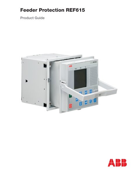
<strong>Feeder</strong> <strong>Protection</strong><strong>REF615</strong>1MRS756379Issue: February 2008Status: ApprovedVersion: B / 22 Feb 20081. Description<strong>REF615</strong> is a dedicated feeder protection relaydesigned for the protection, measurementand supervision of utility substations andindustrial power systems. Re-engineered fromthe ground up, the relay has been guided bythe IEC 61850 standard for communicationand interoperability of substation automationdevices.The relay provides main protection for overheadlines and cable feeders in distributionnetworks. The relay is also used as back-upprotection in applications, where an independentand redundant protection system isrequired.Depending on the preconfiguration made,the relay is adapted for the protection ofoverhead line and cable feeders in isolatedneutral, resistance earthed, compensated andsolidly earthed networks. Once the standardconfiguration relay has been given the application-specificsettings, it can directly be putinto service.The 615 series relays support a range of communicationprotocols including IEC 61850with GOOSE messaging and Modbus®.2. StandardconfigurationsThe feeder protection relay <strong>REF615</strong> is availablewith four alternative standard configurations.The table below indicates the functionssupported by the different relay configurations.Standard configuration functionalityOvercurrent anddirectional earth-faultprotectionStd.conf.AStd.conf.BOvercurrent and nondirectionalearth-fault protectionStd.conf.C<strong>Protection</strong>Three-phase non-directional overcurrent,low-set stage • • • •Three-phase non-directional overcurrent,high-set stage, instance 1 • • • •Three-phase non-directional overcurrent,high-set stage, instance 2 • • • •Three-phase non-directional overcurrent,instantaneous stage • • • •Directional earth-fault, low-set stage,instance 1 • • - -Directional earth-fault, low-set stage,instance 2 • • - -Directional earth-fault, high-set stage • • - -Non-directional earth-fault, high-set stage(cross country earth-fault) • • - -Transient/intermittent earth-fault • • - -Non-directional earth-fault, low-set stage - - • •Non-directional earth-fault, high-set stage - - • •Non-directional earth-fault,instantaneous stage- - • •Std.conf.D<strong>ABB</strong>
<strong>Feeder</strong> <strong>Protection</strong><strong>REF615</strong><strong>Protection</strong>, continuedNon-directional sensitive earth-fault - - • •Negative-sequence overcurrent,instance 1 • • • •Negative-sequence overcurrent,instance 2 • • • •Phase discontinuity • • • •Thermal overload • • • •Circuit breaker failure protection • • • •Three-phase inrush current detection • • • •Arc protection with three sensors o o o oControlCircuit breaker control with basicinterlocking 1) • • • •Circuit breaker control with extendedinterlocking 2)- • - •Auto-reclosing of one circuit breaker o o o oSupervision and MonitoringCircuit breaker condition monitoring - • - •Trip-circuit supervision of two tripcircuits • • • •MeasurementTransient disturbance recorder • • • •Three-phase current measurement • • • •Current sequence components • • • •Residual current measurement • • • •Residual voltage measurement • • - -• = Included, o = Optional at the time of the order1) Basic interlocking functionality: Closing of the circuit breaker can be enabled by a binary input signal. The actualinterlocking scheme is implemented outside the relay. The binary input serves as a “master interlocking input”and when energized it will enable circuit breaker closing.2) Extended interlocking functionality: The circuit breaker interlocking scheme is implemented in the relayconfiguration, based on primary equipment position information (via binary inputs) and the logical functionsavailable. The signal matrrix tool of PCM600 can be used for modifying the interlocking scheme to suit yourapplication.3. <strong>Protection</strong> functionsThe relay offers overcurrent and thermaloverload protection, directional and nondirectionalearth-fault protection, sensitive earthfaultprotection, phase discontinuity protection,transient/intermittent earth-fault protectionand three-pole multi-shot auto-reclosefunctions for overhead line feeders.Enhanced with optional hardware and software,the relay also features three lightdetection channels for arc fault protection ofthe circuit breaker, busbar and cable compartmentof metal-enclosed indoor switchgear.The arc-fault protection sensor interface isavailable on the optional communicationmodule. Fast tripping increases personalsafety and limits material damage within theswitchgear in an arc fault situation.<strong>ABB</strong>
<strong>Feeder</strong> <strong>Protection</strong><strong>REF615</strong>1MRS756379Fig. 1 <strong>Protection</strong> function overview of standard configuration A and BFig. 2 <strong>Protection</strong> function overview of standard configuration C and D<strong>ABB</strong>
<strong>Feeder</strong> <strong>Protection</strong><strong>REF615</strong>1MRS756379The standard configurations C and D offernon-directional earth-fault protection for outgoingfeeders including phase current transformers.The residual current for the earthfaultprotection is derived from the phasecurrents. When applicable, the core-balancecurrent transformers can be used for measuringthe residual current, especially whensensitive earth-fault protection is required.Fig. 4 Substation O/C and E/F protection using the standard configuration C or D withrelevant options. In the incoming feeder bay the unemployed protection functions areuncoloured and indicated with a dashed block outline. The busbar protection is basedon the interlocking principle, where the start of the O/C protection of the outgoing feedersends a blocking signal to the instantaneous O/C stage of the incoming feeder. In theabsence of the blocking signal, the O/C protection of the incoming feeder will clear theinternal switchgear (busbar) fault.<strong>ABB</strong>
<strong>Feeder</strong> <strong>Protection</strong><strong>REF615</strong>5. ControlThe relay offers control of one circuit breakerwith dedicated push-buttons for opening andclosing. Interlocking schemes required bythe application are configured with the signalmatrix tool in PCM600.6. MeasurementThe relay continuously measures the phasecurrents, the symmetrical components ofthe currents and the residual current. If therelay includes directional earth-fault protection,it also measures the residual voltage. Inaddition, the relay calculates the maximumdemand value over a user-selectable pre-settime frames, the thermal overload of the protectedobject, and the phase unbalance valuebased on the ratio between the negativesequence and positive sequence current.The values measured can be accessed locallyvia the user interface on the relay front panelor remotely via the communication interfaceof the relay. The values can also be accessedlocally or remotely using the web-browserbased user interface.7. Disturbance recorderThe relay is provided with a disturbancerecorder featuring up to eight analog and 32binary signal channels. The analog channelscan be set to record either the waveform orthe trend of the currents and voltage measured.The analog channels can be set to trigger therecording function when the measured valuefalls below or exceeds the set values. Thebinary signal channels can be set to start arecording on the rising or the falling edge ofthe binary signal or both.By default, the binary channels are set torecord external or internal relay signals, e.g.the start or trip signals of the relay stages, orexternal blocking or control signals. Binaryrelay signals such as a protection start ortrip signal, or an external relay control signalover a binary input can be set to trigger therecording.8. Event logTo collect sequence-of-events (SoE) information,the relay incorporates a memory witha capacity of storing 50 event codes with associatedtime stamps. The event log facilitatesdetailed pre- and post-fault analyses of feederfaults and disturbances.The SoE information can be accessed locallyvia the user interface on the relay front panelor remotely via the communication interfaceof the relay. The information can further beaccessed, either locally or remotely, using theweb-browser based user interface.9. Recorded dataThe relay has the capacity to store therecords of four fault events. The records enablethe user to analyze the four most recentpower system events. Each record includesthe current and voltage values, the start timesof the protection blocks, time stamp, etc. Thefault recording can be triggered by the startsignal or the trip signal of a protection block,or by both. The available measurement modesinclude DFT, RMS and peak-to-peak. In addition,the maximum demand current with timestamp is separately recorded.<strong>ABB</strong>
<strong>Feeder</strong> <strong>Protection</strong><strong>REF615</strong>1MRS75637910. Circuit-breakermonitoringThe condition monitoring functions of therelay constantly monitors the performanceand the condition of the circuit breaker. Themonitoring comprises the spring chargingtime, SF6 gas pressure, the travel-time andthe inactivity time of the circuit breaker.The monitoring functions provide operationalCB history data, which can be used forscheduling preventive CB maintenance.11. Trip-circuitsupervisionThe trip-circuit supervision continuouslymonitors the availability and operability ofthe trip circuit. It provides open-circuit monitoringboth when the circuit breaker is in itsclosed and in its open position. It also detectsloss of circuit-breaker control voltage.12. Self-supervisionThe relay’s built-in self-supervision systemcontinuously monitors the state of the relayhardware and the operation of the relaysoftware. Any fault or malfunction detectedwill be used for alerting the operator. A permanentrelay fault will block the protectionfunctions of the relay to prevent incorrectrelay operation.13. Access controlTo protect the relay from unauthorized accessand to maintain information integrity, therelay is provided with a four-level, role-basedauthentication system with administratorprogrammableindividual passwords for theviewer, operator, engineer and administratorlevel. The access control applies to the frontpaneluser interface, the web-browser baseduser interface and the PCM600 tool.14. Inputs and outputsDepending on the standard configurationselected, the relay is equipped with threephase-current inputs and one residual-currentinput for non-directional earth-fault protection,or three phase-current inputs, one residual-currentinput and one residual voltageinput for directional earth-fault protection.The phase-current inputs are rated 1/5 A.Two optional residual-current inputs areavailable, i.e. 1/5 A or 0.2/1 A. The 0.2/1 A inputis normally used in applications requiringsensitive earth-fault protection and featuringcore-balance current transformers. The residual-voltageinput covers the rated voltages100, 110, 115 and 120 V.The phase-current input 1 A or 5 A, the residual-currentinput 1 A or 5 A, alternatively 0.2A or 1 A, and the rated voltage of the residualvoltage input are selected in the relay software.In addition, the binary input thresholds18…176 V DC are selected by adjusting therelay’s parameter settings.All binary input and output contacts arefreely configurable with the signal matrix toolin PCM600.<strong>ABB</strong>
<strong>Feeder</strong> <strong>Protection</strong><strong>REF615</strong>Relay analog input and binary input/outputoverview:• Four current inputs• One optional voltage input (for directionalE/F protections applications)• Three binary inputs with U 0measurementand four binary inputs without U 0measurement• Two heavy-duty output relays with normally-opencontact• Two changeover signal-output contacts• Two double-pole power-output contactswith trip-circuit supervision• One dedicated IRF output contactI/O extension module:• Seven binary control inputs• Three signaling-output contacts15. CommunicationThe relay supports two different communicationprotocols: IEC 61850 and Modbus®. Operationalinformation and controls are availablethrough these protocols. However, somecommunication functionality, for example,horizontal communication between the relays,is only enabled by the IEC 61850 communicationprotocol.The IEC 61850 communication implementationsupports all monitoring and controlfunctions. Additionally, parameter setting anddisturbance file records can be accessed usingthe IEC 61850-8-1 protocol. Further, the relaycan send and receive binary signals fromother relays (so called horizontal communication)using the IEC61850-8-1 GOOSE profile,where the highest performance class with atotal transmission time of 3 ms is supported.The relay can simultaneously report to fivedifferent IEC 61850-8-1 clients.All communication connectors, except for thefront port connector, are placed on integratedoptional communication modules. The relaycan be connected to Ethernet-based communicationsystems via the RJ-45 connector(100BASE-TX) or the fibreoptic LC connector(100BASE-FX). If connection to a RS-485 networkis required, the 10-pin screw-terminalconnector can be used.Modbus implementation supports RTU, ASCIIand TCP modes. Besides standard Modbusfunctionality, the relay supports retrievalof time-stamped events, uploading of disturbancefiles and storing of the latest faultrecords. If a Modbus TCP connection is used,five clients can be connected to the relaysimultaneously.When the relay uses the RS-485 bus for theModbus RTU/ASCII communication, bothtwo- and four wire connections are supported.Termination and pull-up/down resistorscan be configured with jumpers on the communicationcard so external resistors are notneeded.The relay supports the following time synchronizationmethod with a time-stamping resolutionof +/-1 ms:Ethernet based:• SNTPSupported communication interfaces and protocols100BASE-TXRJ45100BASE-FX LCIEC 61850-8-1 • • -MODBUS RTU/ASCII - - •MODBUS TCP • • -RS-48510<strong>ABB</strong>
<strong>Feeder</strong> <strong>Protection</strong><strong>REF615</strong>1MRS75637916. Technical dataDimensionsWidth frame 177 mm,case 164 mmHeight frame 177 (4U)case 160 mmDepth case 155 mmWeight relay 3.5 kgspare unit 1.8 kgPower SupplyType: Type 1 Type 2U auxnominalU auxvariationStart-up thresholdBurden of auxiliary voltage supplyunder quiescent (Pq)/operatingconditionRipple in the DC auxiliary voltage100, 110, 120, 220, 240 V AC,50 and 60 Hz48, 60, 110, 125, 220, 250 V DC85...110% of U n(85...264 V AC)80...120% of U n(38.4...300 VDC)
<strong>Feeder</strong> <strong>Protection</strong><strong>REF615</strong>Energizing inputsRated frequency50/60 Hz ± 5 HzCurrent inputs Rated current, I n 0.2/1 A 1) 1/5 A 2)Thermal withstand capability:• Continuously• For 1 s• For 10 s4 A100 A25 A20 A500 A100 ADynamic current withstand:• Half-wave value 250 A 1250 AInput impedance
<strong>Feeder</strong> <strong>Protection</strong><strong>REF615</strong>1MRS756379IRF relay change over - type signal output relayRated voltageContinuous contact carryMake and carry for 3.0 sMake and carry 0.5 sBreaking capacity when the control-circuit timeconstant L/R
<strong>Feeder</strong> <strong>Protection</strong><strong>REF615</strong>Degree of protection of flush-mounted relayFront side IP 54Rear side, top of the relay IP 40Rear side, connection terminals IP 20Environmental conditions and testsEnvironmental conditionsOperating temperature rangeShort-time service temperature rangeRelative humidityAtmospheric pressureAltitudeTransport and storage temperature range-25...+55ºC (continuous)-40...+85ºC (
<strong>Feeder</strong> <strong>Protection</strong><strong>REF615</strong>1MRS756379(continued)Radio frequency interference tests:• Conducted, common mode• Radiated, amplitude-modulated• Radiated, pulse-modulatedFast transient disturbance tests:• All ports• CommunicationSurge immunity test:• All ports• CommunicationPower frequency (50 Hz) magnetic field:• Continuous• 1...3 sPower frequency immunity test:• Common mode• Differential modeAccording to IEC 61000-4-6andIEC 60255-22-6, level 3 10 V(emf), f = 150 kHz...80 MHzAccording to IEC 61000-4-3and IEC 60255-22-3, level 3 10V/m (rms), f=80...1000 MHzand f=1.4...2.7 GHzAccording to the ENV 50204and IEC 60255-22-3,level 3 10V/m, f=900 MHzAccording to IEC 61000-4-4and IEC 60255-22-4, class B2 kV2 kVAccording to IEC 61000-4-5and IEC 60255-22-5, level 4/32 kV, line-to-earth, 1kV, line-toline1 kV, line-to-earthAccording to IEC 61000-4-8,level 5300 A/m1000 A/mAccording to IEC 60255-22-7,class A300 V rms150 V rmsVoltage dips and short interruptions According to IEC 61000-4-1130%/10 ms60%/100 ms60%/1000 ms>95%/5000 ms<strong>ABB</strong> 15
<strong>Feeder</strong> <strong>Protection</strong><strong>REF615</strong>Insulation and mechanical testsInsulation testsDielectric tests: According to IEC 60255-5• Test voltage2 kV, 50 Hz, 1 min 500 V, 50Hz, 1min, communicationImpulse voltage test: According to IEC 60255-5• Test voltage5 kV, unipolar impulses,waveform 1.2/50 μs, sourceenergy 0.5 J 1 kV, unipolarimpulses, waveform 1.2/50μs, source energy 0.5 J, communicationInsulation resistance measurements According to IEC 60255-5• Isolation resistanceProtective bonding resistance• Resistance>100 MΩ, 500 V DCAccording to IEC 60255-27
<strong>Feeder</strong> <strong>Protection</strong><strong>REF615</strong>1MRS756379<strong>Protection</strong> functionsThree-phase non-directional overcurrent protection (PHxPTOC)OperationaccuracyDepending on the frequency of the current measured: f n ±2HzPHLPTOCPHHPTOCandPHIPTOC±1.5% of the set value or ±0.002 x I n±1.5% of set value or ±0.002 x I n(at currents in the range of 0.1…10 x I n )±5.0% of the set value(at currents in the range of 10…40 x I n )Start time 1) 2) Minimum Typical MaximumPHIPTOC:I Fault = 2 x set Start valueI Fault = 10 x set Start value16 ms11 ms19 ms12 ms23 ms14 msPHHPTOC and PHLPTOC:I Fault = 2 x set Start value 22 ms 24 ms 25 msInstantaneousMinimum Typical Maximumoperate time 1) 3)Reset timePHIPTOC:I Fault = 2 x set Start valueI Fault = 10 x set Start value17 ms12 ms21 ms15 ms25 ms16 msPHHPTOC and PHLPTOC:I Fault = 2 x set Start value 25 ms 27 ms 29 ms< 40 msReset ratio Typical 0.96Retardation timeOperate time accuracy in definite time mode< 30 ms±1.0% of the set value or ±20 msOperate time accuracy in inverse time mode ±5.0% of the theoretical value or ±20ms 4)Suppression of harmonics RMS: No suppression DFT: -50dB at f =n x f n , where n = 2, 3, 4, 5,…Peak-to-Peak: No suppressionP-to-P+backup: No suppression1) Set Operate delay time = 0,02 s, Operate curve type = IEC definite time, Measurement mode = default (depends onstage), current before fault = 0.0 x In, fn = 50 Hz, fault current in one phase with nominal frequency injected fromrandom phase angle, results based on statistical distribution of 1000 measurements.2) Includes the delay of the signal output contact3) Includes the delay of the heavy-duty output contact4) Maximum Start value = 2.5 x In, Start value multiples in range of 1.5 to 20<strong>ABB</strong> 17
<strong>Feeder</strong> <strong>Protection</strong><strong>REF615</strong>Non-directional EF protection (EFxPTOC)OperationaccuracyDepending on the frequency of the current measured: f n ±2HzEFLPTOCEFHPTOCandEFIPTOC±1.5% of the set value or ±0.002 x I n±1.5% of set value or ±0.002 x I n(at currents in the range of 0.1…10 x I n )±5.0% of the set value(at currents in the range of 10…40 x I n )Start time 1) 2) Minimum Typical MaximumEFIPTOC:I Fault = 2 x set Start valueI Fault = 10 x set Start value16 ms11 ms19 ms12 ms23 ms14 msEFHPTOC and EFLPTOC:I Fault = 2 x set Start value 22 ms 24 ms 25 msInstantaneousMinimum Typical Maximumoperate time 1) 3)Reset timeEFIPTOC:I Fault = 2 x set Start valueI Fault = 10 x set Start value19 ms14 ms23 ms16 ms27 ms17 msEFHPTOC and EFLPTOC:I Fault = 2 x set Start value 24 ms 27 ms 29 ms< 40 msReset ratio Typical 0.96Retardation timeOperate time accuracy in definite time modeOperate time accuracy in inverse time mode< 30 ms±1.0% of the set value or ±20 ms±5.0% of the theoretical value or ±20 msSuppression of harmonics RMS: No suppression DFT: -50dB at f =n x f n , where n = 2, 3, 4, 5,…Peak-to-Peak: No suppression1) Set Operate delay time = 0,02 s, Operate curve type = IEC definite time, Measurement mode = default (depends onstage), current before fault = 0.0 x In, fn = 50 Hz, earth-fault current with nominal frequency injected from randomphase angle, results based on statistical distribution of 1000 measurements2) Includes the delay of the signal output contact3) Includes the delay of the heavy-duty output contact4) Maximum Start value = 2.5 x In, Start value multiples in range of 1.5 to 204)18<strong>ABB</strong>
<strong>Feeder</strong> <strong>Protection</strong><strong>REF615</strong>1MRS756379Directional EF protection (DEFxPDEF)OperationaccuracyDepending on the frequency of the current measured: f n ±2HzDEFLPDEFDEFHPDEFCurrent:±1.5% of the set value or ±0.002 x I nVoltage:±1.5% of the set value or ±0.002 x U nPhase angle:±2°Current:±2% of the set value or ±0.003 x I n(at currents in the range of 0.1…10 x I n)±5.0% of the set value(at currents in the range of 10…40 x I n)Voltage:±1.5% of the set value or ±0.01 x U nPhase angle:±2°Start time 1) 2) Minimum Typical MaximumDEFHPDEF andDEFLPTDEF:I Fault = 2 x set Start value 61 ms 64 ms 66 msInstantaneousMinimum Typical Maximumoperate time 1) 3) DEFHPDEF andDEFLPDEF:I Fault = 2 x set Start value 62 ms 67 ms 69 msReset time< 40 msReset ratio Typical 0.96Retardation timeOperate time accuracy in definite time mode< 30 ms±1.0% of the set value or ±20 msOperate time accuracy in inverse time mode ±5.0% of the theoretical value or ±20 ms 4)Suppression of harmonics RMS: No suppression DFT: -50dB at f =n x f n , where n = 2, 3, 4, 5,…Peak-to-Peak: No suppression1) Set Operate delay time = 0,02 s, Operate curve type = IEC definite time, Measurement mode = default (dependson stage), current before fault = 0.0 x In, fn = 50 Hz, earth-fault current with nominal frequency injected fromrandom phase angle, results based on statistical distribution of 1000 measurements2) Includes the delay of the signal output contact3) Includes the delay of the heavy-duty output contact4) Maximum Start value = 2.5 x In, Start value multiples in range of 1.5 to 20<strong>ABB</strong> 19
<strong>Feeder</strong> <strong>Protection</strong><strong>REF615</strong>Transient/intermittent earth-fault protection (INTRPTEF)Operation accuracy (U0 criteria with transientprotection)Operate time accuracyDepending on the frequency of the currentmeasured: f n = ±2Hz±1.5% of the set value or ±0.002 x U n±1.0% of the set value or ±20 msSuppression of harmonics DFT: -50dB at f = n x f n , where n = 2, 3, 4, 5Negative phase-sequence current protection (NSPTOC)Operation accuracyDepending on the frequency of thecurrent measured: f n = ±2Hz±1.5% of the set value or ±0.002 x I nStart time 1) 2) Minimum Typical MaximumI Fault = 2 x set Start valueI Fault = 10 x set Start value22 ms14 ms24 ms16 ms25 ms17 msInstantaneousMinimum Typical Maximumoperate time 1) 3) I Fault = 2 x set Start value 24 ms 26 ms 28 msReset time< 40 msReset ratio Typical 0.96Retardation timeOperate time accuracy in definite time mode< 35 ms±1.0% of the set value or ±20 msOperate time accuracy in inverse time mode ±5.0% of the theoretical value or ±20 ms 4)Suppression of harmonicsDFT: -50dB at f = n x f n , wheren = 2, 3, 4, 5,…1)Set Operate delay time = 0,02 s, Operate curve type = IEC definite time, negative sequence current beforefault = 0.0, f n = 50 Hz, results based on statistical distribution of 1000 measurements2)Includes the delay of the signal output contact3)Includes the delay of the heavy-duty output contact4)Maximum Start value = 2.5 x I n , Start value multiples in range of 1.5 to 20Phase discontinuity protection (PDNSPTOC)Operation accuracyStart timeReset timeDepending on the frequency of the currentmeasured: fn ±2Hz±2% of the set value< 70 ms< 40 msReset ratio Typical 0.96Retardation timeOperate time accuracy in definite time mode< 35 ms±1.0% of the set value or ±20 msSuppression of harmonics DFT: -50dB at f = n x fn, where n = 2, 3, 4,5,…20<strong>ABB</strong>
<strong>Feeder</strong> <strong>Protection</strong><strong>REF615</strong>1MRS756379Three-phase thermal overload (T1PTTR)Operation accuracyOperate time accuracyDepending on the frequency of the currentmeasured: fn ±2HzCurrent measurement: ±0.5% or ±0.002 x I n(at currents in the range of 0.01…4.00 x I n )±2.0% or ±0.50 sCircuit breaker failure protection (CCBRBRF)Operation accuracyOperate time accuracyDepending on the frequency of the currentmeasured: fn ±2Hz±1.5% of the set value or ±0.002 x I n±1.0% of the set value or ±20 msThree-phase inrush current detection (INRPHAR)Operation accuracyReset timeAt the frequency f=f nCurrent measurement:±1.5% of set value or ±0.002 x InRatio I2f/I1f measurement: ±5.0% of set value+35 ms / -0 msReset ratio Typical 0.96Operate time accuracy+35 ms / -0 msArc protection (ARCSARC)Operation accuracy±3% of the set value or ±0.01 x I nOperate time Minimum Typical MaximumReset timeOperation mode =“Light+current” 1) 2) 9 ms 12 ms 15 msOperation mode =“Light only” 2) 9 ms 10 ms 12 ms< 40 msReset ratio Typical 0.961) Phase start value = 1.0 x In, current before fault = 2.0 x set Phase start value, fn = 50Hz, fault with nominalfrequency, results based on statistical distribution 200 measurements2) Includes the delay of the heavy-duty output contactControl functionsAutoreclosure (DARREC)Operation accuracy±1.0% of the set value or ±20 ms<strong>ABB</strong> 21
<strong>Feeder</strong> <strong>Protection</strong><strong>REF615</strong>17. Display optionsThe relay is available with two optional displays,a large one and a small one. Both LCDdisplays offer full front-panel user-interfacefunctionality with menu navigation and menuviews.The large display offers increased frontpanelusability with less menu scrolling andimproved information overview. The largedisplay is suited for relay installations wherethe front panel user interface is frequentlyused, whereas the small display is suited forremotely controlled substations where therelay is only occasionally accessed locally viathe front panel user interface.Fig. 5 Small displayFig. 6 Large displaySmall displayCharacter size 1) Rows in the view Characters per rowSmall, mono-spaced (6x12 pixels) 5 20Large, variable width (13x14 pixels) 4 8 or more 1)Large displayCharacter size 1) Rows in the view Characters per rowSmall, mono-spaced (6x12 pixels) 10 20Large, variable width (13x14pixels) 8 8 or more 1)1) Depending on the selected language22<strong>ABB</strong>
153 41103 91<strong>Feeder</strong> <strong>Protection</strong><strong>REF615</strong>1MRS75637918. Mounting methodsBy means of appropriate mounting accessoriesthe standard relay case for the 615series relays can be flush mounted, semi-flushmounted or wall mounted. The flush mountedand wall mounted relay cases can alsobe mounted in a tilted position (25°) usingspecial accessories.Further, the relays can be mounted in anystandard 19” instrument cabinet by means of19” mounting panels available with cut-outsfor one or two relays. Alternatively, the relayscan be mounted in 19” instrument cabinets bymeans of 4U Combiflex equipment frames.For the routine testing purposes, the relaycases can be equipped with test switches,type RTXP 18, which can be mounted side byside with the relay cases.Mounting methods:• Flush mounting• Semi-flush mounting• Semi-flush mounting in a 25° tilt• Rack mounting• Wall mounting• Mounting to a 19” equipment frame• Mounting with a RTXP 18 test switchto a 19”rackPanel cut-out for flush mounting:• Height: 161.5±1 mm• Width: 165.5±1 mm19. Relay case and relayplug-in unitFor safety reasons, the relay cases for currentmeasuring relays are provided with automaticallyoperating contacts for short-circuitingthe CT secondary circuits when a relay unitis withdrawn from its case. The relay case isfurther provided with a mechanical codingsystem preventing current measuring relayunits from being inserted into a relay case fora voltage measuring relay unit and vice versa,i.e. the relay cases are assigned to a certaintype of relay plug-in unit.127221,25 (5U)25°1075Fig. 7 Flush mounting Fig. 8 Semi-flush mounting Fig. 9 Semi-flush with a25º tilt<strong>ABB</strong> 23
<strong>Feeder</strong> <strong>Protection</strong><strong>REF615</strong>20. Selection andordering dataThe relay type and serial number label identifiesthe protection relay. The label is placedabove the HMI on the upper part of the plugin-unit.An order number label is placed onthe side of the plug-in-unit as well as insidethe case. The order number consists of astring of codes generated from the hardwareand software modules of the relay.Use the ordering key information in Fig. 10to generate the order number when orderingcomplete protection relays.H B F C A C A B N B B 1 A C N 1 X A# DESCRIPTION1 Relay615 series relay (including case) H2 StandardIECB3 Main application<strong>Feeder</strong> protectionFH B F C A C A B N B B 1 A C N 1 X A# DESCRIPTION4 Functional application 1)Standard configuration A B C D5-6 Analog inputs4 I + U 0(I 01/5 A) AA AA4 I + U 0(I 00.2/1 A) AB AB4 I (I 01/5 A) AC AC4 I (I 00.2/1 A) AD AD7-8 Binary inputs/outputs3 BI + 6 BO AA4 BI + 6 BO AB10 BI + 9 BO AC11 BI + 9 BO AD1)The selected standard configuration defines the requiredand optional hardware. Select the correct digits from thestandard configuration column A, B, C or D.24<strong>ABB</strong>
<strong>Feeder</strong> <strong>Protection</strong><strong>REF615</strong>1MRS756379H B F C A C A B N B B 1 A C N 1 X A# DESCRIPTION9 Communication serialRS485None N N10 Communication EthernetEthernet 100BaseFX (LC)Ethernet 100BaseTX (RJ45)None N N11 Communication protocol 1)IEC 61850 A AModbus B B1)The selected communication module (digit 9-10) specifiesthe available communication protocols. Select your protocolfrom the relevant column.AABH B F C A C A B N B B 1 A C N 1 X A# DESCRIPTION12 LanguageEnglish 113 Front panelSmall LCDLarge LCD14 Option 1ReclosingArc protection 1)Arc protection and reclosing 1)None15 Option 2None16 Power supply48...250 V DC, 100...240 V AC 124...60 V DC 217 Vacant digitVacant18 VersionVersion 1.01)The arc protection hardware is located on the communicationmodule (digit 9-10). Thus a communication module is alwaysrequired to enable arc protection.ABABCNNXA<strong>ABB</strong> 25
<strong>Feeder</strong> <strong>Protection</strong><strong>REF615</strong>Example code: H B F C A C A B N B B 1 A C N 1 X AYour ordering code:Digit (#) 1 2 3 4 5 6 7 8 9 10 11 12 13 14 15 16 17 18Code Fig. 10 Ordering key for complete relays26<strong>ABB</strong>
<strong>Feeder</strong> <strong>Protection</strong><strong>REF615</strong>1MRS75637921. Accessories andordering dataItemOrder nrCablesCable for optical sensors for arc protection 1.5 m1MRS120534-1.5Cable for optical sensors for arc protection 3.0 m1MRS120534-3.0Cable for optical sensors for arc protection 5.0 m1MRS120534-5.0Mounting accessoriesSemi-flush mounting kit1MRS050696Wall mounting kit1MRS050697Inclined semi-flush mounting kit1MRS05083119 ” rack mounting kit with cutout for one relay 1MRS05069419 ” rack mounting kit with cutout for two relays 1MRS050695Mounting kit for RTXP 18 (4U Combiflex)1MRS051010Mounting kit for 4U high Combiflex equipment frame1MRS050779Test switches:Test switch RTXP 18 mounting kit for 19” rack, single relay 1MRS05078322. ToolsThe relay is delivered as a pre-configuredunit. The default parameter setting values canbe changed from the front-panel user interface,the web-browser based user interface(WebHMI) or the PCM600 tool in combinationwith the relay specific connectivity package.PCM600 offers extensive relay configurationfunctions such as relay signal configurationusing the signal matrix tool, and IEC 61850communication configuration including horizontalrelay-to-relay communication, GOOSE.ToolsConfiguration, setting and SA system toolsPCM600Web-browser based user interface<strong>REF615</strong> Connectivity PackageMicroSCADA ProWhen the web-browser based user interfaceis used, the relay can be accessed either locallyor remotely using a web browser (IE7.0 or later). For security reasons, the webbrowserbased user interface is disabled bydefault. The interface can be enabled withthe PCM600 tool or from the front panel userinterface. The functionality of the interfacecan be limited to read-only access by meansof PCM600.Version2.0 or laterIE 7.0 or later1.0 or later9.2 SP1 or later<strong>ABB</strong> 27
<strong>Feeder</strong> <strong>Protection</strong><strong>REF615</strong>Tool function overviewFunction WebHMI PCM600Relay signal configuration (signal matrix tool) -•IEC 61850 communication configuration, GOOSE -•Relay parameter setting • •Signal monitoring • •Disturbance recorder handling - •Disturbance record analysis -•Event viewing •-Alarm LED viewing • •Phasor diagram viewing •-Saving of relay parameter settings in the relay • •Saving of parameter settings in the tool -•Access control management • •• = Supported28<strong>ABB</strong>
<strong>Feeder</strong> <strong>Protection</strong><strong>REF615</strong>1MRS75637923. Terminal diagramsFig. 11: Terminal diagram of standard configuration B<strong>ABB</strong> 29
<strong>Feeder</strong> <strong>Protection</strong><strong>REF615</strong>Fig. 12: Terminal diagram of standard configuration D30<strong>ABB</strong>
<strong>Feeder</strong> <strong>Protection</strong><strong>REF615</strong>1MRS75637924. Functions, codesand symbols<strong>REF615</strong> functions, codes and symbols<strong>Protection</strong> functions IEC 61850 IEC60617Three-phase non-directional overcurrent, low-setstageThree-phase non-directional overcurrent, high-setstageANSIPHLPTOC 3I> 51P-1PHHPTOC 3I>> 51P-2Three-phase non-directional overcurrent,instantaneous stage PHIPTOC 3I>>> 50P/51PDirectional earth-fault, low-set stage DEFLPDEF I 0 >→ 67N-1Directional earth-fault, high-set stage DEFHPDEF I 0 >>→ 67N-2Transient/intermittent earth-fault INTRPTEF I 0 >→ IEF 67N-IEFNon-directional earth-fault, low-set stage (SEF) EFLPTOC I 0 > 51N-1Non-directional earth-fault, low-set stage EFLPTOC I 0 > 51N-1Non-directional earth-fault, high-set stage EFHPTOC I 0 >> 51N-2Non-directional earth-fault, instantaneous stage EFIPTOC I 0 >>> 50N/51NNegative-sequence overcurrent NSPTOC I 2 > 46Phase discontinuity PDNSPTOC I 2 /I 1 > 46PDThermal overload T1PTTR 3I th > 49FCircuit breaker failure protection CCBRBRF 3I>/I 0 >BF 51BF/51NBFThree-phase inrush current detector INRPHAR 3I2f> 68Arc protection ARCSARC ARC 50L/50NLControl functionsCircuit-breaker control CBXCBR I ↔ O CBAutoreclosing DARREC O→ I 79Measurement functionsThree-phase current CMMXU 3I 3ICurrent sequence components CSMSQI I 1,I 2,I 0 I 1,I 2,I 0Residual current RESCMMXU I 0 I NResidual voltage RESVMMXU U 0 V NDisturbance recorder functionTransient disturbance recorder DRRDRE DREC DRECCB conditioning monitoring functionCircuit-breaker condition monitoring SSCBR CBCM CBCMSupervision functionTrip-circuit supervision TCSSCBR TCS TCM<strong>ABB</strong> 31
<strong>ABB</strong> OyDistribution AutomationP.O. Box 699FI-65101 VAASA, FinlandPhone +358 10 22 11Fax +358 10 22 41094www.abb.com/substationautomation1MRS756379 B © Copyright 2008 <strong>ABB</strong>. All rights reserved.