The Black Widow - A Portable 15 Meter Beam - KG4JJH
The Black Widow - A Portable 15 Meter Beam - KG4JJH
The Black Widow - A Portable 15 Meter Beam - KG4JJH

You also want an ePaper? Increase the reach of your titles
YUMPU automatically turns print PDFs into web optimized ePapers that Google loves.
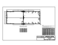
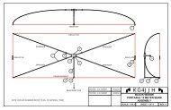
Figure 4––One of the two insulators forthe wire elements.Figure 5––<strong>The</strong> mounted terminal strip onthe feeder arm.fashioned from the explanations containedhere; however, detailed constructiondrawings for the antenna and the mastcomponents are available at www.arrl.org/files/qst-binaries/blackwidow.zip.SpreadersModify each of the four fishing polesas follows. Unscrew the handle cap,roughen two inches of the inside surfacewith sandpaper, and epoxy a 12″ woodenextension pole (threaded on both ends) intothe fishing pole handle. <strong>The</strong> original poleis too flexible and does not exert enoughtension to keep the wires tight, so a portionof the small end must be removed.Extend the pole to its full length, and trimthe small end so that the total length fromhandle to tip (including the wooden pole)is 106.5″. Use a hacksaw or band saw tokeep the fiberglass from cracking. Epoxya screw hook into the end of the pole.(Note: If the screw hook diameter is toolarge to fit into the end of the pole, cutanother 0.5″ to 1″ off of the pole until itfits. Make all four poles the same length.)Spray paint the bare wood with KrylonUltra-Flat black spray paint, and when dryapply two coats of clear lacquer.Center Hub<strong>The</strong> center hub is made from 0.5″ thickpoplar wood to minimize weight. Cut thepieces on a table saw and glue them togetherwith yellow wood glue. Cut two ofthe plastic extension-pole handle socketsin half so that two threaded sockets areproduced from each. Drill 1″ diameterholes in the hub, and epoxy the sockets intoeach hole. I chose to permanently attachthe mast mount (which is a wooden extensionpole threaded on one end) by drillinga 0.875″ hole through the top and bottomand securing it with epoxy. Extend the nonthreadedend through the hub and trim offthe excess after the glue sets.Drill a 0.625″ hole for mounting theSO-239 connector on one side of the hub.Drill and mount the CPVC drop ear elbowon the opposite side, and drill a 0.3125″hole through the drop ear elbow into thehub. Sand and paint the hub the same asthe fishing pole handles. Figure 3 shows acompleted hub.Figure 6––A view of the antenna mastsupport bracket.Insulators<strong>The</strong> ends of the antenna elements(within dimension C of Figure 1) are supportedby a pair of insulators that maintaina fixed distance between the wireends. <strong>The</strong> insulators are made from 6″ ×0.75″ pieces of scrap CPVC pipe cut inhalf lengthwise. Six 0.3125″ holes aredrilled into the PVC insulators to reduceweight. Drill a small hole for a #6 threadcuttingscrew to attach the element endsto the insulators. Include the diameter ofthe solder rings when spacing the holesin the insulators. A view of each of theinsulators can be seen in Figure 4.WireCut wires to the following dimensions(including 0.4″ for each loop of wirearound a screw hook):Two each, ½ Driven Element = ½ A +B + 1 Loop= 97.3<strong>15</strong>″ + 29.875″ + 0.4″ = 127.59″or 127.625″One each, Reflector Element = A + 2D+ 2 Loops= 194.625″ + 72″ + 0.8″ = 267.425″or 267.5″Mark the corners (Figure 1, dimensionintersections A-B and A-D) on the wiresusing a permanent marker. Strip ½″ insulationfrom the wire ends at the feedpoint for the driven element. Attach solderrings at the ends that will attach tothe insulators.Feed Point and Feed Line SupportCoax is carried to the feed point of thedriven element from an SO-239 connec-May 2003 3