The Black Widow - A Portable 15 Meter Beam - KG4JJH
The Black Widow - A Portable 15 Meter Beam - KG4JJH
The Black Widow - A Portable 15 Meter Beam - KG4JJH

Create successful ePaper yourself
Turn your PDF publications into a flip-book with our unique Google optimized e-Paper software.
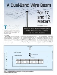
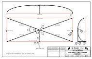
By Allen Baker, <strong>KG4JJH</strong><strong>The</strong> <strong>Black</strong><strong>Widow</strong>––A <strong>Portable</strong><strong>15</strong> <strong>Meter</strong> <strong>Beam</strong>Looking for a portable <strong>15</strong>-meter antennafor camping or Field Day? Four fishingpoles, 50 feet of wire, a few pieces ofwood, some PVC and a painter’s polemake a stinging portable performer.<strong>The</strong> Lure<strong>The</strong>re are a lot of excellent antennadesigns available to the amateur, but fewcan combine light weight and portabilitywith the significant gain and front-tobackratio (F/B) of the Moxon Rectangle.All the materials necessary for buildingthis portable antenna (including the mast)are available from your local Wal-Mart,Home Depot and RadioShack for under$125.<strong>The</strong> Moxon Rectangle<strong>The</strong> Moxon Rectangle is a twoelementbeam with considerable gain,high F/B ratio, and a direct match to 50Ω coax. [<strong>The</strong> Moxon-type antenna isnamed for its originator, L. A. Moxon,G6XN.—Ed.] <strong>The</strong> antenna is a derivativeof the Moxon Square and it has been furtheroptimized by L. B. Cebik, W4RNL. 1Figure 1 shows the basic dimensions ofthe antenna.I used the program MoxGen 2 to generatea model at 21.070 MHz for use withPSK and then fine-tuned it with EZNEC. 3Since the <strong>Black</strong> <strong>Widow</strong> uses insulatedwire (and MoxGen is based on bare wire),the final dimensions will change due tothe insulation’s effect on the wire’s velocityfactor.I first built the antenna to the wirelengths in the EZNEC model: A = 203.25″,B = 31.25″, C = 4.88″ and D = 37.63″,which resulted in an actual resonant frequencyof 20.180 MHz. I trimmed thewires to a final length = FM/FD × L, whereFM is the measured frequency, FD is thedesired frequency and L is the length beforetrimming. <strong>The</strong> final dimensions areA = 194.63″, B = 29.88″, C = 4.75″ andD = 36.0″. For an antenna centered in themiddle of the <strong>15</strong>-meter band: A = 193.75″,B = 29.75″, C = 4.63″ and D = 35.88″.ConstructionFigure 2 presents an overview of antennaassembly. All of the necessary materialsare listed in Table 1 along withsources for each. <strong>The</strong> antenna can be1Notes appear on page 00. Figure 1––<strong>The</strong> basic dimensions of the Moxon Rectangle.May 2003 1
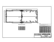
Table 1Materials List for the <strong>Black</strong> <strong>Widow</strong> AntennaItem Qty Description Source PriceEach ($)1 4 each Crappie Master Fishing Wal-Mart 6.96Pole, RCM-10LW, 3 sections, 10 ft2 1 roll 20 AWG insulated RadioShack 2.99stranded wire, 75 ft 278-12193 1 each Terminal strip, 8-position RadioShack 2.49274-6784 1 each Connector, SO-239 RadioShack 1.99278-20<strong>15</strong> 1 pkg Soldering ring, #6 RadioShack 1.6964-3030A6 1 each Epoxy, quick set Home Depot 2.977 4 each Screw hook, 0.162″ Home Depot 0.42wire diameter8 1 each Wood, poplar,½″ × 6″ × 36″ Home Depot 5.259 2 pkg Three piece extension pole, Home Depot 3.79Linzer RP503Item Qty Description Source PriceEach ($)10 1 each Painter Pole, Mr. LongArm Home Depot 39.97Model 232411 1 each PVC coupling, 1½″ Home Depot 0.4712 1 each CPVC pipe, ½″ × 10 ft Home Depot 2.9813 1 each CPVC drop ear 90° elbow, Home Depot 0.68½″14 1 each CPVC 90° elbow, ½″ Home Depot 0.19<strong>15</strong> 10 each Sheet metal screw, Home Depot 0.17self-drilling, #6 × ½″16 230 ft Nylon twine, #36 Home Depot 3.7917 3 each Clothesline tightener, Wal-Mart 2.96Lehigh 709718 50 ft Nylon rope, 3 /16″ Wal-Mart 1.9719 1 each 2″ × 4″ × 8′, pine Home Depot 3.0020 2 each L-bracket, 3″ × 3″ × ¾″ Home Depot 3.0021 5.5 ft RG-8X coaxial cable RadioShack 0.32278-1313 or per ftequivFigure 2––Overview of the antenna and its components. Circled numbers refer to materials in Table 1.Figure 3––<strong>The</strong> center hub(left). Note the glued-in (epoxy)threaded sockets for thespreaders. <strong>The</strong> completed hub(right) shows the mountingstub extending upward and thefeed line support extending tothe lower left.2 May 2003
Figure 4––One of the two insulators forthe wire elements.Figure 5––<strong>The</strong> mounted terminal strip onthe feeder arm.fashioned from the explanations containedhere; however, detailed constructiondrawings for the antenna and the mastcomponents are available at www.arrl.org/files/qst-binaries/blackwidow.zip.SpreadersModify each of the four fishing polesas follows. Unscrew the handle cap,roughen two inches of the inside surfacewith sandpaper, and epoxy a 12″ woodenextension pole (threaded on both ends) intothe fishing pole handle. <strong>The</strong> original poleis too flexible and does not exert enoughtension to keep the wires tight, so a portionof the small end must be removed.Extend the pole to its full length, and trimthe small end so that the total length fromhandle to tip (including the wooden pole)is 106.5″. Use a hacksaw or band saw tokeep the fiberglass from cracking. Epoxya screw hook into the end of the pole.(Note: If the screw hook diameter is toolarge to fit into the end of the pole, cutanother 0.5″ to 1″ off of the pole until itfits. Make all four poles the same length.)Spray paint the bare wood with KrylonUltra-Flat black spray paint, and when dryapply two coats of clear lacquer.Center Hub<strong>The</strong> center hub is made from 0.5″ thickpoplar wood to minimize weight. Cut thepieces on a table saw and glue them togetherwith yellow wood glue. Cut two ofthe plastic extension-pole handle socketsin half so that two threaded sockets areproduced from each. Drill 1″ diameterholes in the hub, and epoxy the sockets intoeach hole. I chose to permanently attachthe mast mount (which is a wooden extensionpole threaded on one end) by drillinga 0.875″ hole through the top and bottomand securing it with epoxy. Extend the nonthreadedend through the hub and trim offthe excess after the glue sets.Drill a 0.625″ hole for mounting theSO-239 connector on one side of the hub.Drill and mount the CPVC drop ear elbowon the opposite side, and drill a 0.3125″hole through the drop ear elbow into thehub. Sand and paint the hub the same asthe fishing pole handles. Figure 3 shows acompleted hub.Figure 6––A view of the antenna mastsupport bracket.Insulators<strong>The</strong> ends of the antenna elements(within dimension C of Figure 1) are supportedby a pair of insulators that maintaina fixed distance between the wireends. <strong>The</strong> insulators are made from 6″ ×0.75″ pieces of scrap CPVC pipe cut inhalf lengthwise. Six 0.3125″ holes aredrilled into the PVC insulators to reduceweight. Drill a small hole for a #6 threadcuttingscrew to attach the element endsto the insulators. Include the diameter ofthe solder rings when spacing the holesin the insulators. A view of each of theinsulators can be seen in Figure 4.WireCut wires to the following dimensions(including 0.4″ for each loop of wirearound a screw hook):Two each, ½ Driven Element = ½ A +B + 1 Loop= 97.3<strong>15</strong>″ + 29.875″ + 0.4″ = 127.59″or 127.625″One each, Reflector Element = A + 2D+ 2 Loops= 194.625″ + 72″ + 0.8″ = 267.425″or 267.5″Mark the corners (Figure 1, dimensionintersections A-B and A-D) on the wiresusing a permanent marker. Strip ½″ insulationfrom the wire ends at the feedpoint for the driven element. Attach solderrings at the ends that will attach tothe insulators.Feed Point and Feed Line SupportCoax is carried to the feed point of thedriven element from an SO-239 connec-May 2003 3
tor on the hub, through the hub, andthrough an “L” made of CPVC pipe. <strong>The</strong>horizontal pipe length is 31.5″, and thevertical length is 24″. <strong>The</strong>se lengths weredetermined with the antenna wires installedand the terminal block floatingfrom its vertical support. To account forconstruction differences, cut the pipepieces slightly long and trim them insmall increments.Connect the coax to the SO-239 connectorfirst, then feed the coax throughthe hub, the drop ear elbow, the horizontalpipe, the 90° elbow, the vertical pipe,and out of a hole drilled in the pipe justabove where the terminal block will bemounted.Cut two terminals free from the strip.Clamp the driven element’s feed pointwire ends into each side of the terminalblock. <strong>The</strong>n loop the wire around theopen hooks at the corners using the permanentmarker lines as an aid. Attach thewires to the insulators. Dry fit all pipepieces until the terminal strip can bemounted to the lower end of the verticalpipe such that the driven element isstraight and parallel to the reflector. Attachthe two-terminal block with a smallsheet metal screw. Figure 5 shows themounted terminal strip.Strip the coax and attach its shield andcenter conductor to the terminal strip.When complete, check all wire dimensionswith a measuring tape and makeadjustments as necessary within an accuracyof 1 /8″. Remark the position of thescrew-eye mounting loops, if necessary.Align and glue the CPVC parts. (If youprefer not to glue the CPVC, leaveenough slack in the coax to allow removalof the pipe and terminal block assembly,and attach the pipes and couplings withscrews.) Paint the feed line support tomatch the hub.(A)Figure 7––<strong>The</strong>erectedantenna. In theair, the antennaresembles ablack spiderwith its legshanging down.Mast and Support<strong>The</strong> painter pole can be supported ina variety of ways but should be guyed atthree points. I fashioned my support from2 × 4s to fit my trailer hitch and used thepickup truck tie points and a ground stakeas guying anchors. <strong>The</strong> bed of the truckalso serves as a convenient platform toraise and lower the mast. A PVC coupling,with holes drilled for twine guylines slips over the pole. Be sure to drilland install a small screw into both endsof the plastic handle socket that connectsthe painter pole to the hub. This pins theantenna and prevents it from turning onthe mast.<strong>The</strong> finished <strong>Black</strong> <strong>Widow</strong> weighs lessthan 5 pounds and is stable at a height of<strong>15</strong> feet in windy conditions. On a calmday it could be extended to the full 234 May 2003(B)Figure 8— (A) Broken down into its major components—spreaders, hub, feed linesupport and wire elements, the <strong>Black</strong> <strong>Widow</strong> is ready for transport. <strong>The</strong> partiallyassembled antenna (B).
feet, improving the gain and lowering theangle of radiation. Figure 6 is a view ofthe antenna support bracket and Figure 7shows the erected antenna.SetupFigure 8A shows the <strong>Black</strong> <strong>Widow</strong>ready for assembly. Remove the rubberstoppers from the ends of the fishingpoles and extend them to their full length.Screw all four fishing poles into the hub.With the assembly upside down on theground, attach the driven element wiresto the feed point and wind the wires oneloop around the screw hooks at the markson the wire. As you progress, the fishingpoles will begin to flex upward. Place thePVC pipe coupling with attached guywires (nylon twine) over the top of thepainter pole. Pick up the antenna, flip itover and screw the painter pole onto themast. Secure the antenna by inserting ascrew into the socket on both ends.Connect a feed line to the SO-239 andsecure it to the mast with Velcro or electricaltape. To help suppress RF currentson the outside of the coax shield, windfive turns of coax in a 6 inch coil nearthe antenna.Place the antenna and painter polemast into a suitable support. To preventthe painter pole from bending, raise themiddle section first and adjust the guywires as needed. Lower the middle sectionand raise and tighten the top section.Now raise the middle section again andtighten. Clothesline tighteners were usedon all guy wires to allow adjustment withouthaving to re-tie the twine.Results<strong>The</strong> antenna was designed for PSK useat 21.070 MHz, but tests conducted withan MFJ antenna analyzer at heights of <strong>15</strong>and 23 feet reveal a fairly flat responseof 1.2:1 to 1.3:1 across the entire <strong>15</strong>-meter band. <strong>The</strong> EZNEC models predictedthe antenna to have a gain of 9 dBiat the <strong>15</strong> foot level and 10.45 dBi at the23 foot level. Likewise, the predictedSWR is 1.11:1 at 21.1 MHz.Upon completion, I wanted to see ifthe <strong>Black</strong> <strong>Widow</strong> would perform as I hadhoped. Tropical storm Isadore had justpassed through our area, so it was clearbut very windy. With an eye out for thewind, I mounted the antenna on thepainter pole at a height of only <strong>15</strong> feet.A good test for any antenna is to seehow well it performs at QRP power levels.With 5 W from my FT-817, my firstPSK contact was a station in San Diego,who gave me a signal report of 579. Notbad, considering that distance from myQTH in Tennessee is 1900 miles. Next, Iswung the beam toward Europe and contacteda station in the UK who gave mean RST of 589 and an uninterrupted QSOfor about <strong>15</strong> minutes. Wow, I was gettingexcited––that’s over 4000 miles!With the assistance of my brother(NG4T), further SSB/CW tests were conductedusing his TS-2000 at power levelsup to 100 W with great results. <strong>The</strong><strong>Black</strong> <strong>Widow</strong> is easy to build, transportand set up. Figure 8A shows the antennaready for transport and Figure 8B showsit partially assembled. It will outperformmany portable <strong>15</strong> meter antennas. Goodluck and have fun!Notes1www.cebik.com/moxpage.html.2www.qsl.net/ac6la/moxgen.html.3www.eznec.com.Allen Baker, <strong>KG4JJH</strong>, received his license inSeptember 2000, after a lifelong dream ofbecoming a ham. He holds a BS in IndustrialEngineering from Tennessee TechnologicalUniversity and worked as an instrument andcontrols engineer with the Department of Energyin Oak Ridge, Tennessee. Allen is activeon the digital modes (10 through 40 meters)and loves to experiment with antenna designs.He can be reached at 211 BrochardtBlvd, Knoxville, TN 37922; awbaker@charter.net.May 2003 5