Wireless Local Area Network
Wireless Local Area Network
Wireless Local Area Network

Create successful ePaper yourself
Turn your PDF publications into a flip-book with our unique Google optimized e-Paper software.
LAB2<strong>Wireless</strong> <strong>Local</strong> <strong>Area</strong><strong>Network</strong>Medium Access Control for <strong>Wireless</strong>lyConnected StationsOBJECTIVESThis lab addresses the Medium Access Control (MAC) sublayer of the IEEE 802.11 standardfor the wireless local area network (WLAN). Various options of this standard are studied inthis lab. The performance of these options is analyzed under multiple scenarios.OVERVIEWThe IEEE 802.11 standard provides wireless connectivity to computerized stations thatrequire rapid deployment, such as portable computers. The Medium Access Control (MAC)sublayer in the standard includes two fundamental access methods: distributed coordinationfunction (DCF) and point coordination function (PCF). DCF utilizes the carrier sensemultiple access with collision avoidance (CSMA/CA) approach. DCF is implemented in allstations in the wireless local area network (WLAN). PCF is based on polling to determine thestation that can transmit next. Stations in an infrastructure network optionally implementthe PCF access method.11In addition to the physical CSMA/CA, DCF and PCF utilize a virtual carrier-sense mechanismto determine the state of the medium. This virtual mechanism is implemented bymeans of the network allocation vector (NAV), which provides each station with a predictionof future traffic on the medium. Each station uses NAV as an indicator of time periods duringwhich transmission will not be initiated even if the station senses that the wireless mediumis not busy. NAV gets the information about future traffic from management frames and theheader of regular frames being exchanged in the network.With DCF, every station senses the medium before transmitting. The transmitting stationdefers as long as the medium is busy. After deferral and while the medium is idle, the transmittingstation has to wait for a random backoff interval. After the backoff interval and if themedium is still idle, the station initiates data transmission or optionally exchanges request tosend (RTS) and clear to send (CTS) frames with the receiving station. The effect of RTS andCTS frames will be studied in the Mobile WLAN lab.With PCF, the access point (AP) in the network acts as a point coordinator (PC). The PCuses polling to determine which station can initiate data transmission. It is optional for the
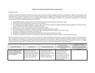
LAB 2<strong>Wireless</strong> <strong>Local</strong> <strong>Area</strong> <strong>Network</strong>Configure the <strong>Wireless</strong> Nodes1. Repeat the following for each of the nine nodes:Right-click on the node · Edit Attributes · Assign to the <strong>Wireless</strong> LAN MAC Addressattribute a value equals to the node number (e.g., address 1 is assigned to node_1) ·Assign to the Destination Address attribute the corresponding value shown in thefollowing table · Click OK .NodeNamenode_0node_1node_2node_3node_4node_5node_6node_7node_8DestinationAddressRandom5867134213a. The following figure shows the values assigned to the Destination Address and<strong>Wireless</strong> LAN MAC Address attributes for node_1.
<strong>Network</strong> Simulation Experiments ManualTraffic Generation Parameters1. Select all nodes in the network simultaneously except node_0 (click on all of them whileholding the Shift key) · Right-click on any of the selected nodes · Edit Attributes ·Check the Apply Changes to Selected Objects check box.2. Expand the Traffic Generation Parameters and the Packet Generation Arguments hierarchies· Edit the attributes to match the following figure · Click OK .Buffer Size specifi esthe maximum size of thehigher-layer data bufferin bits. Once the bufferlimit is reached, the datapackets arriving fromthe higher layer will bediscarded until somepackets are removedfrom the buffer so thatthe buffer has some freespace to store these newpackets.143. Select all nodes in the network simultaneously, includingnode_0 · Right-click on any of the selected nodes ·Edit Attributes · Check the Apply Changes to SelectedObjects check box.4. Expand the hierarchy of the <strong>Wireless</strong> LAN Parametersattribute · Assign the value 4608000 to the Buffer Size(bits) attribute · Click OK .5. Right-click on node_0 · Edit Attributes · Expand the<strong>Wireless</strong> LAN Parameters hierarchy and set the AccessPoint Functionality to Enabled · Click OK .6. Save the project.Choose the StatisticsTo test the performance of the network in our DCF scenario, wewill collect some of the available statistics as follows:1. Right-click anywhere in the project workspace andselect Choose Individual Statistics from the pop-upmenu.2. In the Choose Results dialog box, expand the GlobalStatistics and Node Statistics hierarchies · Choosethe five statistics shown.3. Click OK.Configure the SimulationHere we will configure the simulation parameters:1. Click on and the Configure Simulation windowshould appear.2. Set the duration to be 10.0 minutes .3. Click OK and then Save your project.
LAB 2<strong>Wireless</strong> <strong>Local</strong> <strong>Area</strong> <strong>Network</strong>Duplicate the ScenarioIn the network we just created, we did not utilize many of the features explained in theoverview section. By default, the distributed coordination function (DCF) method is usedfor the Medium Access Control (MAC) sublayer. We will create three more scenarios toutilize the features available from the IEEE 802.11 standard. In the DCF_Frag scenario,we will allow fragmentation of the MAC data units into smaller frames and test its effecton the network performance. The DCF_PCF scenario utilizes the point coordinationfunction (PCF) method for the MAC sublayer along with the DCF method. Finally, in theDCF_PCF_Frag scenario we will allow fragmentation of the MAC data and check its effectalong with PCF.THE DCF_FRAG SCENARIO1. Select Duplicate Scenario from the Scenarios menu and give it the name DCF_Frag ·Click OK .2. Select all the nodes in the DCF_ Frag scenario simultaneously · Right-click on anyone of them · Edit Attributes · Check the Apply Changes to Selected Objectscheck box.3. Expand the hierarchy of the <strong>Wireless</strong> LAN Parameters attribute · Assign the value 256to the Fragmentation Threshold (bytes) attribute · Click OK .FragmentationThreshold specifi es thefragmentation thresholdin bytes. Any data packetreceived from a higherlayer with a size greaterthan this threshold willbe divided into fragments,which will betransmitted separatelyover the radio interface.Regardless of the valueof this attribute, if thesize of a higher-layerpacket is larger thanthe maximum MSDUsize allowed by the IEEE802.11 WLAN standard,which is 2304 bytes,then such a packet willnot be transmitted bythe MAC, and it will beimmediately discardedwhen received.154. Right-click on node_0 · Edit Attributes · Expand the <strong>Wireless</strong> LAN Parameters hierarchyand set the Access Point Functionality to Enabled · Click OK .THE DCF_PCF SCENARIO1. Switch to the DCF scenario, s elect Duplicate Scenario from the Scenarios menu andgive it the name DCF_PCF · Click OK · Save your project.2. Select node_0 , node_1 , node_3 , node_5 , and node_7 in the DCF_PCF scenario simultaneously(click on these nodes while holding the Shift key) · Right-click on any one ofthe selected nodes · Edit Attributes .3. Check Apply Changes to Selected Objects · Expand the hierarchy of the <strong>Wireless</strong> LANParameters attribute · Expand the hierarchy of the PCF Parameters attribute · Enablethe PCF Functionality attribute · Click OK .To switch to a scenario,choose Switch toScenario from theScenarios menu or justpress Ctrl+ .
<strong>Network</strong> Simulation Experiments Manual4. Right-click on node_0 · Edit Attributes · Expand the <strong>Wireless</strong> LAN Parameters hierarchyand set the Access Point Functionality to Enabled · Click OK .16THE DCF_PCF_FRAG SCENARIO1. Switch to the DCF_Frag scenario, s elect Duplicate Scenario from the Scenarios menuand give it the name DCF_PCF_Frag · Click OK · Save your project.2. Select node_0 , node_1 , node_3 , node_5 , and node_7 in the DCF_PCF_Frag scenariosimultaneously · Right-click on any one of the selected nodes · Edit Attributes .3. Check Apply Changes to Selected Objects · Expand the hierarchy of the <strong>Wireless</strong> LANParameters attribute · Expand the hierarchy of the PCF Parameters attribute · Enablethe PCF Functionality attribute · Click OK .4. Right-click on node_0 · Edit Attributes · Expand the <strong>Wireless</strong> LAN Parameters hierarchyand set the Access Point Functionality to Enabled · Click OK .Run the SimulationTo run the simulation for the four scenarios simultaneously:1. Go to the Scenarios menu · Select Manage Scenarios .2. Click on the row of each scenario and click the Collect Results button. This shouldchange the values under the Results column to as shown.
LAB 2<strong>Wireless</strong> <strong>Local</strong> <strong>Area</strong> <strong>Network</strong>5. Go to the Compare Results dialog box · Expand the Object Statistics hierarchy · Expandthe Office <strong>Network</strong> hierarchy · Expand the hierarchy of two nodes. One node shouldhave PCF enabled in the DCF_PCF scenario (e.g., node_3) and the other node shouldhave PCF disabled (e.g., node_2) · Show the result of the Delay (sec) statistic for thechosen nodes. The resulting graphs should resemble the following ones.6. Repeat Step 5 above but for the Retransmission Attempts (packets) statistic. The resultinggraphs should resemble the following ones.197. Close all graphs and the Compare Results dialog box · Save your project.FURTHER READINGANSI/IEEE Standard 802.11, 1999 Edition: <strong>Wireless</strong> LAN Medium Access Control (MAC) andPhysical Layer (PHY) Specifications.