Modification and tuning of diesel bus engine for biogas electricity ...
Modification and tuning of diesel bus engine for biogas electricity ...
Modification and tuning of diesel bus engine for biogas electricity ...

You also want an ePaper? Increase the reach of your titles
YUMPU automatically turns print PDFs into web optimized ePapers that Google loves.
Mj. Int. J. Sci. Tech. 2007, 01(2), 194-207Full PaperMaejo InternationalJournal <strong>of</strong> Science <strong>and</strong> TechnologyISSN 1905-7873Available online at www.mijst.mju.ac.th<strong>Modification</strong> <strong>and</strong> <strong>tuning</strong> <strong>of</strong> <strong>diesel</strong> <strong>bus</strong> <strong>engine</strong> <strong>for</strong> <strong>biogas</strong><strong>electricity</strong> productionSittiboon Siripornakarachai * <strong>and</strong> Thawan SucharitakulDepartment <strong>of</strong> Mechanical Engineering, Faculty <strong>of</strong> Engineering, Chiang Mai University,Chiang Mai 50200, Thail<strong>and</strong>* Corresponding author, e-mail : siripornakarachai@yahoo.com <strong>and</strong> thawan@dome.eng.cmu.ac.thReceived: 19 September 2007 / Accepted: 2 November 2007 / Published: 9 November 2007Abstract: This study is to convert <strong>and</strong> tune a <strong>bus</strong> <strong>diesel</strong> <strong>engine</strong> <strong>for</strong> <strong>electricity</strong> production ina farm using <strong>biogas</strong> as fuel. The <strong>engine</strong> under study was a Hino K-13CTI 13,000cc 24 valveturbocharged <strong>engine</strong> coupled to a 3-phase 4-pole induction motor to produce <strong>electricity</strong> at50 Hz. <strong>Modification</strong>s included an addition <strong>of</strong> <strong>biogas</strong> carburettor <strong>for</strong> air-fuel mixing,replacing the fuel injection system with spark ignition system, reduction <strong>of</strong> compressionratio from the original 16:1 to 8:1 using a cylinder head spacer, <strong>and</strong> modification <strong>of</strong> theturbocharger waste gate so the boost pressure can be adjusted. When the induction motorwas synchronised to the power grid, the running speed <strong>of</strong> the <strong>engine</strong> was 1,500 rpm.Optimal <strong>engine</strong> efficiency was achieved at 28.6% by setting the lambda factor at 1.097,ignition timing at 54 o be<strong>for</strong>e top dead center, <strong>and</strong> the turbocharger boost at 56 kPa. With thissetting, the generator power output was 134.20 kilowatt with emission <strong>of</strong> CO <strong>and</strong> NO Xbeing 1,154 <strong>and</strong> 896 ppm respectively.Keywords: modification <strong>engine</strong>, <strong>engine</strong> <strong>for</strong> <strong>electricity</strong>, <strong>biogas</strong> <strong>engine</strong>, <strong>engine</strong> <strong>for</strong> <strong>biogas</strong>, gas<strong>engine</strong>sIntroductionBiogas is a by-product <strong>of</strong> waste treatment in animal farms <strong>and</strong> can be used to replace fossil fuel toproduce electrical energy. Biogas is <strong>for</strong>med by digestion <strong>of</strong> animal waste by anaerobic bacteria <strong>and</strong> theapproximate composition is 60-80% methane, 20-40% carbon dioxide, <strong>and</strong> about 1% hydrogen sulfide
Mj. Int. J. Sci. Tech. 2007, 01(2), 194-207 195<strong>and</strong> other trace gases. Biogas has a liquefying pressure <strong>of</strong> 200-300 bar <strong>and</strong> a heating value <strong>of</strong> about23,400 kJ/m 3 [1,2]. The gas density is 1.2 kg/m 3 <strong>and</strong> has research octane number (RON) <strong>of</strong> about 130[2,3]. From the above properties, it can be seen that it is difficult to liquefy <strong>biogas</strong> <strong>for</strong> storage ortransport <strong>and</strong> it is quite suitable to be used as fuel in an internal com<strong>bus</strong>tion <strong>engine</strong> [4,5]. Statistics as<strong>of</strong> 2006 shows that in Thail<strong>and</strong> there are pig farms which have <strong>biogas</strong> waste treatment system that canproduce <strong>biogas</strong> totalling 35,000,000 cubic metres per year. If all are used to produce <strong>electricity</strong>, thetotal energy <strong>of</strong> 35,000,000 kilowatt-hour can be produced per year [6]. With an increase in <strong>biogas</strong>production towards larger quantities, such technical utilisation as the trans<strong>for</strong>mation into mechanicalenergy becomes an issue to be researched on. While larger <strong>engine</strong>s specifically designed <strong>for</strong> gas are onthe market, smaller <strong>engine</strong>s modified from st<strong>and</strong>ard Otto or <strong>diesel</strong> <strong>engine</strong>s are seen to fill the gap <strong>for</strong>small-to-medium <strong>and</strong> decentralised applications. Indian [7,8], Chinese [9], <strong>and</strong> French [10]publications mainly dealt with the modification <strong>of</strong> small stationary <strong>diesel</strong> <strong>engine</strong>s <strong>for</strong> dual fueloperation. Others went on to modify medium-sized <strong>diesel</strong> <strong>engine</strong>s including their governors [11], orresearched on the per<strong>for</strong>mance parameters <strong>of</strong> dual fuel <strong>biogas</strong> <strong>engine</strong>s in more detail [12].In Thail<strong>and</strong>, the <strong>bus</strong> is an expensive commodity compared to per capita income. As a result, <strong>bus</strong>esare kept running long beyond its life expectancy set by the manufacturer. To keep these <strong>bus</strong>es running,skilled mechanics as well as used <strong>engine</strong> markets <strong>and</strong> spare parts are well developed in Thail<strong>and</strong>. Aused <strong>bus</strong> <strong>engine</strong> imported from Japan in a reasonably good condition can be had <strong>for</strong> about 5,500 USdollars. The cost <strong>for</strong> <strong>engine</strong> overhaul after about 1,000,000 kilometers <strong>of</strong> use is about 1,400 US dollars.With a used <strong>bus</strong> <strong>engine</strong> coupled to an electrical generator, a farm owner can make a 130 kilowattpower generator fueled by <strong>biogas</strong> <strong>for</strong> about 23,100 US dollars <strong>and</strong> the break-even <strong>of</strong> the investmentcan be as short as one year. These <strong>engine</strong>s do not use a proper gas carburettor <strong>and</strong> are seldom tuned <strong>for</strong>best efficiency or low pollution [13]. This project is to investigate the proper adaptation <strong>of</strong> <strong>engine</strong> <strong>for</strong>durability <strong>and</strong> tune it <strong>for</strong> high efficiency <strong>and</strong> low emission.Just about any <strong>engine</strong> can be converted to run on <strong>biogas</strong> <strong>and</strong> produce <strong>electricity</strong> in a farm. Smaller<strong>engine</strong>s (under 5,000 cc capacity) are normally designed to per<strong>for</strong>m best at higher <strong>engine</strong> speed <strong>and</strong>are normally not designed <strong>for</strong> full capacity output like those required in electrical power production[14]. On the other h<strong>and</strong>, larger <strong>engine</strong>s like those found in heavy trucks or large <strong>bus</strong>es are designed tocarry a full load <strong>for</strong> most <strong>of</strong> its operating cycle <strong>and</strong> are also designed to run at lower <strong>engine</strong> speed. Asa result, car <strong>engine</strong>s will last about 150,000 kilometers between overhauls while <strong>bus</strong>es <strong>and</strong> large trucks<strong>engine</strong>s are expected to last more than 1,000,000 kilometers between overhauls. The long operatinglife <strong>of</strong> large <strong>engine</strong> makes it more suitable <strong>for</strong> <strong>electricity</strong> production in a farm <strong>and</strong> will probably costless in the long run to operate [13].Few variables need to be considered be<strong>for</strong>e the attempted adaptation <strong>of</strong> a <strong>diesel</strong> <strong>engine</strong> <strong>for</strong><strong>electricity</strong> production. First consideration is given to the overall <strong>engine</strong> design itself. The <strong>engine</strong> willneed to run at the generator synchronization speed to work as a generator. In this case, the generatorrequires the <strong>engine</strong> speed <strong>of</strong> 1,500 rpm <strong>for</strong> a four-pole generator <strong>and</strong> 3,000 rpm <strong>for</strong> a two-polegenerator. The <strong>bus</strong> <strong>engine</strong> under consideration provides maximum torque at 1,500 rpm so it is suitable<strong>for</strong> the 1,500 rpm running speed. Another variable to be considered is the feasibility <strong>of</strong> reducing thecompression ratio down to the spark ignition range. An overhead camshaft <strong>engine</strong> would be easy toadapt but the <strong>engine</strong> under consideration can also be adapted if the valve pushrod can be extended toaccommodate the additional distance between the camshaft <strong>and</strong> the rocker arm, due to the thickness <strong>of</strong>
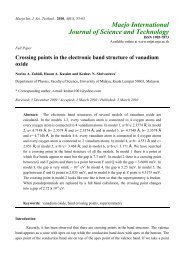
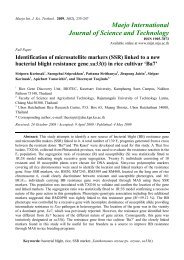
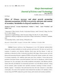
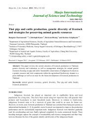
Mj. Int. J. Sci. Tech. 2007, 01(2), 194-207 196the cylinder head spacer. The space issue when replacing the fuel injectors with spark plugs also needsto be considered be<strong>for</strong>e the adaptation.This study aims to adapt a large <strong>diesel</strong> <strong>engine</strong> to run on <strong>biogas</strong> only <strong>and</strong> the adaptation involves anaddition <strong>of</strong> <strong>biogas</strong> carburettor <strong>for</strong> air-fuel mixing, replacing the fuel injection system with sparkignition system, reducing the compression ratio to suit <strong>biogas</strong> fuel using a cylinder head spacer, <strong>and</strong>modification <strong>of</strong> the turbocharger waste gate so the boost pressure can be adjusted. The test rig used aHino K-13CTI 13,000cc 24 valve turbocharged <strong>engine</strong> coupled to a 3-phase 4-pole induction motor toproduce <strong>electricity</strong> at 50 Hz. The <strong>engine</strong> was then tuned by changing air/fuel ratio, ignition timing, <strong>and</strong>turbocharger boost pressure to obtain the optimal running condition.Materials <strong>and</strong> MethodsThe Hino K-13CTI <strong>engine</strong> being studied was a turbocharged <strong>bus</strong> <strong>diesel</strong> <strong>engine</strong> that came with a fuelinjection system as well as a high compression ratio <strong>of</strong> 16:1 <strong>and</strong> a fixed waste gate boost control. For<strong>biogas</strong> fuel adaptation, a <strong>biogas</strong> carburettor was designed, manufactured, <strong>and</strong> installed. The fuelinjection system was replaced with a spark ignition system, the compression ratio was reduced to 8:1,<strong>and</strong> the waste gate was modified so the boost pressure could be adjusted. Each <strong>of</strong> these modificationsis discussed in turn in the following section <strong>of</strong> the paper.Carburettor designThe <strong>biogas</strong> carburettor designed <strong>and</strong> installed in this study is shown in Figure 1. A literature surveyshows that a suitable carburettor <strong>for</strong> a <strong>biogas</strong> <strong>engine</strong> should be a venturi with the accelerator conebeing tapered as a curve <strong>of</strong> 40 mm radius <strong>and</strong> the diffuser cone angle <strong>of</strong> 10 o . The <strong>biogas</strong> is fed into theventuri through multiple circular ports around the throat area <strong>and</strong> the throat air velocity should bebetween 100 to 150 meters/second [2]. With this in<strong>for</strong>mation, a carburettor designed <strong>for</strong> the 13,00cc<strong>engine</strong> operating at 1,500 rpm should have the throat diameter <strong>of</strong> 7.5 mm. The metering needle <strong>for</strong> thegas inlet was fabricated with a square root pr<strong>of</strong>ile to provide some linearity between the needleposition <strong>and</strong> the gas flow rate. The venturi was machined from aluminum stock <strong>and</strong> the carburettorbody was fabricated from PVC pipe parts.Spark ignitionThe distributor <strong>and</strong> ignition coil was adapted from the one used in 6-cylinder Toyota 5-ME <strong>engine</strong>.The vacuum <strong>and</strong> centrifugal advance was disabled because the <strong>engine</strong> would run at a constant speed<strong>and</strong> a full load when used to drive the generator. The distributor was driven by the original fuelinjection distributor mechanism. The fuel injection nozzle in the cylinder head was removed <strong>and</strong>replaced with a spark plug <strong>and</strong> an appropriate guide tube. The spark plug modification detail is shownin Figure 2.
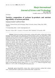
Mj. Int. J. Sci. Tech. 2007, 01(2), 194-207 197AirBiogas inletGas mixer outletFigure 1. Biogas carburettor design: (1) Venturi housing, (2) Venturi base, (3) Venturi mixer,(4) Metering housing, (5) Main jet, (6) Metering adjusting nut spacer, (7) Metering adjustingnut, (8) Metering needle, (9) Metering adjusting screw, (10) Return spring, <strong>and</strong> (11) Pipejunction218657121110653 434(A) Be<strong>for</strong>e modification129(B) After modificationFigure 2. Cutaway view <strong>of</strong> the modified cylinder head: (1) Valve cover, (2) Cylinder head,(3) Intake port, (4) Exhaust port, (5) Valve guide, (6) Exhaust valve, (7) Diesel injectionnozzle guide, (8) Diesel injection nozzle, (9) Spark plug guide, (10) Middle spark plug rodguide, (11) Upper spark plug rod guide, <strong>and</strong> (12) Spark plug
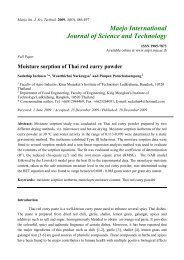
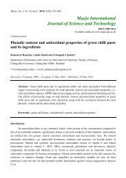
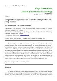
Mj. Int. J. Sci. Tech. 2007, 01(2), 194-207 199Test <strong>engine</strong>The test <strong>engine</strong> was a Hino 13,000cc <strong>diesel</strong> <strong>engine</strong> with 4 valves per cylinder, modified <strong>for</strong> <strong>biogas</strong>fuel as described above. The <strong>engine</strong> model was K-13CTI <strong>and</strong> was normally installed in <strong>bus</strong>es inThail<strong>and</strong>. This <strong>engine</strong> was chosen because <strong>of</strong> used <strong>engine</strong> availability <strong>and</strong> commonly available spareparts. It was overhauled to new <strong>engine</strong> specification be<strong>for</strong>e testing <strong>and</strong> is currently undergoingendurance test at 4T farm, Chiang Mai, Thail<strong>and</strong>.Electrical generator unitThe generator used was a 3-phase 4-pole 132-kW generator with an induction motor made byHASCON, model number 200L2-2. The generator was directly coupled by a clutch mechanism to thetest <strong>engine</strong> <strong>and</strong> was synchronised to the power grid when in operation. The nominal operating speedwas 1,500 rpm.Biogas mainGas meterTemperature meterBall valveTemperature meterAir mainGas meterAir filterSafety & Control unitCooling water, Gasmixer & Oil lubricantIntercoolerThree phaseinduction motorFour stroke <strong>engine</strong>with spark ignitionAir flowCrank angle signalMonitorAdjustable waste gatePressure gageCarburettorCO, O 2 , NO X emissionanalyzer & Exhaust gastemperature meterTurbochargerFigure 4. Block diagram <strong>of</strong> the test rig
Mj. Int. J. Sci. Tech. 2007, 01(2), 194-207 200Control unitBiogas Advisory Unit, Chiang Mai University, designed the control unit <strong>and</strong> the blueprint wasavailable to the public at no cost. It was used to start the test <strong>engine</strong>, synchronise the generator with thepower grid, as well as monitor safety function in the case <strong>of</strong> gas supply shortage, short circuit,overloading in power grid, <strong>engine</strong> overheating, loss <strong>of</strong> oil pressure in the <strong>engine</strong>, or power grid failure.Intake air measurementIntake air flow rate was measured using a Kobold gas flow meter model GVPA-303-GDR.Intake <strong>biogas</strong> measurementThe composition <strong>of</strong> inlet <strong>biogas</strong> varies with the type <strong>of</strong> animal waste used to produce the gas as wellas the ambient temperature in which the fermentation occurs. In general, <strong>biogas</strong> contains carbondioxide, methane <strong>and</strong> one percent <strong>of</strong> other trace gases. The methane content <strong>of</strong> <strong>biogas</strong> can bedetermined by finding the amount <strong>of</strong> carbon dioxide, adding 1 percent to the amount <strong>and</strong> subtractingthis from 100, thus yielding the percentage by volume <strong>of</strong> methane. The amount <strong>of</strong> carbon dioxide inthe <strong>biogas</strong> was determined by using the Brigon IND 60 gas analyser. The volume flow rate <strong>of</strong> <strong>biogas</strong>was measured using a Kobold gas flow meter model GVPA-303-GDR.Exhaust gas measurementA flue gas analyser (Testo 300XL-1) was used to monitor the quantity <strong>of</strong> O 2 , CO, <strong>and</strong> NO X in theexhaust gas. The probe attached could also measure the exhaust gas temperature as well.Ignition timing measurementIgnition timing was measured by a timing light (Sincro model DG86) with trigger signal from thehigh tension wire from the distributor to cylinder number one spark plug.Power output measurementThe power output from the generator was monitored by Curcutor model AR5 supply networkanalyser.Experimental ProcedureThe experiment was carried out using the following steps to collect data <strong>for</strong> analysis.Turbocharger pressure adjustmentThe <strong>engine</strong> was run on <strong>biogas</strong> with RON <strong>of</strong> about 130. To get the most benefit from the higherRON, higher compression ratio was used <strong>for</strong> higher thermal efficiency [15-18]. The propercompression ratio <strong>for</strong> the spark ignition <strong>engine</strong> to be run on <strong>biogas</strong> fuel was between 10 to 12:1 [2].
Mj. Int. J. Sci. Tech. 2007, 01(2), 194-207 201While a naturally aspirated spark ignition <strong>engine</strong> may have sufficient margin <strong>of</strong> safety relative toknock to allow modest inlet-air boost, any substantial air compression prior to cylinder entry willrequire changes in <strong>engine</strong> design <strong>and</strong>/or operating variables to <strong>of</strong>fset the negative impact on knock.The variables which were adjusted to control knock in a turbocharged SI <strong>engine</strong> were: compressionratio, spark retard from optimum, charge air temperature, <strong>and</strong> air/fuel equivalence ratio [18]. There<strong>for</strong>ethe cylinder head was installed with a spacer to increase the com<strong>bus</strong>tion chamber volume <strong>and</strong> producelower compression ratio. The experiment would start at the compression ratio <strong>of</strong> 8:1 <strong>and</strong> theturbocharger pressure was adjusted by the waste gate at 40 kPa <strong>and</strong> increased at an increment <strong>of</strong> 4 kPauntil <strong>engine</strong> efficiency began to decrease.Initial air/fuel mixture adjustmentThe <strong>engine</strong> was started, the ignition timing was set at about mid range (55 o BTDC) <strong>and</strong> the air/fuelmixture screw (metering adjustment screw in the carburetor) was adjusted to the position that the<strong>engine</strong> just ran smoothly (lean mixture).Initial ignition timing adjustmentThe ignition timing was set at 50 o BTDC at the beginning <strong>of</strong> a data collection.Data collectionThe recording <strong>of</strong> the following set <strong>of</strong> data was per<strong>for</strong>med: air temperature, <strong>biogas</strong> temperaturebe<strong>for</strong>e <strong>and</strong> after boost by turbocharger <strong>and</strong> after cooling by intercooler, <strong>engine</strong> coolant temperature,lubricating oil temperature, exhaust gas temperature, air <strong>and</strong> <strong>biogas</strong> consumption rate, ignition timing,generator power output, oxygen remaining after com<strong>bus</strong>tion, carbon monoxide <strong>and</strong> oxide <strong>of</strong> nitrogenin the exhaust gas.Ignition timing incrementThe ignition timing was advanced 2 o <strong>and</strong> the data above were again collected. The process wasrepeated until the ignition timing reached 60 o BTDC or excessive pre-ignition was observed.Air/fuel mixture incrementAfter a set <strong>of</strong> data was collected, the air/fuel mixture screw was turned half a revolution in the richdirection. Another set <strong>of</strong> data was collected <strong>and</strong> the process was repeated until the mixture was too rich<strong>for</strong> the <strong>engine</strong> to run smoothly.ResultsThe collected data were processed into excess air ratio (λ), <strong>engine</strong> efficiency, <strong>and</strong> then the systemefficiency (overall efficiency), power output, exhaust gas temperature, specific <strong>biogas</strong> consumption,
Mj. Int. J. Sci. Tech. 2007, 01(2), 194-207 202oxygen quantity in exhaust gas, carbon monoxide <strong>and</strong> oxide <strong>of</strong> nitrogen emission were plotted againstthe ignition timing, excess air ratio, <strong>and</strong> turbocharger pressure. The resulting graphs are shown inFigures 5-7.Exhaust gas temperature;T fg (oC)Actual Electric Power Output (kW)Specific Biogas Consumption (m3/kWh)Engine efficiency (%)Carbon monoxide;CO (ppm)Oxygen;O2 (%)Figure 5. Exhaust gas temperature, electric power output, specific <strong>biogas</strong> consumption, <strong>engine</strong>efficiency, carbon monoxide, <strong>and</strong> oxygen <strong>for</strong> compression ratio <strong>of</strong> 8:1 <strong>and</strong> turbochargerpressure setting at 56 kPa plotted against: (A) Ignition timing, <strong>and</strong> (B) Excess air ratio.
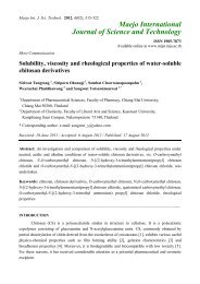
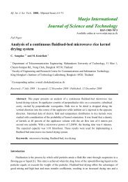
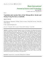
Mj. Int. J. Sci. Tech. 2007, 01(2), 194-207 203Turbocharger pressure (kPa)45003040 44 48 52 56 60 64 681503000Oxide <strong>of</strong> nitrogen; NO X (ppm)4000350030002500200015001000500Engine efficiency (%)28262422Engine efficiencyActual electric powerCarbon monoxide140130120110100Actual electric power output (kW)2500200015001000500Carbon monoxide; CO (ppm)020Oxide <strong>of</strong> nitrogen900Figure 6. Output power, <strong>engine</strong> efficiency, carbon monoxide <strong>and</strong> oxide <strong>of</strong> nitrogen plotted againstturbocharger boost pressure.DiscussionEffect <strong>of</strong> Ignition Timing on Engine Per<strong>for</strong>manceFrom Figure 5(A) it can be seen that the maximum <strong>engine</strong> efficiency <strong>and</strong> maximum output powercan be achieved at 54 o BTDC ignition timing. When the timing is retarded from the optimal setting,the com<strong>bus</strong>tion process is completed after the bottom dead center position <strong>of</strong> the crankshaft <strong>and</strong> thethermal energy transferred to shaft power is reduced. The result is higher exhaust gas temperature asshown in the graph. If the ignition timing is advanced beyond the optimal point, knocking occurs,resulting in excessive com<strong>bus</strong>tion temperature <strong>and</strong> increase in NO X <strong>and</strong> CO emission.Effect <strong>of</strong> Air/Fuel Mixture on Engine Per<strong>for</strong>manceFigure 5(B) shows that the optimal excess air ratio <strong>for</strong> this <strong>engine</strong> is 1.097. Leaner mixture resultsin lower flame speed <strong>and</strong> incomplete com<strong>bus</strong>tion, which leads to high exhaust gas temperature. Richmixture can lead to <strong>engine</strong> knock <strong>and</strong> results in higher NO X <strong>and</strong> CO emission as well as high exhausttemperature.Effect <strong>of</strong> Turbocharger Boost Pressure on Engine Per<strong>for</strong>manceFigures 6 <strong>and</strong> 7 show that the increase in turbocharger boost pressure can increase the <strong>engine</strong> outputeven though the <strong>engine</strong> efficiency has dropped <strong>of</strong>f at higher boost pressure. Increasing the boostpressure beyond the maximum efficiency point results in high CO <strong>and</strong> NO X emission as well asexcessive <strong>engine</strong> vibration <strong>and</strong> it appears that the increased <strong>engine</strong> output is not worth the increasedpollution <strong>and</strong> shortened <strong>engine</strong> life due to vibration.
Mj. Int. J. Sci. Tech. 2007, 01(2), 194-207 204(A)Electric power output (kW)(B)Engine efficiency (%)Figure 7. Power output (A) <strong>and</strong> <strong>engine</strong> efficiency (B) plotted against excess air ratio <strong>and</strong>turbocharger pressure at compression ratio <strong>of</strong> 8:1
Mj. Int. J. Sci. Tech. 2007, 01(2), 194-207 205Three categories <strong>of</strong> <strong>tuning</strong> optimisation were done. The categories are lowest CO emission, highest<strong>engine</strong> efficiency, <strong>and</strong> highest power output. The <strong>tuning</strong> parameters <strong>and</strong> collected data <strong>for</strong> the threecategories are presented in Table 1.With the presented data, it can be shown that a large <strong>diesel</strong> <strong>engine</strong> can be economically adapted <strong>for</strong>power generation in a farm. The payback period is less than one year <strong>and</strong> when properly tuned, the<strong>engine</strong> passes the internationally accepted pollution control st<strong>and</strong>ard <strong>of</strong> carbon monoxide <strong>of</strong> a vehicle<strong>engine</strong> [19, 20].Table 1. Summarised data <strong>of</strong> fine <strong>tuning</strong> <strong>of</strong> <strong>biogas</strong> <strong>engine</strong> <strong>for</strong> optimum operation when compressionratio is 8:1 <strong>and</strong> turbocharger boost pressure is 56 kPaItemLowest COemissionHighest <strong>engine</strong>efficiencyHighestpower output1. Optimum ignition timing ( o BTDC) 57 54 522. Excess air ratio; λ 1.215 1.097 0.9893. Fuel consumption; f C (m 3 /hr) 71.80 78.60 86.104. Specific fuel consumption; sfc (m 3 /kWh) 0.64 0.59 0.615. Actual electric power output; P EL (kW) 111.40 134.20 140.706. Engine efficiency; η eng (%) 26.01 28.63 27.407. Overall efficiency; η tot (%) 23.41 25.76 24.668. Oxide <strong>of</strong> nitrogen emission; NO X (ppm) 511 896 8439. Carbon monoxide emission; CO (ppm) 854 1,154 2,57610. Oxygen in exhaust gas; O 2 (%) 10.00 6.20 5.9011. Engine coolant temperature; T eng ( o C) 88.2 88.7 89.012. Lubricating oil temperature; T oil ( o C) 87.8 87.2 87.613. Exhaust gas temperature; T fg ( o C) 536.0 521.5 533.814. Payback period (year) 0.78 0.52 0.49ConclusionIn this study, <strong>engine</strong> per<strong>for</strong>mance <strong>and</strong> pollution figures are recorded <strong>for</strong> a range <strong>of</strong> <strong>engine</strong> <strong>tuning</strong>parameters, viz. turbocharger boost, ignition timing <strong>and</strong> excess air ratio. The compression ratio was setat 8:1 <strong>and</strong> the turbocharger boost was varied by adjusting the waste gate. When the system wasoperating at 1,500 rpm, the range <strong>of</strong> <strong>engine</strong> setting was as follows: excess air ratio between 0.9 to 1.2,ignition timing between 50 o to 60 o be<strong>for</strong>e top dead center, <strong>and</strong> turbocharger pressure setting between40 to 68 kPa. Under these operating conditions, the <strong>engine</strong> efficiency increased as the boost wasincreased from 40 to 56 kPa <strong>and</strong> there was a slight increase <strong>of</strong> NO X <strong>and</strong> CO as the boost went up. Asthe boost was increased from 56 kPa to 68 kPa, the <strong>engine</strong> efficiency began to decrease <strong>and</strong> theamount <strong>of</strong> pollution was increased. Increase in <strong>engine</strong> vibration was also noted in this turbochargerboost range. Oxide <strong>of</strong> nitrogen (NO X ) was high when high pressure <strong>and</strong> temperature occurred in thecom<strong>bus</strong>tion. A test showed that more power can be generated if the <strong>engine</strong> is operated with rich excess
Mj. Int. J. Sci. Tech. 2007, 01(2), 194-207 206air ratio <strong>and</strong> high turbocharger boost. Higher <strong>engine</strong> output will yield shorter payback period <strong>for</strong> theinvestment but increasing the boost pressure beyond 56 kPa will cause excessive pollution emission<strong>and</strong> <strong>engine</strong> vibration, which will probably shorten the <strong>engine</strong> life. It can be concluded that the boostpressure <strong>of</strong> 56 kPa yields the highest efficiency with acceptable pollution level <strong>for</strong> this <strong>engine</strong>.AcknowledgementsThe work presented in this research would not have been possible without the invaluable supportfrom many people. First <strong>and</strong> <strong>for</strong>emost, the authors would like to gratefully acknowledge materialassistance from the Mechanical Engineering Department <strong>of</strong> Chiang Mai University <strong>and</strong> also fromBiogas Technology Center (BTC). 4T Farm Chiang Mai is cordially thanked <strong>for</strong> permission to use thelocation <strong>and</strong> <strong>biogas</strong> to finish the research.Last <strong>and</strong> most importantly, we would like to thank the Energy Policy <strong>and</strong> Planning Office (EPPO),Thail<strong>and</strong> <strong>for</strong> financial support.References1. U. Werner, U. Stoehr, <strong>and</strong> N. Hees, “A H<strong>and</strong>book <strong>of</strong> Biogas Plants in Animal Husb<strong>and</strong>ry; APractical Guid in Deutsche Gesellschaft fuer Technische Zusammenarbeit (GTZ)”, Friedr. Vieweg& Sohn, Verlagsgesellschaft mbH, 1988.2. K. von Mitzlaff, “A H<strong>and</strong>book <strong>of</strong> Engine <strong>for</strong> Biogas; Theory, <strong>Modification</strong>, Econum, Operation”,Friedr. Vieweg & Sohn, Verlagsgesellschaft mbH, 1988.3. G. Sridhar, P. J. Paul, <strong>and</strong> H. S. Mukunda, “Biomass derived producer gas as a reciprocating<strong>engine</strong> fuel, an experimental analysis”, J. Biomass <strong>and</strong> Bioenergy, 2001, 21, 61−72.4. J. L. King <strong>and</strong> T. Mintner, “Biogas-driven generator set”, US Patent, Patent Number: 5,724,948,Mar. 10, 1998.5. S. Siripornakarachai <strong>and</strong> T. Sucharitakul, “Adapting gasoline <strong>engine</strong> to <strong>biogas</strong> <strong>engine</strong> <strong>for</strong>electrical power generation”, J. Energy Word, 2007, 37, 34-36.6. N. Potikanond, “Use <strong>of</strong> animals dung from <strong>biogas</strong> reactor as fertilizer”, Project <strong>for</strong> Promotion <strong>of</strong>Biogas Production in Animals Farm (H<strong>and</strong>book), Biogas Advisory Unit (BAU), Chiang Mai,1995.7. M. K. K. Publ, “Kirloskar Dual Fuel Biogas Engines”, Commonwealth Regional (Asia/Pacific)Rural Technology Programme, Bombay, 1980.8. A. Henhem <strong>and</strong> M. K. Makkar, “Com<strong>bus</strong>tion <strong>of</strong> simulated <strong>biogas</strong> in a <strong>diesel</strong>-fuel <strong>diesel</strong> <strong>engine</strong>”,J. Sci., 1998, 39, 2001-2009.9. S. P. E. Persson <strong>and</strong> H. D. Bartlett, “Biogas <strong>engine</strong>s <strong>for</strong> agricultural motor-generators”, J. Amer.Soc. Agric. Eng. (ASAE), 1981, Paper Number: 811211.10. A. Bilican, O. L. Corre, <strong>and</strong> A. Delebarre, “Thermal efficiency <strong>and</strong> environmental per<strong>for</strong>mances<strong>of</strong> a <strong>biogas</strong>-<strong>diesel</strong> stationary <strong>engine</strong>”, J. Environ. Tech., 2003, 24, 1165-1173.11. J. O. Canavate, D. J. Hills, <strong>and</strong> W. J. Chancellor, “Diesel <strong>engine</strong> modification to operate on<strong>biogas</strong>.”, Transactions <strong>of</strong> the American Society <strong>of</strong> Agricultural Engineers (ASAE), 1981.
Mj. Int. J. Sci. Tech. 2007, 01(2), 194-207 20712. K. V. Mitzlaff <strong>and</strong> M. H. Mkumbwa, “Use <strong>of</strong> <strong>biogas</strong> as an alternative fuel in stationary <strong>diesel</strong><strong>engine</strong>s.”, Technical Report, University <strong>of</strong> Dar-es-Salaam, Tanzania, 1985.13. S. Siripornakarachai <strong>and</strong> T. Sucharitakul, “<strong>Modification</strong> <strong>of</strong> <strong>diesel</strong> <strong>engine</strong> <strong>for</strong> <strong>electricity</strong> productionfueled by <strong>biogas</strong>”, The 6 th Asia Pacific Conference on Sustainable Energy <strong>and</strong> EnvironmentalTechnologies (APCSEET 2007), 7 - 11 May 2007, Bangkok, Thail<strong>and</strong>.14. S. Siripornakarachai <strong>and</strong> T. Sucharitakul, “Tuning <strong>of</strong> multi-valve automotive <strong>engine</strong> <strong>for</strong> <strong>electricity</strong>production fueled by <strong>biogas</strong>.”, International Conference on Green <strong>and</strong> Sustainable Innovation(ICGSI 2006), 29 November - 1 December 2006, Chiang Mai, Thail<strong>and</strong>.15. S. Siripornakarachai, “The result <strong>of</strong> worked as velocity <strong>of</strong> electrical power generator used by<strong>biogas</strong>”, J. Energy Word, 2007, 36, 32-35.16. Hino Motors, Ltd., “A H<strong>and</strong>book <strong>of</strong> Industrial Engines”, Tokyo, 2005.17. J. Huang <strong>and</strong> R. J. Crookes, “Assessment <strong>of</strong> simulated <strong>biogas</strong> as a fuel <strong>for</strong> the spark ignition<strong>engine</strong>”, J. Sci., 1998, 77, 1793−1801.18. J. B. Heywood, “A Textbook <strong>of</strong> Internal Com<strong>bus</strong>tion Engine Fundamentals”, Int. Edn., McGraw-Hill, New York, 1988.19. Pollution Control Department in Ministry <strong>of</strong> Natural Resources <strong>and</strong> Environment, Bangkok,Thail<strong>and</strong>, “Law & Regulations <strong>of</strong> Air Quality <strong>and</strong> Noise St<strong>and</strong>ard”,http//www.pcd.go.th/info_serv/ reg_std_airsnd02.html, 1 November, 2007.20. United States Environmental Protection Agency (USEPA), “Law & Regulations <strong>of</strong> Air Pollution”,http//www.epa.gov/ebtpages/air.html, 1 November, 2007.© 2007 by Maejo University, San Sai, Chiang Mai, 50290 Thail<strong>and</strong>. Reproduction is permitted <strong>for</strong>noncommercial purposes.