Create successful ePaper yourself
Turn your PDF publications into a flip-book with our unique Google optimized e-Paper software.
Compact Modules <strong>CKK</strong>/C<strong>KR</strong> 9-70with Ball Screw Drive and Toothed Belt DriveThe Drive & Control Company
2 <strong>Bosch</strong> <strong>Rexroth</strong> <strong>Corp</strong>orationCompact Modules <strong>CKK</strong>/C<strong>KR</strong> 9-70 R310A 2624 (2009.05)Linear Motion and Assembly TechnologiesBall Rail SystemsRoller Rail SystemsLinear Bushings and ShaftsBall Screw DrivesLinear Motion SystemsBasic Mechanical ElementsManual Production SystemsTransfer Systemswww.boschrexroth-us.com
R310A 2624 (2009.05) Compact Modules <strong>CKK</strong>/C<strong>KR</strong> 9-70<strong>Bosch</strong> <strong>Rexroth</strong> <strong>Corp</strong>oration3<strong>CKK</strong>/C<strong>KR</strong> 9-70 Compact ModulesOverview of types with load capacities 4Product overview of motors and controllers 6Compact Modules with ball screw drive (<strong>CKK</strong>) 8Product Overview 8Structural design 10Technical data 12<strong>CKK</strong> 9-70 14Compact Modules with toothed belt drive (C<strong>KR</strong>) 18Product Overview 18Structural design 20Technical data 22C<strong>KR</strong> 9-70 24Performance data 28Switch mounting arrangements 30Overview of switching systems 30Magnetic fi eld sensor with plug 32Mounting 34Mounting, clamping fi xtures, centering ring 34Connecting shafts for Compact Modules C<strong>KR</strong> 35Connection plates for <strong>CKK</strong>/C<strong>KR</strong> 9-70 36Connection of Compact Modules via cross-plate 38Maintenance 39Lubrication 39Motors 40Servo motors 40Three-phase stepping motors 41Documentation 42Inquiry / Order form 43
4 <strong>Bosch</strong> <strong>Rexroth</strong> <strong>Corp</strong>oration Compact Modules <strong>CKK</strong>/C<strong>KR</strong> 9-70 R310A 2624 (2009.05)Overview of types with load capacitiesType designation (size)Compact Modules are identifi ed by thetype designation and size.The type designations are also assignedto the design styles with the sameexternal features but without drive unit.System = Compact Module (C)Guideway = Ball rail system (K)Typ eSizeC K K 9- 70Drive unit = Ball screw drive (K) orToothed belt drive (R)Guidewaydimension =ca. (mm)Framedimension =AType Guideway Drive unit Compact ModuleCompact Modules<strong>CKK</strong>Ball rail systemBall screw driveC<strong>KR</strong>Ball rail systemToothed belt drive
R310A 2624 (2009.05) Compact Modules <strong>CKK</strong>/C<strong>KR</strong> 9-70<strong>Bosch</strong> <strong>Rexroth</strong> <strong>Corp</strong>oration5HH1A<strong>CKK</strong>AC<strong>KR</strong>Dynamic load capacity C (N)Compact Module Dimensions A x H (mm) H 1 (mm) L max (mm)Short carriageLong carriage<strong>CKK</strong> 9-70 70 x 32 44.5 650 2360 3830C<strong>KR</strong> 9-70 70 x 32 44.5 1500 2360 3830Note: All Compact Modules are also available without a drive unit.
6 <strong>Bosch</strong> <strong>Rexroth</strong> <strong>Corp</strong>oration Compact Modules <strong>CKK</strong>/C<strong>KR</strong> 9-70 R310A 2624 (2009.05)Product overview of motors and controllersMotor selection based on drivecontrollers and control systemDigital AC servo motor MSKSeveral motor-controller combinationsare available in order to provide themost cost-effective solution for everycustomer application.When dimensioning the drive unit,always consider the motor-controllercombination.For more detailed information on motorsand control systems, please refer to thecatalogs “ECODRIVE Cs” and “IndraDrivefor Linear Motion Systems.”Digital AC servo motor MSMThree-phase stepping motor VRDM
HandRS232AutoR310A 2624 (2009.05) Compact Modules <strong>CKK</strong>/C<strong>KR</strong> 9-70<strong>Bosch</strong> <strong>Rexroth</strong> <strong>Corp</strong>oration7Digital controllersIndraDriveDigital controllersECODRIVE CsA complete solutionPower electronicsSD326SD328Compact Modules are available as completesolutions with motor, controller unit,and control system.Twin LineProfi Stepcontrol unit
8 <strong>Bosch</strong> <strong>Rexroth</strong> <strong>Corp</strong>oration Compact Modules <strong>CKK</strong>/C<strong>KR</strong> 9-70 R310A 2624 (2009.05)Compact Modules <strong>CKK</strong>Product OverviewCompact Modules are precision, ready-to-install linear motion systems characterizedby their high performance and compact design.Favorable price/performance ratio and fast delivery times.Structural design– Extremely compact precisionaluminum profi le (frame) with twointegrated ball rail systems– Precision ball screw drive accordingto tolerance grade 7 with backlashfreenut system– Fixed bearing end block made ofaluminum with two-row, preloadedangular-contact thrust ball bearing– Floating bearing end block withdouble ball bearings– Short or long carriage made ofaluminum with integrated runnerblocksAttachments– Maintenance-free digital AC servodrives with integrated brake andattached feedback or steppingmotors– Motor mount and coupling or timingbelt side drive for motor attachment– Switches– Socket with mating plug for theswitches– Mounting duct made of profi ledaluminumOther distinguishing features– Economical maintenance thanks to one-point lubrication feature (greaselubrication) of ball rail systems and ball screw drive at both sides– Easy motor attachment by means of locating feature and fastening threads– Precise alignment and secure fastening of attachments through threads andpin holes and through short or long carriage– Internal components protected by rigid aluminum cover and two gap-typeseals made of PU strip reinforced with integrated steel cords– Adjustable switches over the entire travel range, switch activation withoutswitching cam– Two integrated zero-clearance ball rail systems provide optimized travelperformance, high load capacities, and high rigidity– Exceptionally low profi le due to centrally located ball screw– High positioning accuracy and repeatability provided by ball screw drive withzero-backlash nut system– High travel speeds with simultaneous high precision over great lengths throughball rail systems, large screw diameters and screw leads, and double fl oatingbearingsDrive controllers and control systemsFor mounting and maintenance, see“Instructions for Compact Modules<strong>CKK</strong>” R310D4 2671
R310A 2624 (2009.05) Compact Modules <strong>CKK</strong>/C<strong>KR</strong> 9-70<strong>Bosch</strong> <strong>Rexroth</strong> <strong>Corp</strong>oration9Connection plate for easy installation
10 <strong>Bosch</strong> <strong>Rexroth</strong> <strong>Corp</strong>orationCompact Modules <strong>CKK</strong>/C<strong>KR</strong> 9-70 R310A 2624 (2009.05)Compact Module <strong>CKK</strong>Structural designStructural design <strong>CKK</strong>1 Ball screw drive with zero-backlash,cylindrical single nut2 Floating bearing end block3 Short carriage with two integratedrunner blocks3a Long carriage with four integratedrunner blocks4 Aluminum cover5 Gap-type seal made of PU strip(recirculating)6 Fixed bearing end block7 Frame2131043a59876Attachments:8 Magnetic fi eld sensor9 Mounting duct10 Socket/plug11 Connection plate3a1112 Motor13 Motor mount and coupling14 Timing belt side drive13121412
R310A 2624 (2009.05) Compact Modules <strong>CKK</strong>/C<strong>KR</strong> 9-70<strong>Bosch</strong> <strong>Rexroth</strong> <strong>Corp</strong>oration11Structural design of motormount and couplingA motor can be attached to all CompactModules with ball screw drive by means ofa motor mount and coupling.The motor mount serves to fasten the motorto the Compact Module and acts as aclosed housing for the coupling.The motor’s drive torque is transmittedstress-free through the coupling to theCompact Module’s drive shaft.Our standard couplings compensate thesystem’s thermal expansion.If installing third-party couplings, thermalexpansion must be considered.1 Motor2 Motor mount3 Coupling4 Compact ModuleStructural design of timing beltside driveAll Compact Modules offer the option ofattaching the motor via a timing belt sidedrive.This makes the overall length shorter thanwhen attaching the motor with a motormount and coupling.The compact, closed housing serves asprotection for the belt and as a motorbracket.Various gear ratios are also available:––i = 1 : 1i = 1 : 1.5F prThe timing belt side drive can beinstalled in four directions:– below, above (RV01 and RV02)– left, right (RV03 and RV04)1 Compact Module2 Drawn, anodized aluminum profi le3 Toothed belt4 AC servo motor5 Pre-tensioning the toothed belt:Apply pretensioning force F pr tomotor (F pr is provided upon delivery)6 Fastening of belt pulleys with tensioningunits7 Cover plate8 Cover
12 <strong>Bosch</strong> <strong>Rexroth</strong> <strong>Corp</strong>orationF y max stipulated.F y maxCompact Modules <strong>CKK</strong>/C<strong>KR</strong> 9-70 R310A 2624 (2009.05)Compact Module <strong>CKK</strong>Technical dataGeneral technical dataSize Carriage Ball Dynamic load capacity C (N) Dynamic Planar moment Maximum Moved mass ofscrewmoments of inertia length system m ca (kg)zyyzConnection plateGuidewayBall Fixed M t M L l y l z L max without withd 0 x Pscrew bearing (Nm) (Nm) (cm 4 ) (cm 4 ) (mm)<strong>CKK</strong> 9-70 short 8 x 2.5 2360 2200 1600 47 7 12.1 63.3 650 0.15 0.26long 3830 76 111 0.25 0.42Size Carriage Maximum permissible forces (N) Maximum permissible moments (Nm) Weight with ball screw (kg)F z1 max F z2 max F y max M x max M y max , M z max<strong>CKK</strong> 9-70 short 1180 1180 590 23 7 3.16 ·10 -3 · L + 0.39long 2360 2360 1180 47 34 3.16 ·10 -3 · L + 0.49Acceptable loadsWith respect to the desired service life, At the same time, the following may not(recommended from experience)loads up to about 20% of the characteristicbe exceeded:dynamic values (C, M t , M L ) have – maximum permissible loads,proven to be acceptable.– permissible drive torque,– permissible travel speed.Modulus of elasticity EE = 70,000 N/mm 2Weightswitches.Weight calculation without motor and Weight formula:Weight factor (kg/mm) · length L (mm) + weight of all parts of fi xed length (carriage,end blocks, etc.) (kg)Note on dynamic load capacities andM t /M x maxmomentsDetermination of the dynamic loadcapacities and moments is based on aF z1 maxF z2 maxtravel life of 100,000 m.M L /M y maxOften only 50,000 m are actuallyFor comparison: Multiply values C, M tand M L from the table by 1.26.M L /M z maxM L /M z maxShort carriage Long carriage
R310A 2624 (2009.05) Compact Modules <strong>CKK</strong>/C<strong>KR</strong> 9-70<strong>Bosch</strong> <strong>Rexroth</strong> <strong>Corp</strong>oration13Maximum permissible drivetorque for mechanical systemM mechThe values shown for M mech are applicableunder the following conditions:–––Horizontal operationBall screw journal without keywayNo radial loads on ball screw journalConsider the coupling’s rated torque!0.80.70.60.50.40.30.20.10.0M mech (Nm)100 200 300 400 500 600 700L (mm)Maximum permissiblelinear speed of mechanicalsystem v mechConsider motor speed!0.300.25v mech (m/s)0.200.150.100 100 200 300 400 500 600 700L (mm)Specifications of timing belt side drive, floating bearing end for motor attachment via timing belt side driveMotorMSM 030B/MSK 030CFrictional torque M Rsd (Nm) 0.15Permissible torque up to length L 1) = … atReduced mass moment of inertia atGear ratio i = … i = 1 i = 1.5 i = 1 i = 1.5SizeBall screwd 0 x PL(mm)M sd(Nm)M sd(Nm)J sd(10 –6 kgm 2 )J sd(10 –6 kgm 2 )<strong>CKK</strong> 9-70 8 x 2.5 450 0.7 0.45 45.6 17.7M sd = maximum permissible drive torque of the timing belt side drive (consider the maximum torque of the motor M max )M Rsd = frictional torque of timing belt side drive at motor journalJ sd = Mass moment of inertia of timing belt side drivei = timing belt side drive reduction1) Permissible torque for greater lengths available upon requestConstants k j fix , k j var , k Size BallConstantsFrictional torque M Rsj mFrictional torque M screw k j fix k j var k j m(Nm)Rsdd 0 x Pshortcarriagelongcarriage short carriage/long carriage<strong>CKK</strong> 9-70 8 x 2.5 0.871 0.891 0.004 0.158 0.07Coupling data Size MotorattachmentRated torqueCoupling dataMass momentof inertiaWeightFor calculation and calculation example,see catalog Compact ModulesR310A 2602(Nm) (10 –6 kgm 2 ) (kg)<strong>CKK</strong> 9-70 MSM 020B 1.9 2.1 0.039MSM 030B 3.7 7.0 0.075MSK 030C 3.7 7.0 0.075VRDM 368 5.5 20.0 0.040M cNJ cm c
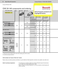
14 <strong>Bosch</strong> <strong>Rexroth</strong> <strong>Corp</strong>oration Compact Modules <strong>CKK</strong>/C<strong>KR</strong> 9-70 R310A 2624 (2009.05)Compact Module <strong>CKK</strong><strong>CKK</strong> 9-70Part number, lengthType Guideway Drive unit CarriageR0360 200 00, ... mmWithout motor mountScrewjournalBall screwsize d 0 x P8 x 2.5Short carriage (32 mm) Long carriage (73 mm)Connection plate Connection platewithout with without withOF01 01 Ø6 01 01 40 02 41With motor mountMF01 01 Ø6 01 01 40 02 41With timing belt side driveRV02RV01RV03RV01-RV0401 Ø6 01 01 40 02 41RV041) Attachment kit also available without motor (when ordering: enter “00” for motor)Order example: see “Inquiry / Order form” section.Please make sure that the selected combination is a permissible one (load capacities, moments, max. speeds, motor data, etc.)!Switch mounting arrangementsA mounting duct is needed to fasten the switches. Switches may be mounted onlyon one side of the Compact Module (left or right).Refer to “Switch mounting arrangements” for more information on switch types andswitch mounting.
R310A 2624 (2009.05) Compact Modules <strong>CKK</strong>/C<strong>KR</strong> 9-70<strong>Bosch</strong> <strong>Rexroth</strong> <strong>Corp</strong>oration15Motor attachment Motor Cover SwitchSocket, plugMounting ductDocumentationGearratioi =Attachmentkit 1) for motor Motor typewithout withbrake brakeGap-type sealsmade of PU stripwithout withStandardreportMeasurementreport0011.501MSK030C84 8502 VRDM 368 35 3603MSM030B70 7104MSM020B68 6911131214MSK030CMSM030BMSK030CMSM030B84 8570 7184 8570 7101 02Without switchWithout mounting ductMagnetic field sensorReed sensorHall sensor21 Mountingduct25PNP - NC 22 Length = LcontactMagnetic field sensor with plug 2)Reed sensor 58Hall sensorPNP - NCcontact5900SocketPlug170102Frictionaltorque03Leaddeviation05PositioningaccuracyCalculating the lengthof the Compact Module (example)L = (stroke + 2 · excess travel)+ L ca + 30 mmStroke = Maximum distance fromcarriage center to theoutermost switch activationpoints.Stroke = 200 mmL ca = 73 mmL = ((200+ 2 · 2.5) + 73 + 30) mmIn most cases, the recommended limitfor excess travel (braking distance) is:Excess travel = 2 · screw lead PExample:Ball screw 8 x 2.5 (d 0 x P),Excess travel = 2 · 2.5 = 5 mm
16 <strong>Bosch</strong> <strong>Rexroth</strong> <strong>Corp</strong>orationCompact Modules <strong>CKK</strong>/C<strong>KR</strong> 9-70 R310A 2624 (2009.05)Compact Module <strong>CKK</strong><strong>CKK</strong> 9-70 DimensionsAll dimensions in mmDrawings not to caleMax. travel / 2L ca 73 (long carriage)Max. travel / 2Ø6 h7Excesstravel16Effective stroke / 2L ca 32 (short carriage)Effective stroke / 2ExcesstravelD18 22L/229One-point lubrication on both sides(grease lubrication): Funnel-typeLlube nipple DIN 3405-D3Long carriageM3 - 5 deep (8x)40Ø3 H7 - 5 deep (8x)25 15 25Lube ports for grease lubrication;ports closed with set screw M3.73OF01RV01-RV04.MF01G L m40FLsdH E KD
R310A 2624 (2009.05) Compact Modules <strong>CKK</strong>/C<strong>KR</strong> 9-70<strong>Bosch</strong> <strong>Rexroth</strong> <strong>Corp</strong>oration173323For connection plate,see section on “Mounting”Ø282,5 deepM4 - 8 deep (4x)B31.33244.5Short carriage5Ø3 H7 - 5 deep (2x)4070(Frame dimension)AA45°B3.21.3404.5 2.52.8For fastening with clamping fi xtures4.83.2 1.8For mounting duct, socketM3 - 5 deep (4x)2532Lube ports for greaselubrication;ports closed with setscrew M3.Type Motor Dimensions (mm)D E F G H K L f L m L sdi=1 i=1.5 withoutbrakewithbrakeRV01/RV02 MSM 030B 60 78 75 64.5 37 16 33.5 – 111 144 157RV03/RV04 MSK 030C 54 – 188 213 154MF01 MSM 020B 42 – – – – – – 44 109 140 –MSM 030B 60 – – – – – – 50 111 144 –MSK 030C 54 – – – – – – 50 110 157 –VRDM 368 57.2 – – – – – – 50 188 213 –
18 <strong>Bosch</strong> <strong>Rexroth</strong> <strong>Corp</strong>oration Compact Modules <strong>CKK</strong>/C<strong>KR</strong> 9-70 R310A 2624 (2009.05)Compact Module C<strong>KR</strong>Product OverviewCompact Modules are precision, ready-to-install linear motion systems offering high performance,compact design, and good price/performance ratio with fast delivery time.Structural design– Extremely compact precision aluminumprofi le with two integrated ballrail systems for optimal travel performanceand movement of heavy loadsat high travel speeds– Ready-to-install Compact Modulesin selectable lengths up to L max– Short or long carriage made ofaluminum with integrated runnerblocks– Driven by a pre-tensioned toothedbeltAttachments– Maintenance-free digital servo driveswith integrated brake and attachedfeedback– Gear reducer– Reed or Hall sensors– Socket with mating plug for theswitches– Aluminum profi le mounting ductOther distinguishing features– Precise alignment and secure fastening of attachments with threads andpin holes and through short or long carriage– Idler (non-drive) end enclosure with integrated belt-tensioning system.Pulley ball bearings are lubricated for life– Economical maintenance thanks to one-point lubrication feature (greaselubrication) for ball rail systems at sides or through the carriage– Easy motor attachment by means of locating feature and fastening threadson drive end enclosure– Two integrated zero-clearance ball rail systems provide optimized travelperformance, high load capacities, and high rigidity– High travel speed with high precision and smooth operation over long lengths– Gap-type sealings and side-mounted aluminum rails for guiding the toothed belt– Adjustable switches over the entire travel range, switch activation withoutswitching cam
R310A 2624 (2009.05) Compact Modules <strong>CKK</strong>/C<strong>KR</strong> 9-70<strong>Bosch</strong> <strong>Rexroth</strong> <strong>Corp</strong>oration19Connection plate for easy installationGear reducer:A variety of gear ratios allow an optimal match between theload and the drive motor inertia.
20 <strong>Bosch</strong> <strong>Rexroth</strong> <strong>Corp</strong>orationCompact Modules <strong>CKK</strong>/C<strong>KR</strong> 9-70 R310A 2624 (2009.05)Compact Module C<strong>KR</strong>Structural designStructural design C<strong>KR</strong>1 Toothed belt2 Drive end enclosure3 Carriage versions––Short carriage with two runnerblocksLong carriage with four runnerblocks4 Frame5 Idler (non-drive) end enclosure1435Attachments:6 Magnetic fi eld sensor7 Mounting duct8 Socket/plug9 Motor10 Gear reducer11 Connection plate728611910
R310A 2624 (2009.05) Compact Modules <strong>CKK</strong>/C<strong>KR</strong> 9-70<strong>Bosch</strong> <strong>Rexroth</strong> <strong>Corp</strong>oration21Structural design of gearreducerFor all Compact Modules C<strong>KR</strong>, aplanetary gearbox can be installed via afl ange. The fl ange serves as a mountingpoint for the gearbox to the CompactModule. This direct connection eliminatesthe need for a coupling, therebyminimizing torsional defl ection.Several different gear ratios are available:i = 5i = 101 Motor2 Gear reducer3 Flange4 Drive end enclosure5 Compact Module43215
22 <strong>Bosch</strong> <strong>Rexroth</strong> <strong>Corp</strong>oration Compact Modules <strong>CKK</strong>/C<strong>KR</strong> 9-70 R310A 2624 (2009.05)Compact Module C<strong>KR</strong>Technical dataGeneral technical dataSize Carriage Belt type Dynamicload capacityof guidewayDynamicmomentsPlanar moment ofinertiayzyMoved mass m B (kg)Connection plateMaximumlengthSpecificspring rateC(N)M t(Nm)M L(Nm)I y(cm 4 )I z(cm 4 )without with L max(mm)c spec(N/mm · m)C<strong>KR</strong> 9-70 short AT 3 2360 47 7 8.5 55.1 0.12 0.23 1500 275long AT 3 3830 76 94 0.28 0.45zToothed belt stretch ΔL = (F · L)/c specE = 70,000 N/mm 2Maximum permissible loadsSize Carriage Maximum permissible forces (N) Maximum permissible moments (Nm)F z1 max F z2 max F y max M x max M y max , M z maxC<strong>KR</strong> 9-70 short 1180 1180 1590 23 7long 2360 2360 1180 47 28Modulus of elasticity ESize Carriage Drive type Weight Additional weight of gear reducer(mm)(kg)(kg)C<strong>KR</strong> 9-70 short Without drive 0.0028 · L + 0.585 –Drive i = 1 0.0028 · L + 0.575 0.435long Without drive 0.0028 · L + 0.74 –Drive i = 1 0.0028 · L + 0.73 0.435WeightWeight calculation without motor, switchesand sensors.Weight formula:Weight factor (kg/mm) · length L (mm) + weight of all parts of fi xed length (carriage,drive and idler end enclosures, etc.) (kg) + additional mass (kg)Note on dynamic load capacities andmomentsDetermination of the dynamic loadcapacities and moments is based on atravel life of 100,000 m.Often only 50,000 m are actuallystipulated.For comparison: Multiply values C, M tand M L from the table by 1.26.F z1 maxM t /M x maxF z2 maxF y maxLong carriage Short carriageF y maxM L /M y maxM L /M z maxM L /M z max
R310A 2624 (2009.05) Compact Modules <strong>CKK</strong>/C<strong>KR</strong> 9-70<strong>Bosch</strong> <strong>Rexroth</strong> <strong>Corp</strong>oration23Drive dataSize Drive type Gear reducerratioiMax. drivetorque 1)M a(Nm)Leadconstantu(mm/rev)BelttypeWidthb(mm)ToothpitchT(mm)Max. belt drivetransmission forceF(N)Belt elasticitylimitF perm(N)C<strong>KR</strong> 9-70 i = 1 1 3.0 72.0 AT 3 25 3 260 1100Gear reducer 5 0.6 14.410 0.3 7.21)Maximum 1,000 cycles/hourDrive data without motor (i = 1)SizeDrive unit diameter(mm)Lead constantu(mm/rev)Travel speedv mech(m/s)Belt typeC<strong>KR</strong> 9-70 22.92 72.0 up to 3 AT 3Width 25 mmReduced mass moment of inertia atmotor journalshort carriage(kgm 2 )long carriage(kgm 2 )3.01 · 10 -5 3.9 · 10 -5Frictional torque dataSize Motor Gear unit type i M RS(Nm)M RLP(Nm)C<strong>KR</strong> 9-70 MSM020BMSK030CGear reducer 5, 10 0.25 0.03For calculation and calculation example, see catalog Compact Modules R310A 2602
24 <strong>Bosch</strong> <strong>Rexroth</strong> <strong>Corp</strong>oration Compact Modules <strong>CKK</strong>/C<strong>KR</strong> 9-70 R310A 2624 (2009.05)Compact Modules C<strong>KR</strong>C<strong>KR</strong> 9-70 Components and OrderingPart number, lengthType Guideway Drive unit CarriageR0364 200 00, ... mmWithout driveOA01ShaftformotorWithoutkeywayi = 1without 50Gearreduceri = 5, 10Short (80 mm) Long (108 mm)Connection plate Connection platewithout with without withWith driveMA01 right 01MA02 left 020101 40 02 41MA05 right 06MA06 left 07With gear reducer MG 10MG10MG10 01withgearreducer,right08With gear reducer MG 1101 40 02 41MG11MG1101withgearreducer,left091) Attachment kit also available without motor (when ordering: enter “00” for motor)2) Including mounting accessoriesNote: For gear unit performance data, see “Performance data” section.C<strong>KR</strong> with second shaft endIn types MA05, MA06, MG10 and MG11 a second drive shaft end can be madeavailable by removing the screws and cover.
R310A 2624 (2009.05) Compact Modules <strong>CKK</strong>/C<strong>KR</strong> 9-70<strong>Bosch</strong> <strong>Rexroth</strong> <strong>Corp</strong>oration25Motor attachment 1) Motor SwitchSocket, plugMounting ductDocumentationDirectdrivei = 5 i = 10 withoutbrakewithbrakeStandardreportMeasurementreport00 00 00 00Without switchWithout mounting ductMagnetic field sensor0002FrictionaltorqueReed sensor 21 MountingductHall sensorPNP - NCcontact2225Length = LMagnetic field sensor with plug 2)SocketPlug170105Positioningaccuracy11 12 MSK 030C 84 85Reed sensor 58Hall sensorPNP - NCcontact5921 22 MSM 020B 68 69Length of the Compact ModuleL = (stroke + 2 · excess travel)+ L T + 10 mmStroke = Maximum distance fromcarriage center to the outermostswitch activation points.Stroke = 400 mmL T = 108 mmL = ((400+ 2 · 110) + 108 + 10) mmL = 738 mmThe excess travel must be greater thanthe braking distance.You can use acceleration travel s as arecommended value for the braking distance(see “Performance data” tables).Example C<strong>KR</strong> 9-70:Horizontal operation with motor MSK030C, i = 5, m = 2 kg, s = 105 mmExcess travel > 105 mm (110 mmassumed)A mounting duct is needed to fasten theswitches. Switches may be mountedonly on one side of the Compact Module(left or right).Refer to “Switch mounting arrangements”for more information on switchtypes and switch mounting.
26 <strong>Bosch</strong> <strong>Rexroth</strong> <strong>Corp</strong>orationCompact Modules <strong>CKK</strong>/C<strong>KR</strong> 9-70 R310A 2624 (2009.05)Compact Modules C<strong>KR</strong>C<strong>KR</strong> 9-70 DimensionsAll dimensions in mmDrawings not to cale Max. travel / 2Effective stroke / 2Max. travel / 2Effective stroke / 23629ExcesstravelL ca 108 (long carriage)L ca 80 (short carriage)Excesstravel42X3636427031.316.312M3 - 6 deep (8x)18Ø26.5 H73 deepØ3 H7 - 6 deep (4x)L/2LLong carriage12.5 12.5 15 12.5 12.5One-point lubrication on both sides(grease lubrication): Funnel-typelube nipple DIN 3405-D3M3 - 6 deep (8x)13.514.5Ø8 h7108Lube ports for grease lubrication;ports closed with set screw M4.OA01 MA01 / MA02 MA05 / MA06X15212Ø8 h7Ø26.5 H770702Ø 26.5H714.514.5H7Ø1012 deepØ8 h7
R310A 2624 (2009.05) Compact Modules <strong>CKK</strong>/C<strong>KR</strong> 9-70<strong>Bosch</strong> <strong>Rexroth</strong> <strong>Corp</strong>oration2721For connection plate,see section on “Mounting”BA2.845°4.5 2.5For fastening withclamping fi xtures70(Frame dimension)4.8B3.21.31.8L m3.2For mounting duct, socketL f 31.33244.5XAMG10 / MG11M3 - 6 deep (4x)13.5Short carriageLube ports for grease lubrication;ports closed with set screw M4.12.5 12.5M3 - 6 deep (2x)MotorDimensions (mm)D L f L mwithoutbrakewithbrakeMSM 020B 42 91.0 109 140.0MSK 030C 54 91.0 188 213.0D
28 <strong>Bosch</strong> <strong>Rexroth</strong> <strong>Corp</strong>oration Compact Modules <strong>CKK</strong>/C<strong>KR</strong> 9-70 R310A 2624 (2009.05)Compact ModulesPerformance dataC<strong>KR</strong> 9-70:– with long carriage– without connection plate– with gear reducerfor motors with brake in horizontal operationc The data below apply only to the combination described here.For other combinations the performance data must be recalculated.Servomotor MSK 030C and IndraDrive controller 1)Connection voltage: 3 x 400 VGear reducer ratio i = 5 i = 10Mass (kg) 2 4 6 8 10 2 4 6 8 10Acceleration time t (ms) 109 131 152 174 196 210 221 233 245 256Acceleration distance s (mm) 105 126 146 167 188 101 106 112 118 123Acceleration a (m/s 2 ) 17.6 14.7 12.6 11.8 9.8 4.6 4.3 4.1 3.9 3.7Speed v (m/s) 1.92 0.96Repeatability (mm) 0.1 0.1Servomotor MSM 020B and Regler ECODRIVE Cs controller 1)Connection voltage: 1 x 230 VGear reducer ratio i = 5 i = 10Mass (kg) 0.5 1 1.5 2 2.5 1.5 2 2.5 3 3.5Acceleration time t (ms) 9 11 13 15 17 33 34 35 36 37Acceleration distance s (mm) 3 4 5 6 6 6 6 6 7 7Acceleration a (m/s 2 ) 78.1 64.1 54.3 47.1 41.6 10.9 10.5 10.2 9.9 9.6Speed v (m/s) 0.72 0.36Repeatability (mm) 0.1 0.11)For additional information, refer to the “ECODRIVE Cs” and “IndraDrive for Linear Motion Systems” catalogs.
R310A 2624 (2009.05) Compact Modules <strong>CKK</strong>/C<strong>KR</strong> 9-70<strong>Bosch</strong> <strong>Rexroth</strong> <strong>Corp</strong>oration29Notes
30 <strong>Bosch</strong> <strong>Rexroth</strong> <strong>Corp</strong>orationCompact Modules <strong>CKK</strong>/C<strong>KR</strong> 9-70 R310A 2624 (2009.05)Switch mounting arrangementsOverview of switching systemsMagnetic field sensorMagnetic field sensor with plugThe following switch categories can be used with the Compact Module:– Magnetic fi eld sensor (Hall and Reed sensors)The entire switching system must be mounted on one side of the Compact Module!Magnetic field sensorHall and Reed sensor1 Socket and plug2 Switch3 Mounting duct(aluminum alloy, black anodized)2cThe magnetic field sensors aresuitable for travel speeds up to 2 m/s.Short stroke: Take the length of theswitch and socket into consideration!13356Set screw forfi xing in place6.5 35Active surfaceMagnetic fi eld sensors with potted cable.Version:– Hall sensor (normally closed) or– Reed sensor (change-over)Mounting instructions:Switches may be mounted only on one side of the Compact Module (left or right) and only after installing the Compact Module tothe mounting base. A mounting duct is needed to fasten the switches.Hall sensorContact typePNP - NC / NOReed sensorContact typeChange-overOperating voltage3.8–30 V DCSwitching voltagemax. 100 V DCPower consumptionmax. 10 mASwitching currentmax. 0.5 mAOutput currentmax. 20 mACable length2 m (10 m upon request)Cable length2 m (10 m upon request)Housing protection class IP 66Housing protection class IP 66Maximum travel speed2 m/sShort-circuit protectionNoMaximum travel speed 2 m/s Important: 2 switching points!Pin assignmentHall sensorWhite:+3.8...30 VDCGreen: OutputReed sensorBrownWhiteBrown:0 V groundGreen
R310A 2624 (2009.05) Compact Modules <strong>CKK</strong>/C<strong>KR</strong> 9-70<strong>Bosch</strong> <strong>Rexroth</strong> <strong>Corp</strong>oration31Mounting ductFunction:– To attach and secure magnetic fi eldsensors– Cable routing3.512Mounting instructions:The mounting duct is hooked into theT-slots of the module frame and securedwith set screws.Set screws are included.1419The switches are slid into the T-slot ofthe mounting duct and secured withset screws.Socket and plugAttach the socket on the side with themagnetic fi eld sensor.3 50 4.54927.5The socket and plug have 16 pins.Socket and plug are not wired.This allows optimal assignment of switchpositions during start-up.One plug is included.The plug can be installed in three directions.Ø2628.5PG 166016-pin plugPart numbers of the magnetic fieldsensors and accessoriesItemPart numbers1 Socket-plug R0375 400 002 Magnetic field sensor– Reed sensor R987 146 948– Hall sensor (PNP - NC) R987 146 1233 Mounting duct R0399 801 20
32 <strong>Bosch</strong> <strong>Rexroth</strong> <strong>Corp</strong>orationCompact Modules <strong>CKK</strong>/C<strong>KR</strong> 9-70 R310A 2624 (2009.05)Switch mounting arrangementsMagnetic fi eld sensor with plugWith magnetic fi eld sensors, switch activationis direct (without switching cam).The switch positions can be adjustedfreely over the entire travel range.Sensors may be mounted only on one sideof the Compact Module (left or right) andonly after installing theCompact Module to the mounting base.2144aSwitch positions:1 Limitation at end of stroke (recommendation:Reed or Hall sensor)2 Reference point in middle of stroke(recommendation: Hall sensor)Sensor mounting assemblyconsists of:3 Sensor (Hall or Reed)4 Sensor mount incl. set screws (loose)and square nut 4a5 Cable holder (3 units) incl. set screw(loose)1 5VersionPart numberSensor mounting assembly with Reed sensor R0375 300 07Sensor mounting assembly with Hall sensor R0375 300 083Sensor configuration:Set screw M3Activation pointSensor mountA sensor mount (1) is required to attachthe sensors. It is hooked into theupper slot on the Compact Module andsecured with set screws (2).The sensors are pushed into the upperslot of the sensor mount and fi xed with aset screw.The square nut with set screw (3) servesas a positive stop for the sensor (switchposition when changing sensors).Parts are included with the sensor mountingassembly.7.926.4
R310A 2624 (2009.05) Compact Modules <strong>CKK</strong>/C<strong>KR</strong> 9-70<strong>Bosch</strong> <strong>Rexroth</strong> <strong>Corp</strong>oration33Technical data and orderingHall sensorPart number R3476 024 03Dimension X13.65 mmContact typePNP - NCOperating voltage 3.8 to 30 V DCPower consumption max. 10 mAOutput currentmax. 20 mAHousing protection class IP 66Short-circuit protection NoPermissible travel speed 2 m/sHousing material UltramidReed sensorPart number R3476 023 03Dimension X9 mmContact typeChange-overSwitching voltage max. 100 V DCSwitching current max. 500 mAHousing protection class IP 66Permissible travel speed 2 m/sHousing material UltramidImportant: 2 switching pointsPin assignmentHall sensor1: +3.8 to30 VDC4: OutputReed sensor143: 0 V ground3–Hall sensor (PNP - NC contact)–Reed sensor (change-over)Extension cable for sensor(Reed/Hall)The extension cable (approx. 5 m) issupplied complete with a femaleconnector M8x1 for connection to thesensor.431~35Extension cablePart number Connector contact 1 3 4 Protection classR3476 025 03 to core brown blue black IP 66 when connectedM8x1
34 <strong>Bosch</strong> <strong>Rexroth</strong> <strong>Corp</strong>orationCompact Modules <strong>CKK</strong>/C<strong>KR</strong> 9-70 R310A 2624 (2009.05)MountingMounting, clamping fi xtures, centering ringCompact Modules are mounted usingclamping fi xtures.cDo not secure or support theCompact Module at the end enclosures!The frame is the load-bearing part!When mounting Compact Modules,please note the maximum tighteningtorques listed in the table.Mounting with clamping fixtures8295DRecommended number of clampingfi xtures:– 3 pieces per 500 mm and sideCEFCountersink for threadM 5 (ISO 4762)GFrame size 70 mmPart numberDimensions (mm)Clamping fixturesC D E F GR1419 010 01 15.0 6.5 4.8 10.0 22Tightening torques of fasteningscrews– with friction factor 0.125– strength class 8.88.8(Nm)max.M55.5Centering ringThe centering ring serves as a positioningaid and for positive locking whenmounting customer attachments to thecarriage.It creates a positive-locking connectionwith good reproducibility.Material: steel (stainless)DØFØCØAØBDØFØCØAH 1InstallationØA H7abcØB H7ØA H7H 1H 2EØ SizeDimensions (mm)Part numbera) Customer attachmentb) Centering ringc) CarriageA B C D E ØF H 1 H 2(mm) k6 k6 ±0.1 –0.2 +0.2 +0.2 +0.25 5 – 3.4 3.0 – 1.6 1.6 – R0396 605 427 7 – 5.5 3.0 – 1.6 1.6 – R0396 605 439 9 – 6.6 4.0 – 2.0 2.1 – R0396 605 4412 12 – 9.0 4.0 – 2.0 2.1 – R0396 605 4516 16 – 11.0 6.0 – 3.0 3.1 – R0396 605 467 - 5 7 5 3.4 3.0 1.5 1.6 1.6 1.6 R0396 605 479 - 5 9 5 3.4 3.5 1.5 1.6 2.1 1.6 R0396 605 489 - 7 9 7 5.5 3.5 1.5 1.6 2.1 1.6 R0396 605 4912 - 9 12 9 6.6 4.0 2.0 2.0 2.1 2.1 R0396 605 5016 - 12 16 12 9.0 5.0 2.0 2.0 3.1 2.1 R0396 605 51
R310A 2624 (2009.05) Compact Modules <strong>CKK</strong>/C<strong>KR</strong> 9-70<strong>Bosch</strong> <strong>Rexroth</strong> <strong>Corp</strong>oration35Connecting shafts for Compact Modules C<strong>KR</strong>Connecting shafts– Compensate for misalignments– Are backlash-free and torsionally stiff– Bridge large distances between axes– Can be mounted radially using splitclamping hubs (installation and removalwithout shifting pre-aligned axes)– Dynamically balancedMaterialBellows: highly fl exible stainless steelConnecting tube and clamping hub:aluminumScrew MOrdering dataPlease state the part number andlength L W .For example:R0391 510 22, L W = 550 mmSize Part number Dimensions (mm) M A M S M cs Mass moment ofWeight(Nm)inertiaA D M L Wmin L Wmax L W (Nm) (Nm) (10 –6 kgm 2 ) (kg)C<strong>KR</strong> 9-70 R0391 510 22 32 8 M4 95 1500 L M – 73 4 25 12.5 0.214 • L W (mm) + 7.91 0.000302 • L W (mm) + 0.118L M = centerline-to-centerline distance between Compact ModulesM A = tightening torque of screwsM cs = rated torque of connecting shaftM S = peak torque of connecting shaftTorsional stiffness c TMaximum rotary speed n(10 3 Nm/rad)1.00.50.0300 500 10001500L cs (mm)(min –1 )5000450040003500300025002000150010005000300 50010001500L cs(mm)Recommended rotary speed: 80% of maximum rotary speed
36 <strong>Bosch</strong> <strong>Rexroth</strong> <strong>Corp</strong>orationCompact Modules <strong>CKK</strong>/C<strong>KR</strong> 9-70 R310A 2624 (2009.05)MountingConnection plates for <strong>CKK</strong>/C<strong>KR</strong> 9-70Connection plate for <strong>CKK</strong>Function:– Fastening of attachments (with slidingblocks)– Lubrication possible from two sides(designed for one-point lubricationthrough only one of the two sides)Assembly consists of:– Connection plate– Mounting accessories for fasteningto the carriagesSliding blocks are not included withdelivery.Short carriageAb)10 10 10 1070a)20 204 +0.3 2 +0.2Detail AFrame size 705.7 ±0.24.2 +0.21x45°Long carriageB12.510 1032.5 32.56020 20 10 104.5Detail B70a)20 2084.3952.24b)a) Funnel-type lube nipple DIN 3405-D4b) Ø 7 H7 , 1.6 +0.2 deepFrame sizePart number for assemblyShort carriage Long carriage70 R0375 200 15 R0375 200 10
R310A 2624 (2009.05) Compact Modules <strong>CKK</strong>/C<strong>KR</strong> 9-70<strong>Bosch</strong> <strong>Rexroth</strong> <strong>Corp</strong>oration37Connection plate for C<strong>KR</strong>Function:– Fastening of attachments (with slidingblocks)– Lubrication possible from two sides(designed for one-point lubricationthrough only one of the two sides)Assembly consists of:– Connection plate– Mounting accessories for fasteningto the carriagesSliding blocks are not included withdelivery.Short carriageAb)10 10 10 1070a)20 20Detail AFrame size 705.7 ±0.2B12.532.56032.54.2 +0.2Long carriage4 +0.3 2 +0.21x45°10 1020 20 10 104.5Detail B70a)20 2084.3952.24b)a) Funnel-type lube nipple DIN 3405-D4b) Ø 7 H7 , 1.6 +0.2 deepFrame sizePart number for assemblyShort carriage Long carriage70 R0375 200 16 R0375 200 11
38 <strong>Bosch</strong> <strong>Rexroth</strong> <strong>Corp</strong>orationCompact Modules <strong>CKK</strong>/C<strong>KR</strong> 9-70 R310A 2624 (2009.05)MountingConnection of Compact Modules via cross-plateY-axis connected by the frame(carriage travels)Y-axis connected by thecarriage (frame travels)Y-axisY-axisX-axisX-axisVersions:X-axisSelect carriages and long connection plate according to table“Components and ordering” (option number 41).Y-axisThe number of carriages and the connection plate can be freelyselected according to table “Components and ordering”.Versions:Select X-axis and Y-axis with longconnection plate according to table “Components andordering” (option number 41).Connection kit consisting of:– Clamping fi xtures– Sliding blocks– Screws– Centering ringsX-axis (Compact Modulewith connection plate– option no. 41)AY-axis(any carriage version)Frame size7070 R0391 202 38A (mm) 76.5Weight (kg) 0.1890 R0391 200 39A (mm) 88.0Weight (kg) 0.20
R310A 2624 (2009.05) Compact Modules <strong>CKK</strong>/C<strong>KR</strong> 9-70<strong>Bosch</strong> <strong>Rexroth</strong> <strong>Corp</strong>oration39MaintenanceLubricationLube nipple in frameOn each side of the frame of the Compact Modules there are holes through which the lube nipples in the carriage can beaccessed. Lubrication from one side only is suffi cient. The lube nipples are not always located centrally in the carriage.Move the carriage as specifi ed in the table.Carriage x (mm) Lube nipples<strong>CKK</strong> C<strong>KR</strong>short 12.5 0long 0 0DIN 3405-D3Schematic representationLube ports for carriage attachmentsThe lube ports are sealed with a set screw in the factory before shipment.To use, install according to the specifi ed connection dimensions and use O-rings to seal the interface.aØEØDF= =bcMda) Customer-built attachmentb) Carriagec) O-ringd) FrameCompact Carriage Dimensions (mm) O-ring for DIN3771ModuleA B ØD ØE F M Part number+0.2 +0.2 -0.1C<strong>KR</strong> - 0 0 2.5 5.0 0.6 M 3 3 x 1.0 R3411 001 01<strong>CKK</strong> short 40 5<strong>CKK</strong> long 40 0Lube nipples in connection plates for <strong>CKK</strong>/C<strong>KR</strong>Each connection plate has two funnel type lube nipples (1) according to DIN 3405-D4 located on its endfaces. Lubrication through only one of the two lube nipples is suffi cient.1Short stroke for <strong>CKK</strong>/C<strong>KR</strong>For short-stroke applications (stroke < 40 mm), please consult with usabout lubrication.
40 <strong>Bosch</strong> <strong>Rexroth</strong> <strong>Corp</strong>orationCompact Modules <strong>CKK</strong>/C<strong>KR</strong> 9-70 R310A 2624 (2009.05)MotorsServo motorsAC servo motors MSKMotor data/DimensionsDescription Symbol Unit MSK030C-0900Maximum usable speed n max (min –1 ) 9000Maximum torque M max (Nm) 4Rated torque M N (Nm) 0.8Rotor mass moment of J rot (10 –6 kgm 2 ) 30inertiaMass without brake m (kg) 2.1Holding brakeHolding torque M Br (Nm) 1.0Brake mass moment of J Br (10 –6 kgm 2 ) 7inertiaMass of brake m Br (kg) 0.25ØEØDB 1B 2B 3LL 1H 3H245°AR6032AØGØFH1MotorDimensions (mm)A B 1 B 2 B 3 ØD ØE ØF ØG H 1 H 2 H 3 L without L with L 1 Rk6 j6brake brakeMSK 030C 54 20 2.5 7.0 9 40 63 4.5 71.5 57.4 42.0 188 213.0 – R5AC-Servo motorsMotor data/DimensionsMotorDimensions (mm)A B 1 B 2 B 3 ØD ØE ØF ØG H 1 H 2 H 3 L without L withh6 h7brake brakeMSM 020B 42 24 2 7 8 22 48 3.4 55 27 39.8 109 140MSM 030B 60 30 3 7 11 50 70 4.5 73 27 34.0 111 144Description Symbol Unit MSM 020B MSM 030BMaximum usable speed n max (min –1 ) 3000 3000Maximum torque M max (Nm) 0.95 3.8Rated torque M N (Nm) 0.32 1.2Rotor mass moment of inertia J rot (10 –6 kgm 2 ) 3.20 17Mass without brake m (kg) 0.50 1.5Holding brakeHolding torque M Br (Nm) 0.29 1.27Brake mass moment of inertia J Br (10 –6 kgm 2 ) 0.40 3Mass of brake m Br (kg) 0.20 0.4NotesAll servo motors have an absolute multiturn encoder.The motors can be supplied complete with control system.For additional information, refer to the “ECODRIVE Cs” and “IndraDrive for Linear Motion Systems” catalogs.
R310A 2624 (2009.05) Compact Modules <strong>CKK</strong>/C<strong>KR</strong> 9-70<strong>Bosch</strong> <strong>Rexroth</strong> <strong>Corp</strong>oration41Three-phase stepping motors3hree-phase stepping motorsVRDMNotesAll VRDM motors are equipped with anencoder for rotation monitoring.Key to illustration1 Motor connector2 Brake3 Encoder connector4 Brake connectorVRDM 368Ø EØ DB 1 L ± 0. 5 41B 2B 331345114Ø15Ø514321A182121Ø FØ G313125DimensionsMotorDimensions (mm)A B 1 B 2 B 3 ØD ØE ØF ØG L LwithoutbrakewithbrakeVRDM 368 57.2 21 1.6 5 8 –0.013 38.1±0.02566.7 5.2 116.0 157.0Motor dataMotor Unit VRDM 368Maximum permissible torque M max (Nm) 1.50Motor mass moment of inertia J m (10 –6 kgm 2 ) 38Motor holding torque M m (Nm) 1.74Mass without brake m m (kg) 1.1Step count z (–) 200 / 400 / 500 / 1000 /2000 / 4000 / 5000 / 10000Stepping angle per step (°) 1.8 / 0.9 / 0.72 / 0.36 / 0.18 /0.09 / 0.072 / 0.036Encoder resolution1000 increments/revolutionHolding brakeBrake holding torque M br (Nm) 1Brake mass moment of inertia J br (10 –6 kgm 2) 1.6Mass of brake m br (kg) 0.5NotesThe motors can be supplied complete with control system.
42 <strong>Bosch</strong> <strong>Rexroth</strong> <strong>Corp</strong>orationCompact Modules <strong>CKK</strong>/C<strong>KR</strong> 9-70 R310A 2624 (2009.05)DocumentationStandard reportOption no. 01The standard report serves to confi rm that the checks listed in the report havebeen carried out and that the measured values lie within the permissible tolerances.Frictional torque of completesystemOption no. 02The moment of friction is measured overthe entire travel range.M (Nm)3.22.41.60.800.81.62.43.2AdvanceReturnt (ms)M (Nm)Lead deviation of ball screwdrive for Compact Module <strong>CKK</strong>Option no. 03A measurement report in table form isprovided in addition to the graph (seeillustration).Positioning accuracyto VDI/DGQ 3441Option no. 05Deviation (μm)Example300240180120600-60-120-180-240-3000200 400 600 800 1000 1200 1400 1600 1800 2000Measured travel (mm)Measurement points are selected atirregular intervals along the travel range.This allows even periodical deviations tobe detected during positioning.Each measurement point is approachedseveral times from both sides.This gives the following parameters:Deviation (mm). . . .Set position (mm)Positioning accuracy PThe positioning accuracy corresponds to the total deviation. It encompasses all the systematic and random deviationsduring positioning. The positioning accuracy takes the following characteristic values into consideration:position deviation, reversal range, position variation rangePosition deviation P aThe position deviation corresponds to the maximum difference arising in the mean values of all the measurementpoints. It describes systematic deviations.Reversal range UThe reversal range corresponds to the difference in mean values of the two approach directions. The reversal range isdetermined at every measurement point. It describes systematic deviations.Position variation range P SThe position variation range describes the effects of random deviations. It is determined at every measurement point.
R310A 2624 (2009.05) Compact Modules <strong>CKK</strong>/C<strong>KR</strong> 9-70<strong>Bosch</strong> <strong>Rexroth</strong> <strong>Corp</strong>oration43Inquiry / Order form<strong>Bosch</strong> <strong>Rexroth</strong> <strong>Corp</strong>oration14001 South Lakes DriveCharlotte, NC 28273<strong>Rexroth</strong> Compact ModulesPhone: (704) 583-4338 / 800-438- 5983Fax: (704)583-0523www.boschrexroth-us.comOrder exampleOrder dataExplanationCompact Module (part number): R0364 200 00, 738 mm Compact Module C<strong>KR</strong> 9-70, length = 738 mmType = MG10 With gear reducer according to illustration MG10Guideway = 01 Ball Rail SystemDrive unit = 08 Drive end enclosure for attaching gear reducer at rightCarriage = 02 Carriage with length L T = 108 mmMotor attachment = 11 for motor MSK 030C, i = 5Motor = 85 Motor MSK 030C with brake1st switch = 21 Reed sensor2nd switch = 22 Hall sensor, PNP - NC3rd switch = 21 Reed sensorMounting duct / cable duct = 25 Mounting duct, delivered as separate partSocket-plug = 17 Socket-plug, delivered as separate partDocumentation = 02 Measurement report: Frictional torqueTo be completed by customer: Inquiry / OrderCompact Module ________________________________(Part number): R_____ ______ ______, Length _________mmType =Guideway =Drive unit =Carriage =Cover (for <strong>CKK</strong>) =Motor attachment =Motor =1st switch =2nd switch =3rd switch =Mounting duct / cable duct = , mmSocket-plug =Documentation =Individual parts:(Part number):R______ _______ _______R______ _______ _______R______ _______ _______R______ _______ _______QuantityComments:Order of: _____ pcs, ______ per month, _______ per year, per order, or __________________________SenderCompany:Address:Name:Department:Telephone:Fax:
<strong>Bosch</strong> <strong>Rexroth</strong> <strong>Corp</strong>orationLinear Motion andAssembly Technologies14001 South Lakes DriveCharlotte, NC 28273Telephone (800) 438-5983Facsimile (704) 583-0523www.boschrexroth-us.com<strong>Bosch</strong> <strong>Rexroth</strong> <strong>Corp</strong>oration<strong>Corp</strong>orate Headquarters5150 Prairie Stone ParkwayHoffman Estates, IL 60192-3707Telephone (847) 645-3600Facsimile (847) 645-6201<strong>Bosch</strong> <strong>Rexroth</strong> <strong>Corp</strong>orationIndustrial Hydraulics2315 City Line RoadBethlehem, PA 18017-2131Telephone (610) 694-8300Facsimile (610) 694-8467<strong>Bosch</strong> <strong>Rexroth</strong> <strong>Corp</strong>orationElectric Drives and Controls5150 Prairie Stone ParkwayHoffman Estates, IL 60192-3707Telephone (847) 645-3600Facsimile (847) 645-6201<strong>Bosch</strong> <strong>Rexroth</strong> <strong>Corp</strong>orationPneumatics1953 Mercer RoadLexington, KY 40511-1021Telephone (859) 254-8031Facsimile (859) 281-3491<strong>Bosch</strong> <strong>Rexroth</strong> <strong>Corp</strong>orationMobile Hydraulics1700 Old Mansfield RoadWooster, OH 44691-0394Telephone (330) 263-3300Facsimile (330) 263-3333Printed in the United StatesR310A 2624