

Throttle Body (3S–GTE) - CelicaTech
Throttle Body (3S–GTE) - CelicaTech
Throttle Body (3S–GTE) - CelicaTech

Create successful ePaper yourself
Turn your PDF publications into a flip-book with our unique Google optimized e-Paper software.
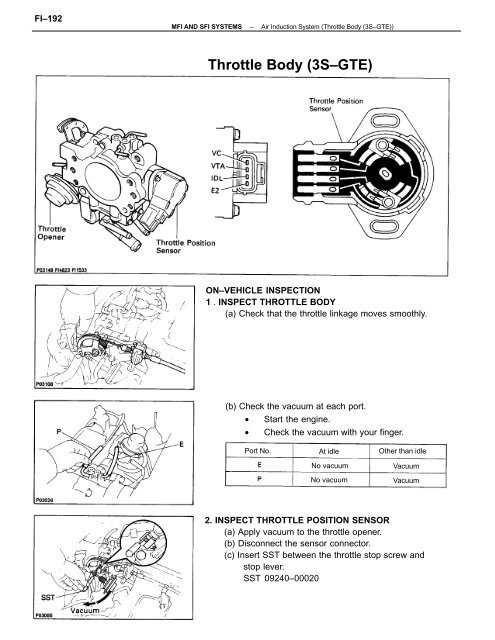
FI–192MFI AND SFI SYSTEMS–Air Induction System (<strong>Throttle</strong> <strong>Body</strong> (<strong>3S–GTE</strong>))<strong>Throttle</strong> <strong>Body</strong> (<strong>3S–GTE</strong>)ON–VEHICLE INSPECTION1 . INSPECT THROTTLE BODY(a) Check that the throttle linkage moves smoothly.(b) Check the vacuum at each port.• Start the engine.• Check the vacuum with your finger.Port No.At idleNo vacuumNo vacuumOther than idleVacuumVacuum2. INSPECT THROTTLE POSITION SENSOR(a) Apply vacuum to the throttle opener.(b) Disconnect the sensor connector.(c) Insert SST between the throttle stop screw andstop lever.SST 09240–00020
MFI AND SFI SYSTEMS–Air Induction System (<strong>Throttle</strong> <strong>Body</strong> (<strong>3S–GTE</strong>))FI–193(d) Using an ohmmeter, measure the resistance be–tween each terminal.Clearance betweenlever and stop screwBetween terminalsResistance0 mm (0 in.) VTA – E20.47 – 6.1 k0.50 mm (0.020 in.)0.70 mm (0.028 in.)<strong>Throttle</strong> valve fullyopenIDL – E2IDL – E2VTA – E22.3 k or lessInfinity3.1 – 12.1 kVC – E23.9 – 9.0 k(e) Reconnect the sensor connector.3. INSPECT THROTTLE OPENERA. Warm up engineAllow the engine to warm up to normal operating tem–perature.B. Check idle speedIdle speed: 800 ± 50 rpmC. Check throttle opener setting speed(a) Disconnect the vacuum hose from the throttleopener, and plug the hose end.(b) Check the throttle opener setting speed.<strong>Throttle</strong> opener setting speed:900 – 1,900 rpmIf the throttle opener setting is not as specified, replacethe throttle body.(c) Stop the engine.
FI–194MFI AND SFI SYSTEMS–Air Induction System (<strong>Throttle</strong> <strong>Body</strong> (<strong>3S–GTE</strong>))(d) Reconnect the vacuum hose to the throttle opener.(e) Start the engine and check that the idle rpm re–turns to the correct speed.REMOVAL OF THROTTLE BODY1. DISCONNECT CABLE FROM NEGATIVE TERMINALOF BATTERYCAUTION: Work must be started after approx. 20seconds or longer from the time the ignition switch isturned to the ”LOCK” position and the negative (–) ter–minal cable is disconnected from the battery.2. DRAIN ENGINE COOLANT (See page CO–6)3. DISCONNECT ACCELERATOR CABLE FROMTHROTTLE LINKAGE4. REMOVE CHARGE AIR COOLER(See steps 13 to 15 on pages TC–9 and 10)5. REMOVE INTAKE AIR CONNECTORRemove the four bolts and air connector.6. REMOVE INTAKE AIR CONNECTOR STAYRemove the two bolts, two nuts and air– connector stay.7. DISCONNECT THROTTLE POSITION SENSORCONNECTOR8. DISCONNECT IAC VALVE CONNECTOR
MFI AND SFI SYSTEMS–Air Induction System (<strong>Throttle</strong> <strong>Body</strong> (<strong>3S–GTE</strong>))FI–1959. REMOVE ACCELERATOR BRACKET10. DISCONNECT HOSES FROM THROTTLE BODY(a) PCV hose from cylinder head cover(b) Vacuum hose (from throttle body P port) fromvacuum pipe(c) Vacuum hose (from throttle body E port) from EGRVSV(d) Vacuum hose from throttle opener11. REMOVE THROTTLE BODY(a) Remove the four bolts, throttle body and gasket.(b) Disconnect the hoses from the throttle body, andremove the throttle body.(1) Two water by–pass hoses from No.1 air tube(2) Air hose from No.1 air tube12. IF NECESSARY, REMOVE IAC VALVE FROM THROTTLEBODYRemove the four screws, IAC valve and gasket.
FI–196MFI AND SFI SYSTEMS–Air Induction System (<strong>Throttle</strong> <strong>Body</strong> (<strong>3S–GTE</strong>))INSPECTION OF THROTTLE BODY1. CLEAN THROTTLE BODY(a) Using a soft brush and carburetor cleaner, clean thecast parts.(b) Using compressed air, clean all the passages andapertures.NOTICE: To prevent deterioration, do not clean thethrottle position sensor.2. INSPECT THROTTLE VALVE(a) Apply vacuum to the throttle opener.(b) Check that there is no clearance between thethrottle stop screw and throttle lever when thethrottle valve is fully closed.3. INSPECT THROTTLE POSITION SENSOR(See step 2 on page FI–192)4. IF NECESSARY, ADJUST THROTTLE POSITIONSENSOR(a) Loosen the two set screws of the sensor.(b) Apply vacuum to the throttle opener.(e) Insert a 0.60 mm (0.024 in.) thickness gauge, be–tween the throttle stop screw and stop lever.(d) Connect the test probe of an ohmmeter to the termi–nals IDL and E2 of the sensor.(e) Gradually turn the sensor clockwise until the ohm–meter deflects, and secure it with the two setscrews.(f) Recheck the continuity between terminals IDL andE2.Clearance betweenlever and stop screw0.50 mm (0.020 in.)0.70 mm (0.028 in.)Continuity (IDL – E2)ContinuityNo continuity
MFI AND SFI SYSTEMS–Air Induction System (<strong>Throttle</strong> <strong>Body</strong> (<strong>3S–GTE</strong>))FI–197INSTALLATION OF THROTTLE BODY1. INSTALL IAC VALVE TO THROTTLE BODY(a) Place a new gasket on the throttle body.(b) Install the IAC valve with the four screws.2. INSTALL THROTTLE BODY(a) Connect the following hoses to the throttle body:(1) Two water by–pass hoses to No.1 air tube(2) Air hose to No.1 air tube(b) Place a new gasket on the throttle body, facing theprotrusion upward.P029(c) Install the throttle body with the four bolts.Torque: 19 N–m (195 kgf–cm, 14 ft–lbf)HINT: Each bolt is indicated in the illustration.Bolt length: A 45 mm (1.77 in.)B 70 mm (2.76 in.)
FI–198MFI AND SFI SYSTEMS–Air Induction System (<strong>Throttle</strong> <strong>Body</strong> (<strong>3S–GTE</strong>))3. CONNECT HOSES TO THROTTLE BODY(a) PCV hose to cylinder head cover(b) Vacuum hose (from throttle body P port) to vacuumpipe(c) Vacuum hose (from throttle body E port) to EGRVSV(d) Vacuum hose from throttle opener4. INSTALL ACCELERATOR BRACKET5. CONNECT lAC VALVE CONNECTOR6. CONNECT THROTTLE POSITION SENSORCONNECTOR7. INSTALL INTAKE AIR CONNECTOR STAYInstall the air connector stay with the two bolts and twon uts.Torque:Bolt 19 N–m t195 kgf–cm, 14 ft–Ibf)Nut 7.8 N–m (80 kgf–cm, 69 in.–Ibf)8. INSTALL INTAKE AIR CONNECTORInstall the air connector with the four bolts.Torque: 19 N–m (195 kgf–cm, 14 ft–lbf)9. INSTALL CHARGE AIR COOLER(See steps 11 to 13 on page TC–17)10. CONNECT ACCELERATOR CABLE, AND ADJUST IT11. FILL WITH ENGINE COOLANT (See page CO–6)12. CONNECT CABLE TO NEGATIVE TERMINAL OFBATTERY


