FTR1 Series Troffer Retrofit Kit Installation Instructions
FTR1 Series Troffer Retrofit Kit Installation Instructions
FTR1 Series Troffer Retrofit Kit Installation Instructions

Create successful ePaper yourself
Turn your PDF publications into a flip-book with our unique Google optimized e-Paper software.
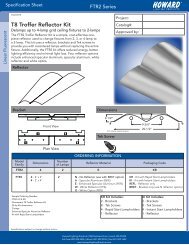
WARNINGS:-Risk of fire or electric shock. Reflector kit installation requires knowledge of fluorescent lighting luminaire electricalsystems. If not qualified, do not attempt installation. Contact a qualified electrician.-Reflector kit is not intended to be used in wet or damp locations.-Reflector kit is intended for use only with Surface Mounted or Type Non-IC Recessed Luminaires.-Risk of fire or electric shock. Install this kit only in a grounded luminaire that is UL Listed and has the constructionfeatures and dimensions shown in the photographs and/or drawings.-To prevent wiring damage or abrasion, do not expose wiring to edges of sheet metal or other sharp objects.-Risk of fire or electric shock. Luminaires wiring, ballasts, or other electrical parts may be damaged when drilling forinstallation of reflector kit hardware. Check for enclosed wiring and components.-Do not make or alter any open holes in an enclosure of wiring or electrical components during kit installation.-Not suitable for use on aluminum luminaires.<strong>Installation</strong> <strong>Instructions</strong>:1) Turn off power to fixture. Remove lens/door, lamps, ballasts, lampholders, and socket barsfrom the existing fixture.2) Install the end caps into the ends of the fixture byinserting the bottom flange between the bottom of thefixture and the T-bar. The end cap with tethers goesnearest the power supply wires. Center the end capand attach it using the provided tek screws throughthe two holes at the top of the bracket. The use of anelectric screwdriver with magnetic socket isrecommended. Repeat on the opposite end.3) Ensuring the lamp side of the reflector kit faces away fromtroffer interior, suspend the body by threading tethersthrough long oblong holes (start with side that has tab).4) Insert the supply leads (black & white) throughthe access hole. Do not connect wires to theLuminaire Disconnect plug. Do not disconnect theground wire on the existing fixture.5) Swing the body into the housing. Be careful not toscratch end caps. Attach the body (by sliding the clearanceslots carefully over the screws on the end caps) first to theend opposite the tethers and fasten using self- tappingscrews. Fasten tether end next.1025-000000-052 r03