Basic Principles of Homing Guidance - The Johns Hopkins ...
Basic Principles of Homing Guidance - The Johns Hopkins ...
Basic Principles of Homing Guidance - The Johns Hopkins ...

You also want an ePaper? Increase the reach of your titles
YUMPU automatically turns print PDFs into web optimized ePapers that Google loves.
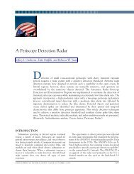
BASIC PRINCIPLES OF HOMING GUIDANCElevel <strong>of</strong> (sensor) measurement uncertainties, errors inthe assumptions used to model the engagement (e.g.,unanticipated target maneuver), and errors in modelingmissile capability (e.g., deviation <strong>of</strong> actual missile speed<strong>of</strong> response to guidance commands from the designassumptions). Nevertheless, the selection <strong>of</strong> a guidancestrategy and its subsequent mechanization are crucialdesign factors that can have substantial impact onguided missile performance. Key drivers to guidance lawdesign include the type <strong>of</strong> targeting sensor to be used(passive IR, active or semi-active RF, etc.), accuracy <strong>of</strong>the targeting and inertial measurement unit (IMU) sensors,missile maneuverability, and, finally yet important,the types <strong>of</strong> targets to be engaged and their associatedmaneuverability levels. We will begin by developing abasic model <strong>of</strong> the engagement kinematics. This willlay the foundation upon which PN, one <strong>of</strong> the oldestand most common homing missile guidance strategies,is introduced.Engagement Kinematics: <strong>The</strong> Line-<strong>of</strong>-SightCoordinate System<strong>The</strong> development presented here follows the onegiven in Ref. 1. In the sequel, the following notation isused: X = n 3 m (read n-by-m) matrix <strong>of</strong> scalar elementsx i,j, i = 1 … n, j = 1 … m; _ x = n 31 vector <strong>of</strong> scalar elementsx i , i = 1 … n; _ n 2x = / i = 1x i = Euclidean vectornorm <strong>of</strong> _ x; _ 1 x= _ x/ _ x = n 31 unit vector (e.g., _ 1 x = 1)in the direction <strong>of</strong> _ x; /t = time derivative with respectto a fixed (inertial) coordinate system; and d/dt = timederivative with respect to a rotating coordinate system.Consider the engagement geometry shown in Fig. 2,where _ r Mand _ r Tare the position vectors <strong>of</strong> the missileinterceptor and target with respect to a fixed coordinateframe <strong>of</strong> reference (represented by the triad { _ 1 x, _ 1 y, _ 1 z}).Consequently, we define the relative position vector <strong>of</strong>the target with respect to the missile as shown in Eq. 2:_ r =_rT – _ r M. (2)<strong>The</strong> relative position vector can be written as _ r = R _ 1 r,where R = _ r is the target–missile range, and _ 1 ris theunit vector directed along _ r (we refer to _ 1 ras the LOSunit vector). Differentiating the relative position vector,_ r = R_1r , with respect to the fixed coordinate system, weobtain the following expression for relative velocity _ v:v /r = Ro 1 R 1 . t r + t r(3)From Eq. 3, one can see that the rate <strong>of</strong> change <strong>of</strong> therelative position vector (i.e., relative velocity) comprisestwo components: (i) a change in _ r as a result <strong>of</strong> a changein length (Ṙ) and (ii) a change in direction (a rotation)as a result <strong>of</strong> the rate <strong>of</strong> change <strong>of</strong> the LOS unit vector.r1 tn =r tLOS coordinate 1 = r frame rrMissile r LOS1 = 1 r 1 n rMFixed coordinateframe1 x–1 zrT1 yTargetFigure 2. In the LOS coordinate frame, the LOS rate is perpendicularto the LOS direction and rotation <strong>of</strong> the LOS takes placeabout the – 1 .We define this change in direction by the vector _ n asgiven in Eq. 4:n / . t 1 rConsequently, a second unit vector, _ 1 n, is defined tobe in the direction <strong>of</strong> _ n as shown:1n(4)1r/t= =n.(5)1/ tnrFinally, to complete the definition <strong>of</strong> the (righthanded)LOS coordinate system, a third unit vector, _ 1 ,is defined as the cross product <strong>of</strong> the first two:_1 = _ 1 r3 _ 1 n. (6)In general, the angular velocity <strong>of</strong> the LOS coordinatesystem with respect to an inertial reference frame isgiven by o = o r1r + o n1n + o 1,where the components<strong>of</strong> the angular velocity are given in Eq. 7:or = o: 1ron = o: 1no= o: 1 .(7)Thus, upon reexamination <strong>of</strong> Eq. 4, we note that theLOS rate, _ n, can be expressed as shown in Eq. 8:n =d 1 1 .dt r + o # r(8)On the right-hand side <strong>of</strong> Eq. 8, the expression d _ 1 r/dtrepresents the time derivative <strong>of</strong> the LOS unit vectorwith respect to a rotating coordinate frame, and o isJOHNS HOPKINS APL TECHNICAL DIGEST, VOLUME 29, NUMBER 1 (2010)27
N. F. PALUMBO, R. A. BLAUWKAMP, and J. M. LLOYDthe angular velocity <strong>of</strong> the rotating frame with respectto the inertial frame. <strong>The</strong> former component is equal tozero (i.e., the LOS unit vector is a constant). <strong>The</strong>refore,the LOS rate and corresponding unit vectors simplify tothe following expressions:n = o# 1ro # 1r(9)1n= .o# 1Thus, from Eq. 3, the relative velocity expression is givenasrv = R o 1 + R( o # 1 ) .(10)r<strong>The</strong> typical guided missile control variable is interceptoracceleration. Thus, taking the derivative <strong>of</strong> Eq. 10,and using Eq. 9, we obtain an expression for the relativeacceleration:v= Rp 1 + Ro 1 + R( or # r)+ R( # r)+ R #t ro 1 p 1 1t `otrj= Rp 1 + 2Ro ( o # 1 ) + R( p # 1 ) +R[ o # ( o# 1 )]. ( 11)rrNext, using the definition <strong>of</strong> o in Eq. 7 and the factthat _ 1 r= [1 0 0] T , we expand the term o # 1 r / n inEq. 11, which results in the following relation:1r1n1o # 1r= det o r o n o = o 1n – o n1. (12)1 0 0Here, det represents taking the determinant <strong>of</strong> amatrix. From Eq. 4, the direction <strong>of</strong> _ n can have no componentalong _ 1 . Thus, we conclude . n= 0 and obtainthe result in Eq. 13:rr o # 1 = o 1(13)r n .In Eq. 13, o / n . Using Eq. 13, the other crossproductterms in Eq. 11 yield the following results:o # ( o # 1 ) o 1 o o1p# 1 = p1 .2r = – r + r rnr(14)Using Eqs. 13 and 14 in Eq. 11, we obtain the desiredexpression for relative acceleration:22tr = a – aTM2= ( R p – Ro ) 1r+(2Ro o + Rp ) 1n+( R o o r) 1.(15)From Eq. 15, the components <strong>of</strong> relative acceleration inthe LOS coordinate frame can be written as shown inEq. 16:2( aT– aM) : 1r= Rp– Ro( aT– aM): 1n= 2Ro o + Rp( a – a ) : 1 = Roo.TMr(16)Development <strong>of</strong> PN <strong>Guidance</strong> LawMany guided missiles employ some version <strong>of</strong> PN asthe guidance law during the terminal homing phase.Surface-to-air, air-to-air, and air-to-surface missileengagements, as well as space applications (includingrendezvous), use PN in one form or another as a guidancelaw. 1–7 A major advantage <strong>of</strong> PN, contributing toits longevity as a favored guidance scheme over the lastfive decades, is its relative simplicity <strong>of</strong> implementation.<strong>The</strong> most basic PN implementations require low levels <strong>of</strong>information regarding target motion as compared withother more elaborate schemes (some are discussed inthe next article in this issue, “Modern <strong>Homing</strong> Missile<strong>Guidance</strong> <strong>The</strong>ory and Techniques”), thus simplifyingonboard sensor requirements. Moreover, it has provento be relatively reliable and robust. As also will be seenin the next article in this issue, under certain conditionsand (simplifying) assumptions about target and missilecharacteristics, the PN law is an optimal guidancestrategy in the sense <strong>of</strong> minimizing the terminal missdistance.In order to develop the PN guidance strategy, we firstlook to the components <strong>of</strong> Eq. 16 for sufficient conditionsto achieve an intercept. Looking at the first component,sufficient conditions for an intercept are (i) theLOS rate is zero ( . = 0), (ii) interceptor capability toaccelerate along the LOS is greater than or equal totarget acceleration along the LOS ( _ a _ • M1 r _ a _ • T1 r),and (iii) the initial range rate along the LOS is negative(Ṙ(0) < 0). In this case, missile-to-target range (R) willdecrease linearly (( _ a T– _ a M) _ • 1 r= 0) or quadratically(( _ a T– _ a M) _ • 1 r< 0) with respect to time and, eventually,pass through zero.From the discussion above, the interceptor must acceleratesuch as to null the LOS rate ( . ). We look to thesecond component <strong>of</strong> Eq. 16 to determine how this canbe done. We first define closing velocity as V c≡ –Ṙ. Notethat for an approaching trajectory Ṙ < 0; thus V c > 0.If, for the moment, we treat closing velocity and rangeas constant, then taking the Laplace transform <strong>of</strong> thesecond component <strong>of</strong> Eq. 16 yields the following polynomialin s:( a ( s) – a ( s)) : 1 = ( sR – 2V ) o ( s) . (17)T M ncIn Eq. 17, s represents the Laplace transform variable.Thus, if we define interceptor acceleration perpendicularto the LOS to be _ a M(s) • _ 1 n= . (s), then, from Eq. 17,we can write the transfer function from target accelera-28JOHNS HOPKINS APL TECHNICAL DIGEST, VOLUME 29, NUMBER 1 (2010)
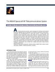
BASIC PRINCIPLES OF HOMING GUIDANCENoiseLOSSeeker++ + + – – Gimbal angle1/s 1/sReceiver1LOS rate pick<strong>of</strong>f m 1 s .cLOS rate estimate^1 . f s + 1<strong>Guidance</strong> PNfilter<strong>Guidance</strong> computera McCommandedaccelerationNV cG FC (s).++Gimbal servoDish rateGimbal controlRate gyro1 .+–Flight controlsystem.Body attitude ratea A s + 1v mAchievedaccelerationBody rateaerodynamicsFigure 5. Simplified planar model <strong>of</strong> a traditional LOS rate reconstruction approach that directly supplies an LOS rate measurementto the guidance computer. Note that the LOS rate pick<strong>of</strong>f is assumed to be proportional to the boresight errormeasurement. <strong>The</strong> measured LOS rate is subsequently filtered to mitigate measurement noise and then applied to the PNhoming guidance law.Moreover, the transfer function from commanded acceleration(from the guidance law) to missile body rate (ċ)is approximated by the following aerodynamic transferfunction, where t Ais the turning rate time constant andv mis missile velocity:o A s + 1= .a vcm(26)In this approach, the fact that the LOS rate is embeddedin the tracking error ( m) is exploited. As illustrated, aLOS rate estimate is derived by appropriately filteringthe receiver tracking error scaled by the seeker tracklooptime constant.Other approaches can be used to derive LOS rate forhoming guidance purposes; these are generally referredto as either LOS reconstruction or LOS rate reconstruction.We next outline three alternative techniques (twoLOS reconstructions and one LOS rate reconstruction).LOS ReconstructionAs shown in Fig. 3, LOS reconstruction works toconstruct a measured LOS, l m, in an inertial frame <strong>of</strong>reference. <strong>The</strong> measured LOS then is filtered (via anappropriate guidance filter) to derive an estimate <strong>of</strong> LOSrate for guidance purposes. Two different LOS reconstructionapproaches are as follows: 91. Integrate the seeker gyro output and sum it with themeasured tracking error. A block diagram <strong>of</strong> thisapproach is shown in Fig. 6. Mathematically, thisapproach can be expressed as Eq. 27:l m= m+ # . dt . (27)2. Integrate the output <strong>of</strong> the missile body rate gyro,obtained from the missile IMU, and sum the integratedIMU gyro output together with the seekergimbal angle and the measured tracking error. Weillustrate this approach in the block diagram shownin Fig. 7. This approach is expressed mathematicallyas shown in Eq. 28:l m= m+ b + # ċ dt . (28)From Fig. 3, it is clear that the two concepts are algebraicallyequivalent in the absence <strong>of</strong> noise and assumingperfect instruments (no gyro biases, drift, etc.); however,in practice, this is not the case. Moreover, we note that,in general, the guidance filters for the two approachesare not necessarily the same (e.g., for the simplified guidancefilters shown in the figures, the filter time constants,represented by t f, are not necessarily the same).<strong>The</strong> fundamentals <strong>of</strong> guidance filtering will be discussedin the companion article in this issue “<strong>Guidance</strong> FilterFundamentals.” It is shown in Ref. 9 that the two LOSreconstruction approaches can yield significantly differentresults when noise and imperfect instrumentsare used. How these differences manifest themselvesdepends on the quality <strong>of</strong> the measurements and instrumentsthat are used.LOS Rate ReconstructionA guidance signal also can be generated by differentiatingthe tracking error and adding it tothe seeker rate gyro output. For practical purposes,taking the derivative <strong>of</strong> the tracking error is accom-JOHNS HOPKINS APL TECHNICAL DIGEST, VOLUME 29, NUMBER 1 (2010)31
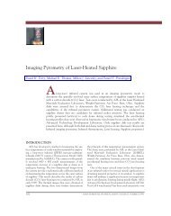
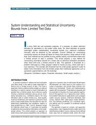
BASIC PRINCIPLES OF HOMING GUIDANCENoiseLOSSeeker++ + + – – Gimbal angle1/s 1/s.Gimbal servo+Dish rate+LOS rate pick<strong>of</strong>f. . m s m + D s + 1+1 s . .c+Gimbal control – .Receiver1Rate gyro1mLOS rate estimate^1 . a Mc f s + 1NV c<strong>Guidance</strong> PN Commandedfilteracceleration<strong>Guidance</strong> computerFlight control G FC (s)systemAchievedaacceleration. A s + 1Body attitude rate v mBody rateaerodynamicsFigure 8. Simplified planar model <strong>of</strong> an alternate LOS rate reconstruction approach that can directly supply an LOS rate measurement tothe guidance computer. Note that the LOS rate reconstruction differences between this figure and Fig. 5. As before, the measured LOS rate issubsequently filtered to mitigate measurement noise and then applied to the PN homing guidance law.1. It must convey the energy with minimum loss.2. It must convey the energy with minimum distortion,particularly angular distortion because this creates aparasitic feedback loop that can have a significantnegative impact on guidance performance (discussedin more detail below).3. It must have minimum aerodynamic drag.4. It must have satisfactory physical properties, suchas sufficient strength, resistance to thermal shock(from rapid aerodynamic heating), resistance torain erosion at high speeds, and minimum waterabsorption.111/2L/D 1/2Ideal electromagnetically5L/D 5Ideal aerodynamicallyL/D 3Compromise radomeFigure 9. Three possible radome shapes are illustrated. Forminimum angular distortion, a hemispherical shape (or hyperhemisphericalshape as in a ground-based radar) would be idealelectromagnetically (upper left), but the drag penalty is excessive.From an aerodynamic perspective, the lower left radome shape ispreferable, but it tends to have significant angular distortion characteristics.<strong>The</strong> tangent-ogive shape (on the right) is a typical compromisedesign. Nevertheless, some missiles use much blunterdome designs despite the drag penalty. L/D, lift-to-drag ratio.13As an example, Fig. 9 illustrates three conceivableradome shapes. <strong>The</strong> tangent-ogive shape (on the right)is a typical compromise design.<strong>Guidance</strong> System Design Challenges<strong>The</strong>re are a significant number <strong>of</strong> challenges todesigning guidance systems: the design must provide thedesired performance while remaining robust to a multitude<strong>of</strong> error sources, limited control system bandwidth,and inherent system nonlinearities. Some <strong>of</strong> these challengesare summarized below.1. <strong>The</strong> root-mean-square final miss distance from alldeleterious noise sources must be minimized.2. <strong>Guidance</strong> system stability must be maintained in theparasitic feedback loop (as mentioned above, this iscaused by angular distortion <strong>of</strong> the radome/irdome).Radome angular distortion, in particular, is a keycontributor to final miss distance but is consideredseparately from other noise sources as its impact onguidance system stability is substantial.3. System nonlinearities must be avoided as muchas possible; e.g., seeker gimbal angle and gyro ratesaturations must be avoided, as should commandingmissile acceleration beyond what is physicallyrealizable by the missile.Contributors to Final Miss DistanceWith respect to guidance challenge item 1 above,there are a number <strong>of</strong> contributors to final miss distance(other than angular distortion <strong>of</strong> the radome/irdome).For example, in either an RF or IR guidance system, measurementnoise from the various instruments (onboardJOHNS HOPKINS APL TECHNICAL DIGEST, VOLUME 29, NUMBER 1 (2010)33
BASIC PRINCIPLES OF HOMING GUIDANCERadome bse(radome error)bseApparent LOSTrue LOSSeeker centerline (Seeker gimbal angle)Missile body axis bser (slope)Using the fact that the seeker dish angle can be writtenas = c + b, we obtain the following expression for thederivative <strong>of</strong> the measured tracking error:. m= l . – (1 – r)ḃ – ċ . (33)Using Eq. 33, we can modify the block diagram shown inFig. 5 to include the dome distortion effect (via Eq. 33).<strong>The</strong> result is shown in Fig. 11. Clearly, the boresight errorcreates another signal path in the missile guidance loop.To obtain an alternate view <strong>of</strong> this parasitic loopand how it can affect guidance performance, we revisitEq. 32. Referring to Fig. 3, we note that the seekergimbal angle can be expressed as b = – c and thatthe measured LOS can be written as l m= + m. Alsonoting that it is typical for r
Vc /v M0.350.300.250.200.150.100.0500Boundary = 0.170.01Navigation ratio: N = 3Effective navigation ratio: Ñ (r) = N/(1 + rNV c /v M )Unstable region: Ñ (r ) N/(1 + rNV c /v M ) 20.020.03V c /v M = 3V c /v M = 2V c /v M = 1Stable region: Ñ (r ) N/(1 + rNV c /v M ) > 20.04 0.05 0.06Radome slope r (rads)Figure 13. For a navigation ratio <strong>of</strong> 3, the effect <strong>of</strong> positive radome boresight error slope (r)for increasing ratios <strong>of</strong> closing velocity over missile velocity is shown. To maintain guidancestability, the effective navigation ratio must remain greater than 2.Closest point <strong>of</strong> approach (ft)109876543210–0.10acceleration limit is more a result <strong>of</strong> maximum angle-<strong>of</strong>attacklimitations. In either case, the missile guidanceand control system design must take the accelerationlimits into account. <strong>The</strong> most significant implicationis that the commanded acceleration from the guidancesystem must be hard-limited so as not to exceedthe acceleration limits <strong>of</strong> the missile, which also implies0.07 = 0.5 s –1 = 0.3 s –1 = 0.1 s –1 = 0.4 s –1 = 0.2 s –1–0.05 0 0.05Radome error slope (%)0.100.15Figure 14. This plot illustrates the miss performance <strong>of</strong> PNversus radome boresight error slope. <strong>The</strong> results were derived byusing a planar Simulink model assuming no error sources asidefrom radome error. Each curve represents the results using anautopilot with specified time constant t. A larger time constantindicates a larger lag in the missile response to accelerationcommands.0.080.090.10BASIC PRINCIPLES OF HOMING GUIDANCEthat the flight control system(autopilot) must be designed toproduce minimum overshoot toan acceleration step command.If/when the guidance commandsaturates, the missile guidanceloop is essentially opened. If guidancecommand saturation persistslong enough, and if this persistentsaturation occurs near intercept, asignificant final miss distance canresult.Missile seeker systems also areprone to nonlinear saturation,which can have significant deleteriouseffects on overall guidanceperformance. For example,on gimbaled platforms, the seekergimbal angle can saturate undercertain stressing conditions (e.g.,while pursuing a highly maneuveringtarget). If this saturationoccurs, the guidance loop haseffectively become open and, if this occurs near intercept,significant final miss distance can occur.<strong>Guidance</strong> Command PreservationThree-dimensional guidance laws usually generatea guidance command vector without consideration tohow the missile interceptor will effectuate the specifiedmaneuver. For example, it is typical for a guided missileto (i) have no direct control over its longitudinal acceleration(e.g., axial thrust is not typically throttleable)and (ii) maneuver in the guidance direction (specifiedby the guidance law) by producing acceleration normalto the missile body. <strong>The</strong>refore, the question naturallyarises as to how a three-dimensional guidance command,specified by the guidance law without consideration<strong>of</strong> the aforementioned constraints, can beachieved by maneuvering the missile perpendicular tothe missile centerline. We shall refer to this process asguidance command preservation.In Ref. 1, two guidance command preservationtechniques are developed. <strong>The</strong> first approach, referredto here as GCP1, is further elaborated in Ref. 12. <strong>The</strong>second guidance command preservation technique(GCP2) is a minimum norm solution. As such, GCP2could (theoretically) provide savings in commandedacceleration (or fuel use in exoatmospheric applications)as compared with the first method. <strong>The</strong> GCP1technique is discussed here.GCP1 TechniqueTo describe this guidance command preservationtechnique, we refer to Fig. 15 and make the followingJOHNS HOPKINS APL TECHNICAL DIGEST, VOLUME 29, NUMBER 1 (2010)37
N. F. PALUMBO, R. A. BLAUWKAMP, and J. M. LLOYD = cos –1a c a M Missileacceleration bodydefinitions: _ 1 ris a unit vector along the missile–targetLOS, _ 1 xis a unit vector along the missile centerline(missile longitudinal axis), _ a cis the guidance lawacceleration_command perpendicular to the LOS, andaM = [a Mxa Mya Mz] T is the achieved missile accelerationvector comprising components in the x/y/z axes.Two component directions serve as a basis for thedevelopment <strong>of</strong> GCP1: the direction <strong>of</strong> the LOS ( _ 1 r)and the commanded guidance direction ( _ 1 ac= _ a c/ _ a c).Assuming perfect interceptor response to commandedacceleration (i.e., no lag from commanded to achievedacceleration), the (guidance preserved) missile accelerationcan be expressed as follows:_aM = k 1_1r + k 2_1ac . (43)<strong>The</strong> design parameters, k 1and k 2, are determined subjectto the following constraints:a : 1 = aa : 1 = aM x MxMa cc.(44)Equations 44 analytically embody the following constraints:(i) the missile does not control longitudinalacceleration and (ii) the component <strong>of</strong> missile accelerationalong the guidance direction, _ 1 ac, must be thatspecified by the guidance law ( _ a c). Using Eqs. 43 and44 and given _ 1 r• _ 1 ac= 0 (i.e., the guidance commandis perpendicular to the LOS), an expression for commandedmissile acceleration that will preserve the guidancecommand is given in Eq. 45:aGLaMx – ac : 1x= e o 1 a .1 : 1r +c(45)rx1 r1 xLOSMissilecenterlinea M a c PN guidance command LOSa M Achieved missile accelerationFigure 15. GCP1. <strong>The</strong> LOS vector is shown along with the commandedacceleration from PN, which is perpendicular to the LOS.Also, the missile centerline (direction <strong>of</strong> the missile nose) andachieved missile acceleration vector are superimposed. <strong>The</strong> guidancepreservation problem is to achieve missile acceleration thathas the component along the guidance direction as specified bythe guidance law.Equation 45 is derived independently from any particularcoordinate system. It is easy to mechanize the expressionin Eq. 45 such that the computations are carried outin the missile body frame (B). We first note that missileacceleration resolved into the missile body frame cana MBBMxBMyB TMzbe expressed as = [ a a a ] and that thebody-referenced unit vector along the longitudinal axis<strong>of</strong> the missile can be written as _ 1B x= [1 0 0] T . <strong>The</strong>quantities _ 1 r(LOS unit vector) and _ a c(guidance lawcommand) usually are defined with respect to a guidancereference _ frame. To reflect this fact, we expressthem as 1G r= [1 0 0] T _and acG= [0 aG cya G cz] T .Here, the superscript denotes the frame <strong>of</strong> referencewith which the quantities are currently expressed; inthis case, the guidance reference frame (G). Thus, wemust resolve all guidance frame quantities into themissile body frame through the coordinate transformationCB G_= c B G(i, j), i, j = 1, 2, 3; for example, 1rB=C B G[1 0 0] T ≡ [c B G(1, 1) c B G(2, 1) c B G(3, 1)] T . Note thatif we fix the guidance frame at the start <strong>of</strong> terminalhoming (t = 0), we obtain the transformation CG I=C B I(C BS t = 0). <strong>The</strong> inertial-to-body transformation, C B I,comes from the IMU, and CSBmay be computed via theseeker gimbals (see Eq. 23). Subsequently, CB G= C B I(C G I) T .If necessary, the guidance frame may be updated frominstant to instant, but this adds computational complexity.Given that CB Gis available, the following mechanization<strong>of</strong> Eq. 45 is possible:aBGCBBaMx– ac: 1x= rBaBfrBB p +c: 1xR V RB c ( 1, 1)aa – a S W SMx cx/ f c ( 2, 1)aB pSW + ScG( 1, 1)SSc( 3, 1)W SaT X TBB G B G B cxBBG B cyBczVWW .WWX(46)In Eq. 46, [aBcxaB cya B cz] T is the guidance commandvector expressed in the missile body frame. This mechanizationwill generate guidance commands in the missilebody frame that satisfy the constraints in Eq. 44.MIDCOURSE GUIDANCESo far, this article has been chiefly concerned withthe requirements <strong>of</strong> terminal homing, wherein targetmeasurements are provided by one or more onboard terminalsensors and minimizing miss distance at interceptis the primary objective. For completeness’ sake, we nowwill briefly discuss issues and requirements associatedwith the midcourse phase <strong>of</strong> flight.During the midcourse guidance phase <strong>of</strong> a multimodemissile (see Fig. 16), target tracking is performedby an external sensor to support the engagement. 6 Externaltracking relaxes the requirements for the onboardsensor to point at the target and detect it at large ranges.38JOHNS HOPKINS APL TECHNICAL DIGEST, VOLUME 29, NUMBER 1 (2010)
BASIC PRINCIPLES OF HOMING GUIDANCEBoost (Inertial)Midcourse (Guided)Terminal (Guided)• Onboard inertial guidanceprocessing• Safe launch/separation• Boost to flight speed• Establish flight path• Arrive at pre-calculated pointat end <strong>of</strong> boost (EOB)EOBIn-flighttargetupdatesHandoverSeekeracquisitionPredicted interceptpoint (PIP)EndgameFuzing• Off-board target tracking• Onboard or <strong>of</strong>f-board guidance processing• One or more additional booster stages• Maintain a desired course• Bring the missile “close” to the target• Trajectory shaping/energy management• Can be active endo through exo• Onboard seeker/guidance processing• Requires high degree <strong>of</strong> accuracy and fastcommand response• Can require maneuvering to maximumcapability to intercept fast-moving,evasive targets• Active endo or exo, typically not bothPre-launch• Targeting• Targeting• Engageability • Engageability determinationdetermination• Missile • Missile initializationinitializationFigure 16. Missile guidance phases. <strong>The</strong> weapon control system first decides whether the target is engageable. If so, a launch solution iscomputed and the missile is initialized, launched, and boosted to flight speed. Inertial guidance typically is used during the boost phase<strong>of</strong> flight during which the missile is boosted to flight speed and roughly establishes a flight path to intercept the target. Midcourse guidanceis an intermediate flight phase whereby the missile receives information from an external source to accommodate guidance to thetarget. During the midcourse phase, the missile must guide to come within some reasonable proximity <strong>of</strong> the target and must providedesirable relative geometry against a target when seeker lock-on is achieved (just prior to terminal homing). <strong>The</strong> terminal phase is thelast and, generally, the most critical phase <strong>of</strong> flight. Depending on the missile capability and the mission, it can begin anywhere fromtens <strong>of</strong> seconds down to a few seconds before intercept. <strong>The</strong> purpose <strong>of</strong> the terminal phase is to remove the residual errors accumulatedduring the previous phases and, ultimately, to reduce the final distance between the interceptor and target below some specified level.However, the accuracy <strong>of</strong> sensors generally degrades withdistance. It is therefore unlikely that a stand<strong>of</strong>f sensorwill have sufficient accuracy in tracking both the targetand missile to guide a missile close enough for intercept.<strong>The</strong> objectives during midcourse guidance are insteadto guide the missile to a favorable geometry with respectto the target for both acquisition by the onboard sensorand handover to terminal homing.During the midcourse guidance phase, the weaponcontrol must provide information to the missile aboutthe threat. This information may be nothing more thanestimates <strong>of</strong> the threat kinematic states or may include apredicted intercept point (PIP). Predictions <strong>of</strong> the futuretarget trajectory, whether calculated on board the missileor by the weapon control system, are based on assumptions<strong>of</strong> what maneuvers the threat is likely to do andwhat maneuvers are possible for the threat to perform.<strong>The</strong>se assumptions typically are sensitive to the type <strong>of</strong>threat assumed but may include booster pr<strong>of</strong>iles, aerodynamicmaneuverability, or drag coefficient(s). <strong>The</strong> PIPis therefore highly prone to errors. Occasional in-flighttarget updates may be needed to improve the accuracy <strong>of</strong>the PIP before handover to terminal homing.A form <strong>of</strong> PN might be used during the midcourseguidance phase but generally results in excessive slowdown,however, as a result <strong>of</strong> the added atmosphericdrag generated by maneuvers. Instead, it is desirable touse a guidance law that will maximize missile velocityduring the endgame such that missile maneuverabilitywill be maximized when called for during stressingendgame maneuvers. Lin 11 describes an approach thatapplies optimal control theory to derive efficient, analyticalsolutions for a guidance law that approximatelymaximizes the terminal speed while minimizing themiss distance. <strong>The</strong> guidance commands are expressed inthe form given in Eq. 47:K1 a V2 K2 sin( ) cos( ) – V2= sin( ) . (47)RRHere, V is the missile speed, R is the range to thePIP, is the angle difference between the current anddesired final velocity, and s is the heading error. <strong>The</strong>first term shapes the trajectory to achieve a desiredapproach angle to the intercept, and the second termminimizes miss. <strong>The</strong> gains K 1and K 2are time-varyingJOHNS HOPKINS APL TECHNICAL DIGEST, VOLUME 29, NUMBER 1 (2010)39
N. F. PALUMBO, R. A. BLAUWKAMP, and J. M. LLOYDand depend on flight conditions, booster assumptions,and other factors. A critical component <strong>of</strong> implementingthis law is computing an accurate estimate <strong>of</strong> time-to-gowhen the missile is still thrusting, which depends on thecomponent <strong>of</strong> missile acceleration along the LOS. <strong>The</strong>guidance calculations can be made on board the missileor <strong>of</strong>f board, with acceleration commands passed fromthe weapon control system to the missile where they areconverted to body coordinates.For exoatmospheric flight, drag is no longer an issue,but long flight times will result in curved trajectories asa result <strong>of</strong> gravity. From the current position, the Lambertsolution (see Ref. 7 for a simple synopsis) definesthe necessary current velocity to reach a terminalintercept point at a given time. A guidance law can be“wrapped around” the Lambert solution to progressivelysteer the missile velocity vector to align with the Lambertvelocity. <strong>The</strong>n either thrust termination or a slowdownmaneuver can be used to match the magnitude <strong>of</strong>the velocity <strong>of</strong> the Lambert solution when the missilebooster burns out.CLOSING REMARKS<strong>The</strong> key objective <strong>of</strong> this article was to provide arelatively broad conceptual foundation with respectto homing guidance but also <strong>of</strong> sufficient depth toadequately support the articles that follow. First, wediscussed handover analysis and emphasized that thedisplacement error between predicted and true targetposition, _ e, can be decomposed into two components:one along ( _ e ) and one perpendicular to ( _ e ⊥ ) the predictedLOS. Thus, because the relative velocity isalong the LOS to the predicted target location, the erroralong this direction alters the time <strong>of</strong> intercept but doesnot contribute to the final miss distance. It is the errorperpendicular to the LOS that must be removed bythe interceptor after transition to terminal homing toeffect an intercept.Next, we developed a classical form <strong>of</strong> PN and notedthat a primary advantage <strong>of</strong> PN, contributing to its longevityas a favored guidance scheme over the last fivedecades, is its relative simplicity <strong>of</strong> implementation. Infact, the most basic PN implementations require lowlevels <strong>of</strong> information regarding target motion as comparedwith other, more elaborate schemes, thus simplifyingonboard sensor requirements. Moreover, it hasproven to be relatively reliable and robust. This particular(and somewhat unique) treatment <strong>of</strong> PN was takenfrom a 1980 APL memorandum written by Alan J. Pue. 1We also discussed how PN can be mechanized for guidedmissile applications, with a focus on LOS reconstructionand guidance command preservation. With respect tohoming guidance, we itemized the primary contributorsto guidance performance degradation that can ultimatelylead to unacceptable miss distance.<strong>The</strong> onboard missile seeker has a limited effectiverange beyond which target tracking is not possible. Tosupport engagements that initially are beyond such arange, midcourse guidance is used to bring the missilewithin the effective range <strong>of</strong> the seeker. Thus, in contrastto terminal homing, during the midcourse guidancephase <strong>of</strong> flight, the target is tracked by an externalsensor and information is uplinked to the missile. <strong>The</strong>key objectives during midcourse guidance are to guidethe missile to a favorable geometry with respect to thetarget for both acquisition by the onboard missile targetingsensor and to provide acceptable handover to terminalhoming. Many <strong>of</strong> the terminal homing conceptsdiscussed here and in the subsequent articles on modernguidance and guidance filtering in this issue also areapplicable to developing midcourse guidance policies.Thus, mainly for completeness, we briefly introduced theproblem <strong>of</strong> midcourse guidance.REFERENCES1 Pue, A. J., Proportional Navigation and an Optimal-Aim <strong>Guidance</strong> Technique,Technical Memorandum F1C(2)80-U-024, JHU/APL, Laurel,MD (7 May 1980).2 Ben-Asher, J. Z., and Yaesh, I., Advances in Missile <strong>Guidance</strong> <strong>The</strong>ory,American Institute <strong>of</strong> Aeronautics and Astronautics, Reston, VA(1998).3 Locke, A. S., <strong>Principles</strong> <strong>of</strong> Guided Missile Design, D. Van NostrandCompany, Princeton, NJ (1955).4 Shneydor, N. A., Missile <strong>Guidance</strong> and Pursuit: Kinematics, Dynamicsand Control, Horwood Publishing, Chichester, England (1998).5 Shukala, U. S., and Mahapatra, P. R., “<strong>The</strong> Proportional NavigationDilemma—Pure or True?” IEEE Trans. Aerosp. Electron. Syst. 26(2),382–392 (Mar 1990).6 Witte, R. W., and McDonald, R. L., “Standard Missile: <strong>Guidance</strong>System Development,” <strong>Johns</strong> <strong>Hopkins</strong> APL Tech. Dig. 2(4), 289–298(1981).7 Zarchan, P., Tactical and Strategic Missile <strong>Guidance</strong>, 4th Ed., AmericanInstitute <strong>of</strong> Aeronautics and Astronautics, Reston, VA (1997).8 Stallard, D. V., Classical and Modern <strong>Guidance</strong> <strong>of</strong> <strong>Homing</strong> InterceptorMissiles, Raytheon Report D985005, presented at an MIT Dept. <strong>of</strong>Aeronautics and Astronautics seminar (Apr 1968).9 Miller, P. W., Analysis <strong>of</strong> Line-<strong>of</strong>-Sight Reconstruction Approaches forSM-2 Block IVA RRFD, Technical Memorandum F1E(94)U-2-415,JHU/APL, Laurel, MD (22 Dec 1994).10 Nesline, F. W., and Zarchan, P., “Line-<strong>of</strong>-Sight Reconstruction forFaster <strong>Homing</strong> <strong>Guidance</strong>,” AIAA J. Guid. Control Dyn. 8(1), 3–8(Jan–Feb 1985).11 Lin, C. F., Modern Navigation, <strong>Guidance</strong>, and Control Processing, PrenticeHall, Englewood Cliffs, NJ (1991).12 Abedor, J. L., Short Range Anti-Air Warfare Engagement Simulation,Technical Memorandum F1E(86)U-3-031, JHU/APL, Laurel, MD(10 Nov 1986).40JOHNS HOPKINS APL TECHNICAL DIGEST, VOLUME 29, NUMBER 1 (2010)
BASIC PRINCIPLES OF HOMING GUIDANCE<strong>The</strong> AuthorsNeil F. Palumbo is a member <strong>of</strong> APL’s Principal Pr<strong>of</strong>essional Staff and is the Group Supervisor <strong>of</strong> the <strong>Guidance</strong>,Navigation, and Control Group within the Air and Missile Defense Department (AMDD). He joined APL in 1993after having received a Ph.D. in electrical engineering from Temple University that same year. His interests includecontrol and estimation theory, fault-tolerant restructurable control systems, and neuro-fuzzy inference systems.Dr. Palumbo also is a lecturer for the JHU Whiting School’s Engineering for Pr<strong>of</strong>essionals program. He is a member<strong>of</strong> the Institute <strong>of</strong> Electrical and Electronics Engineers and the American Institute <strong>of</strong> Aeronautics and Astronautics.Ross A. Blauwkamp received a B.S.E. degree from Calvin College in 1991 and an M.S.E. degree from the University<strong>of</strong> Illinois in 1996; both degrees are in electrical engineering. He is pursuing a Ph.D. from the University <strong>of</strong> Illinois.Mr. Blauwkamp joined APL in May 2000 and currently is the supervisor <strong>of</strong> the Advanced Concepts and SimulationTechniques Section in the <strong>Guidance</strong>, Navigation, and Control Group <strong>of</strong> AMDD. His interests include dynamic games,nonlinear control, and numerical methods for control. He is a member <strong>of</strong> the Institute <strong>of</strong> Electrical and ElectronicsEngineers and the American Institute <strong>of</strong> Aeronautics and Astronautics. Justin M. Lloyd is a member <strong>of</strong> the APL SeniorPr<strong>of</strong>essional Staff in the <strong>Guidance</strong>, Navigation, and Control Group <strong>of</strong> AMDD. He holds a B.S. in mechanical engineeringfrom North Carolina State University and an M.S. in mechanical engineering from Virginia Polytechnic Instituteand State University. Currently, Mr. Lloydis pursuing his Ph.D. in electrical engineeringat <strong>The</strong> <strong>Johns</strong> <strong>Hopkins</strong> University. He joinedAPL in 2004 and conducts work in optimization;advanced missile guidance, navigation, and control;and integrated controller design. For furtherinformation on the work reported here, contactNeil Palumbo. His email address is neil.palumbo@Neil F. Palumbo Ross A. Blauwkamp Justin M. Lloyd jhuapl.edu.<strong>The</strong> <strong>Johns</strong> <strong>Hopkins</strong> APL Technical Digest can be accessed electronically at www.jhuapl.edu/techdigest.JOHNS HOPKINS APL TECHNICAL DIGEST, VOLUME 29, NUMBER 1 (2010)41