CP10K Instructions - Gardner Bender
CP10K Instructions - Gardner Bender
CP10K Instructions - Gardner Bender

Create successful ePaper yourself
Turn your PDF publications into a flip-book with our unique Google optimized e-Paper software.
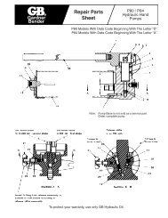
10,000 lb. Cable PullerInstruction Sheet<strong>CP10K</strong>SAFETY ISSUESIMPORTANT – USER SAFETY ANDPROTECTION: In setting up systems tofit your operations, care must be takento select the proper components anddesign to insure that all safety measureshave been taken to avoid the risk ofpersonal injury and property damagefrom your application or system.GARDNER BENDER is notRESPONSIBLE FOR DAMAGE ORINJURY CAUSED BY UNSAFE USE,MAINTENANCE OR THE APPLICATIONOF ITS PRODUCTS. Please contact<strong>Gardner</strong> <strong>Bender</strong> for guidance whenyou are in doubt as to the proper safetyprecautions to be taken in designing andsetting up your particular application.Technical Support # 1-800-624-4320.1.0 Safety Symbol Definitions . . . . . . . . . . . . . . . . . 22.0 Warning Labels on Product. . . . . . . . . . . . . . . . 23.0 Key Safety Information . . . . . . . . . . . . . . . . . . . 24.0 Electrical Safety Information . . . . . . . . . . . . . . . 25.0 Safe Pulling Guidelines . . . . . . . . . . . . . . . . . 2-36.0 Puller Specifications . . . . . . . . . . . . . . . . . . . . . 37.0 Parts Identification . . . . . . . . . . . . . . . . . . . . . . 48.0 Pulling Preparation . . . . . . . . . . . . . . . . . . . . . . 59.0 Setting Up the Machine . . . . . . . . . . . . . . . . . . . 59.1 Pulling Upward . . . . . . . . . . . . . . . . . . . 5-6www.gardnerbender.com9.2 Pulling Downward . . . . . . . . . . . . . . . . . 6-79.3 Pulling Sideways. . . . . . . . . . . . . . . . . . . . 710.0 Rope Path General Guidelines . . . . . . . . . . . . . . . . . 711.0 Operating <strong>Instructions</strong>. . . . . . . . . . . . . . . . . . 7-812.0 Transporting the Machine . . . . . . . . . . . . . . . . . 813.0 Maintenance . . . . . . . . . . . . . . . . . . . . . . . . . . . 814.0 Additional Cable Pulling Accessories. . . . . . . . 8PO Box 3241 Milwaukee, WI 53201-3241 | 414.352.4160 | fax 414.352.23776615 Ordan Drive | Mississauga, Ontario L5T 1x2 | 905.564.5749 | fax 905.564.0305IS-164 | September 20091
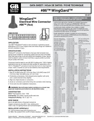
The instruction manual and labels applied to the product provideinformation for avoiding injury or death from unsafe practicesrelated to setting up and operating this machine. It is critical that allpersonnel involved with the use of this machine understand thesehazards and unsafe practices. The three levels (Danger, Warning,and Caution) define the severity of the hazard.DANGER: Immediate hazards that if not avoided WILL resultin severe injury or death.WARNING: Serious injury or death COULD occur if properattention is not observed.CAUTION: Injury or property damage MAY occur if properattention is not observed.The product has safety related labels securely adhered to itin several locations. They serve to highlight the areas of thismachine that have the potential to cause injury if the operatordoes not use caution. The labels include internationallyrecognized ! symbols that are described below.! Read and understand the instruction sheet beforesetting up or operating this machine.!!1.0 SAFETY SYMBOL DEFINITIONS2.0 WARNING LABELSON PRODUCTBody parts are in danger of being crushed bymoving or moveable parts.Body parts are in danger of being entangled in rope.Read instruction sheet before operation.12. Do not wear jewelry or loose-fitting clothes. Long hair, clothing,body parts and gloves should be clear of moving parts.13. Always use all personal safety equipment, including eyeprotection and a hard hat.14. Do not wrap rope around legs, arms or torso of body.15. Do not plug Power Cord directly into power source. PowerCord must be plugged into the Footswitch.4.0 ELECTRICAL SAFETYINFORMATIONGroundingA three pronged grounded plug is included in the Footswitchand must be plugged into a three hole, properly wired groundedsocket. Do not use a three prong to two prong adaptor. Neverconnect the ground wire to a live terminal.Extension Cords1. Using an extension cord reduces the voltage supply to theMotor. Select the appropriate wire size for extension cordlength from Table 1.2. Only extension cords with the suffix W-A following the cordtype designation are allowed for outdoor use.3. Extension cords must have a three prong plug and threeprong receptacles.4. Do not use machine if extension cord has been damaged orabused.Table 1. Extension Cord Minimum Wire Gauge GuideTotal Amps: 0-5.0 5.1-7.0 7.1-12.0 12.1-16.0 16.1-20.0Length (ft.) Wire Gauge Wire Gauge Wire Gauge Wire Gauge Wire Gauge25 18 18 16 14 1250 18 16 14 12 1075 18 14 12 10 8100 18 12 10 8 8150 16 12 8 8 6200 16 10 8 6 43.0 KEY SAFETY INFORMATION5.0 SAFE PULLINGGUIDELINES1. Do not use the cable puller for any other purpose orapplication beyond its intended use. It is intended for pullingwire or cable through fixed conduit, with the conduit adaptorengaged in the conduit and fastened to the cable puller.2. Do not operate the cable puller in poorly lit areas.3. Do not exceed the maximum rated 10,000 lbs. pulling force.4. Inspect all cable puller components prior to operation.5. Keep the pull rope away from the operator’s feet. Gather thetailing rope in an area where the operator or crew cannotbecome entangled.6. Never stand directly under a vertical pull or directly in linewith pull rope under tension.7. Never use general purpose rope; always use double braidedpolyester rope and inspect the rope for damage after eachpull. Do not use damaged rope for pulling cable.8. Do not allow the rope coils to overlap on the Capstan.9. Keep bystanders away from operations. Distractionsincrease chances of injury.10. Do not use the cable puller while under the influence ofdrugs, alcohol or medication.11. Do not operate near water or other liquids.DANGER1. Never expose machine to wet conditions due to electric shock.2. Do not use or store this machine near exposed live circuits oroverhead wires.3. Do not use a damaged or worn extension or Footswitch cord.FAILURE TO OBSERVE THESE DANGERS WILL RESULT INSEVERE INJURY OR DEATHAPPLICATIONWARNING1. The maximum pulling capacity must not be exceeded.2. Use the recommended size rope for pulling load. See6.0 Puller Specifications.3. Rope may beak or pulling grip may come loose under tension.Stand in the safe zone which is at least 30 degrees to eitherside of rope. (See Figure 1)4. Rope must be replaced if the strands are worn or cut.5. Use the correct size Conduit Adaptor.FAILURE TO OBSERVE THESE WARNINGS COULD RESULTIN SEVERE INJURY OR DEATH2
SAFELooking Down from Above30°DANGER30°SAFEFigure 1. Stand in Safe ZoneCAUTION1. Inspect machine to be free of all rust, dirt and grit.2. Eye protection, hard hats and all personal safety equipment needs to be worn.3. Power Cord must be plugged into Footswitch.4. Do not allow rope to rub anywhere other than pulley rollers and Capstan.5. Do not wear loose fitting clothes.FAILURE TO OBSERVE THESE CAUTIONS MAY RESULT IN SEVERE INJURY OR DEATH6.0 PULLER SPECIFICATIONSTable 2. Puller SpecificationsWeightShipping DimensionsProduct DimensionsMotorPulling ForceRopeShipping Weight455 lbs.Product Weight385 lbs.Pallet66" wide x 36" deepOverall Height (includes pallet): 44"Wheel Span 28"Length 61"Height 39"Volts115 VDCCurrent14 ampsType1-phaseMax Capacity (Intermittent Duty)10,000 lbs.Continuous8,000 lbs.Green & Yellow Zone on Pull Meter3/4" double braided polyester ropeRed Zone on Pull Meter7/8" double braided polyester ropeCAUTION1. Inspect pulling rope. Do not use if damaged.2. Do not allow rope to rub anywhere other than pulley rollers and Capstan.3. Do not exceed capacity of Motor force. Observe Pull Meter for reference.FAILURE TO OBSERVE THESE CAUTIONS MAY RESULT IN DAMAGING MACHINE Motor OR SEVERE INJURY3
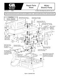
7.0 PARTS IDENTIFICATION1. Steering Handles2. Caster Wheels & Brakes3. Hydraulic Pump4. Main Boom5. Boom-A6. Boom-B7. Boom-A Lock Pin8. Pulley-A Housing9. Boom-B Lock Pin10. Boom-B Extension11. Boom-B ExtensionLock Pin12. Pulley-B Housing13. Pulley-B HousingLock Pin14. Pull Orientation Pivot15. Pull Orientation Pin16. Conduit Adaptors17. Power Cord18. Footswitch19. Pull Meter & Switch Box20. Capstan21. Motor22. Pin Clips198146151013 51112742021223191718 1624
8.0 PULLING PREPARATION9.0 SETTING UP THE MACHINEIf all cable diameters within the bundle are the same, select yourgrip from Table 3.Table 3. Pulling Grip Guide With Known Cable DiameterNumber of Cables in Each Grip and Diameter RangeIndividual Cable DiametersGripDiameter2 3 4 5 Range.30 – .38 .25 – .31 .22 – .27 .19 – .24 .50 – .61.38 – .44 .31 – .36 .27 – .31 .24 – .29 .62 – .74.44 – .59 .36 – .49 .31 – .42 .29 – .38 .75 – .99.59 – .75 .49 – .63 .42 – .54 .38 – .48 1.00 – 1.24.75 – .90 .63 – .76 .54 – .65 .48 – .58 1.25 – 1.49.90 – 1.07 .76 – .89 .65 – .77 .58 – .67 1.50 – 1.741.07 – 1.22 .89 – 1.02 .77 – .88 .67 – .77 1.75 – 1.991.22 – 1.53 1.02 – 1.28 .88 – 1.10 .77 – .96 2.00 – 2.491.53 – 1.83 1.28 – 1.53 1.10 – 1.32 .96 – 1.16 2.50 – 2.991.83 – 2.14 1.53 – 1.79 1.32 – 1.54 1.16 – 1.35 3.00 – 3.492.14 – 2.44 1.79 – 2.05 1.54 – 1.76 1.35 – 1.54 3.50 – 3.992.44 – 2.75 2.05 – 2.30 1.76 – 1.98 1.54 – 1.74 4.00 – 4.492.75 – 3.06 2.30 – 2.56 1.98 – 2.20 1.74 – 1.93 4.50 – 4.99If individual cable diameter is not known, or the cables within thebundle are of different diameter, use Table 4.Table 4. Pulling Grip Guide With Unknown Cable DiameterMeasuringCircumferenceCircumference range(inches)GripDiameter range(inches)1.57 – 1.95 .50 – .611.95 – 2.36 .62 – .742.36 – 3.14 .75 – .993.14 – 3.93 1.00 – 1.243.93 – 4.71 1.25 – 1.494.71 – 5.50 1.50 – 1.745.50 – 6.28 1.75 – 1.996.28 – 7.85 2.00 – 2.497.85 – 9.42 2.50 – 2.999.42 – 11.00 3.00 – 3.4911.00 – 12.57 3.50 – 3.9912.57 – 14.14 4.00 – 4.4914.14 – 15.71 4.50 – 4.999.1 PULLING UPWARD1. Position the machine near the conduit box, leaving enoughroom to unfold and properly adjust the boom structure.2. Lock the brakes on the casters.3. Close the Hydraulic Pump valve by turning clockwise. Do notover-torque.4. Release the pump handle lock and pump the Main Boom upto a 30 degree angle. The Main Boom pivot bracket is markedfor 30 degrees. (See Picture 1)30 DegreesPicture 1 Picture 25. Remove Boom-A Lock Pin and temporarily store in Pin Clips.DANGER: Check for overhead wires prior to unfolding theboom structure.FAILURE TO OBSERVE THESE DANGERS WILL RESULT INSEVERE INJURY OR DEATH6. With one hand on the Steering Handle and one hand onBoom-B, lift and rotate Boom-A and Boom-B together until itstops inline with the Main Boom. (See Picture 2)WARNING: If you do not place your hands as instructed, thenyou may crush your hand or fingers. If you do not observe themachine warning labels, you may crush your hand or fingers.FAILURE TO OBSERVE THESE WARNINGS COULDRESULT IN SEVERE INJURY OR DEATH7. Re-insert Boom-A Lock Pin and retaining clip.!! This is extremely important !!8. While holding on to Boom-B securely, release the Boom-BLock Pin. Adjust angle of Boom-B and re-engage theBoom-B Lock Pin to secure it. Confirm the pin is fullyengaged. (See Picture 3)WARNING1. Inspect rope for damage prior to use. Do not use a damagedrope. Using a damaged rope can result in a pull failure anddamage to the cables.2. Inspect the pulling grip for damage prior to use. Do not use adamaged pulling grip. Using a damage pulling grip can resultin a pull failure and damage to the cables.FAILURE TO OBSERVE THESE WARNINGS COULD RESULTIN SEVERE INJURY OR DEATHPicture 3 Picture 49. If necessary, adjust the length of Boom-B with the Boom-BExtension. Remove Boom-B Extension Lock Pin and slide outthe extension to one of 5 lock holes. (See Picture 4)10. Select the correct size Conduit Adaptor, which is stored onthe machine cart frame.5
11. Align the Conduit Adaptor hole with the Pulley-B Housingbracket hole and tighten securely with the provided ConduitAdaptor hex-head bolt. (See Picture 5)9.2 PULLING DOWNWARD1. Start by following steps 1 through 8 as described in PULLINGUPWARD.2. To set-up the machine for downward pulling, Boom-B has tobe rotated 180 degrees at the Pull Orientation Pivot (Part 14).Do not do this by removing Boom-B extension andre-installing it upside down.3. Remove the Pull Orientation Pin. (See Picture 6)Picture 512. Remove Pulley-B Housing Lock Pin.13. Release the brakes on casters and re-position machinereasonably perpendicular to conduit wall.14. Make final adjustments until the Conduit Adapter is properlyinserted inside of the conduit.• The Main Boom angle can be increased by pumpingthe Hydraulic Pump. The angle can be reduced byslowly opening the pump valve. !! Use Caution !!• The angle of Boom-B, the length of Boom-B, and thePulley-B Housing angle can be adjusted as needed.15. Install the Pulley-B Housing Lock Pin to secure thepulley housing.Picture 64. Rotate Pulley-A Housing and Boom-B together 180 degrees.You will see a label at the pivot joint that reads “DownwardPulling”. This label should be on top. (See Picture 7)SMALL PullAnglePicture 7• In general, the pull angle should be kept small as shownabove. Try to set up the machine so that Boom-B is not at alarge angle relative to the conduit. For conduit boxes furtherfrom the ground, this is not always possible.WARNING: For all set-up conditions, the rope must be incontact with both pulleys. If the rope is not in contact with bothpulleys, then the Boom structure WILL fail under load.FAILURE TO OBSERVE THESE WARNINGS COULD RESULTIN SEVERE INJURY OR DEATHLARGE Pull Angle5. Replace and secure the Pull Orientation Pin.6. Remove Pulley-B Housing Lock Pin and temporarily store it inthe side clips of Boom-B. You will re-install it after engagingthe Conduit Adaptor with the conduit opening.7. Make preliminary adjustments to position the Main Boom,Boom-A and Boom-B for a downward pull to assure that ropewill contact both pulleys.8. Release the brakes on the casters and re-position themachine perpendicular to the conduit wall.9. Make final adjustments until the Conduit Adapter is properlyinserted inside of the conduit.• The Main Boom angle can be increased by pumpingthe Hydraulic Pump. The angle can be reduced byslowly opening the pump valve. !! Use Caution !!• The angle of Boom-B, the length of Boom-B, and thePulley-B Housing angle can be adjusted as needed.10. Install the Pulley-B Housing Lock Pin to secure the pulleyhousing.AVOID LARGE PULL ANGLES6
PULLING DOWNWARDLooking Down from AbovePull AngleCAUTION: There are no set-up conditions that the ropeshould pass through Boom-B.FAILURE TO OBSERVE THESE CAUTIONS MAY RESULT INSEVERE INJURY OR DEATHRopes must contact both pulleys.Rope should not pass throughBoom-B.Use one of3 holes9. Adjust Boom-B angle for sideways pulling. Use one of the 3 holeson Pulley-A Housing shown above to minimize the load on theboom structure.10. Make final adjustments until the Conduit Adapter is properlyinserted inside of the conduit.• The Main Boom angle can be increased by pumpingthe Hydraulic Pump. The angle can be reduced byslowly opening the pump valve. !! Use Caution !!• The angle of Boom-B, the length of Boom-B, and thePulley-B Housing angle can be adjusted as needed.11. Install the Pulley-B Housing Lock Pin to secure the pulley housing.10.0 ROPE PATH GENERALGUIDELINES (All Set-ups)9.3 PULLING SIDEWAYS1. Start by following steps 1 through 8 as described in PULLINGUPWARD.2. To set up the machine for sideways pulling, Boom-B has to berotated 90 degrees at the Pull Orientation Pivot (Part 14).3. Remove the Pull Orientation Pin. (See Picture 6)4. Rotate Pulley-A Housing and Boom-B together 90 degrees.(See Picture 8)1. A small pull angle is better than a large pull angle as it places lessstress on the cable being pulled.2. If the rope is not contacting both rollers, then the set-up is wrong.3. If the rope passes through Boom-B or Boom-B Extensions, thenthe set-up is wrong.4. If the rope is rubbing on the Boom-Structure or the ConduitAdaptor, then the set-up is wrong.5. The only time that the rope should rub a non-pulley surface isin the set-up for a downward pull. In this case, the rope mightcontact the Boom-A Lock Pin. This is okay as the lock pin has asmooth, round outer surface.11.0 OPERATING INSTRUCTIONSPicture 85. Replace and secure the Pull Orientation Pin.6. Remove Pulley-B Housing Lock Pin and temporarily store it inthe side clips of Boom-B. You will re-install it after engagingthe Conduit Adaptor with the conduit opening.7. Make preliminary adjustments to position the Main Boom,Boom-A and Boom-B for a sideways pull to assure that ropewill contact both pulleys.8. Release the brakes on the casters and re-position the machineperpendicular to the conduit wall.1. Set-up the machine. READ 9.0 SETTING UP THE MACHINE.2. Route the rope from the conduit opening, across both pulleys, tothe Capstan. READ 10.0 ROPE PATH GUIDELINES.3. Wrap the rope around the Capstan counter-clockwise from the top.Use 3 to 4 wraps minimum and additional wraps for heavy pulls.Six to eight feet of rope should be free for the start of a pull.4. Set-up the Footswitch. Plug the cord from the machine’s pullMeter Box into the Footswitch cord receptacle. Make certain thatthe switch on the meter box is set to OFF. Plug the Footswitchplug into a 115V 3-prong grounded socket or extension cordreceptacle. READ EXTENSION CORD WIRE GAUGE GUIDE.WARNING: DO NOT CONNECT THE MACHINE'S CORDDIRECTLY TO A POWER SOURCE. The machine must beactivated only with the Footswitch.FAILURE TO OBSERVE THESE WARNINGS COULD RESULT INSEVERE INJURY OR DEATH7
5. Perform a final safety check as follows, prior to initiatingthe pull.A. Pulley-B Housing Lock Pin is secureB. Boom-B Extension Lock Pin is secureC. Boom-B Lock Pin is secure and completely engagedD. Pull Orientation Pin is secureE. Boom-A Lock Pin is secureF. Conduit Adaptor Bolt is secureG. The Footswitch has been positioned in the safe-pullzone (See Figure 1)H. The operator is not wearing any loose clothingI. There is no one standing in line with the rope6. Turn on the switch at the Meter & Switch Box.7. Activate the Capstan rotation by stepping on the Footswitch.8. Gradually apply tension to the rope to begin the pull.WARNING: Immediately remove foot from Footswitch ifBoom Structure becomes unsteady or if pulling rope becomesentangled.FAILURE TO OBSERVE THIS WARNING COULD RESULT INSEVERE INJURY OR DEATH5 CHECK PINS• Occasionally lubricate caster axles (zinc fitting).• Occasionally lubricate 10" Wheel axles (zinc fitting).• Check and refill the Hydraulic Pump oil with Enerpac PN LX101if needed.• Check for hydraulic fluid leaks.• Touch up any paint scratches to prevent oxidation of metalstructure. Oxidation can weaken the steel structure and resultin failure under load.• Check and adjust tire pressure (4 places).• Occasionally lubricate Boom-B Extension.• Replace pins & retention clips if missing. (!! CRITICAL !!)14.0 Additional CablePulling AccessoriesPulling Grips2,000 lb. Puller12.0 TRANSPORTINGTHE MACHINE1. Remove the Conduit Adaptor prior to collapsing.2. Restore the machine to its folded, collapsed position.3. Unlock the brakes on the casters prior to moving the machine.WARNING: Collapsing the machine improperly can beextremely unsafe if not done properly. There are numerousopportunities to severely injury your fingers and hands. Themachine is equipped with numerous warning labels to help highlightthe potential pinch points. However, not all pinch points are labeled.Never use gripping locations near a potential pinch point.FAILURE TO OBSERVE THESE WARNINGS COULD RESULTIN SEVERE INJURY OR DEATH8,000 lb. PullerFish TapesPulling RopeCO 213.0 MAINTENANCEWire Carts• Inspect and clean all surfaces before each operation.• Check for Power Cord and Footswitch Cord damage. Replaceif damaged.• Replace any components that are not functioning properly.• Occasionally lubricate caster pivots (zinc fitting).PullingLubricantHook SheavesLine CarriersBlo-VacREPAIR AND SERVICE INSTRUCTIONS: For repair service and parts contact your nearest <strong>Gardner</strong> <strong>Bender</strong> Service Center or refer to enclosed service manuals.The <strong>Gardner</strong> <strong>Bender</strong> Service Center will provide complete and prompt service on all <strong>Gardner</strong> <strong>Bender</strong> products.PARTS AND SERVICE: For quality workmanship and genuine <strong>Gardner</strong> <strong>Bender</strong> parts, select an Authorized GB Service Center for your repair needs.Only repairs performed by an Authorized Service Center displaying the official GB Authorized sign are backed with fullfactory warranty. Contact <strong>Gardner</strong> <strong>Bender</strong> (414)352-4160 for the name of the nearest GB Authorized Service Center.WARRANTY: <strong>Gardner</strong> <strong>Bender</strong> warrants its product against defects in workmanship and materials for 1 year from date of delivery to user.Warranty does not cover ordinary wear and tear, abuse, misuse, overloading, altered products or use of improper fluid.WARRANTY RETURN PROCEDURE: When question of warranty claim arises, send the unit to the nearest GB Authorized Service Center for inspection, transportation prepaid.Furnish evidence of purchase date. If the claim comes under the terms of our warranty the Authorized Service Centerwill REPAIR OR REPLACE PARTS AFFECTED and return the unit prepaid.IMPORTANT: RECEIVING INSTRUCTIONSVisually inspect all components for shipping damage. If you find damage, notify the carrier at once. Shipping damage is NOT covered by warranty.The carrier is responsible for all repair or replacement costs resulting from damage in shipment.8www.gardnerbender.comPO Box 3241 Milwaukee, WI 53201-3241 | 414.352.4160 | fax 414.352.23776615 Ordan Drive | Mississauga, Ontario L5T 1x2 | 905.564.5749 | fax 905.564.0305IS-164 | September 2009