Lesson 09 - Part 3 - Deep Foundations
Lesson 09 - Part 3 - Deep Foundations
Lesson 09 - Part 3 - Deep Foundations

Create successful ePaper yourself
Turn your PDF publications into a flip-book with our unique Google optimized e-Paper software.
Learning OutcomesgAt the end of this session, theparticipant will be able to:- Describe types of pile load tests and theirapplication- Define advantages of pile load testing
Pile Load TestinggPile Load Testing is the Most PositiveMethod of Determining Pile Capacity.
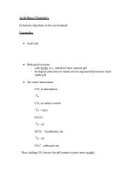
Load - Settlement GraphLoadSettlementUltimateBearingCapacity
Types of Load TestsRoutinegStaticgDynamicOther Methods (Discussed in DrilledShaft Section)gOsterberg CellgStatnamic
Static Load Test TypesASTM D1143gMaintained LoadgQuick Load (Texas Quick Test)gConstant Rate of Penetration (CRP)
Static Load Test - Test SetupReactionBeamLoad CellHydraulic JackRamStiffenersPlateSpherical BearingBourdon GageLVDTDial GageWireMirrorScaleTestPileGradeBracket Attached to Pile
Typical Arrangement for LoadTesting a Pile or Drilled ShaftReaction BeamDialGageJackSupportBeamTest Pile orDrilled ShaftAnchor Pile orDrilled Shaft
Static Load Test - MechanismQ 1 +Q 2 +Q 3 , etc.Q 1 +Q 2 +Q 3Q 1Q 1 +Q 2Load (Q)Telltale “A”MovementTelltale “B”Telltale “A”Pile HeadTelltale “B”
Reaction BeamStatic LoadTest LoadApplicationandMonitoringComponentsSpherical Bearing PlatesLoad CellHydraulic JackReference BeamReadout UnitJack Pressure GageJack Pump
Load Test Movement Monitoring ComponentsReferenceBeamDial GageLVDTSmoothSurfaceMagneticBase19-
Failure CriteriaThe commonly used failure criteria are based on theelastic pile compression plus an offset.The elastic compression, Δ, , is calculated asfollows:Δ = PL / AEWhere: P = axial load in kips (kN(kN)L = pile length in inches (mm)A = pile cross sectional area in in 2 (m 2 )E = elastic modulus of the pile material in ksf (kPa)
Failure criteria (b < 24 inches)The recommended offset is based on the pilediameter.In US Unitss f =Δ + (0.15 +b/120)where:s f = Settlement at failure load in inchesb = Pile diameter or width inchesΔ = Elastic deformation of total pile length in inches
Failure Criteria (b > 24 inches)The recommended offset is based on the pilediameter.s f = Δ + (b / 30)where:s f = Settlement at failure load in inchesb = Pile diameter or width in inchesΔ = Elastic deformation of total pile length in inches
QUESTIONgWould you feel comfortable using a pilethat has been tested to geotechnical(plunging) “Failure” in compression asa production pile?gWhy? / Why not?
LOAD TRANSFEREVALUATIONSg Determine relative resistance contributionsfrom shaft and toe.g Determine load transfer behavior along shaft(shaft resistance distribution).g Confirm, correlate, and calibrate staticanalyses, WEAP input, CAPWAP soilresistance distributions.g Refine dragload magnitudes.
VWSG sister barsfor concreteembedmentVWSG withwelded anchorblocks andprotectivechannel
Dynamic Pile TestingASTM D4945gMeasures strain and pile acceleration topredict capacitygRequires experienced personnel tointerpret resultsgCorrelates well with static test resultsgUsed for time-related capacity changes
Osterberg Load Test ConceptReaction SystemQ rR sR tQ oR sQ oExpandingOsterberg CellConventionalR tOsterberg
Osterberg Load Test SetupCell Expansion TelltaleDial Gage 2Friction CollarDial Gage 1High Strength PipeShaft Compression TelltalePile Top (Side Shear)Movement GageReference BeamHand OperatedHydraulic Pumpwith PressureGage andPressureTransducerPile ShaftResistancePrestressedConcrete PileOsterberg CellCast Into Pile
Osterberg Load Test MechanismDeflection Down Deflection UpMeasured ShaftFriction LoadCurve1 2 3Measured EndBearing Load Curve145ExtrapolatedFriction Curve2 3 4 5 667 891011879MaximumLoadfrom O-Cell TestLoad
Statnamic Load Test ConceptReactionMass-F SinPressureChamber+ F SinPile
Statnamic Load Test SetupConcrete or Steel Reaction MassPressure ChamberLoad CellBase Plate Grouted toFoundationLoose Granular FillPropellantLaunching CylinderPiston BaseDisplacementMeasuring MeansPile or Drilled Shaft
Statnamic Load Test Mechanism0-1Displacement (mm)-2-3-4-5-60 1 2 3 4 5Load (MN)
Examples of Cost SavingsFrom Pile Load TestinggWest Seattle Freeway - Major ProjectDesign Phase ProgramgNorth Carolina DOT - CoordinatedDesign Phase ProgramsgOregon DOT - Routine Project TestPrograms
West Seattle Freeway Bridge
West Seattle Freeway BridgeDesigngFriction Piles for all <strong>Foundations</strong>- 36” Diameter Open-end end Pipe Piles for MainChannel Piers (24,000 LF driven)- 24” Octagonal Prestressed Concrete Pilesfor Approach Piers (172,000 LF driven)
West Seattle Freeway BridgeItemEstimated RemarksSavingPiles $ 9,000,000 -Pile cap size $ 1,000,000 -Test pile dataprovided tobidders? Difficult toquantify savings
North Carolina Design PhaseLoad Test ProgramsProjects1994-19991999NeuseRiverProject Cost$ (Bid)Test Cost $(Bid)EstimatedSavings and (%)92,998,000 310,000 10,500,000 (11)New River 16,457,000 276,000 850,000 (5)ChowanRiverOregonInletCroatianSound33,923,000 375,000 1,357,000 (4)122,800,000 1,155,000 1,200,000 (1)88,963,000 998,000 1,800,000 (2)
North Carolina Design PhaseLoad Test ProgramsgBenefits to Project Design- Reduction in length- Increase in capacity- Reduced number of piles- Driveability, jetting, and set-up evaluated- Improved special provisions
North Carolina Design PhaseLoad Test ProgramsgBenefits to Project Construction- Improved special provisions- Restructured pay items- Eliminated unsatisfactory alternates- Established dynamic test criteria- Established pile equipment requirements- Reduced potential claims
North Carolina Design PhaseLoad Test ProgramsgBenefits of new technology verified….- Pile driving analyser- Osterberg cell axial test- Statnamic axial & lateral test- Integrity test procedures….and applied to reduce the costs ofsubsequent test programs
Cost Savings for Oregon DOT fromSmall Project Pile Load TestsBridgeLocationPile Size &TypeLengthReductionNetSavingsPilingSavingDennyRd.AllenBlvdAirportRd12” Sq.PrecastConcrete 30’12” Sq.PrecastConcrete 30’12¾” Closedend steelpipe 98’10’ $55,000 26%10’ $60,000 20%30’ $135,000 25%
Student Exercise 10gDetermine the failure laod for the staticload test plot shown below. Plot boththe elastic line and Davisson failure linefor a 14-inch square prestressedconcrete pile 35 ft in length and an f’ c of5,000 psi (Modulus of Elasticity of 4,000ksi)
Student Exercise 10
Student Exercise 10UsePLδ = to findAEδ @ P = 400 tons (800 kips)800,000196 inlbs × 35 ft × 12 in/ft.× 4,000,000 lbs/inδ ==2 2X = 0.15 in + 14/120 = 0.27 in0.43in
Student Exercise 10
Learning OutcomesgAt the end of this session, theparticipant will be able to:- Describe types of pile load tests and theirapplication- Define advantages of pile load testing
Any Questions?Any Questions?THE ROAD TOUNDERSTANDINGSOILSANDFOUNDATIONS
Interstate 0 – Apple FreewayNote: Scale shown in StationFormS.B.AppleFrwyN.B.AppleFrwyBaselineStationing90 91 92 93Interstate 0ProposedToe of SlopeExistingGround SurfaceProposed Final Grade21ProposedAbutment
AppleSubsurface ExplorationsTerrain ReconnaissanceSite InspectionSubsurface BoringsFreewayExerciseBasic Soil PropertiesLaboratory TestingVisual DescriptionClassification TestsSoil ProfilePo DiagramTest RequestConsolidation ResultsStrength ResultsgAppendix A- Section A.8SlopeStabilityApproach RoadwaySettlementDesign Soil ProfileCircular ArcAnalysis Sliding Block AnalysisLateral SqueezeDesign Soil ProfileSettlementTime – RateSurchargeVertical DrainsSpread Footing DesignConstructionMonitoringDesign Soil ProfilePier Bearing CapacityPier SettlementAbutment SettlementSurchargeVertical DrainsDriven PileDesignWave EquationHammer ApprovalEmbankment InstrumentationDesign Soil ProfileStatic Analysis – PierPipe PileH – PileStatic Analysis – abutmentPipe PileH – PileDriving ResistanceAbutment LateralMovement
Design Check of Driveability of12x84 H-pileH
Wave Equation Results Over 75-ft Depth for ICE 70S Hammer
Diesel Hammer Stroke vs BlowCount at 75-ft
Construction AspectsgPile Driveability- Driveability of 12x84 H-pile Hsection verifiedfor most difficult driving conditiongDriveability with Depth- Driveability of 12x84 H-pile Hsectioncomputed for whole 75-ft depth- Pile installation time expected to varybetween 16 and 20 minutes (no pre-augering)
Any Questions?Any Questions?THE ROAD TOUNDERSTANDINGSOILSANDFOUNDATIONS