

Installation Manual MPT33 - Electro Mechanical Systems Ltd.
Installation Manual MPT33 - Electro Mechanical Systems Ltd.
Installation Manual MPT33 - Electro Mechanical Systems Ltd.

Create successful ePaper yourself
Turn your PDF publications into a flip-book with our unique Google optimized e-Paper software.
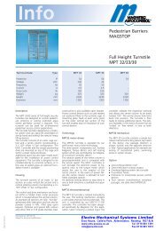
Operating InstructionsOperating Instructions Pedestrian Turnstile Type MPT 33Contents1. Delivery ........................................................ 2 2. Safety...........................................................2 3 Description and operation ............................3 4. Foundation ................................................4-5 5. Assembly and installation..........................6-9 6. Electrical connection .............................10-11 7. Access control devices............................... 12 8. Options....................................................... 13 9. Commissioning...........................................14 10. Technical support....................................... 14 11. Spare parts and accessories.................14-15 12. Warranty .................................................... 16 13. Controler MSC 10.................... ......... 20-22 581E,5811 10.03_MPT 33 1
Operating Instructions1. DeliveryThe Security Turnstile consists of:1 x Semi cage made of stainless steel or mild steel1 x Center column 3 x 120°, stainless steel or mild steel1 x Top housing with locking unit1 x U-bar locking unit1 x <strong>Electro</strong>nic controller MSC101 x Set of documents inside the lockable top cover1 x Fixing achors (in Europe only)2 x Keys for the top coverTechnical Data: Typ MPT 33Protection IP 54Voltage VACFrequencyCurrentHzA230502,5Duty CycleWeightHeightDiameter%Kgmmmm100320223013002. Safety2.1 General safety notesThe Magnetic pedestrian turnstile has been designed, built and testedaccording to the latest technology. Although it has left the factory in a fullyoperational and safe condition, it is important that the installation is carried outcorrectly therefore the operating instructions must be read carefully and thesafety notes must be observed.Any liability and warranty is declined by the manufacturer in the case ofincorrect use and use for purposes other than intended.2.2 Use for the intended purposeThe Magnetic pedestrian turnstile may be used only to control pedestrians entering or exiting restricted areas, usually under surveillance. The Magnetic Universal Controller may be used only for controlling theMagnetic pedestrian turnstile. Any other use is not permitted. Conversions and modifications to the turnstile or to the control modules are not permitted. Only original spare parts and accessories from Magnetic may be used.581E,5811 10.03_MPT 33 2
Operating Instructions2.3 Identification of risksPossible risks and notes are identified with the following symbols in theoperating instructions:Warning!This symbol in the operating instructions identifies actions and conditions which can give rise to danger for life and limb of persons. Observe the instructions carefully. Caution!All actions and conditions which can possibly give rise to damage to objects are identified with this symbol in the operating instructions. Observe the instructions carefully. Note!Relevant and useful notes for the user are identified with this symbol.2.4 Safety notes● Disconnect all external opening or closing devices (remote control, controldesk, etc.) during maintenance work● It is prohibited to install the barrier without proper mounting to thefoundation● A main power switch or residual current operated device is compulsory● Risk of bodily harm while cover is open● Pedestrian barriers are maintenance free● Documentation should be easily accessible.● Before commissioning make sure all electrical and functional features aretested.● Permissible environmental conditions● The electrical wiring of the barrier must comply with the included drawings.● Only certified and trained electrical technicians may perform the electricalconnections● Only certified and trained electrical technicians may remove covers formains plug,mains receivers or wirings● Before repairing electrical failures disconnect fuse● Risk of bodily harm if while closing the cover● During maintenance work the fixing bolt must be checked and tighten, ifnecessary.● Current carrying components like transformers, solenoids, resistors, statorhousings of motors, lamps etc. shall not be touched while in operatingtemperaturecondition; this can cause skin burns581E,5811 10.03_MPT 33 3
Operating Instructions3. Product descriptionThe MPT series of turnstiles are designed to control pedestrians entering orexiting restricted areas outside in high security situations. The turnstileconsists of four different component parts (see fig. 1) It can be used for bidirectionalaccess control by means of keys or card readers (access controldevices in general). Entry and exit of the barrier can either be operated inopen, controlled or closed modus. The rotating centre column consists of 3 x120 degreeU bars. The controller, the drive units and the locking device aremounted on top of the centre unit in a powder coated sheet metal enclosure,where there is also space for additional access control equipment .Lockingand release of the centre is realized by an electro-mechanical locking devicewith solenoids.Fig.1581E,5811 10.03_MPT 33 4
Operating Instructions4. FoundationA level concrete mounting surface is required to secure the turnstile housing. For the dimensions please refer to figure 2. The cables should finish a minimum of 5 meters above the finished concrete surface. NOTE: This foundation is also required in connection with a foundation frame. Conduits for mains supply and data linesshould finish 50 mm approx. above foundation Passage directionEmpty conduitEmpty conduitbearingPassage directionFig. 2Foundation anchor pinwith inside thread M10Drilling hole Ǿ 16Drilling depth 90 mm581E,5811 10.03_MPT 33 5
Operating InstructionsFoundation, smoothed finishto be positioned in waterin a level and horizontal mannerLay seperate conduits forpower supply and data cables,50 mm approx. above foundationAll power supply anddata lines are to be 5 m at leastabove the empty conduitConcrete PC 250with iron reinforcementAfter mountingglue set screw with LOCTITE 241or similarempty conduitO 25 mmsrewsplit washerwashersocketbearing neckwasherbearingFig.3581E,5811 10.03_MPT 33 6
Operating Instructions4.1 Foundation frameThe foundation frame is required for turnstiles to be mounted on a subground,for example in case of pavers. A level concrete mounting surface is requiredfor correct mounting of the foundation frame. It should be 150 mm approx.below the finished surface. Mounting of the foundation frame: correctpositioning of foundation frame, drilling of fixing holes, install fixing bolts, laythe foundation frame into water by means of jackscrews and tighten thefoundation frame.Fundamentdübel(F)Express-Anker M12x153/55 A4Bohrloch Ǿ12Bohrtiefe 145 mm incl. U-ProfilhöheFig.4Cable routing from foundationinto turnstileJackscrewsFor positioning the foundationFrame on the concrete, if necessary.581E,5811 10.03_MPT 33 7
Operating Instructions5. Assembly and installation5.1 To fit the turnstile (above ground foundation)• The turnstile should be positioned in its desired location taking care onwhich side (right or left) you want part 2 to place for access the system.This is important in case you want to mount housings for access controlunits at part 2.• Foundation drillings 7 x M16 as per drilling plan figure 2• Mount threaded rod (see enclosed separate description)• Wait till bolts are cured (see separate description)• Mount the components in correct order (part 1, 2..) onto the foundation,however, do not tighten entirely the bolts in order to compensate any drillingoffset which may occur afterwards. Use screws 6 x M 10 x35. Grease thescrews before.part 3part 1part 2part 4Fig.5• Place part 3 upon part 1 and 2. Use screws 8 x M12 x 35 and counternut.• Mount lower bearing (see fig. 8). Using screws M10 x 70. Grease thembefore.• Put part 4 on the lower bearing, see fig. 9 and screw it up by means of4 x M16 x 40 with U-discs and flange. Be sure that the turnstile is in lockedposition.• Now tighten all fixing bolts.581E,5811 10.03_MPT 33 8
Operating Instructions5.2 Fixing on foundation frameSee section 5.1 fixing the foundation. However in this case the turnstile is mounted on the flanges of the foundation frame. Fixing of foundation frame, see section 4.1 5.3 Opening of the top coverFig.6Opening by key. The cover is secured by means of a chain.Two keys are included in the delivery.581E,5811 10.03_MPT 33 9
Operating Instructions5.4 To fit the turnstile (above ground foundation)Fixing of the turnstile is done by means of the 8 fixing bolts M8 and plain washer. After final positioning tighten all bolts firmly.Note:1.Mark the dimensionsonto foundation acc. to fig.42. Drill3. Install turnstile4. screw together (see fig. 5.1Fig. 75.5 To fit the centre columnFig. 8581E,5811 10.03_MPT 33 10
Operating InstructionsFig. 9Mount the lower bearing on the foundation and stick the centre column on it.Fig. 10Fix the centre column by means of the delivered screws M16 at the top flange. Make sure the centre is in correct position (centre in locked position).581E,5811 10.03_MPT 33 11
Operating Instructions5.6 Assembly of roof with drainPlease see fig. 11.Fig.11581E,5811 10.03_MPT 33 12
Operating Instructions6. Electrical connectionsConnection of mains supply should only be performed b y a certified electrianand According to the connecting diagram or after discussion with the supplier.Fig. 12Fig.12Connection unit with control unit MSC10Fig.13581E,5811 10.03_MPT 33 13
Operating Instructions6.1 Connecting diagram MSC - 10counter passage passage alarmleftrightX17 X18 X19 X20 X21 X22 X23 X24 X25 X26 X27 X28 X29 X30not occupiedK1K K2K K3K K4KK5K24V / 400mA+10%/ -20%17 18 19 20 21 22 23 24 25 26 27 28 29 30 31 32MSCAlarmRS232 ON OFF1 2 3 4 5 6 7 8 910111213141516n.c.19VACor24VDCPE24V 24VSol.leftSol.rightIN1 = opening leftIN2 = opening rightIN3 = emergency releaseIN4 = reserveIN5 = limit switch leftIN6 = limit switch rightIN7 = reserveFIG.14581E,5811 10.03_MPT 33 14
Operating Instructions7. Housings / access control unitsFig.15Possible adaption of surface control devicesRear side of the mountingLead the cablefrom the rear sideof the mounting plateto the steel tubeand drill the hole.Here, for exampleFig.16581E,5811 10.03_MPT 33 15
Operating Instructions8. OptionPower fail locking mechanismThis mechanism will lock the centre column in one or both directions in theevent of a power failure. This requires changing of the solenoid, see fig. 17,the componentsare available on request ( additional kit for MPT 33, ref. no. 1031,5303).The centre column can be turned freely in both directions in its standardconfiguration.Fig.17581E,5811 10.03_MPT 33 16
Operating Instructions9. CommissioningOnce the mechanical and electrical installation of the turnstile has been completed, it can be put into service. Check before startup that all assembly and installation instructions have been followed and the electrical connections have been performed correctly. Warning:Incoming mains supply andconnections should only beperformed by a certifiedelectrician.Operation of the TurnstileThe Turnstile is generally operated by an access control system or control switches. Special control panels are also available for operation. 10. Technical SupportShould faults occur that cannot be rectified by a technician, please contact ourauthorised aftersales service representative.In special cases our Technical Support is available to you: Telephone:Please refer to the name plate on the turnstile housing for the data required inthe case of queries. This is found under the mechansim cover.11. Spare parts and accessoriesSee Figure 14 for the exploded drawing which details the individual parts andtheir identification numbers.581E,5811 10.03_MPT 33 17
Operating Instructions12. WarrantyThe manufacturer reserves the right to adapt technological progress withoutspecial announcement. Magnetic will be pleased to provide up to dateinformation and possible changes or additions to the operating instructions.Under the precondition that the operating conditions are complied with and noinadmissible interventions have been made to the interior of the equipmentand the equipment has no mechanical damage, a warranty of 2 year afterdelivery of the equipment applies on all mechanical and electricalcomponents.581E,5811 10.03_MPT 33 19
Operating Instructions13. Control Unit MSC 10Functions13.1 Functions of digital inputsInput 1 terminals X21 / X22 = Opening of passage direction leftOpening pulse passage left (entry).Input 2 terminals X24 / X 25 = Opening of passage direction rightOpening pulse passage right (exit)Input 3 IN3, terminal 11 = input emergency situationIn case of emergency passage free in both directions.13.2 Function of semi conductor outputsOutput 1 terminal X6 = solenoid leftOutput 2 terminal X7 = solenoid rightOutput 3 terminal X8 = reserve13.3 Function of relay outputsRelay 1 = counter pulse left terminal X18If the end position in passage direction left is reached a counter pulse of 300ms is given. This applies to permanent release also.Relay 2 = counter pulse right terminal X19If the end position in passage direction left is reached a counter pulse of 300ms is given. This applies to permanent release also.Relay 3 = Display passage free left terminals X22 + X21In case of free passage left a permanent signal is given. This output can alsobe usedto lock a pulse transmitter for passage right if passage left is given free.Relay 4 = Display passage free right terminals X 24 + 25In case of free passage right a permanent signal is given. This output can alsobe usedto lock a pulse transmitter for passage left if passage right is given free.Relay 5 = Error-/Alarm output terminal X27In case of certain errors a permanent signal is given as long as the error is noteliminated.Relay 6 = Reserve13.4 Safety functionsIn case of an error in the microcontroller the watchdog function releases ahardware reset.581E,5811 10.03_MPT 33 20
Operating Instructions14. Adjustable parametersThe following parameters can be adjusted by means of DIP switches andthe trimming potentiometer:DIP Function OFF ON1 Barrier type MPT MPP2 Pulse storage Off On = 4 pulses perdirection3 Locking delay time Off On = 1 sec.approx.4 Hardware tests *) *)5 Hardware tests *) *)6 Solenoid left Normal inverted7 Solenoid right Normal inverted8 Opening duration via LEDs No display displayDIP 1 Selection of barrier typeOne of the following barrier types must be selected:- MPP- MPTAt present this demand is locked; in every case barrier type MPT is selected.DIP 2 Pulse storageIn case the function is switched-off the demand pulses from one direction onlycan be processed. Demand pulses from the other side are then ignored.In case the function is switched-on max. 4 demand pulses per passagedirection can be stored.DIP 3 Locking delay timeIn order to avoid a rotation of more than 120° in case of permanent release orseveral stored pulses a locking delay time can be activated via a dip switch.The turnstile is then locked for 1 sec. approx after rotation of 120° and willthen be released for passing.DIP 6 SolenoidsVia DIP 6 and DIP 7 the function of both solenoids can be inverted separatelyfor both directions. This depends on whether the solenoids are integratedcurrentless open or closed. DIP 6 affect the left solenoid output and DIP 7the right one.581E,5811 10.03_MPT 33 21
Operating InstructionsDIP 5 Opening durationTo be adjusted via trimming potentiomenter between 1 – 32 sec..15. Operating modes15.1 Pulse operation in both directions without pulse storage15.2 Pulse operation in both directions with pulse storage15.3 Permanent release in both directions15.4 Pulse operation in one direction, permanent release in the otherdirectionRecommendationsRecommendation 89/392/EWG of 14.06.89 incl. modifications up to93/68/EWG of 22.07.03Recommendation 73/23/EWG of 19.02.73 incl. modifications up to93/68/EWG of 22.07.03Recommendation 89/336/EWG of 03.05.89 incl. modifications up to93/68/EWG of 22.07.03DIN VDE 0113 T1 06.93 (EN 60204-1-1992, IEC 204-1-1992)DIN EN 292 T2 11.91581E,5811 10.03_MPT 33 22


![[Linea System 2] - Electro Mechanical Systems Ltd.](https://img.yumpu.com/40569039/1/184x260/linea-system-2-electro-mechanical-systems-ltd.jpg?quality=85)


![[Linea D20 Fce]](https://img.yumpu.com/31507469/1/184x260/linea-d20-fce.jpg?quality=85)
![[Linea Micro XL]⢠⢠⢠- Electro Mechanical Systems Ltd.](https://img.yumpu.com/30934513/1/184x260/linea-micro-xla-a-a-electro-mechanical-systems-ltd.jpg?quality=85)