Griswold 811_Performance_Booklet_0707.pdf - Aquapump.co.za
Griswold 811_Performance_Booklet_0707.pdf - Aquapump.co.za
Griswold 811_Performance_Booklet_0707.pdf - Aquapump.co.za
- No tags were found...

You also want an ePaper? Increase the reach of your titles
YUMPU automatically turns print PDFs into web optimized ePapers that Google loves.
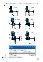
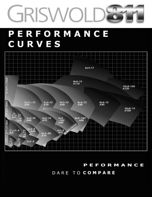
GRISWOLD PUMP COMPANYPUMP SIZE RPM PAGE #1 1/2 x 1 - 6AA 1800 13600 13 x 1 1/2 - 6AB 1800 13600 13 x 2 - 6AC 1800 13600 1LF 1 1/2 x 1 - 8AA 1800 23600 21 1/2 X 1 - 8AA 1800 23600 23 X 1 1/2 - 8AB 1800 23600 23 X 2 - 8 A60 1800 33600 34 X 3 - 8 A70 1200 31800 34 X 3 - 8G A70 1800 33600 3LF 2 X 1 -10 A05 1800 43600 42 X 1 - 10 A05 1800 43600 43 X 1 1/2 - 10 A50 1800 43600 43 X 2 - 10 A60 1200 51800 53600 54 X 3 - 10 A70 1200 51800 53600 54 X 3 - 10H A40 1200 61800 6PUMP SIZE RPM PAGE #6 X 4 - 10G A80 1200 61800 63600 66 X 4 - 10H A80 1200 61800 7LF 3 X 1 1/2 - 13 A20 1800 73600 73 X 1 1/2 - 13 A20 1200 71800 73600 73 X 2 - 13 A30 1200 81800 83600 84 X 3 - 13 A40 1200 81800 83600 86 X 4 - 13 A80 1200 91800 98 X 6 - 13 A90 1200 91800 910 X 8 - 13 A100 1200 91800 98 X 6 - 15 A110 1200 101800 1010 x 8 - 15 A120 900 101200 1010 x 8 - 15 G A120 1200 101800 106 x 4 - 17 A105 1200 116 x 4 - 17 A105 1800 11<strong>811</strong> Dimensional Data 128ll SpecificationsBack Coveri
GRISWOLD PUMP COMPANY1 1/2 x 1 - 6AA 1800 RPM Curve: G-18011 1/2 x 1 - 6AA 3600 RPM Curve: G-36013 x 1 1/2 - 6AB 1800 RPM Curve: G-1802 3 x 1 1/2 - 6AB 3600 RPM Curve: G-36023 x 2 - 6AC 1800 RPM Curve: G-1803 3 x 2 - 6AC 3600 RPM Curve: G-36031
GRISWOLD PUMP COMPANYLF1-1/2 x 1 - 8 AA 1800 RPM Curve: GLF-1804 LF1-1/2 x 1 - 8 AA 3600 RPM Curve: GLF-36041-1/2 x 1 - 8 AA 1800 RPM Curve: G-1804 1-1/2 x 1 - 8 AA 3600 RPM Curve: G-36043 x 1-1/2 - 8 AB 1800 RPM Curve: G-1805 3 x 1-1/2 - 8 AB 3600 RPM Curve: G-36052
GRISWOLD PUMP COMPANY3 x 2 - 8 A60 1800 RPM Curve: G-1807 3 x 2 - 8 A60 3600 RPM Curve: G-36074 x 3 - 8 A70 1200 RPM Curve: G-1208 4 x 3 - 8 A70 1800 RPM Curve: G-18084 x 3 - 8G A70 1800 RPM Curve: G-18094 x 3 - 8G A70 3600 RPM Curve: G-36093
GRISWOLD PUMP COMPANYLF2 x 1 - 10 A05 1800 RPM Curve: GLF-1810 LF2 x 1 - 10 A05 3600 RPM Curve: GLF-36102 x 1 - 10 A05 1800 RPM Curve: G-1810 2 x 1 - 10 A05 3600 RPM Curve: G-36103 x 1-1/2 - 10 A50 1800 RPM Curve: G-1<strong>811</strong> 3 x 1-1/2 - 10 A50 3600 RPM Curve: G-36114
GRISWOLD PUMP COMPANY3 x 2 - 10 A60 1200 RPM Curve: G-12123 x 2 - 10 A60 1800 RPM Curve: G-18123 x 2 - 10 A60 3600 RPM Curve: G-36124 x 3 - 10 A70 1200 RPM Curve: G-12134 x 3 - 10 A70 1800 RPM Curve: G-1813 4 x 3 - 10 A70 3600 RPM Curve: G-36135
GRISWOLD PUMP COMPANY4 x 3 - 10H A40 1200 RPM Curve: G-1214 4 x 3 - 10H A40 1800 RPM Curve: G-18146 x 4 - 10G A80 1200 RPM Curve: G-1215 6 x 4 - 10G A80 1800 RPM Curve: G-18156 x 4 - 10G A80 3600 RPM Curve: G-3615 6 x 4 - 10H A80 1200 RPM Curve: G-12166
GRISWOLD PUMP COMPANY6 x 4 - 10H A80 1800 RPM Curve: G-1816 LF 3 x 1-1/2 - 13 A20 1800 RPM Curve: GLF-1817LF 3 x 1-1/2 - 13 A20 3600 RPM Curve: GLF-3617 3 x 1-1/2 - 13 A20 1200 RPM Curve: G-12173 x 1-1/2 - 13 A20 1800 RPM Curve: G-1817 3 x 1-1/2 - 13 A20 3600 RPM Curve: G-36177
GRISWOLD PUMP COMPANY3 x 2 - 13 A30 1200 RPM Curve: G-12183 x 2 - 13 A30 1800 RPM Curve: G-18183 x 2 - 13 A30 3600 RPM Curve: G-3618 4 x 3 - 13 A40 1200 RPM Curve: G-12194 x 3 - 13 A40 1800 RPM Curve: G-1819 4 x 3 - 13 A40 3600 RPM Curve: G-36198
GRISWOLD PUMP COMPANY6 x 4 - 13 A80 1200 RPM Curve: G-12206 x 4 - 13 A80 1800 RPM Curve: G-18208 x 6 - 13 A90 1200 RPM Curve: G-12218 x 6 - 13 A90 1800 RPM Curve: G-182110 x 8 - 13 A100 1200 RPM Curve: G-1222 10 x 8 - 13 A100 1800 RPM Curve: G-18229
GRISWOLD PUMP COMPANY8 x 6 - 15 A110 1200 RPM Curve: G-1223 8 x 6 - 15 A110 1800 RPM Curve: G-182310 x 8 - 15 A120 900 RPM Curve: G-082410 x 8 - 15 A120 1200 RPM Curve: G-122410 x 8 - 15G A120 1200 RPM Curve: G-122510 x 8 - 15G A120 1800 RPM Curve: G-182510
6 x 4 - 17 A105 1200 RPM Curve: G-1227GRISWOLD PUMP COMPANY6 x 4 - 17 A105 1800 RPM Curve: G-182711
<strong>811</strong> DIMENSIONAL DATARO TAT IO NRO TA TIO N12
GRISWOLD PUMP COMPANYModel <strong>811</strong> ANSI B73.1 Specifications1.0 Pump Design1.1 The pump must <strong>co</strong>nform in all respects to the latest edition of ANSI Specification B73.1M.1.2 The pump should be back pullout design. A machined fit between the pullout assembly and the casing to insure alignment isrequired.1.3 Pump will be top centerline, self-venting discharge.1.4 100% of the pump shall be manufactured in the USA excluding outside purchased items like bearings and hardware that mayormay not be produced in the USA.2.0 Casing2.1 Class 150 pumps shall in<strong>co</strong>rporate class 300 wall thickness as standard, extending casing life under <strong>co</strong>rrosive / erosive<strong>co</strong>nditions.2.2 Casing shall be machined as to ac<strong>co</strong>mmodate a fully <strong>co</strong>nfined casing gasket to prevent leakage.2.3 The casing shall be furnished with a minimum 1/8" <strong>co</strong>rrosion allowance.2.4 The pump casing, when produced in Ductile Iron, Stainless Steel or CD4Mcu, shall include a drain plug and a dischargetap <strong>co</strong>nnection.3.0 Impeller3.1 A fully open impeller shall be provided to facilitate the handling of solid and stringy material.3.2 The impeller shall be self-tightening.3.3 The impeller shall be furnished with back pump out vanes to reduce pressure in the seal chamber and to minimize axial thrust.3.4 The pump shall be provided with an open impeller design to allow for re-establishment of original clearances and hydraulicperformance and efficiencies without pump disassembly.3.5 Impeller <strong>co</strong>nnection to the shaft shall allow for metal-to-metal <strong>co</strong>ntact with a <strong>co</strong>ntrol squeeze Teflon® o-ring.3.6 The impeller shall be balanced to minimize vibration in ac<strong>co</strong>rdance with ISO 1940 Grade 6.3 after final machining.3.7 The impeller shall be produced with ultra-smooth investment castings to improve hydraulic and mechanical balance.4.0 Bearing Frame and Adapter4.1 Non-pressure retaining castings (bearing housing, medium - large - extra large bearing frames, frame feet) shall be producedin cast iron with a minimum tensile strength of 30,000 lbs.4.2 Pressure retaining castings (small bearing frame, all adapters) shall be produced in Ductile Iron with a minimum tensilestrength of 65,000 lbs.4.3 Interior surfaces of all bearing frames shall be <strong>co</strong>ated with a Fusion Bonded Epoxy Coating to provide for long-term qualityand cleanliness of the lubricating oil.4.4 The bearing frames shall be assembled in a clean room environment to eliminate <strong>co</strong>ntamination.4.5 The bearing frame and adapter mating surfaces must be machined with a register fit to guarantee precise alignment.Additionally, dowel pins shall be utilized to eliminate torsion.4.6 The bearing housing with adjusting bolts shall be provided to allow for axial adjustment of the impeller to regain hydraulicperformance and efficiencies without pump disassembly.4.7 To minimize shaft misalignment due to flange loading on the pump, the frame foot, if separate from the bearing frame, shallbe rigidly attached at two points and <strong>co</strong>nstructed of cast iron with a minimum tensile strength of 30,000 lbs.4.8 The shaft shall be provided to keep deflection within ANSI B73.1 limits at all operating points.4.9 The shaft sleeve when provided will be hook type sleeve 316 stainless steel as a minimum or sleeveless solid shafts as anoption.4.10 Bearing shall be designed for a minimum life (L¹10) of two years and a 10-year average life as required by the latest editionof ANSI B73.1M specifications as manufactured by SKF or equal.4.11 Radial and thrust bearings shall not be pressed onto the shaft. Bearings shall be installed utilizing stress-free bearinginduction heater.4.12 To prevent thrust bearing loosening during pump operation, thrust bearings shall be positively locked to the shaft by means ofa locknut and lock washer.4.13 To retain lubricant and prevent <strong>co</strong>ntamination, bronze Inpro® labyrinth oil seals shall be provided.4.14 A one-inch sight glass with reflective baffle shall be provided to monitor oil level and <strong>co</strong>ndition.4.15 A magnetic drain plug shall be provided to <strong>co</strong>llect damaging metallic particles.4.16 Condition-monitoring sites shall be provided to facilitate <strong>co</strong>nsistent checking of vibration and temperature.4.17 If lubricant <strong>co</strong>oling is required a finned tube-<strong>co</strong>oling element shall be provided.4.18 In high load applications beyond ANSI <strong>811</strong>M bearing frame limits an <strong>811</strong>L frame shall be specified in<strong>co</strong>rporating an oversizedshaft with an oil slinger, higher load carrying radial bearing and duplex angular <strong>co</strong>ntact thrust bearings.5.0 Seal Chamber5.1 Seal chambers shall be engineered to provide the optimum seal environment for heat dissipation, solids, trapped air and vapor.6.0 Pump Bases6.1 A rigid, high-strength base shall be provided to insure pump-to-motor shaft misalignment not to exceed 0.005" due to baseplate distortion.7.0 Coupling Guard7.1 A <strong>co</strong>upling guard shall be provided with the pump that <strong>co</strong>nforms to both ANSI and OSHA requirements.8.0 Warranty8.1 Pumps shall be backed by a 3-year whole pump un<strong>co</strong>nditional guarantee against defects in material and workmanship.BC 7/07 C5312